

Page 1
Gardner
Bender
Instruction
Sheet
IMPORTANT RECEIVING INSTRUCTIONS: Visually inspect all components for shipping damage. If any shipping
damage is found, notify carrier at once. Shipping damage is NOT covered by warranty. The carrier is responsible for
all repair or replacement costs resulting from damage in shipment.
IMPORTANT USER SAFETY AND PROTECTION: In setting up systems to fit your operations, care must be taken
to select the proper components and design to insure appropriate integration with your operations and existing
equipment and that all safety measures have been taken to avoid the risk of personal injury and property damage
from your application or system.
GB ELECTRICAL CANNOT BE RESPONSIBLE FOR DAMAGE OR INJURY CAUSED BY UNSAFE USE,
MAINTENANCE OR APPLICATION OF ITS PRODUCTS. Please contact GB Electrical for guidance when you are
in doubt as to the proper safety precautions to be taken in designing and setting up your particular application.
Cyclone
Serial Numbers Begining With “E”
B2000
®
Bender
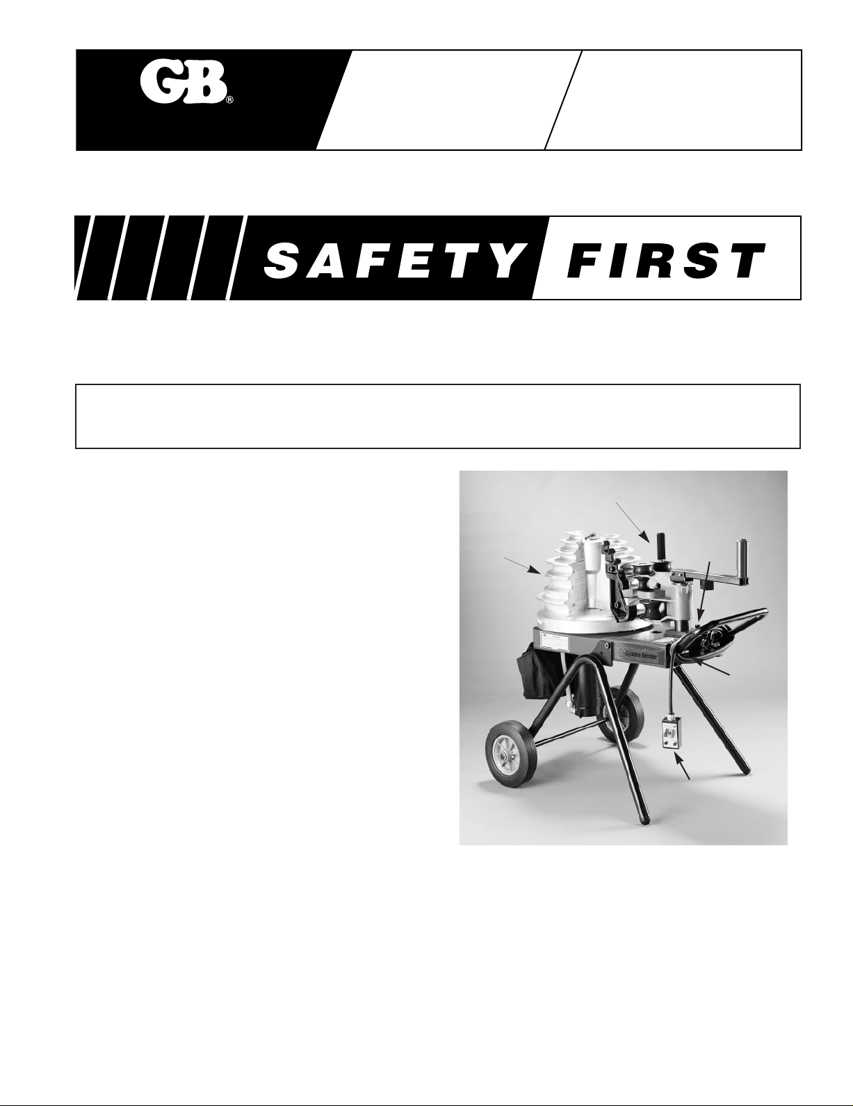
Description
The Cyclone®, GB model B2000 production bender is
used to bend EMT, IMC, rigid steel or rigid aluminum
conduit. A single bending shoe accommodates sizes
1
⁄2", 3⁄4", 1", 11⁄4", 11⁄2" and 2" conduit. The shoe is
driven by a 115 volt, 15 amp motor. The roller housing
consists of a single urethane roller and support arm,
also three sets of nylon rollers.
The bender control pendant consists of a zero light, an
override push button and a two-position toggle switch
for “Bend and Return”.
An 8-ft electrical cord connects the pendant to the
bender frame.
The bender can be used in a horizontal or
vertical position.
To avoid damaging the bender control circuit, an input
voltage sensing system is built into the control circuit. If
input voltage is less than 92V AC or higher than
132V AC the bender will shut off. One of the two lights
located on the end plate will light to indicate whether
high or low voltage exists.
Re-set the bender by unplugging the power cord, and
plugging it in again. If the incoming current voltage has
not been corrected, the bender will continue to shut off.
The voltage range must be within 92V AC to 132V AC.
Any situation which causes a voltage drop or increase
must be corrected before using the B2000 Bender.
Voltage drops may be caused by:
• Extension cords that are too long.
• Extension cords made of light (16-18 gauge) wire.
• Multiple power tools on a single circuit.
• Other devices which require high amperes to operate.
Bending
Shoe
Specifications
Power Source.............................120V 60 cycle AC
Pendant Control Circuit..............12V DC
Motor..........................................1 h.p. 100V 60 cycle
Weight........................................345 lbs.
Height.........................................38 inches
Width..........................................31 inches
Length ........................................45 inches
Fuses, Time Delay .....................15 Amp
Bend Capability..........................1⁄2" - 2" IMC, EMT
Upper Roller
Frame
Stop
High/Low
Voltage
Indicator
Pendant Control
Rigid Steel or Rigid
Aluminum
DC
Page 2
During pipe bending, stand behind the frame handle.
Keep hands, clothing and control cord away from the
bending shoe and rollers.
Select an operating area large enough to permit
loading pipe section and bending without striking
objects or personnel.
WARNING
!
Do not locate the bender on damp or wet surfaces. Do
not stand on wet surfaces while operating the bender.
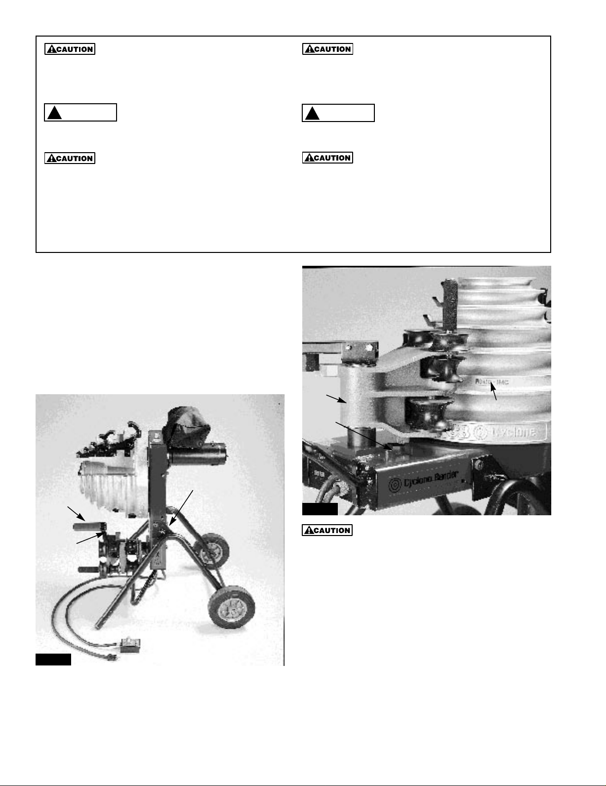
To prevent damage to the bending shoe, do not allow
the clamping jaws to strike the upper roller support arm
when the shoe is rotating. Position the roller housing
against the frame stop. See Figure 1.
WARNING
!
To avoid possible injury, do not place fingers under the
bottom edge of the bending shoe. See Figure 2.
Do not attempt to bend conduit or pipe other than 1⁄2"
through 2" IMC, EMT, rigid steel or aluminum. Bending
other materials will damage the bender and void the
warranty.
NOTE: All operations referring to “toward the operator” are viewed from the lifting handle end of the
bender frame.
Operation
Bending 1⁄2", 3⁄4" and 1" IMC, EMT and
rigid conduit.
1. Position the bender in a level dry area large enough
to permit loading and unloading various lengths of
conduit. Plug power cord into a 115 volt outlet.
Position the frame, either horizontally or vertically,
by pulling the spring loaded pin on the side of the
bender frame. See Figure 1.
Vertical Position
Roller
Housing
Material Idetifier
Frame
Stop
Positioning Pin
Upper Roller
Support Arm
Figure 1
2. Identify the type (IMC, EMT or Rigid) and size
conduit to be bent.
3. Locate the markings that indicate which grooves are
used for specific materials, and which grooves are
used for specific size conduit. See Figure 2.
Figure 2
To avoid damaging the rollers and roller housing, always
place the roller housing against the frame stop prior to
rotating the shoe.
4. Push the roller housing against the frame stop.
See Figure 2. Rotate the shoe to bring the required
grooves (EMT, IMC or Rigid) facing toward the
operator. To activate the shoe, hold the pendant
toggle switch in “Return” and press the override
button until the zero light goes out. The shoe will
rotate and stop in the load position. The zero light
will come on.
5. The upper urethane roller and support arm (figure 3)
is used for bending 1⁄2" through 1" conduit . One of
the top three shoe grooves will be used, depending
on conduit size.
2
Page 3

Jaw
Figure 3
Bend Groove
Frame Stop
6. When bending 1⁄2" - 1" conduit the upper roller and
support arm must be positioned between the shoe
and the roller housing. Position the urethane roller
by moving the roller housing against the frame stop
and removing the pin.
7. Lift the roller support arm to clear the nylon rollers
and swing the arm (toward shoe) over the roller
housing. Lower the arm into the support bracket and
insert the ring pin. See Figure 4.
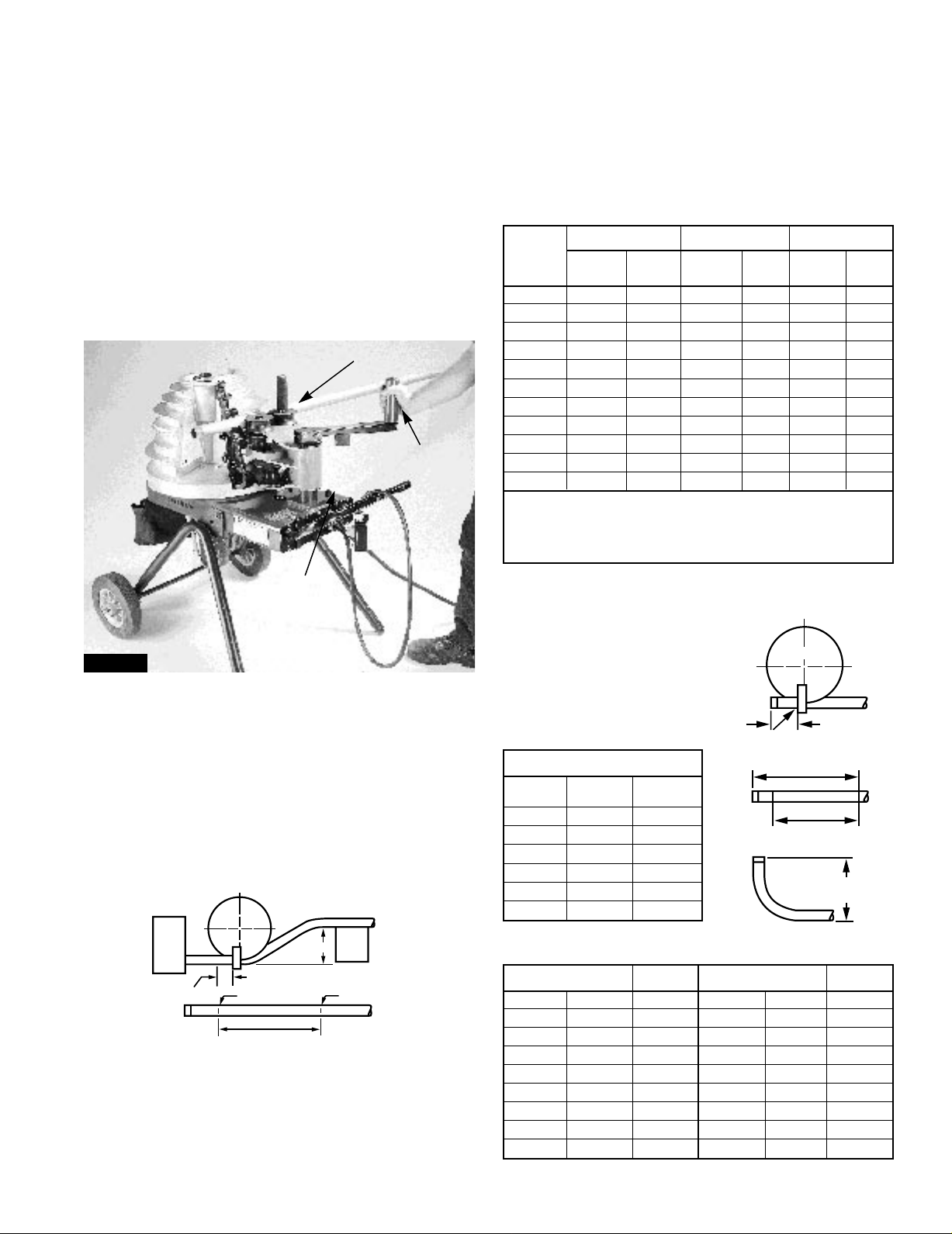
9. Each time a different size and type of conduit is
being bent, three facts must be determined and set
into the bender shoe control system. The required
settings are: conduit size, material and desired bend
angle. Prior to setting, be sure the desired size
indicator scale is toward the operator and the
correct shoe grooves are also toward the operator.
a. Lift the angle knob locking handle (figure 5).
Use the two small knobs to rotate the angle
disc, clockwise, until the red zero line is directly
in line with the zero line on the size scale.
b. Set the bender for specific conduit size by
turning the angle disc until the red line is on the
size indicator mark which matches the size
conduit being bent. Be sure the correct size
indicator is being used (EMT, lMC, or Rigid).
c. Move the bend angle knob (figure 5) until the
flat edge of the pointer is on a line indicating the
exact degree of bend desired. Lower the center
handle to lock the pointer and scale and to
prevent inadvertent movement during bending.
Locking Handle
Angle Set Knob
Rotating
Knob
Roller
Support Arm
Figure 4
8. Insert the conduit in the shoe groove marked with
the number matching the size conduit being bent.
The conduit must set in the shoe and in the jaw. The
end of the conduit must extend a minimum of 2"
beyond the jaw. See Figure 3. Refer to table A or B
on page 5 for bending data.
Angle
Indicator
Disk
Figure 5
Size Indicator
10. Activate the bending shoe by holding the pendant
control toggle switch in the “Bend” position. The
shoe will rotate until the angle set on the indicator
is reached.
11. To remove the conduit, hold the toggle switch in
“Return”. The shoe will return to the start position
and stop automatically. The zero set light will come
on. Bending more conduit of the same type and size
is accomplished by loading conduit and pressing the
toggle switch.
3
Page 4

Bending 11⁄4”, 11⁄2” and 2” Conduit
NOTE: All operations referring to “toward the operator”
are viewed from the lifting handle end of the bender
frame.
1. Bending 11⁄4" through 2" requires using one of the
three sets of nylon rollers and one of the grooves on
the lower half of the bending shoe.
2. Move the roller housing against the frame stop
(figure 10). The upper urethane roller must be on the
outside (toward frame handle) of the roller housing
(figure 6). If it’s not, pull the ring pin. Lift
the roller support arm, swing it over the roller
housing, lower the handle into the bracket and insert
the ring pin.
Nylon Rollers
Upper
Urethane Roller
Upper Urethane Roller
Nylon Rollers
Figure 6
Frame Handle
To avoid damage to the bending shoe, always place
the roller housing against the frame stop, prior to
activating the bending shoe.
3. Check the bending shoe to be sure the correct
grooves for the conduit being bent are facing toward
the operator. If the shoe must be rotated, hold the
pendant control toggle switch in “Return” and press
the override button until the zero light goes out. The
shoe will rotate 180° then stop in the load position
(figure 7).
4. When bending 11⁄4" - 2"
conduit, position roller
Zero Light
Override Button
housing and upper arm.
Then push the conduit
between the shoe groove
and the 2" nylon rollers
until the bend mark on the
conduit is in line with the
outside edge of the
clamp jaw.
5. Grasp the upper urethane
roller and move the support
Figure 7
Toggle
Switch
arm counterclockwise until
it contacts the roller housing. The two nylon rollers
should have moved against the conduit and should
firmly hold the conduit in the shoe (figure 8).
Figure 8
6. Each time a different size and type of conduit is
being bent, three facts must be determined and set
into the bender shoe control system. The required
settings are: conduit size, material and desired bend
angle. Prior to setting, be sure the desired size
indicator scale is toward the operator and the
correct shoe grooves are also toward the operator.
a. Lift the angle knob locking handle to release the
angle set knob and angle indicating disc. Use
the two small knobs to rotate the angle disc,
clockwise (figure 9).
b. Set the bender for specific conduit size by
turning the angle disc until the red line and
pointer are on an outer size indicator mark
which matches the size conduit being bent
(figure 9). Be sure the correct size indicator is
being used (EMT, lMC, or Rigid).
c. Move the bend angle knob (figure 9) until the
flat edge of the pointer is on the line indicating
the exact degree of bend desired. Lower the
center handle to lock the pointer and scale
and to prevent inadvertent movement
during bending.
Size Indicator
Set Knob
Zero Point
Figure 9
4
IMC/Rigid
Angle
Protractor
EMT Size
Indicator
Page 5
7. Use the control pendant. The zero light should be
Offset
Beam
Box
M
Front Edge of Clamp
See T able A
Min. 2"
Mark #2Mark #1
Shoe
Min. 2˝
Stub Length
Set Back
Mark #2
Mark #1
Front Edge of
Clamp Mark #2
Stub to Bottom
of Pipe
on. Hold the toggle switch in the “Bend” position.
The shoe will rotate until the desired bend is
achieved, then stop automatically.
NOTE: If the zero light is not on, press the toggle
switch to return until the shoe stops and the zero
light comes on.
8. To unload conduit, hold the toggle switch in the
“Return” position. The shoe will return to the start
position and stop automatically.
9. Grasp the upper urethane roller and move the
support arm clockwise until the rollers move away
from the conduit (figure 10). Push the roller housing
against the frame stop. Remove bent conduit.
Roller Housing Handle
Upper
Urethane Roller
3. Next rotate conduit 180˚ level, place mark #2 in
line with front edge of shoe clamp and make
second bend.
NOTE: When bending rigid aluminum, set bend
angle indicator approximately 4˚ short of
desired angle, since aluminum does not
have spring-back of steel.
Table A
15˚ Bend 30˚ Bend 45˚ Bend
Offset Conduit Conduit Conduit
Required Max. Size M Max. Size M Max. Size M
3
2”
4” 1
6” 2” 23
8” 30
10” 38
12” 46
14” 54
16” 61
18” 67
20” 77
22” 85” 44” 31
To locate distance between centers of offset bending marks other than listed in
table A use the following multipliers:
⁄4”7
1
⁄2”157⁄16”
3
⁄4”
3
⁄4”8”
3
⁄16” 1” 12”
5
⁄8”11⁄2” 16” 1” 115⁄16”
5
⁄8” 2” 20” 11⁄4”141⁄8”
3
⁄8” 24” 11⁄2”1615⁄16”
1
⁄16” 28” 2” 1913⁄16”
13
⁄16” 32” 225⁄8”
7
⁄16” 36” 257⁄16”
1
⁄4” 40” 281⁄4”
15˚ bend - 3.9
30˚ bend - 2.0
45˚ bend - 1.4
1
⁄2”81⁄2”
1
⁄8”
Frame Stop
Figure 10
10. To bend more conduit of the same material and at
the same angle, load and secure as described in
steps 3 through 6. To bend the same type conduit
but at a different angle, load and secure; turn angle
indicator to the desired angle, then press toggle
to bend.
11. Bending different type and size conduit requires
repeating steps 2 through 10.
Offset Bending
1. Obtain distance “M" from table A, and measure this
distance from mark #1 and place mark #2.
2. Now place mark #1 in line with front edge of shoe
clamp and make first bend.
Stub-up Bending
1. Table C shows
minimum length (inches).
2. Mark #1 is stub length,
deduct from this as per
table C and obtain mark #2.
Table B
BEND RADIUS
Conduit Radius Radius
Size Rigid / IMC EMT
1
⁄2”331⁄32”3
Table C
5
3
⁄4”4
1” 5
1
⁄4”6
1
1
⁄2”7
1
2” 8
1
⁄2” Rigid 73⁄4”1
1
⁄2” IMC 73⁄4”1
1
⁄2” EMT 75⁄8”1
3
⁄4” Rigid 9” 11⁄2” Rigid 131⁄2”
3
⁄4” IMC 9” 11⁄2” IMC 131⁄2”
3
⁄4” EMT 81⁄2”1
1” Rigid 10
1” IMC 10
1” EMT 10
25
⁄32”429⁄32”
9
⁄16”529⁄32”
7
⁄8”7
9
⁄16”7
9
⁄32”8
Conduit Stub-up Conduit Stub-up
Size Set-back Size Set-back
7
⁄8”
3
⁄32”
1
⁄2”
9
⁄16”
1
⁄4” Rigid 123⁄4”
1
⁄4” IMC 121⁄2”
1
⁄4” EMT 13”
1
⁄2” EMT 131⁄2”
1
⁄8” 2” Rigid 153⁄4”
1
⁄8” 2” IMC 151⁄2”
3
⁄8” 2” EMT 151⁄2”
Page 6

Maintenance
Gardner
Bender
A unit of Tools and Supplies
If motor will not run: Motor could become overheated
due to long repeated usage or severe strain. Allow
motor to cool. If motor still does not run check the fuse.
To avoid possible injury, always unplug the bender
power cord before attempting maintenance work.
Fuse Replacement: The fuse is located behind the
handle mounting plate. Remove the two brackets and
the mounting screws around the plate. Use caution to
avoid dropping the handle. Remove the handle
assembly and circuit control. Set the handle assembly
aside.
The fuse is located in a white bracket in the left corner
of the control panel (figure 11). Remove and replace
with a new 15 amp, 125 volt fuse, part number
E1601000. Connect the power cord and pendant
connectors, install the end plate. Check bender
operation.
For any repair other than above, contact an authorized
GB Technical Service Center.
Angle Adjustment
Two different size indicator scales are mounted on the
shoe outer rim. One for 1⁄2" thru 2" IMC and Rigid, the
other for EMT 1⁄2" thru 2" (figure 12).
Each size indicator is adjustable to compensate for over
long or short bends which may be due to differences in
conduit characteristics or other variations.
Bends which are too long: Loosen the indicator scale
(for type material being bent) mounting screws. Slide
the indicator clockwise as many degrees as the
overbend (if bend is 5˚ over, move indicator 5˚
clockwise). The degree of movement is observed by
watching one of the size marks as it moves past the
angle disc scale. Tighten the mounting screws.
Bends which are too short: Loosen the indicator (for
type material being bent) mounting screws. Slide the
indicator counterclockwise as many degrees as the
bend is short (if bend is 5˚ short move counterclockwise
5˚ ). The degree movement is observed by watching
one of the size marks as it moves past the angle disc
scale. Tighten the mounting screws.
Size Indicator Scale
Fuse
Figure 11
Handle Mounting Plate
Figure 12
Note: Two scales
one for rigid and
one for IMC
REPAIR AND SERVICE INSTRUCTIONS: For repair service and parts contact your nearest GB ELECTRICAL
Service Center. The GB ELECTRICAL Service Center will provide complete and prompt service on all GB
ELECTRICAL products.
PARTS AND SERVICE: For quality workmanship and
genuine GB ELECTRICAL parts, select an Authorized
GB Service Center for your repair needs. Only
repairs performed by an Authorized Service Center
displaying the official GB Authorized sign are backed
with full factory warranty. Contact GB Electrical
(414)352-4160 for the name of the nearest GB
Authorized Service Center.
WARRANTY: GB ELECTRICAL, INC. warrants its
product against defects in workmanship and materials
for 1 year from date of delivery to user. Chain is not
warranted. Warranty does not cover ordinary wear
and tear, abuse, misuse, overloading, altered products
or use of improper fluid.
WARRANTY RETURN PROCEDURE: When question
of warranty claim arises, send the unit to the nearest GB
Authorized Service Center for inspection, transportation
prepaid. Furnish evidence of purchase date. If the claim
comes under the terms of our warranty the Authorized
Service Center will REPAIR OR REPLACE PARTS
AFFECTED and return the unit prepaid.
6101 N. Baker Road • Milwaukee, WI 53209 • 414-352-4160 • Fax 414-352-2377
6
RPS-0097 1/98
 Loading...