

Gaylord C-6000-D Service Manual
THE
GAYLORD
EFFECTIVE DATE 05-10
TECHNICAL MANUAL
FOR THE C-6000-D CONTROL CABINET
GAYLORD INDUSTRIES
10900 S.W. AVERY STREET • TUALATIN, OREGON 97062 U.S.A.
800-547-9696 • 503-691-2010 • FAX: 503-692-6048 • email: info@gaylordusa.com
GAYLORD INDUSTRIES
World Headquarters: 10900 SW Avery Street • Tualatin, Oregon 97062 U.S.A.
To Our Customers. . .
Congratulations on your recent purchase of a Gaylord
kitchen exhaust hood system. We are proud to be able
to provide you with a quality product that incorporates
the latest engineering concepts and is a result of over 60
years of experience in the foodservice kitchen exhaust
industry.
If you have other Gaylord equipment such as a Gaylord
Ventilator, Utility Distribution System, Quencher Fire
Protection System, or Roof Top Air Handling Equipment,
etc., please refer to the corresponding supplementary
equipment manuals.
If you have further questions, please call us toll free at
1-800-547-9696 or email:info@gaylordusa.com. We are
more than happy to help.
Sincerely,
Gaylord Industries
PHONE: 503-691-2010 • 800-547-9696 • FAX: 503-692-6048 • email: info@gaylordusa.com • www.gaylordusa.com
COMMERCIAL KITCHEN EXHAUST SYSTEMS • FIRE PROTECTION • UTILITY DISTRIBUTION • ROOF TOP UNITS • POLLUTION CONTROL
STREET ADDRESS: 10900 S.W. Avery Street, Tualatin, Oregon 97062 U.S.A.
II

TABLE OF CONTENTS
GENERAL DESCRIPTION _________________________________________________________ 5
MODEL NUMBER DESCRIPTION ___________________________________________________ 6
STARTING THE C-6000-D COMMAND CENTER________________________________________ 7
MANUAL START _________________________________________________________________ 8
AUTOSTART ____________________________________________________________________ 9
REMOTE START ________________________________________________________________ 11
STOPPING THE EXHAUST/SUPPLY FAN(S) / STARTING WASH __________________________ 12
WASH MODES _________________________________________________________________ 13
EXTERNAL FIRE MODE __________________________________________________________ 17
INTERNAL FIRE MODE __________________________________________________________ 18
UV SAFETY ____________________________________________________________________ 20
UV COMPONENTS ______________________________________________________________ 21
UV SYSTEM ON ________________________________________________________________ 22
UV SAFETY INTERLOCKS ________________________________________________________ 23
UV LAMP FAILURE ______________________________________________________________ 24
FAN ON - UV SYSTEM OFF _______________________________________________________ 25
UV LAMP LIFE _________________________________________________________________ 26
PROGRAMMING INSTRUCTIONS (MENU) ___________________________________________ 27
PROGRAMMING INSTRUCTIONS (MENU) - CYCLE TYPE ______________________________ 28
PROGRAMMING INSTRUCTIONS (MENU) - DETERGENT ______________________________ 29
PROGRAMMING INSTRUCTIONS (MENU) - WASH LENGTH ____________________________ 30
PROGRAMMING INSTRUCTIONS (MENU) - DELAY TIME _______________________________ 31
PROGRAMMING INSTRUCTIONS (MENU) - SET CLOCK _______________________________ 32
PROGRAMMING INSTRUCTIONS (MENU) - AUTOMODE _______________________________ 33
PROGRAMMING INSTRUCTIONS (MENU) - SET WASH TIMES __________________________ 34
PROGRAMMING INSTRUCTIONS (MENU) - WASH TEST _______________________________ 35
PROGRAMMING INSTRUCTIONS (MENU) - # OF WASHES _____________________________ 36
GPC-6000 CABINET PARTS LIST __________________________________________________ 38
GPC-6000 PLUMBING PARTS LIST _________________________________________________ 39
C-6000-D PARTS LIST ___________________________________________________________ 40
C-6000-D PLC STATUS LIGHTS ____________________________________________________ 44
C-6000-D INTERNAL WIRING _____________________________________________________ 46
C-6000-D.1 INTERNAL WIRING ____________________________________________________ 48
C-6000-D EXTERNAL WIRING _____________________________________________________ 50
C-6000-D WASH CONTROL WIRING ________________________________________________ 52
C-6000-D TERMINAL VOLTAGES ___________________________________________________ 53
C-6000-D-UV PARTS LIST ________________________________________________________ 55
C-6000-D-UV PLC STATUS LIGHTS ________________________________________________ 60
C-6000-D-UV INTERNAL WIRING __________________________________________________ 62
C-6000-D-UV.1 INTERNAL WIRING _________________________________________________ 64
C-6000-D-UV EXTERNAL WIRING__________________________________________________ 66
C-6000-D-UV TERMINAL VOLTAGES ________________________________________________ 68
C-6000-D-UV WASH CONTROL WIRING_____________________________________________ 70
ALL RIGHTS RESERVED. NO PART OF THIS BOOK MAY BE REPRODUCED, STORED
IN A RETRIEVAL SYSTEM, OR TRANSMITTED IN ANY FORM BY AN ELECTRIC, MECHANICAL, PHOTOCOPYING, RECORDING MEANS OR OTHERWISE WITHOUT PRIOR
WRITTEN PERMISSION OF GAYLORD INDUSTRIES COPYRIGHT 2009.
© Copyright 2010, Gaylord Industries
The manufacturer reserves the right to modify the materials and
specications resulting from a continuing program of product
improvement or the availability of new materials.
ADDITIONAL COPIES $15.00
III

This page intentionally left blank.
IV
GENERAL DESCRIPTION
The C-6000-D Control Cabinet is designed to control one or more of the following Gaylord products;
• CG3 Ventilators
• CG3-UV Ventilators
• CG3-UV-SPC Ventilators
• RSPC-ESP Pollution Control Units
• Gaylord Duct Sumps (GDS)
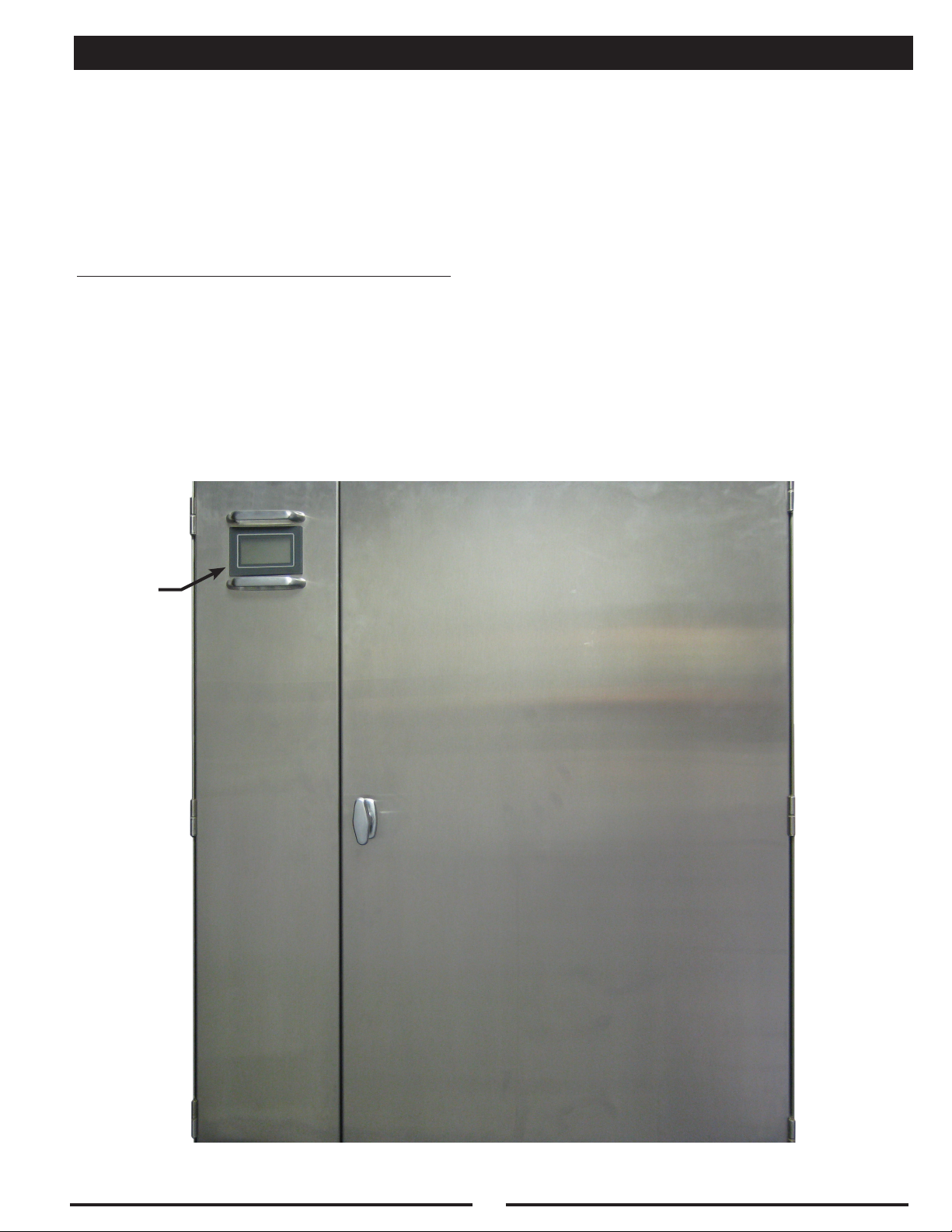
The C-6000-D Command Center will:
• Start/Stop Exhaust and Supply Fan(s)
• Control Wash system in Ventilators, Pollution Control Units, and/or Gaylord Duct Sumps
• Start/Stop Ultraviolet Lamps (UV)
• Start/Stop Electrostatic Cells (ESP or SPC)
• Interface with the Fire Protection (FP) system
• Interface with a Building Management System (BMS)
• Connect to an Autostart device, Gaylord model “TST”, if applicable
C-6000-D
COMMAND
CENTER
5
MODEL NUMBER DESCRIPTION
The C-6000-D Command Center is typically installed in a Gaylord Plumbing Cabinet (GPC). The model
number for the Gaylord Plumbing Cabinet is made up of an alphabetic prex followed by a series of
alphabetic and/or numeric sufxes to designate the type of control and various options. Sequence of
model numbers is as follows.
1._____ 2._____ 3._____ 4._____ 5._____ 6._____ 7._____ 8._____ 9._____ 10.____ 11.____
Prex Control # UV #
Sequences
Low
Detergent
Cold
Water
Mist
Light
Switch
Security
Access
Trim
Ring
Pipe
Size
220 Volts
Explanation of Pre-Fixes and Suffixes
1. GPC
GPC ...........................Gaylord Plumbing Cabinet
2. Control #
6000-D .......................Utilizes C-6000-D Control
3. UV (If Applicable)
UV ..............................Has inputs and outputs for Ultraviolet light control (UV)
4. # Sequences (# Wash Solenoids)
__ ...............................Leave BLANK for 1 plumbing sequence
S# ..............................Has # of plumbing sequences indicated to wash at different times
Ex) S2 – Has 2 plumbing sequences
S#/S# .........................On Main Cabinet that has a Sub Panel. The rst part (S#), indicates
the Total number of plumbing sequences controlled by the control.
The second part (S#), indicates the number of plumbing sequences
in the Main Cabinet. Ex) S5/S2: Controls a total of 5 plumbing sequences.
2 plumbing sequences in the main cabinet, and 3 plumbing sequences in
the Sub Panel.
5. Low Detergent
LD ..............................If cabinet has a Low Detergent Flow switch installed
6. Cold Water Mist
CM .............................If cabinet has a Cold Water Mist plumbing loop installed
7. Light Switch
LS ..............................If cabinet has a Light Switch installed
8. Trim Ring
TR ..............................If cabinet has a Trim Ring installed
9. Security Access
SA ..............................If cabinet has Security Access (Keyed Lift and Turn latch)
10. Plumbing Loop Size
1.00 ............................Indicates Plumbing Loop Size (diameter of pipe) in inches
11. 220 Volts
220V ..........................Indicates Control is designed to be connected to 220VAC Supply Voltage
Model Number Example:
GPC-6000-D-UV-S3-LD-CM-LS-TR-SA-1.25-220V
Sub Panel Model Number Example:
GPC-SUB-S3-LD-1.25
6
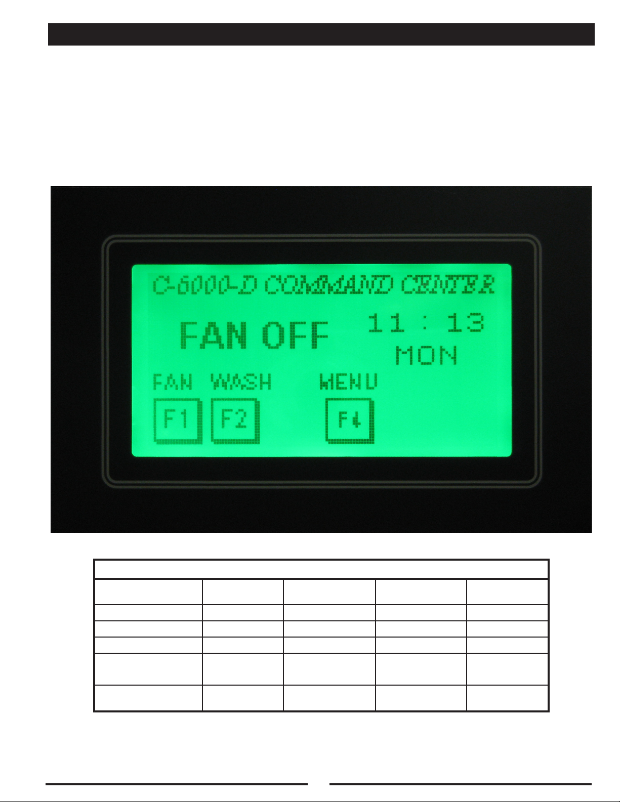
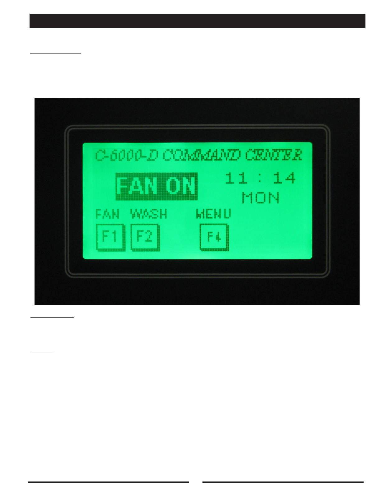
STARTING THE C-6000-D COMMAND CENTER
The C-6000-D can be started through one of three options:
1. Manually - - Press the “F1” (FAN) button
2. Autostart - - Autostart thermostats in the ventilator activate the C-6000-D
3. Remotely - - Remotely start the C-6000-D from a switch or BMS
* See the following pages for more details on each of these options
Typical Sequence of Operations for C-6000-D
Mode
Fan Off (Stand by) Closed Off Off Off
Fan On Open On On Off
Wash On Closed Off Off On
External Fire (Ansul)
Activated
Internal Fire
Thermostat Activated
Electric
Damper
Open On Off
Closed Off Off On
Exhaust Fan Supply Fan Wash
On
(After 60 Sec.)
7
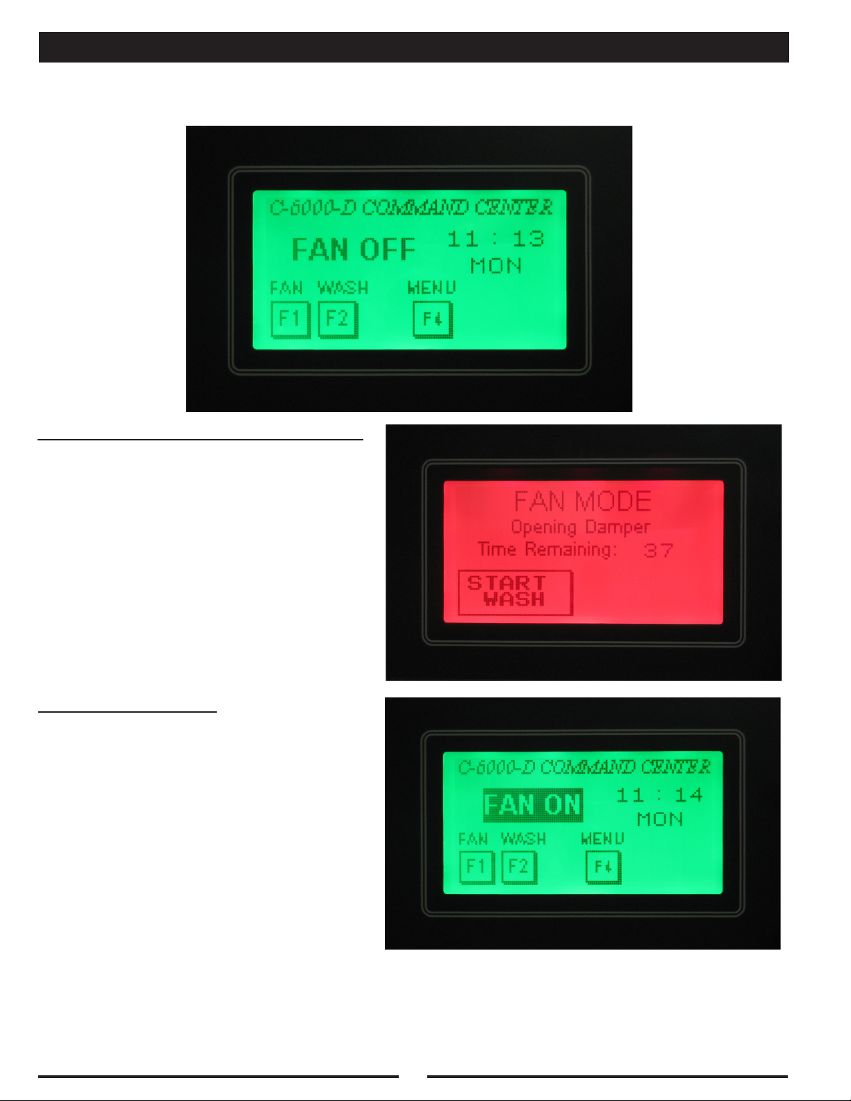
MANUAL START
To Start the Fan(s) press the “F1” (FAN) button.
Pressing the “F1” (FAN) button will result in:
1. Supply Fan On Starts immediately
2. The Electric Damper opens (after
approximately 45 seconds)
After a 45 second delay:
1. Exhaust Fan Starts
2. UV Lamps On (if applicable)
3. ESP or SPC Cells On (if applicable)
8
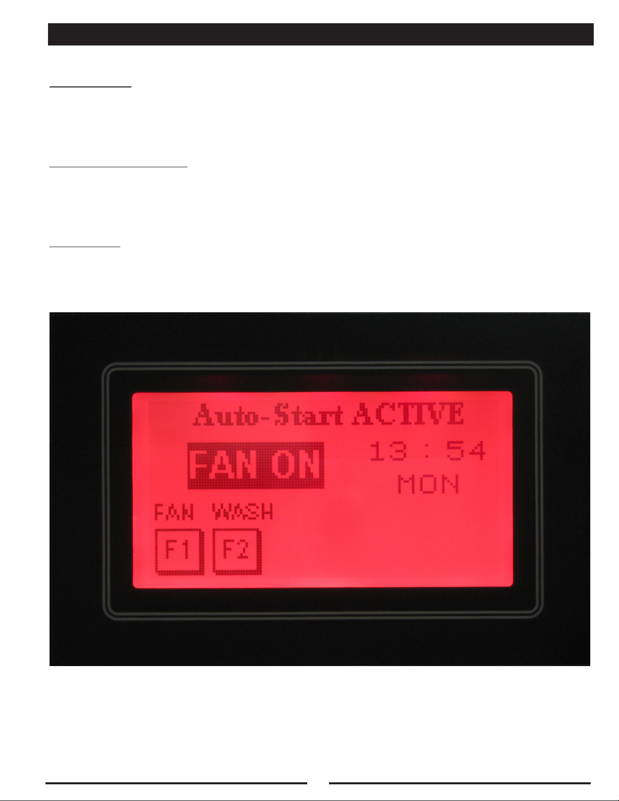
AUTOSTART
Description:
The C-6000-D is designed to start the Exhaust and Supply Fan(s) automatically when cooking starts,
if the ventilator it is connected to is equipped with Autostart thermostats, Gaylord model “TST”. The
Autostart thermostats (TST’s) are preset at the factory to 90°F, and may be adjusted in the eld, if
necessary.
Code Requirements:
Some municipalities require the exhaust fan to start automatically whenever cooking operations occur,
to comply with IMC 507.2.1.1. This code requires the exhaust fan to be interlocked with the cooking
equipment such that it will start whenever cooking operations occur. This can be accomplished with
Temperature Sensing Thermostat(s) in the ventilator, Gaylord model “TST”.
Operation:
Whenever the temperature in the ventilator canopy is above 90°F, and the C-6000-D is OFF, the Exhaust
and Supply Fan(s), UV Lamps (if applicable), ESP or SPC Cells (if applicable) will start automatically
in “Autostart” mode, and display the text shown below.
9
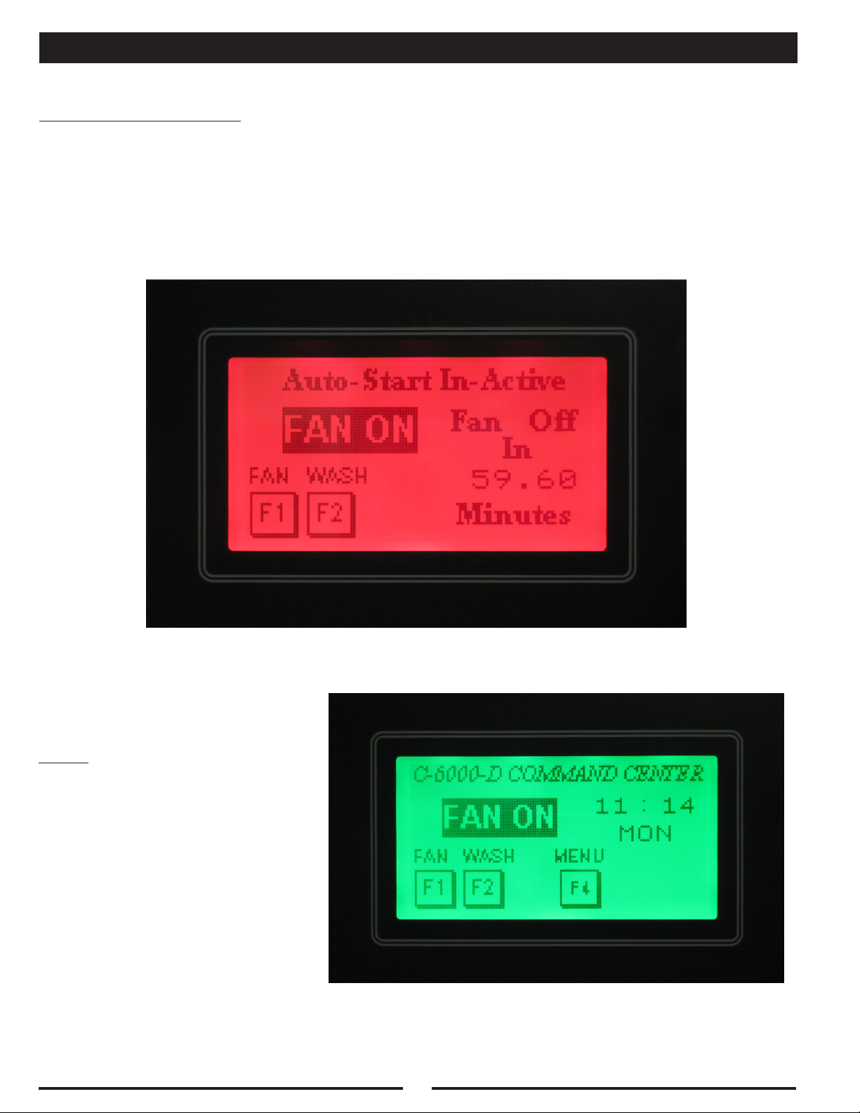
AUTOSTART
Automatic Shutdown:
After the temperature in the ventilator canopy drops below 90°F, the C-6000-D will start to countdown from
60 minutes. After 60 minutes the Exhaust and Supply Fan(s), and UV Lamps will shut off automatically.
Once the countdown has started:
1. The Fan(s), UV, and ESP or SPC cells can be started by pressing the “F1” (FAN) button and
cancel the countdown.
2. The Fan(s), UV, and ESP or SPC cells can be stopped by pressing the “F2” (WASH) button and
cancel the countdown, and Start the Wash.
Note:
The Fans and UV should be started
manually normally, by pressing the “F1”
(FAN) button. The Autostart is provided
as a back-up when the user forgets to
start the Fans before starting cooking.
While in “Autostart” mode, pressing
the “F1” (FAN ON) button will put the
C-6000-D back into a normal “FAN ON”
mode.
10
REMOTE START
Description:
The C-6000-D can be started remotely, from a Fan On/Off Switch located elsewhere, or from a Building
Management System (BMS). This is accomplished by connecting terminals “21” and “27” to a “Remote”
switch. Please note that terminal “21” has 24VDC on it. Refer to the C-6000-D Internal Wiring diagram
for more details.
Operation:
When the C-6000-D is Remotely Started, the Exhaust and Supply Fan(s), UV Lamps and ESP/SPC
Cells will start.
Note:
If the C-6000-D has been started “Remotely”, the Fan(s), UV, and ESP/SPC Cells cannot be shut off
at the C-6000-D. The C-6000-D must be shut off “Remotely” by removing power from terminal “27”.
When power is removed from terminal “27”, the C-6000-D will start to Wash.
11
STOPPING THE EXHAUST/SUPPLY FAN(S) / STARTING WASH
To Stop the Fan(s) and Start the Wash press the “F2” (WASH) button. The C-6000-D can also be set
to start the Wash Automatically. To do this set the C-6000-D to run in “AutoMode” and setting the times
to Wash in the Menu. See “Programming Instructions” for information on setting up the “AutoMode”.
CAUTION: The cooking equipment must be shut off prior to shutting off the exhaust fan. Failure to do
this will cause excessive heat buildup and could cause the surface fire protection system to discharge.
Pressing the “F2” (WASH) button will result in:
1. Exhaust Fan Off
2. Supply Fan Off
3. Electric Dampers Close (if applicable)
4. UV Lamps Off (if applicable)
5. ESP or SPC Cells Off (if applicable)
After a 45 second delay:
1. Wash Starts
12
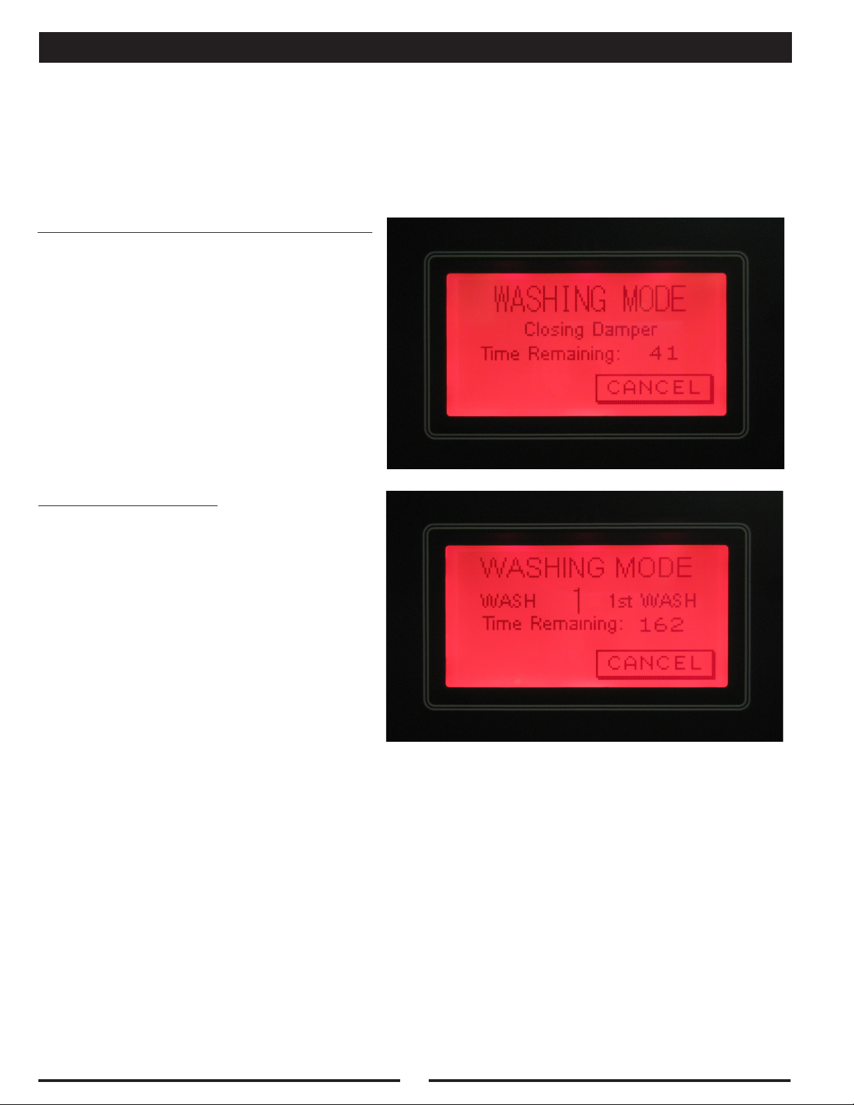
WASH MODES
The C-6000-D can be programmed to control up to 13
Wash Sequences (solenoids). The C-6000-D can control
“HOOD” wash cycles and “ESP” cycles, or a combination
of both. The length of each wash cycle can be set from 3 to
9 minutes. The delay between wash sequences can be set
from 1 to 99 minutes. The delay is designed to allow time for
the Hot Water to reheat if necessary and allow time for the
ESP or SPC cells to soak between wash cycles. To Start the
Wash, press the “F2” (WASH) button. The Fan(s) cannot
be restarted until the entire wash cycle has completed, or
the wash cycle has been canceled. To Stop the Wash before the wash cycle has completed, press the
“CANCEL” button. Refer to the “Programming Instructions” on how to adjust the times.
NOTE: The ventilator wash system is designed
to remove daily accumulations of grease within
the extraction chamber. If the ventilator is not
washed a minimum of once during a cooking
day, a grease buildup could accumulate which
the wash system cannot remove. If this occurs,
it is recommended that the ventilator be put
through several wash cycles by pushing the
“F2” (WASH) button on the Command Center.
If this does not remove the grease, it will be
necessary to remove the grease manually by
using a scraping tool, such as a putty knife,
or retain the services of a commercial hood
cleaning service to steam clean or pressure
wash the system.
Recommended Wash
Cycle Lengths
Type of Cooking
Light-Duty 3
Medium-Duty 5
Heavy-Duty 9
Length of
Wash Cycle
HOT WATER REQUIREMENTS
For proper operation of the wash system
there must be adequate water pressure and
temperature. There is a pressure/temperature
gauge inside the control cabinet.
Water Pressure: 40 psi min. - 80 psi max.
Water Temperature: 140°F min. - 180°F max.
13
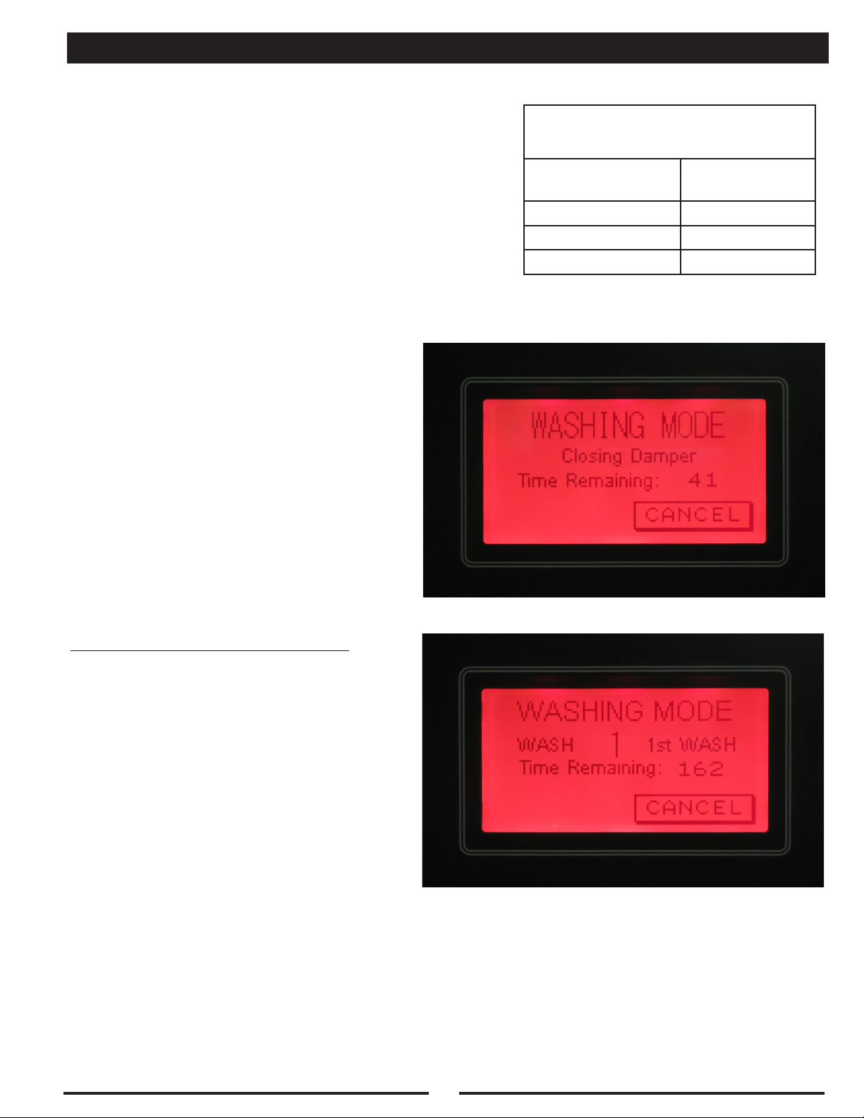
WASH MODES
“HOOD” Wash Description:
A “HOOD” Wash cycle is used for any water wash ventilator.
It will wash using Hot Water and detergent. If there is more
than one Sequence (solenoid), the C-6000-D will delay
between each Sequence, then the 2nd Wash Sequence
will start and run. After all of the washes are complete the
C-6000-D will display a “FAN OFF” message. Refer to the
table for a typical “HOOD” Wash.
WASH SEQUENCE #1
“HOOD” Wash Cycle (Typical)
Length of
Description
Wash #1 3
Delay 1
Wash #2 5
Total Time 9
DELAY
Wash Cycle
(Minutes)
WASH SEQUENCE #2
FAN OFF
14
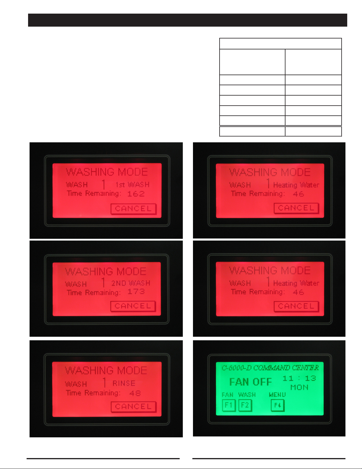
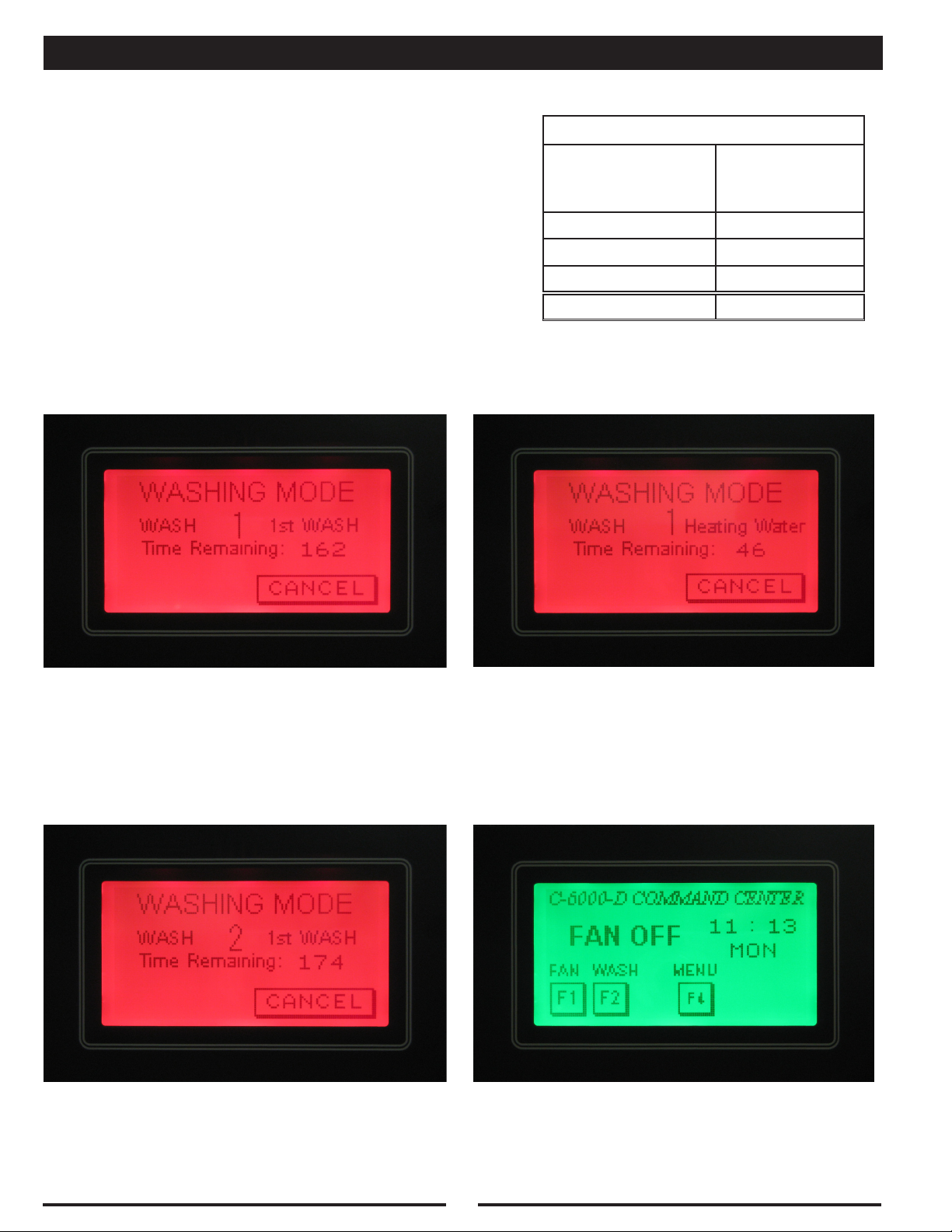
WASH MODES
“ESP” Wash Description:
An “ESP” Wash cycle is used for CG3-UV-SPC ventilators or
RSPC-ESP Pollution Control Units. An “ESP” Wash uses a
“Wash-Delay-Wash-Delay-Rinse” cycle. This is designed to
Wash the ESP or SPC cells with Hot Water and Detergent,
allow to soak, then Wash again, allow to soak, then Rinse
with Hot Water only. The length of the Wash cycles and the
Delay are adjustable. The length of the Rinse is xed at 3
minutes. After all of the washes are complete the C-6000-D
will display a “FAN OFF” message. Refer to the table for a
typical “ESP” Wash.
WASH #1
“ESP” Wash Cycle (Typical)
Length of
Description
Wash - 1st Wash 3
Delay 1
Wash - 2nd Wash 3
Delay 1
Rinse 3
Total Time 11
DELAY
Wash Cycle
(Minutes)
WASH #2
RINSE
DELAY
FAN OFF
15
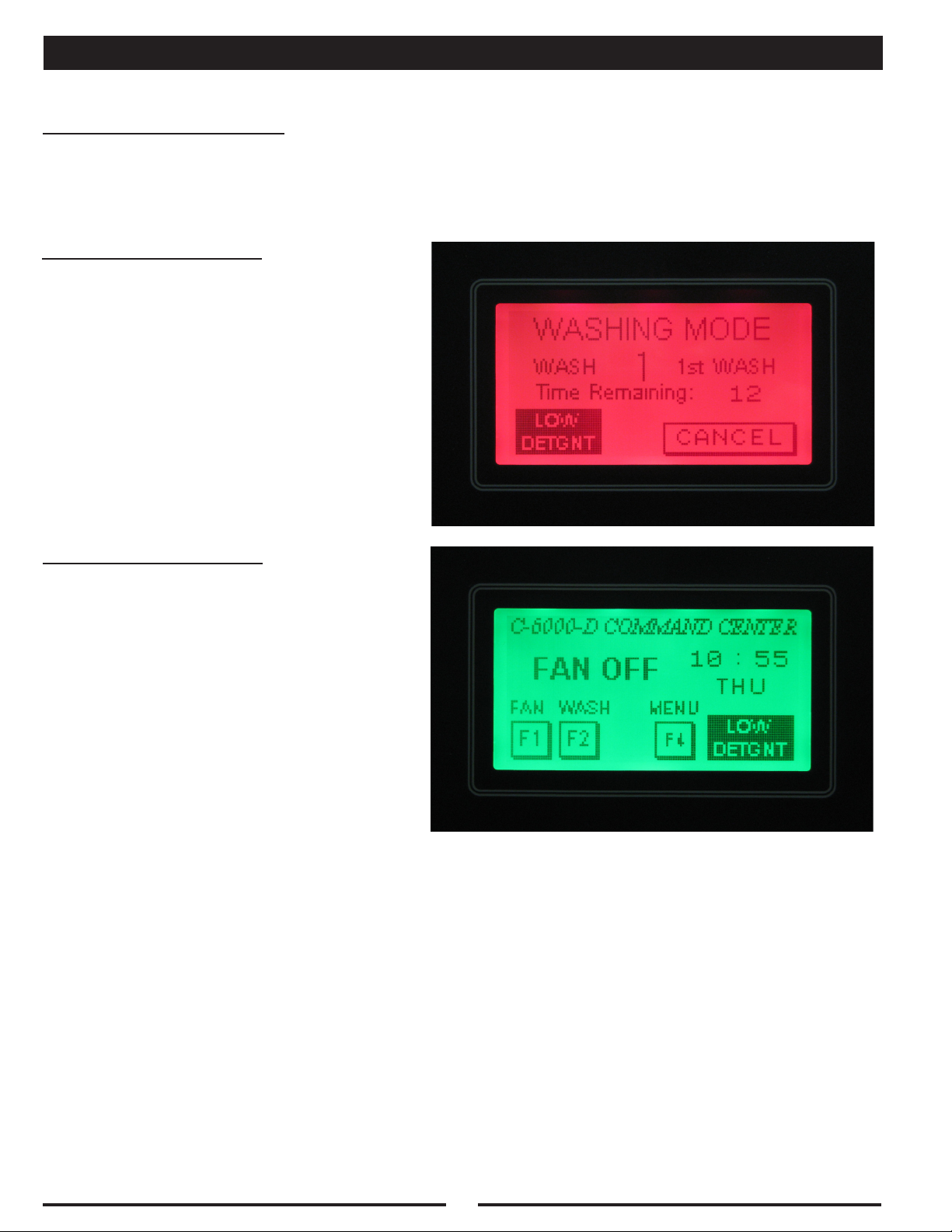
WASH MODES
Low Detergent (Option)
Some control cabinets are equipped with a low detergent ow switch. The control cabinet model number
would have the letters “LD” in the model number, if the it includes a low detergent ow switch
When the detergent is low:
A message will ash indicating “LOW DETGNT”
during the wash cycle. This indicates that the
detergent is low and/or the detergent pump is
not pumping
When the detergent is low:
A message will ash indicating “LOW DETGNT”
after the end of all of the wash cycles. This
indicates that the detergent is low and/or the
detergent pump is not pumping. To clear the
“LOW DETGNT” message, ll the detergent,
and run the C-6000-D through a Wash cycle.
It may be necessary to prime the pump, refer
to the “Detergent Pump Operation”.
Note:
If the detergent tank is lled with water or
detergents other than Formula G-510, the
detergent ow switch will act as if there is no
detergent. The viscosity of water and other
detergents is too low to be detected by the low
detergent ow switch
16
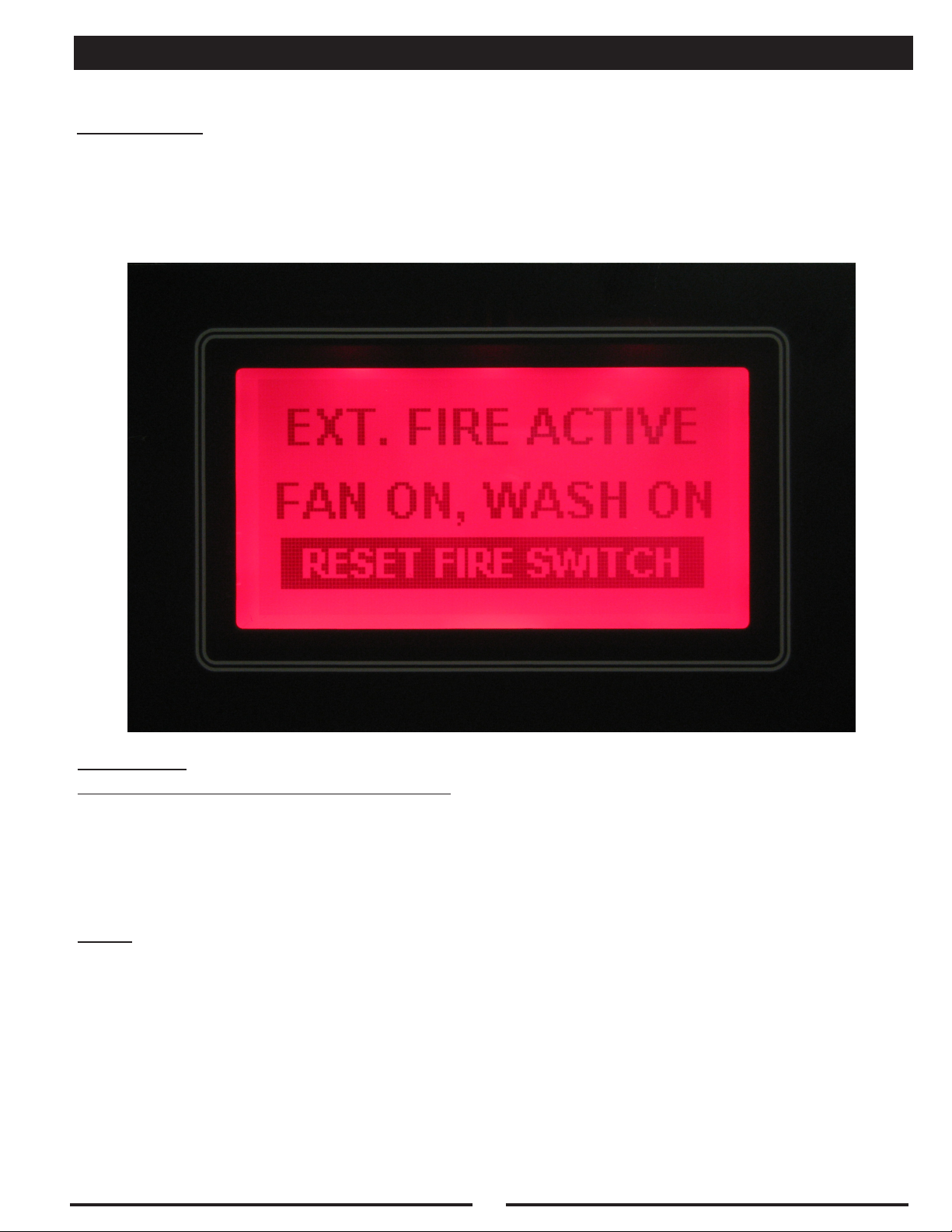
EXTERNAL FIRE MODE
Fire Protection System - Activated
Description:
The C-6000-D should be wired to the Fire Protection System for the Ventilator(s) and/or Pollution Control
Unit(s) it is controlling. A set of normally open contacts in the Fire Protection System needs to be wired
to terminals “4” and “FS” in the C-6000-D, refer to the C-6000-D Internal Wiring Diagram for more
details. Please note that terminal “4” has 120VAC on it. If the Surface Fire Protection System for the
Ventilator(s) is activated the C-6000-D will be placed in an “External Fire” mode.
Operation:
In an “External Fire” mode, the C-6000-D will:
1. Start Exhaust Fan
2. Shut off Supply Fan
3. Run water in ventilator(s) and/or Pollution Control Unit(s) after a 60-second delay
4. Close Alarm Contacts “A1” & “A2” - refer to C-6000-D Terminals for more details
5. Open Alarm Contacts “Q1” & “Q2” - refer to C-6000-D Terminals for more details
Note:
The Fan(s) cannot be restarted until the microswitch in the Fire Protection System for the Ventilator(s)
and/or Pollution Control Unit has been reset. After the microswitch has been reset, the Fan(s) can be
restarted by pressing the “F1” (FAN) button.
17
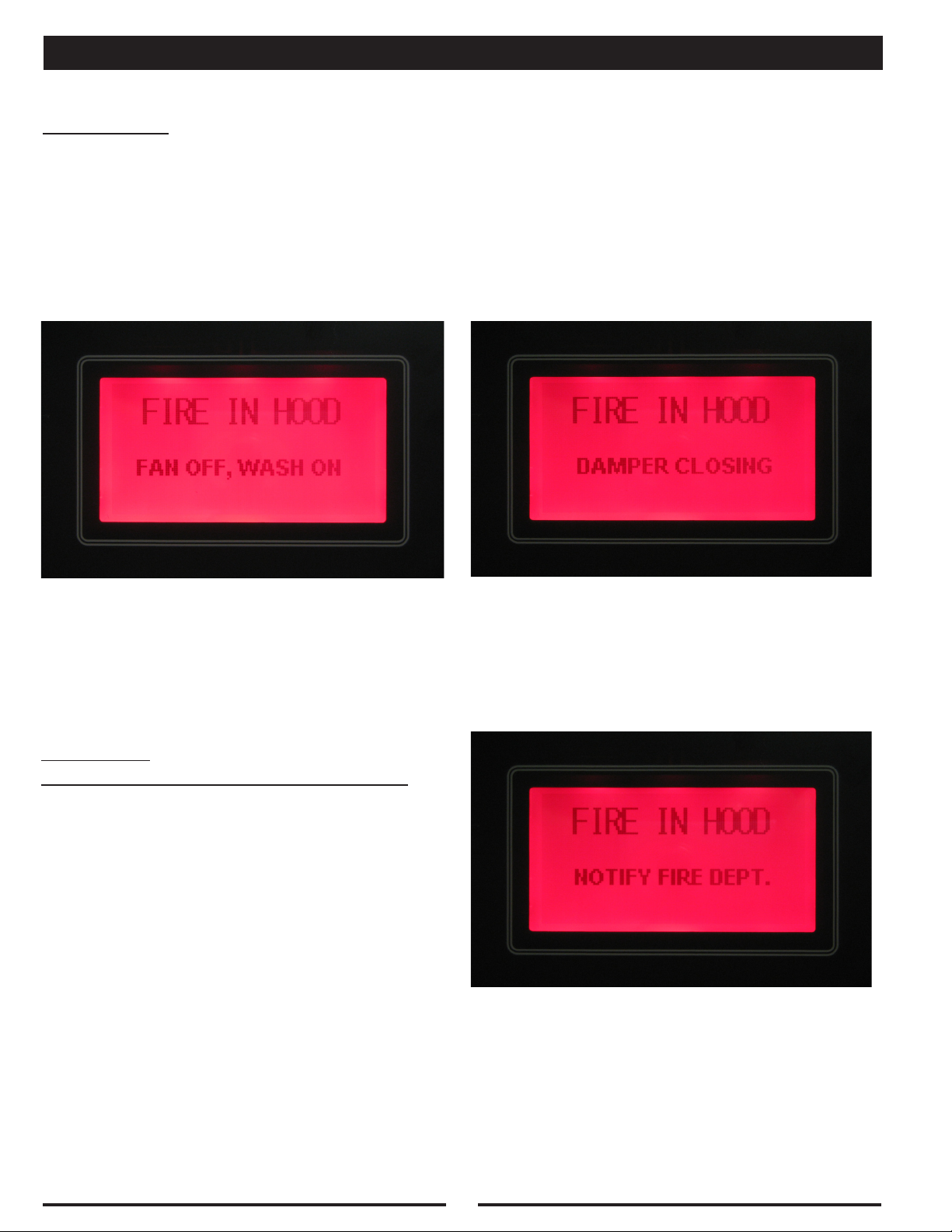
INTERNAL FIRE MODE
Thermostat - Activated
Description:
If the ventilator(s) connected to the C-6000-D are equipped with thermostat(s) at the duct/plenum to
detect re, and a re is detected at the Exhaust Duct collar, or if the thermostat in the Pollution Control
Unit detects a re, the C-6000-D will go into an “Internal Fire” mode. Refer to the appropriate Gaylord
Ventilator Technical Manual, or Gaylord Pollution Control Unit Technical Manual for thermostat location
and temperature setting.
1st Screen 2nd Screen
Operation:
In an “Internal Fire” mode, the C-6000-D will:
1. Shut off Exhaust Fan
2. Shut off Supply Fan
3. Run water in ventilator(s) and/or Pollution
Control Unit(s) immediately
4. Close Alarm Contacts “A1” & “A2” - refer to
C-6000-D Terminals for more details
5. Open Alarm Contacts “Q1” & “Q2” - refer to
C-6000-D Terminals for more details
3rd Screen
18
INTERNAL FIRE MODE
Thermostat - Activated
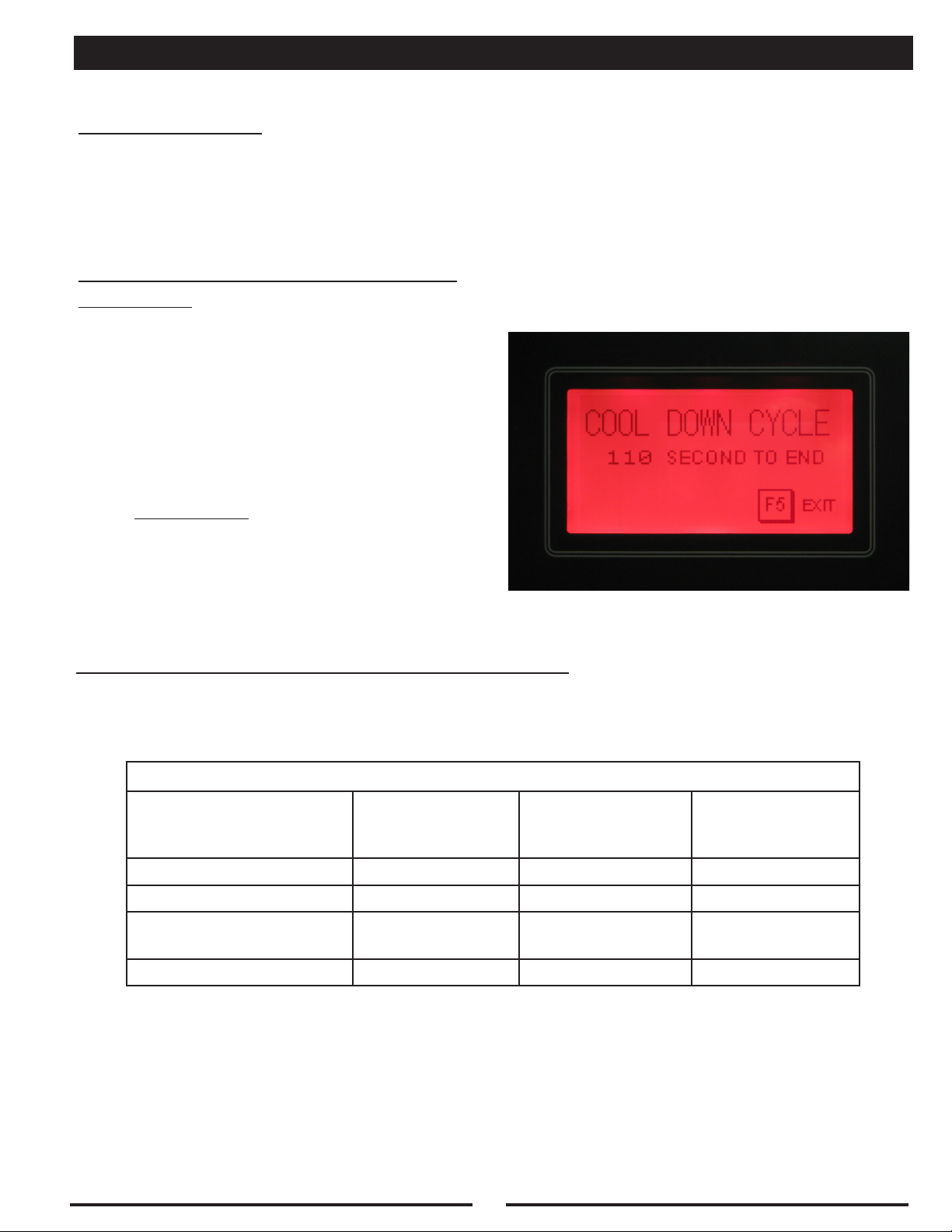
Cool Down Cycle:
After the temperature at the thermostat(s) cools below its’ activation temperature, the C-6000-D will
enter a “Cool Down Cycle” for 2 minutes. The C-6000-D will count down from 120 seconds. The water
will continue to run until the end of the “Cool Down Cycle”, or until the “F5” (EXIT) button is pressed.
After the “Cool Down Cycle is complete, the Fan(s) can be restarted by pressing the “F1” (FAN) button.
Internal & External fire modes at the
same time:
It is possible that both the Internal and External
Fire modes can be activated at the same time. If
this occurs, the Internal Fire Mode will override the
External Fire mode until the thermostat(s) cool below
the set point, refer to the appropriate Ventilator or
Pollution Control Technical Manual for the set point.
At this point the Cool Down Cycle will start counting
down for 2 minutes. After the Cool Down Cycle, the
External Fire mode will start.
Special Note: If the control is in the Cool
Down Cycle when the External Fire mode
is activated, the Cool Down Cycle will nish
counting down for 2 minutes, before switching
to the External Fire Mode.
Summary of Both Fire Modes at the Same Time:
1. Internal Fire Mode (until thermostat temperature drops below the set point)
2. Cool Down Cycle (for 2 minutes)
3. External Fire Mode (until the External Fire Switch is reset)
FIRE MODE SUMMARY
Cool Down Cycle
Exhaust Fan
Supply Fan
Electric Damper
Position (if applicable)
INTERNAL Fire
OFF OFF ON
OFF OFF OFF
FIRE EXHAUST EXHAUST
(for Internal Fire
Mode Only!)
EXTERNAL Fire
Water Spray
ON ON ON
19

UV SAFETY
Warning:
DO NOT defeat the purpose of the UV Safety Interlocks during Cleaning or Maintenance!
As with many types of technology if it is not used properly and/or proper precautions are not taken there
is the potential for injury or harm. This is especially true with UVC light due to the fact that it does not
physically hurt at the time of exposure. While UVC is very effective at breaking down grease molecules,
direct exposure to large amounts is harmful to skin and eyes. The amount of UVC generated in these
ventilators is greater than that what results from direct exposure to the sun. Under no circumstances is
it acceptable to view the lighted lamps without proper eye protection or expose bare skin directly to the
light. All interlocks and safety precautions called for in this manual must be followed to avoid the potential
for harm to service personnel and/or operators. In addition, only trained and authorized personnel may
perform some maintenance.
Personal Protective Equipment
Personal Protective equipment must be used at all times when working on any Gaylord “UV” ventilators,
this includes:
1. Eye protection that prevents 100% of UVC being transmitted through the lens must be worn at all
times when performing service work on any Gaylord “UV” ventilator that is energized and/or has the
potential to be energized and expose personnel to UVC light.
2. Whenever service work is performed it is recommended that long sleeve shirts and long pants be
worn to minimize the potential for inadvertent exposure of the skin to UVC.
20
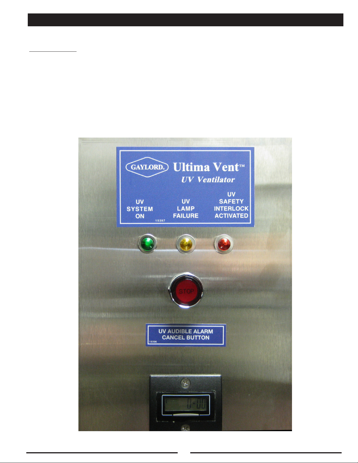
UV COMPONENTS
Description:
If the C-6000-D is controlling Gaylord “UV” ventilators, the model number will include “UV” in the model
number. The C-6000-D-UV will include the following components:
1. UV Status Lights
• Green - “UV System On”
• Yellow - “UV Lamp Failure”
• Red - “UV Safety Interlock Activated”
2. UV Audible Alarm Cancel button
3. UV Hour Meter
21
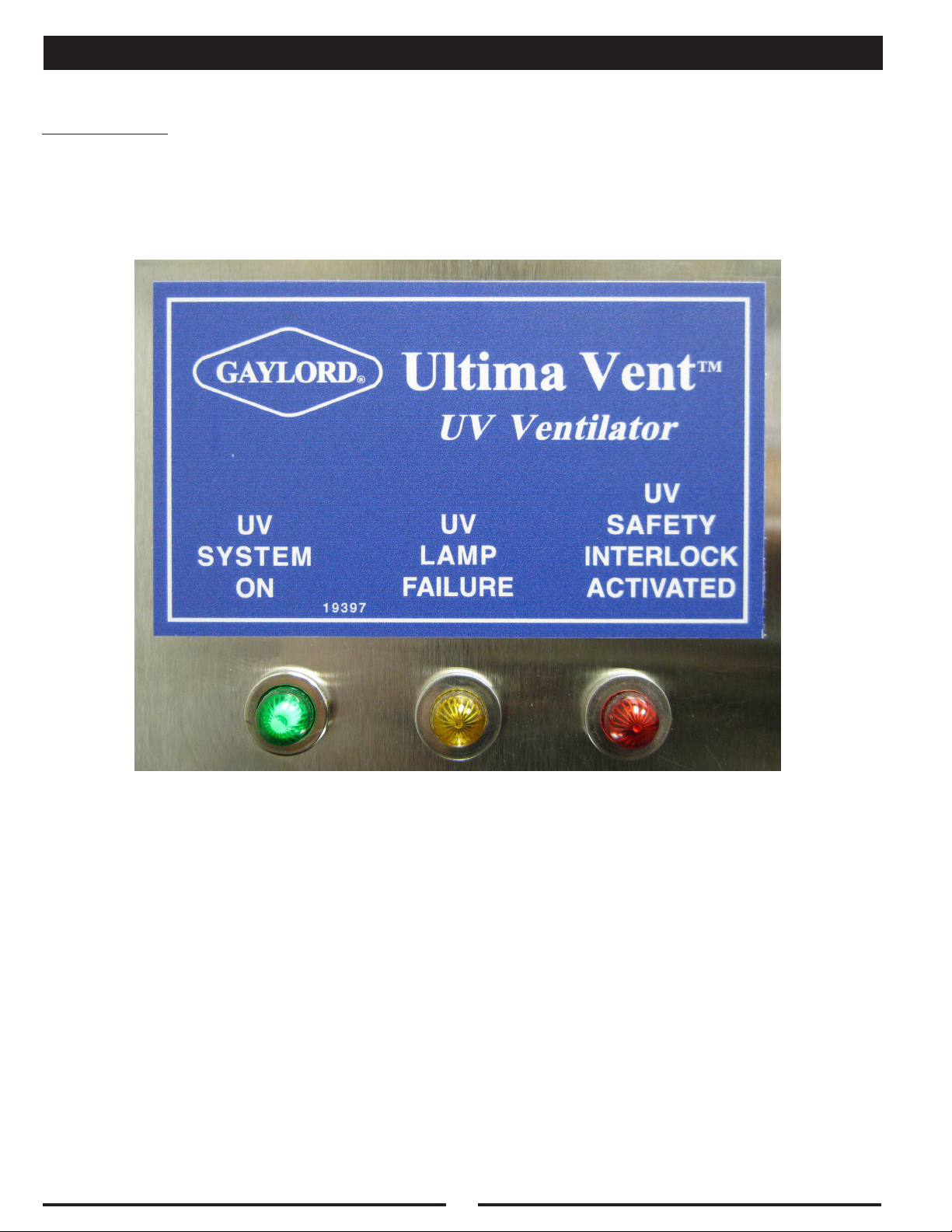
UV SYSTEM ON
Description:
When the C-6000-D-UV is running in the “Fan On”, “Autostart”, or “Remote Start” mode, the UV Lamps
will turn on. Under Normal conditions, when the UV Lamps are running normally the “UV System On”
Green light will illuminate. If either the Yellow or Red UV Lights are illuminated, refer to the following
pages.
22
 Loading...