

Page 1

Contents
About This Guide .................................................................................. iii
Checking Out Your Documentation..................................................... iii
Conventions Used in This Guide........................................................... iv
Chapter 1: Checking Out Your Notebook Computer .............. 5
Checking Out Your Solo 2500................................................................ 6
Keyboard and LCD panel ................................................................ 6
System Status Indicators (LCDs) .................................................... 8
Back ports panel ............................................................................. 10
Right side ports and bays ............................................................... 11
Left side ports and battery bay....................................................... 12
Bottom release latches and memory bay....................................... 13
Chapter 2: Getting S tarted ............................ ......... ......... ..... .1 5
Getting Your System Running.............................................................. 16
Installing the battery pack.............................................................. 16
Connecting the AC power.............................................................. 18
Starting up your notebook.............................................................. 19
Chapter 3: Using Your Notebook ..........................................2 3
Using Your Solo 2500........................................................................... 24
Using the keyboard......................................................................... 24
Using key combinations................................................................. 25
Using the LCD................................................................................ 29
Using the pointing device............................................................... 31
Using the audio............................................................................... 39
Using diskette media (3.5" or LS120 diskettes)............................ 41
Using disc media (CD-ROM)........................................................ 42
Removing and replacing the hard disk drive ................................ 44
Using PC Cards .............................................................................. 46
Using the IR port ............................................................................ 48
Using the USB ports....................................................................... 51
Using McAfee VirusScan .............................................................. 52
i
Page 2

Chapter 4: Managing Power Usage ......................................55
Maximizing Power Management......................................................... 56
Charging the battery pack.............................................................. 56
Using the battery............................................................................ 58
Monitoring the battery status......................................................... 59
Setting the power button................................................................ 60
Using the suspend and standby modes.......................................... 61
Maximizing the battery life ........................................................... 63
Appendix A: A ccessorie s ................................... ......... ..... ......65
Solo Notebook Accessories ................................................................. 66
Appendix B: Usin g the B IOS Se tup Progra m .......................69
About the BIOS Setup Utility............................................................... 70
Using the BIOS Setup Utility........................................................ 70
Appendix C: Contact ing Gate way ....................................... ..73
Contacting Gateway.............................................................................. 74
Calling Gateway ............................................................................ 74
Calling Gateway when outside the
U.S. and Canada............................................................................. 75
Index .......................................................................................77
ii Using Your Gateway Solo 2500 Multimedia Notebook
Page 3

About This Guide
This document provides an overview of your Solo 2500 and information
about using it.
Chapter 1: “Checking Out Your Notebook Computer” helps you get
familiar with the ports and components on your notebook.
Chapter 2: “Getting Started” provides information about setting up your
notebook.
Chapter 3: “Using Your Notebook” covers using the system ports and
connecting peripherals to your computer. It also discusses some common
uses for your computer.
Chapter 4: “Managing Power Usage” provides information about maximizing
battery power and using Standby, Suspend, and other system modes.
Chec king Out Your Documentation
In addition to this User Guide, we’ve also provided other documentation to
help you maximize using your system. Please refer to the following printed
and online documentation for additional resources:
♦ Printed manuals
•
The “Maintaining and Troubleshooting Your Solo 2500 Notebook”
contains information about managing system resources, preserving
your system performance, reinstalling your operating system and
drivers, and general troubleshooting tips.
•
Windows 95, 98, or NT manual (dependent upon the operating
system you ordered) provides information about using the
operating system, learning about advanced features, networking,
getting help, and more.
♦ Online documentation - Lets you access the electronic manuals from
your hard drive when you are traveling or when the manuals are not
accessible. To access the online documentation click
Documentation and select the manual you want to review.
Start, Online
iii
Page 4
♦ Gateway Website (http://www.gateway.com) - If you have a modem,
an analog phone line, and a subscription to an Internet service provider
you can tap into some of the latest help and other information on our
website. We provide tech support help, technical documents, tech tips,
FAQs (Frequently Asked Questions), glossary, software library with
BIOS updates, and other resources that can help you make the most of
using your notebook.
Con ventions Used in This Guide
This book uses the following conventions to help identify information:
Conventi on example Description
ENTER
C
TRL+ALT+DEL
c:\setup
Click OK
“User’s Guide”
Note:
This is an example of an
important note that may
appear in the manual.
Key names, which correspond to
keys on the keyboard, are printed in
small capitals.
Letters in small caps. A plus sign
between ke y s in dicate s that the k e y s
must be pressed simultaneously.
Commands to be typed are represented in all lower case characters
on an individual line.
Options to click or select are printed
in bold (actions to be taken by user).
Names of publications and cross-referenced headings are printed in quotations.
Sidebars give critica l information
such as warnings and important
notes.
iv Using Your Gateway Solo 2500 Multimedia Notebook
Page 5

Chapter 1:
Checking Out Your Notebook Computer
Checking Out Your Solo 2500................................ 6
Page 6
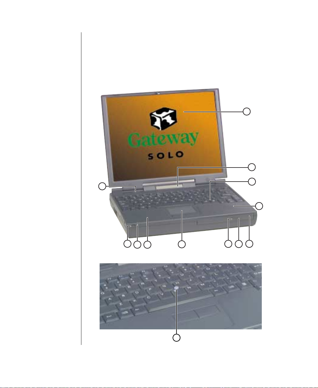
Checking Out Your Solo 2500
Take a tour of your notebook to familiarize yourself with its options.
K eyboard and LCD panel
A
B
K
J
I
H
G
G
F
C
H
D
E
6 Using Your Gateway Solo 2500 Multimedia Notebook
Page 7
Component Icon Description
A. Color Liquid Crys-
tal Display (LCD)
shown w/ 13.3” LCD
B. System status
Provides sharp, crisp resolution with backlit
anti-glare screen.
Indicates the system status modes.
indicators
(LCM - Liquid
Crystal Module)
C.Keyboard Provides full functionality of a desktop com-
puter keyboard. Many of these keys have
been assigned alternate functions, including
shortcut keys for Windows 95, Status Display
menus, and numeric keypad.
D. CD -ROM drive The
E. CD-ROM
emergency eject
hole
F. CD- R O M
eject button
G. Enhanced EZ
Provides manual eject capability to remove a
CD if power is unavailable. Insert a straight-
ened paper clip to eject the CD tray.
Ejects the CD-ROM tray from the drive. This
button is functional only when power is on.
Controls the cursor movement on the screen.
CD-ROM
reads data CDs or audio CDs.
Pad™ TouchPad
or EZ P oint™
H.Speakers Provides high quality sound reproduction for
software and audio CDs.
I. Power LED Indicates system power status:
•Steady green = power is On
• Blinking green = system is in suspend mode
or standby mode. The LED will flash every
four seconds.
• LED off = power is Off
J. Microphone Provides buil t-in omni -dir ectional audio
recording capability.
K. Power button Press to turn power ON or OFF. Can also be
configured to Suspend/Resume mode.
Chapter 1: Checking Out Your Notebook Computer 7
Page 8
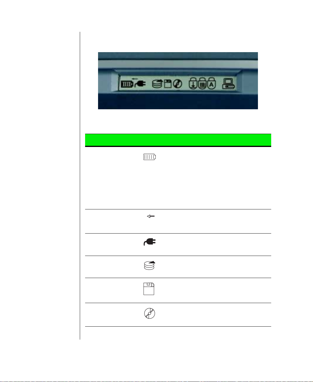
System Status Indicators (LCDs)
Indicator Icon Description
A. Battery gauge Appears when a battery is installed. Shows
battery activity and status.
•Battery contains 5 ticks (marks) to indicate
charge level where 1 tick = lowest charge
and 5 ticks = highest charge.
• Battery low - Icon appears with no ticks and
blinks.
•Battery malfunction - Icon appears with all
ticks blin ki ng.
B. Charge Displays when battery is charging on AC
C.AC adapter
(power)
D. Hard drive Displays when the computer accesses the
E. Floppy disk drive Displays when the computer accesses the
F. CD-ROM Displays when the com pu t er acc es s es the
8 Using Your Gateway Solo 2500 Multimedia Notebook
power. Turns off when battery is fully
charged.
Displays when system is powered by the AC
adapter.
hard drive.
floppy disk drive or LS120 drive.
CD-RO M d rive.
Page 9
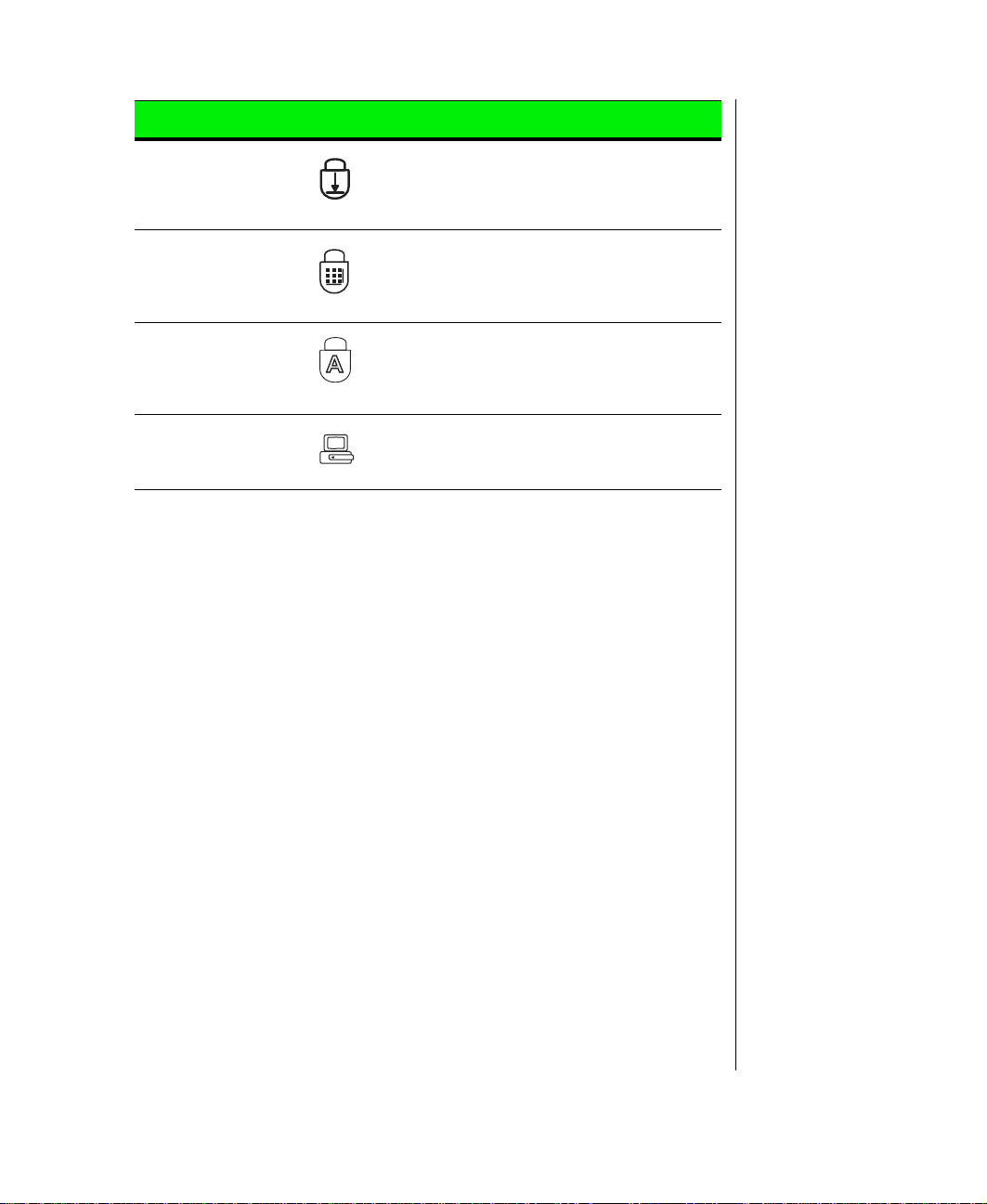
Indicator Icon Description
G.Scroll lock Visible when Scroll Lock is enabled.
H.Pad lock Visible when Pad Lock is enabled.
I. Caps lock Visible when Caps Lock is enabled.
J. System docked Visible when the system is docked.
Chapter 1: Checking Out Your Notebook Computer 9
Page 10
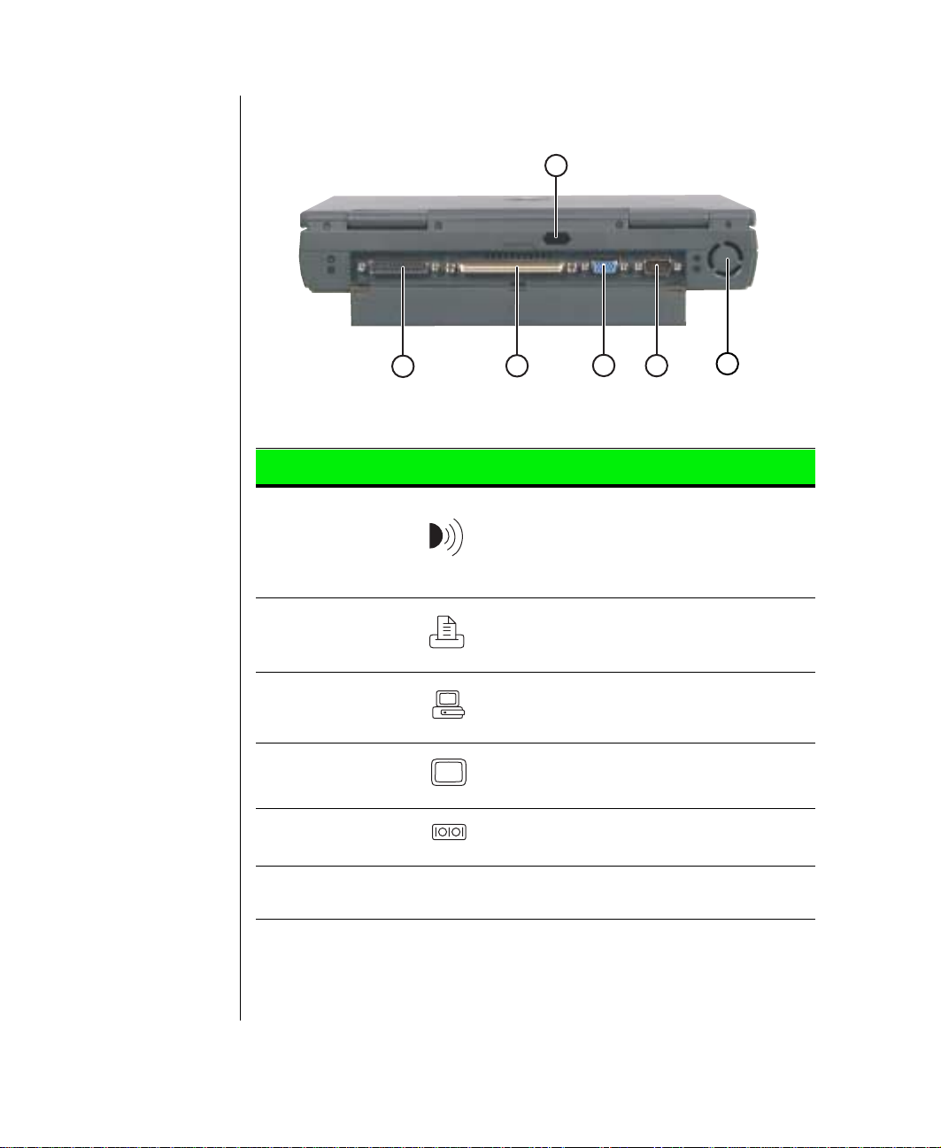
Back ports panel
A
B
C
D
E
F
Port Icon Description
A. Fast IR (Infra-
red) port
B. Parallel port
(LPT1)
C.Docking port Connect an optional docking station to this
D. VGA port Connect the VGA monitor cable to this port.
E. Serial port Connect an optional serial device to this port.
Sends infrared signals bet ween the notebook
and a remote device that uses infrared (for
example, another computer, printer, or other
peripheral). Place infrared devices up to 3
feet (1 meter) apart.
Connect parallel device such as a printer to
this port.
port.
F. Fan intake Pulls air into chassis to keep system compo-
10 Using Your Gateway Solo 2500 Multimedia Notebook
nents cool.
Page 11
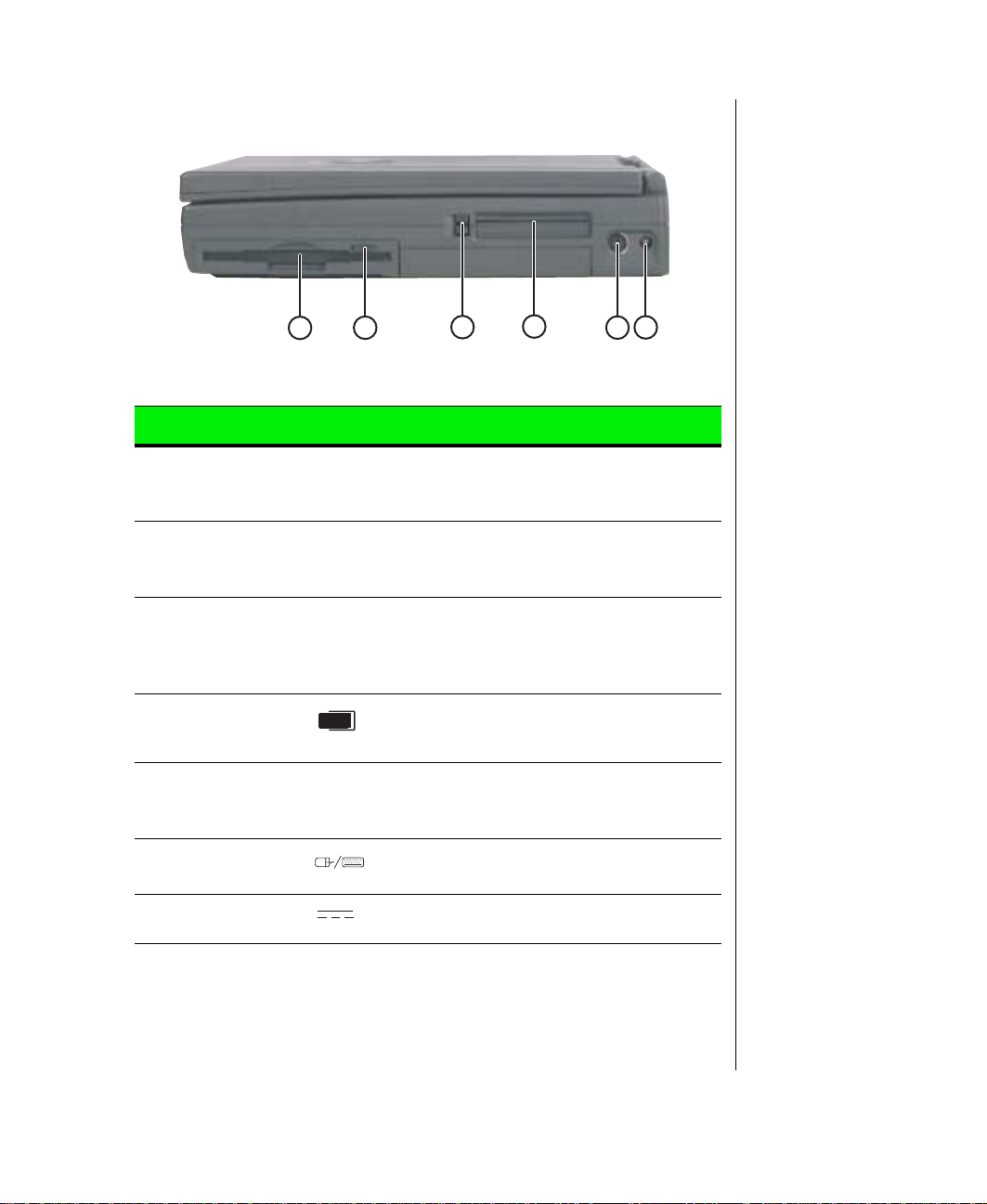
Right side ports and ba ys
A
B
C
D
E
F
Component Icon Description
A. FDD (Floppy
Diskette Drive)/
LS120 drive
B. FDD/LS120
eject button
(Not shown)
LS120 emergency
eject hole
C.PC Card eject
buttons
D. PC Card slots Accepts two Type I or Type II PC Cards or
E. PS/2 port Connect the keyboard, mouse, numeric key-
Either a FDD or an LS120 drive is installed
here. (FDD shown)
Ejects the FDD or LS120 diskette from the
drive. The LS120 button is functional only
when power is on.
Provides manual eject capability to remove a
diskette if power is unavailable. See “Using
emergency eject f o r di sk ette and d isc med ia”
on Page 43.
Push once to release the eject button and
push a second time to eject the PC Card.
one Type III PC Card. (Install Type III PC
Card in the bottom slot.)
pad, or other external device to this port.
F. Power connector Connect the AC power adapter to t his port.
Chapter 1: Checking Out Your Notebook Computer 11
Page 12
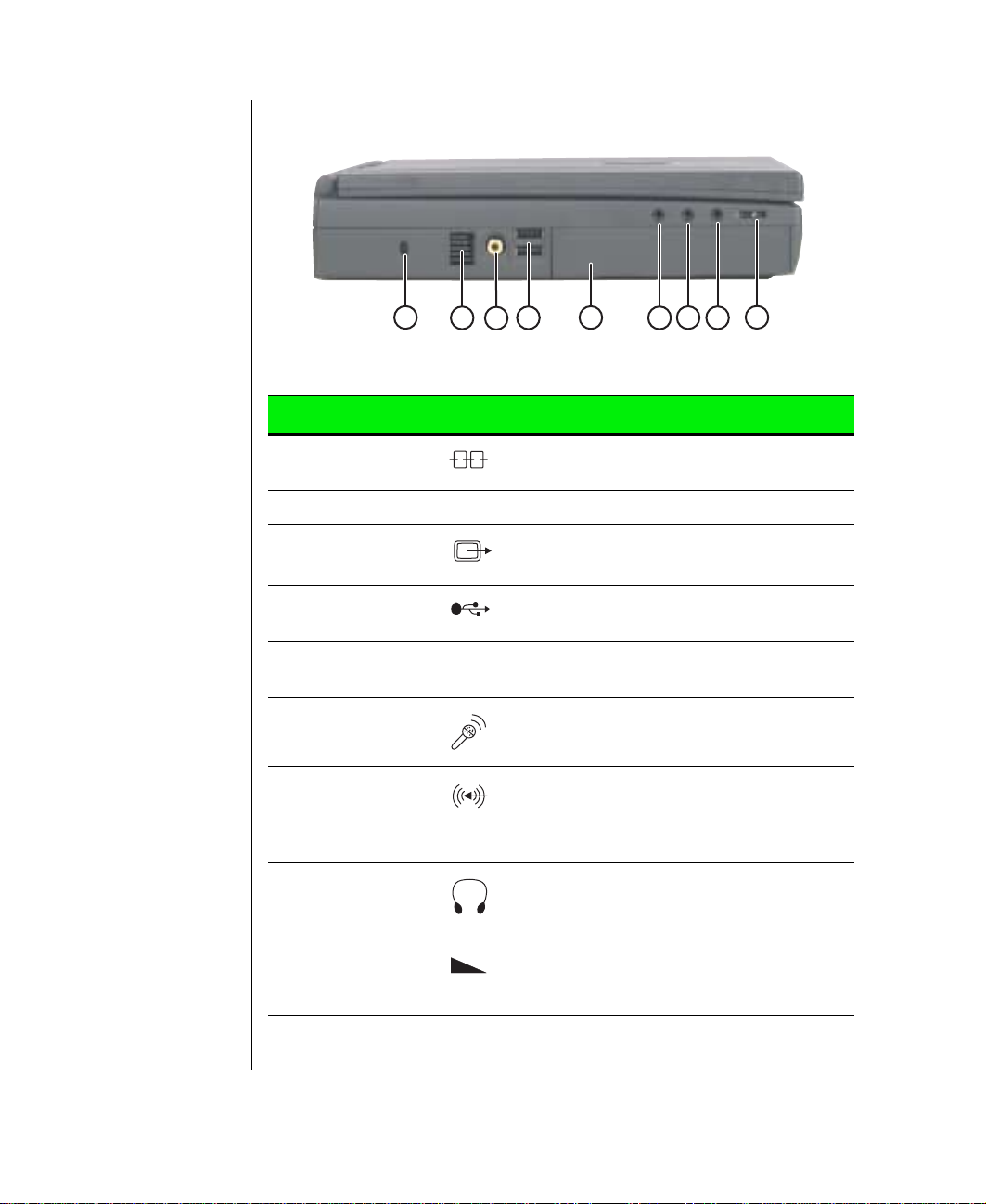
Left side ports and battery bay
A
B
D
C
E
G
F
I
H
Component Icon Description
A. Kensington lock
slot
B. Air outlet port Outlet for air intake to cool components.
C. Composite video
out (TV out)
D. USB (Universal
Serial Bus) ports
E. Battery bay Insert battery into the battery bay to power
F. Mic in Connect an external microphone to this port
G.Audio Line In Connect an external audio input source
Attach Kensington lock into this slot.
Connect a TV, VCR, or video camera to this
port.
Plug optional USB serial devices into these
ports.
your system with a battery.
to record audio. (1/8-inch/3.5-mm jack.)
(computer, stereo, VCR, etc.) to this port to
record or play audio through the notebook
speakers. (1/8 -inch/3.5- mm jack.)
H.Speaker out/
Headphone jack
I. Volume wheel Adjust built-in speaker volume, external speaker,
12 Using Your Gateway Solo 2500 Multimedia Notebook
Connect external speak ers or headphon es to
this port. Supports small unamplified speakers. (1/8-inch/3.5-mm jack.)
and headphone volume. Other port volume levels are controlled by multimedia software.
Page 13
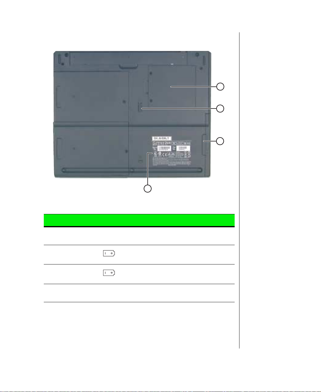
Bottom release latches and memory bay
A
B
C
D
Component Icon Description
A. Memory bay Open the memory bay cover to install/
remove SO-DIMM memory modules.
B. Battery release
latch
C.Battery pack bay Slide ba ttery pack into bay for battery power
D. System identifi-
cation label
Slide the latch to release the battery pack
from the battery pack bay.
and battery charging.
Provides product model number, serial num-
ber, display type, and processor speed.
Chapter 1: Checking Out Your Notebook Computer 13
Page 14

14 Using Your Gateway Solo 2500 Multimedia Notebook
Page 15

Chapter 2:
Getting Started
Getting Your System Running.............................. 16
Installing the battery pack .............................. 16
Connecting the AC power.............................. 18
Starting up your notebook.............................. 19
Page 16
Getting Your System Ru nning
To get the computer started you’ll need to install the battery pack, connect
to AC power, open the LCD panel, and start up the system.
Installing the battery pack
Your notebook is powered by one of the longest-lasting batteries available,
shipped to you partially charged. When you first get started, you may want
to use the AC adapter to fully charge the battery and provide a constant
supply of power while you are checking out some of the notebook features.
If your battery is not installed, you need to install the battery pack and
charge it. You can charge the battery:
♦ When you are using your notebook with the AC adapter
♦ When the system is attached to AC power and in standby or suspend
mode
Note:
Battery life varies
depending on configuration,
power management
settings, and features used.
♦ When the system is attached to AC power and the system is turned off
The notebook can run on a fully charged battery for about 3 to 4 hours. Use
the battery gauge icon in the taskbar or battery gauge in the system
status indicator to track the available battery power. See “Monitoring the
battery status” on Page 59 to learn more about tracking battery status.
Battery life is affected by how much you use the system components such
as the hard drive, CD-ROM drive, LCD display, and other components.
Other factors such as the power management settings affect battery life.
See Chapter 4, “Managing Power Usage” for more information about
power management and monitoring the battery status.
16 Using Your Gateway Solo 2500 Multimedia Notebook
Page 17
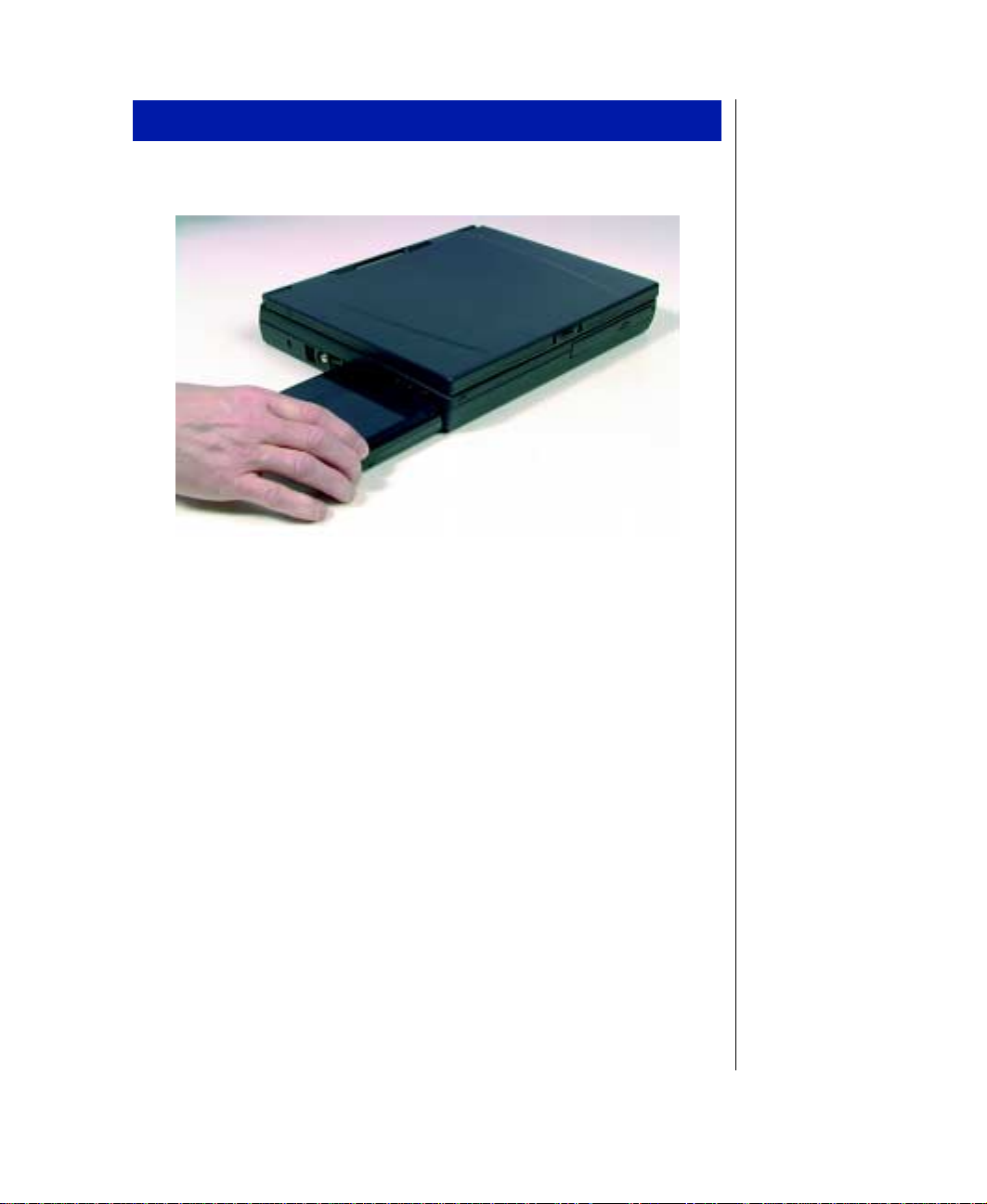
To install the battery pack
1.
Slide the battery pack into the battery pack bay.
2.
Push the battery until it snaps into place.
Chapter 2: Getting Started 17
Page 18
Connecting the AC po wer
Caution!
Replace the power cord if it
becomes damaged. The
replacement cord must be
of the same type and
voltage rating as the
original cord.
Warning!
Do not attempt to
disassemble the AC
adapter. The AC adapter
has no user-replaceable or
user-serviceable parts
inside. The AC adapter has
dangerous voltages that
can cause serious personal
injury or death. Contact
Gatewa y about returning
defective AC adapters.
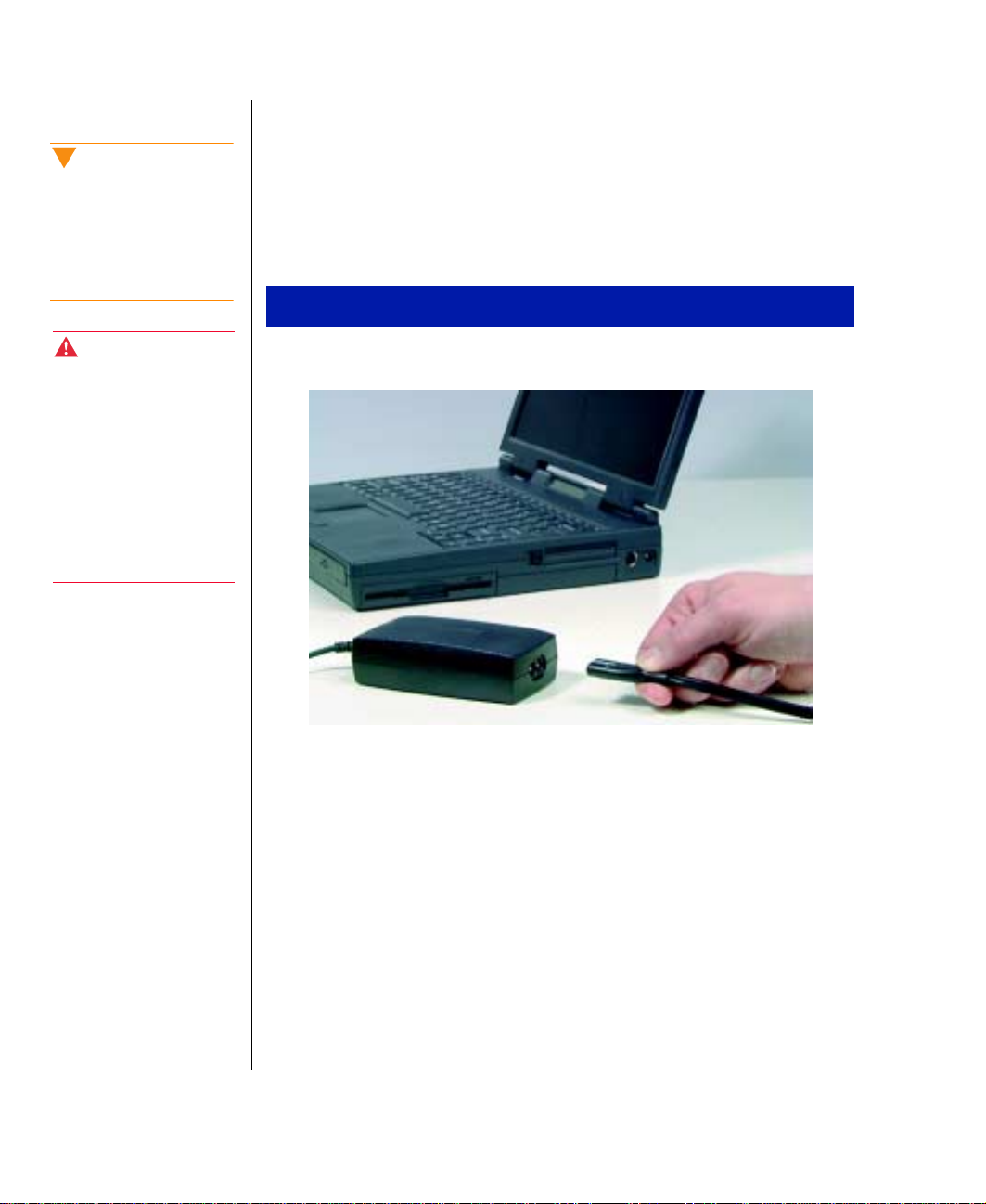
Your AC adapter comes in two parts:
♦ Power cord
♦ AC power adapter
To connect the AC adapter
1.
Connect the power cord to the AC power adapter.
18 Using Your Gateway Solo 2500 Multimedia Notebook
Page 19
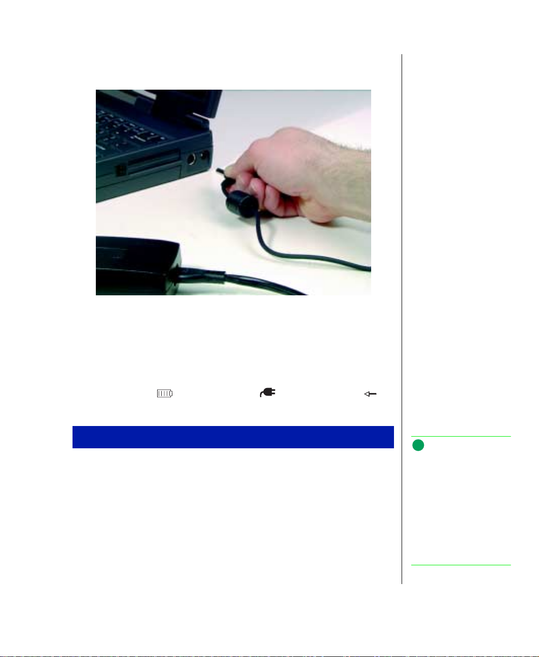
2.
Plug the AC power adapter into the notebook power connector on the
right side of the notebook near the back.
3.
Plug the power cord into an electrical outlet.
Starting up your notebook
Once the battery is installed and the AC power adapter is plugged in you will
see the battery icon , the AC power icon , and the charge icon .
To startup the computer
1.
Slide the LCD panel latch to the right to release and open the LCD panel.
2.
Tilt the LCD panel to adjust for the proper viewing angle.
3.
Press the power button to turn your computer on.
Note:
The power button is preset
to On/Off mode. You can
set it to function either in
On/Off or Standby/Resume
mode using the BIOS setup
program. See “Setting the
power button” on Page 60
for more inf ormation about
changing power button
modes.
Chapter 2: Getting Started 19
Page 20

Note:
This system ships with the
“Auto dim with battery”
feature enabled. A uto dim
cuts LCD power 50% when
your notebook is operating
on battery power. See
“Using the BIOS Setup
Utility” on Page 70 for more
information about changing
the Pow er menu options .
4.
F
+↑
F
Press
N
or
+↓
to change display brightness for suitable viewing.
N
Notebooks with a HPA screen, press
FN+
→ or
FN+
to control
←
display contrast.
To complete the first-time operating system setup
1.
Windows starts and the Regional Settings dialog box opens.
2.
Scroll down the list and select the regional setting.
3.
Click Next. The Keyboard Layout dialog box opens.
4.
Scroll down the list and select the keyboard layout.
5.
Click Next. The User Information dialog box opens.
6.
Enter your Name and Company (optional) in the User Information dialog box.
7.
Click Next. The License Agreement opens.
8.
Scroll through the License Agreement to read it.
9.
Click I accept the agreement, then click Next. The Certificate of Authenticity dialog box opens.
10.
Enter the Product ID number. This number is located on the
Certificate of Authenticity on the cover of the Windows manual.
11.
Click Next. The Start Wizard window opens.
12.
Click Finish. The Time Properties dialog box opens.
13.
Set the Time Zone and Time.
14.
Click OK. The Add Printer Wizard dialog box opens.
15.
Click Next.
16.
Select a printer from the list and click Next.
- OR -
Cancel to skip the printer setup.
click
20 Using Your Gateway Solo 2500 Multimedia Notebook
Page 21

17.
Select the printer port (usually LPT1).
18.
Click Next. The Printer Name dialog box opens.
19.
Name the printer leaving the default name or rename the printer.
20.
Click Next.
21.
Click Yes or No to print a test page.
22.
Click Finish. The Welcome dialog box opens.
Chapter 2: Getting Started 21
Page 22

22 Using Your Gateway Solo 2500 Multimedia Notebook
Page 23

Chapter 3:
Using Your Notebook
Using Your Solo 2500................................................ 24
Using the keyboard..............................................24
Using key combinations......................................25
Using the LCD.....................................................29
Using the pointing device....................................31
Using the audio....................................................39
Using diskette media (3.5" or LS120 diskettes).41
Using disc media (CD-ROM).............................42
Removing and replacing the hard disk drive......44
Using PC Cards ...................................................46
Using the IR port .................................................48
Using the USB ports............................................51
Using McAfee VirusScan ...................................52
Page 24
Using Your Solo 2500
This chapter covers using the components on your computer. Spend some
time getting familiar with the versatility built into your Solo notebook.
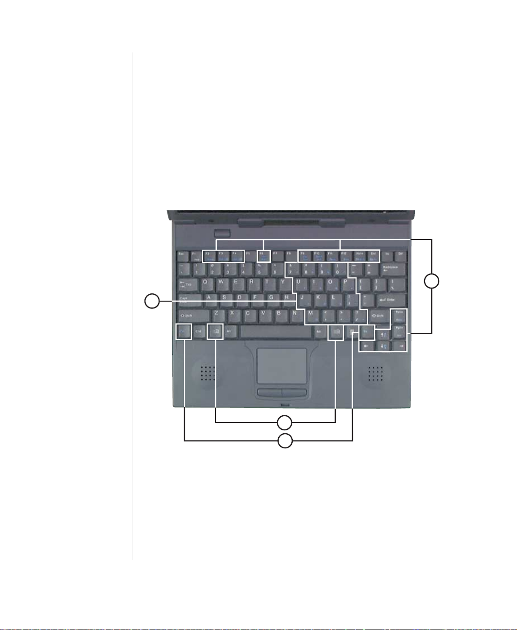
Using the ke yboard
Your notebook features a full-size keyboard that has the full functionality of
a desktop computer keyboard. Many of the keys have been assigned
alternate functions, including shortcut keys for Windows 95, function keys
for specific system operations, and pad lock keys for the numeric keypad.
A
D
24 Using Your Gateway Solo 2500 Multimedia Notebook
C
B
Page 25
Key Action
A. Fn (function)
Combination
keys
B. Fn (function)
keys
C.Windows logo
key
D. Numeric keypad
Press
(blue) to perform a specific function. For example,
FN+F2
Press
as
Press to activate the Windows
Press
key plus one of the Fn Combination keys
F
N
shows the Pop-up status display.
key plus another Fn Combinatio n key (such
F
N
F2, F3, F4
, etc.) to perform a specific function.
Start
to activate the numeric keypad.
FN+F9
button menu.
Using key combinations
For normal key functions:
♦ Press the key to get numerals, punctuation marks, and lower case
letters.
♦ Press the key together with the
upper case letters.
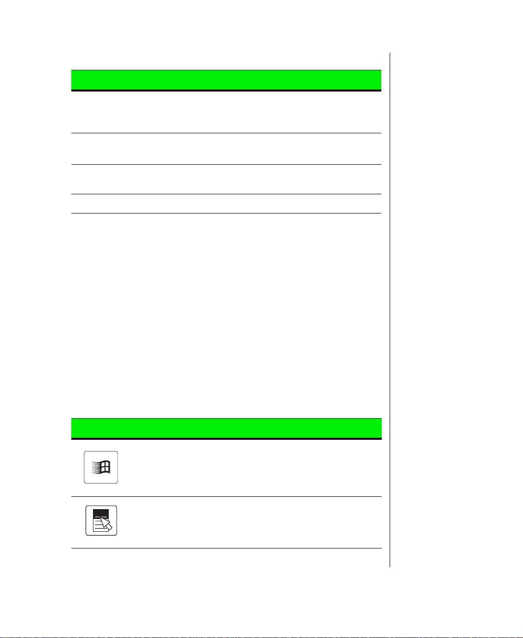
Special keys
S
key to get symbols and standard
HIFT
The following keys help you use shortcuts when working with some
software:
Key Descripti on
Use this key to disp lay th e Windows Start menu.
Use this key to provide quick access to shortcut menus
and help assistants in Windows.
Chapter 3: Using Your Notebook 25
Page 26
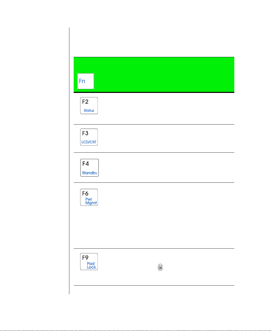
Function keys
Press the
F
key together with one of the following keys (with blue letters)
N
to get these “on-the-fly” functions:
Key
Description
Combination
+
Displays the power st atus display for the Pop-up Status
Display pro gr am in th e upper le ft corner of the Wi ndo ws
95 desktop. Press the key combination again to make
the display disappear. See “Pop-up status display” on
Page 60.
Toggles between the L CD displa y, external monitor, bo th
displays at the same time, or TV display (NTSC or PAL
format) as the active display. See “Using the LCD” on
Page 29.
Places the system in Standb y mo de. See “Using the
suspend and standby modes” on Page 61 f o r mo re information about the Standby mode.
Makes temporary changes to the power management
(PM) mode settings by toggling the setting options:
•PM ON - enables power management with AC or battery power
•PM DC - enables power management when the notebook is using battery power only.
•PM OFF - disables power management.
The selected option is not saved when the system is
turned off. The power management settings selected in
the BIOS setup program are effective when the system
is restarted.
26 Using Your Gateway Solo 2500 Multimedia Notebook
Enables the Pad Lock function so you can use the
numeric keypad.
The Pad Lock icon stays lit while this function is
enabled. Press the key combination again to make the
display disappear.
Page 27

Key
Combination
+
Description
In some progr am s you can scroll through large v o lum es
of text.
The Scroll Loc k i con stays lit as long as th is fu nction
is enabled.
In some programs this key combination pauses the display when text is scrolling very quick ly. Press any key to
continue the text flow.
In some programs this key combination breaks text
scrolling in a DOS screen.
Prints the screen if a printer is connected to your notebook (DOS only). In Windows, this key combination puts
the screen content into the clipboard. You can then paste
it into a program such as Paint to display or print it.
SysRq (System Request) is reserved for certain applications such as in some DOS programs.
In some programs this key combination will send you to
the starting point of your text.
In some progr ams this k ey combinatio n sends y ou to the
end point of you r text.
Increases LCD brightness and displays the brightness
meter for the Popup Status Display reflecting the
changes. Use the
display disappear
+F2 key combination to make the
F
N
Chapter 3: Using Your Notebook 27
Page 28

Key
Description
Combination
+
Decreases LCD brightness and displays the brightness
meter for the Popup Status Display reflecting the
changes. Use the
display disappear.
(HPA display only)
Increases LCD contrast and displays the contrast meter for
the Popup Status Display reflecting the changes. Use the
+F2 key combination to mak e the display disappear.
F
N
(HPA display only)
Decreases LCD contrast and displays the contrast meter
for the Popup Status Display reflecting the changes. Use
+F2 key combination to mak e the displa y disappear.
the
F
N
+F2 key combination to make the
F
N
Pad lock keys
FN+F9 (PAD L
Press
the keyboard will function like a numeric keypad. Press
keyboard back into standard mode.
) keys to activate the keypad. The keypad section of
OCK
FN+F9
to put the
28 Using Your Gateway Solo 2500 Multimedia Notebook
Page 29

Using the LCD
Your notebook features a built-in, backlit, color liquid crystal display
(LCD). The LCD uses either thin-film transistor (TFT) or high
performance addressing (HPA) technology that provides sharp resolution
and brilliant colors. See the table below for the resolution your
configuration provides:
12.1 HPA 12.1 TFT 13.3 TFT
Maximum resolution setting
(pixel column x pixel row)
Maximum color depth setting 24 bit 24 bit 16 bit
800 x 600 800 x 600 1024 x 768
In addition to using your LCD panel for display, you can also attach an
external monitor for presentations and other multimedia purposes. See the
next sections to learn about setting up external displays.
Setting up the composite video (TV) out port
The composite video out port lets you view your notebook's display on a
TV screen or record to a VCR. This option is typically used with largescreen TVs to give presentations and for other multimedia needs.
To setup and connect the computer to a TV or VCR
1.
Click Start, Settings, then Control Panel. Double-click the Display icon
and click the
2.
Change the desktop area (display resolution) by sliding the Desktop area
slider to adjust pixel resolution to
Settings tab in the Display Properties window.
640 x 480.
Note:
TV screen display
resolution will not be as
clear as an external monitor
because of the TV screen
display limitations.
3.
Change the font size to Large Font.
4.
Click Apply, then OK. Windows changes the display settings.
5.
Next, connect one end of a video cable to the composite video (TV)
out port on the left side of the notebook and the other end to the video
in connector on the television or VCR.
Chapter 3: Using Your Notebook 29
Page 30

6.
Press
FN+F3
to change the active display to LCD only, LCD and
monitor, or TV only.
If the display is distorted, check to see if the BIOS setting is correct for
NTSC or PAL (NTSC is primarily used in the United States). See “About
the BIOS Setup Utility” on Page 70 for more information about changing
the TV Mode.
Setting up an external computer monitor
You can connect an external computer monitor to your notebook through
the VGA port on the back of your notebook. If you are using an optional
docking station, you can also connect an external computer monitor to the
docking station VGA port.
To connect the computer to an external monitor
1.
Connect one end of a VGA cable to the VGA port on the back of the
notebook, and the other end to the video connector on the monitor.
2.
Press
FN+F3
to change the active display from LCD only, to LCD and
monitor, or monitor only. Continue changing the display options until
you get the desired display.
Depending upon the external monitor you are using, you may have to lower
the video resolution to 640 x 480. Refer to your monitor manual to find out
its display resolution capabilities.
To change the display resolution for an external monitor
1.
Right-click the Monitor icon in the taskbar tray (right bottom corner).
2.
Select the desired resolution. The screen resolution changes.
Monitor icon does not appear on the taskbar and you want to have it
If the
display there, then right-click on the desktop, the
box opens. Click the
Monitor icon appears in the taskbar tray.
30 Using Your Gateway Solo 2500 Multimedia Notebook
Display Properties dialog
Settings tab, then click Show settings icon on taskbar. The
Page 31

Using the pointing device
Your system came with one of two possible pointing devices:
♦ Enhanced EZ Pad
- OR -
♦ EZ Point
Like a mouse, these pointing devices control the cursor movements on the
display.
Also, you can use an external mouse. Connect the mouse device to the PS/2
port, the USB port, or the serial port. Review this section to find out more
about these pointing device options.
™
™
stickpoint
TouchPad
Using the Enhanced EZ Pad TouchPad
The Enhanced EZ Pad TouchPad provides you with fast and easy
navigation in large documents, spreadsheets, emails, and when using the
Internet. You can scroll, zoom, autoscroll, and pan with the convenience of
a wheel mouse in the space saving form of a touchpad that is integrated into
your Solo notebook. Scrolling capabilities are available in some Windows
applications including Microsoft Office.
A
B
Chapter 3: Using Your Notebook 31
Page 32

A.
EZ Pad (TouchPad)
B.
EZ Pad buttons (mouse buttons)
This touchpad uses one surface for both mouse and wheel functions, which
means you can perform all of the wheel mouse functions without using
mechanical buttons. The Enhanced TouchPad uses the simple movement of
one, two, or three fingers to perform the left, middle, and right mouse
button functions. These intuitive movements make it easy to learn and use
this pointing device.
This touchpad also uses the Smart Edges technology to let you to continue
to move the cursor and drag objects, even when your finger reaches the
edges of the touchpad. This lets you move horizontally and vertically
without being constrained by the size of the touchpad. This is especially
useful when dragging objects and selecting text because there is no need to
remove your finger until the action is completed.
Mouse and TouchPad action equivalents
All of the mouse and wheel functions are illustrated and described in the
table shown below.
Mouse Action TouchPad Action
Move cursor Slide finger
32 Using Your Gateway Solo 2500 Multimedia Notebook
Page 33

Mouse Action TouchPad Action
Left button click
Middle button
click
Right button clic k
Left button
double click
Left button drag Tap and drag
Tap one finger
Tap 2 fingers
Tap 3 fingers
Double tap 1 finger
Smart Edges Tap and drag. When your
finger stops at an edge of the
TouchPad, the cursor
continues moving across the
screen until you lift or move
your finger away from the
edge of the TouchPad.
Chapter 3: Using Your Notebook 33
Page 34

Mouse wheel equivalents
Wheel Mouse
Action
Rotate the
mouse wheel
(roller)
CTRL + rotate
the wheel
SHIFT + rotate
the wheel
Click on the
wheel (middle
mouse button)
TouchPad
Equivalent
Scrolling Up/Down
Put finger on right edge of
the touchpad and move up/
down.
Zoom in/out
Changes the magnifi cation of
the document.
Data zoom
Jump to a hyperlink or return
to previous Web sites using
Internet Explorer.
Expand or collapse menu
trees in Wi ndows Explorer.
Autoscroll
Tap with two fingers to drop
Origin
an
moves away from this origin,
the document scrolls. The
direction and distance from
the origin controls the scrolling direction and speed.
Any subsequent keystroke,
mouse click, or roller action
terminates the operation.
:
:
:
mark. As the cursor
:
Press the wheel.
(middle mouse
button)
34 Using Your Gateway Solo 2500 Multimedia Notebook
Panning
Same function as Autoscroll,
except that the operation
terminates when the fingers
are lifted
:
Page 35

Advanced mouse and TouchPad action equiv alents
Mouse Action TouchPad Action
Middle button
double click
Right button
double click
Middle button
drag
Right button
drag
Changing touchpad properties
Double tap 2 fingers
Double tap 3 fingers
Slide 2 fi ngers. (2nd finger
does not need to stay on the
pad)
Drag 3 fingers. (2nd and 3rd
finger do not need to stay on
the pad)
You can customize the Enhanced EZ Pad. Use the following instructions to
change EZ Pad properties such as pointer size, button assignments, cursor
speed and acceleration, scrolling speed, edge motion, and others.
To customize the Enhanced EZ Pad
1.
Double-click the icon in the task tray (bottom right corner) to access the touchpad properties.
Chapter 3: Using Your Notebook 35
Page 36

2.
Click the tab of your choice in Mouse Properties dialog box to access
and customize various aspects of the touchpad functionality.
Click , then
MouseWare Help to find more helps about using the touchpad.
Using the EZ Point (optional)
The optional EZ Point pointing device provides an easy way to move the
cursor across the screen and navigate through software. The EZ Point
consists of a stick located on the keyboard between the G and H keys and
two click buttons located below the spacebar on the keyboard.
A
A.
EZ Point
B.
EZ Point select buttons (mouse buttons)
36 Using Your Gateway Solo 2500 Multimedia Notebook
B
Page 37

To use the EZ point
1.
Place your hands in the typing position and press the EZ Point (A) in
the direction you want to move the cursor.
2.
Press the EZ Point select buttons (B) located below the spacebar to
select as you would with a mouse.
Changing EZ Point properties
You can customize the EZ Point. Use the following instructions to change
EZ Point properties such as pointer size, button assignments, cursor speed
and acceleration.
To customize the Enhanced EZ Point
1.
Click Start, Settings, then Control Panel. The Control Panel opens.
2.
Double-click the Mouse icon. The Mouse Properties dialog box opens.
3.
Click the tab of your choice in Mouse Properties dialog box to access
and customize various aspects of the EZ Point functionality.
Chapter 3: Using Your Notebook 37
Page 38

Replacing the EZ Point cap
The cap on the end of the EZ Point is removable. If the cap becomes worn,
remove the cap from the stick and replace it with one of the spares that
comes with your notebook.
Using an external mouse or keyboard
You can attach an external mouse or keyboard to the notebook using the PS/2
port, the USB port, or the serial port. The optional docking stations also have
ports for external connections.
It is not necessary to shut down the system to connect an external PS/2
mouse or keyboard. Just connect it to the port and start to work.
If the touchpad or stickpoint drivers do not support the external mouse, then
refer to the mouse documentation and follow the installation instructions.
38 Using Your Gateway Solo 2500 Multimedia Notebook
Page 39

Using the audio
Your system comes with lots of flexibility for using audio. It provides 16-bit
stereo audio with SoundBlaster Pro capability. You can record audio for
presentations, attach voice messages to your e-mail, listen to audio CDs,
and use it for many other multimedia applications. This section tells you
more about using audio.
Adjusting the volume
There are numerous ways to adjust audio input and output on your Solo
notebook computer. The Volume Control Wheel on the left side of the
system controls the speaker out port and the internal system speakers. The
volume level for other ports is controlled by the multimedia software.
To adjust playback and recording volume levels
1.
Click Start, Settings and Control Panel. Double click the Multimedia icon.
The
Multimedia Properties dialog box opens.
2.
Click the Audio tab.
3.
Set the Playback and Recording levels to your preference.
To “quick-adjust” volume controls
1.
Double-click the Speaker icon (bottom right-hand corner) to open the
Volume Control dialog box.
A
Volume Control dialog box opens. It contains volume and balance
controls for master volume control, CD audio, wave, synthesizer, line,
microphone and 3D Enhanced settings.
Chapter 3: Using Your Notebook 39
Page 40

2.
Slide the various volume and balance controls to suit your listening requirements.
Making an Audio Recording
Note:
Connecting an external
microphone will disable the
built-in microphone.
To make an audio recording, use the built-in microphone or connect an
external microphone to the Mic port on the left side of your notebook.
To make an audio recording
1.
Click Start, Programs, Accessories, Multimedia, then Sound Recorder. The Sound Recorder opens.
2.
Click Edit, then Audio Properties to set or check record volume levels.
3.
Click OK.
4.
Click the ● (Record) button. Recording starts.
5.
Click the ■ (Stop) button. Recording stops.
6.
Click File, then Save As.
7.
Name the recording.
8.
Click Save.The recording is saved.
40 Using Your Gateway Solo 2500 Multimedia Notebook
Page 41

To play back a recording in Media Player
1.
Click Start, Programs, Accessories, Multimedia, then Media Player. The Media Player opens.
2.
Click File, then Open. The Open dialog box appears.
3.
Select the file to play back.
4.
Click Open.
5.
To play the file, click the (Play) button.
6.
To stop the file, click the ■ (Stop) button.
Using diskette media (3.5" or LS120 diskettes)
Your system has either a standard 3.5" diskette drive or an LS120 drive
(optional). If your system has the 3.5" diskette drive, use 3.5" diskettes with
up to 1.44 MB capacity. The LS120 drive works just like any other diskette
drive, except that it can read and write to the standard 3.5" diskettes (720
KB/1.44MB) or to LS120 diskettes (SuperDisk™) that hold up to 120 MB
of data.
Caution!
Do not expose diskettes to
water or magnet ic fiel ds .
Exposure cou ld dama ge the
data on the diskette.
Note:
If power is unavailabl e and
you need to remove a
diskette, you can manually
eject the diskette. See
“Using emergency eject for
diskette and disc media” on
Page 43.
Chapter 3: Using Your Notebook 41
Page 42

Using disc media (CD-ROM)
Your system has a CD-ROM drive. This section describes some of the ways
to use CD-ROM media.
To insert a CD
1.
Press the Eject button. The CD drive tray opens.
2.
Insert the CD. Press down carefully on the CD to ensure it snaps under
the clips that holds the CD in the tray.
Be sure to place the CD in the tray so that the label side is facing up. If
the disc has two playable sides, place the disc so that the name of the
side you want to play (A or B) is facing up.
3.
Press the Eject button to close the tray.
To access information on the CD drive
1.
Double-click the My Computer icon. The My Computer window opens.
2.
Double-click the CD-ROM drive icon.
Playing an audio CD
The CD-ROM accepts standard CD data discs, music CDs, and photo CDs.
You can play and control an audio CD using the CD Player application in
Windows.
1.
Insert an audio CD. See “To insert a CD” on Page 42. After a few
seconds, the CD-ROM starts playing automatically.
42 Using Your Gateway Solo 2500 Multimedia Notebook
To play an audio CD
Page 43

2.
Click the CD Player taskbar button to use the CD Player software.
- OR -
If the CD did not auto-start, then click
Multimedia, and CD Player to start the CD Player software.
3.
Slide the mouse pointer slowly over the control buttons on the CD
Start, Programs, Accessories,
Player software to get familiar with each button function.
You can change music tracks, view playing times, control the volume,
set preferences, define a play list and even set the system to
continuous or random play using this dialog box.
4.
Control audio play as desired.
Using emergency eject for diskette and disc media
You may encounter a circumstance when it is not possible or convenient to
open the LS120 or CD-ROM drive using the eject button (for example,
when the computer is shut down).
Chapter 3: Using Your Notebook 43
Page 44

To use the emergency eject
1.
Carefully insert a stiff wire (such as a straightened, heavy-duty paper
clip) into the emergency eject hole until you feel resistance.
A
A.
Emergency eject hole
2.
Gently press a bit harder until the drive tray slides out (CD-ROM) or until the diskette ejects.
3.
(CD-ROM only.) Gently grasp the front of the tray and pull it out.
Removing and replacing the hard disk drive
Caution!
You can remove the hard disk drive (HDD) from your notebook to swap to a
second HDD.
If you decide to add a new HDD, then use the documentation that comes
Do not expose the hard
drive to liquid or magnetic
fields. Expo sure co uld
damage the data on the
hard drive.
44 Using Your Gateway Solo 2500 Multimedia Notebook
with the HDD to prepare the hard drive for use.
1.
Save all work.
2.
Click Start, Shut Down, Shut down your computer?, then click OK.
3.
Close the LCD lid.
4.
Disconnect the AC power.
5.
Remove the battery. See “To remove the battery pack” on Page 57.
To remove the hard disk drive
Page 45

6.
Turn the notebook over and remove the screw that secures the HDD.
7.
Slide the HDD out and lift up.
Chapter 3: Using Your Notebook 45
Page 46

To replace the hard disk drive
1.
Make sure the power is turned off, AC disconnected, and battery is removed.
2.
Press into the bay tracks and slide the HDD firmly into the bay.
3.
Secure the HDD with the screw.
4.
Turn the notebook over and reconnect the AC adapter and replace the
battery pack. See “Connecting the AC power” on Page 18.
5.
Start up the system when you are ready to use it.
6.
If this is a first time installation, then follow the information that
accompanied the HDD to prepare it for use.
Using PC Cards
Your notebook’s PC Card slots (also known as PCMCIA card slots) are
located behind the PC Card doors on the right side of your notebook (see
“PC Card slots” on Page 11). These slots accept PC Card 16, PC Card 32
(CardBus) or Zoomed Video cards.
Your notebook is configured to automatically accept most PC Cards. If you
ordered your notebook with a modem, then the modem drivers are already
installed.
You do not need to restart your notebook when changing most cards
because your notebook supports “hot-swapping.” This means that you can
usually insert a PC Card and the system recognizes it without shutting down
the notebook. If your PC Card does not work when hot-swapping, refer to
the PC Card manufacturer’s documentation for further information.
46 Using Your Gateway Solo 2500 Multimedia Notebook
Page 47

To insert a PC Card
1.
Insert the PC Card with the label face up.
2.
Slide the card firmly into the PC Card slot. When the card is installed
correctly, the computer emits a two-toned beep.
3.
Follow the Windows Setup Wizard installation steps the first time you
insert a PC Card. Operate the device as recommended in the PC Card
manufacturer’s manual.
Note:
If you are using a Type III
PC Card or Zoomed Video
card, it must be inserted
into the bottom slot.
To remove a PC Card
1.
Click the PC Card icon in the taskbar.
2.
Click the card that you want remove.
3.
Click Stop. A screen appears stating that you may safely remove the device.
4.
Click OK.
Chapter 3: Using Your Notebook 47
Page 48

5.
Press the PC Card eject button, located to the left of the PC Card slot,
to release the eject button.
6.
Press the PC Card eject button a second time to eject the PC Card.
7.
Press the PC Card eject button to reset back into the notebook.
Using the IR port
The IR (infrared) port built into the back of your notebook (see “Fast IR port”
on Page 10) uses infrared technology to send and receive signals between the
notebook and a remote device equipped with an IR port. A variety of desktop
computers, printers, and other peripherals are IR-equipped. Use the
manufacturer’s documentation to setup a remote IR device.
Your notebook shipped with the IR port enabled. If you do not use the IR
port and need to make more resources (IRQs) available for other commonly
used devices, then use the following steps to disable the IR port.
48 Using Your Gateway Solo 2500 Multimedia Notebook
Page 49

To disable the IR port
1.
Remove any PC Card from the PC Card slots.
2.
Click Start, Settings, then Control Panel. The Control Panel opens.
3.
Double-click the System icon. The System Properties dialog box opens.
4.
Click the Device Manager tab.
5.
Click + beside Infrared. The Built-in Infrared port on laptop or desktop appears in the list.
6.
Double-click Built-in Infrared port on laptop or desktop. The Built-in Infrared
port on laptop or desktop Properties dialog box opens.
Chapter 3: Using Your Notebook 49
Page 50

7.
Click to add a check in the checkbox beside Disable in this hardware
profile.
8.
Click OK.
9.
Click OK under the Device Manager tab.
10.
Next, double-click the Infrared icon located in the Control Panel. The
Infrared Monitor dialog box opens.
11.
Click the Options tab.
50 Using Your Gateway Solo 2500 Multimedia Notebook
Page 51

12.
Click to remove the checkbox beside Enable infrared communication on: COM2.
13.
Click OK.
Using the USB ports
USB is a new type of serial interface that serves as a single-port alternative
to connecting devices that traditionally have required their own specific
ports—such as mice, joysticks, keyboards, scanners, video conferencing
cameras, and speakers.
To use, connect the USB-compatible peripheral into the USB port (see
“USB ports” on Page 12). The USB automatically installs and configures
the necessary drivers and the system resources.
Chapter 3: Using Your Notebook 51
Page 52

Note:
We recommend you always
scan diskettes that you are
introducing to your system.
Using McAf ee VirusScan
McAfee VirusScan is a software program installed to help you protect your
system from computer viruses. Each time you start your system, McAfee
VirusScan scans your hard drive for computer viruses that could be
potentially harmful to your system.
A computer virus is a software program that attaches itself to another
program on the computer, and spreads from one program to another. Some
viruses can go unnoticed for long periods of time because they are tied to a
certain time or date before they become active. If transmitted unnoticed,
viruses can damage data, cause computers to crash, or display bothersome
or offensive messages. Avoiding computer virus infection is important, and
McAfee VirusScan helps you protect your system from computer viruses.
If you are using floppy diskettes to transfer information to your system, you
can run the McAfee VirusScan software on the diskette to check it before
copying files from it to your system.
To scan a diskette
1.
Place the diskette in the floppy drive.
2.
Click Start, Programs, McAfee VirusScan, and VirusScan.
3.
Change the C:\ drive setting to A:\ and click All Files.
4.
Click the Scan Now
52 Using Your Gateway Solo 2500 Multimedia Notebook
button to begin scanning the diskette.
Page 53

Updating McAfee VirusScan
Because new viruses are continuously being introduced in the computer
world, a message appears approximately every six months reminding you to
update your version of McAfee VirusScan. Updating your version of
McAfee VirusScan is important, because it keeps your virus protection
current.
If you have a modem, an analog phone line, and a subscription to an
Internet service provider you can update McAfee VirusScan software.
Click the
Update button and follow the on-screen instructions to complete
the update process.
Note:
You must have a modem
installed in your system and
properly connected to a
phone line to access the
Internet.
Chapter 3: Using Your Notebook 53
Page 54

54 Using Your Gateway Solo 2500 Multimedia Notebook
Page 55

Chapter 4:
Managing P ower Usage
Maximizing Power Management ......................... 56
Charging the battery pack .............................. 56
Using the battery............................................. 58
Monitoring the battery status ......................... 59
Setting the power button ................................ 60
Using the suspend and standby modes .......... 61
Maximizing the battery life............................ 63
Page 56

Maximizing P ower Management
Your system has many ways to tailor power management and maximize
battery operating time to best fit how you use your notebook. Find out more
in this chapter about charging and using the battery pack, changing the
power button settings, using Standby, Suspend, and other notebook settings to
maximize battery power.
Charging the b attery pack
The battery must be installed in the notebook and connected to an AC
power source to charge. You can charge the battery in the following modes:
♦ When you are using your notebook with the AC adapter
♦ When the system is attached to AC power and in standby or suspend
mode
♦ When the system is attached to AC power and the system is powered
off
You can also purchase an external battery charger or an airplane/automobile
adapter from Gateway Add-Ons. The external charger can charge an
additional battery while charging a battery in your notebook. The airplane/
automobile adapter lets you power your notebook and charge your battery
when an AC outlet is not available.
1.
Install the battery pack in the computer. See “To install the battery pack” on Page 17.
2.
Connect the AC power to the computer. See “Connecting the AC power” on Page 18.
56 Using Your Gateway Solo 2500 Multimedia Notebook
To charge a battery pack
Page 57

Swapping the battery pack
Battery packs can be “warm-swapped”. This means you can change battery
packs while in Suspend mode (Windows 95) or Standby mode (Windows
98).
The backup battery that supports warm swapping has a limited power
supply (about ten minutes). Make the battery swap quickly to conserve the
backup battery power.
To remove the battery pack
1.
Save all work.
2.
If you are using Windows 95 or NT click Start on the taskbar, then
Suspend to put the system into suspend mode.
- OR -
If you are using Windows 98 click
Down, Standby, then OK to put the system into standby mode.
Start on the taskbar, then click Shut
- OR -
Shut down the system.
3.
Close the LCD panel and turn your notebook over.
4.
Slide the battery release latch to release the battery pack.
Chapter 4: Managing Power Usage 57
Page 58

5.
Hold the latch forward and slide the battery pack straight out from the notebook.
See “To install the battery pack” on Page 17 for battery pack installation
instructions.
Using the battery
Note:
Battery life varies
depending on configuration,
power management
settings, and features used.
Your notebook can run on a fully charged battery for about 3 to 4 hours,
depending on the type of battery you have and how you use your notebook.
Lithium Ion (Li-ion) batteries provide a longer battery life than Nickel
Metal Hydride (NiMH). Under normal operating conditions, Li-ion
batteries have about 600 charge cycles and NiMH have about 400 charge
cycles before they require replacement.
Battery life is affected by how much you use the system components like
the hard drive, CD-ROM drive, LCD display, or other components. For
example, battery life is reduced by using a screen saver rather than the
suspend function. Battery life is also reduced by playing an audio CD while
using a word processor.
Other factors like the power management settings affect the battery life. See
“Maximizing the battery life” on Page 63 for more information about
power management.
58 Using Your Gateway Solo 2500 Multimedia Notebook
Page 59

Battery learning software
About once a year you will need to run the Battery Learning Software
to recalibrate the battery gauge. The learning cycle increases the battery
gauge accuracy and should be run because the gauge accuracy changes over
time.
Because the learning cycle can take as long as 16 hours per battery, we
suggest you start the Learning Cycle program and run it overnight.
To perform a learning cycle on the battery pack
1.
Insert the battery into the battery bay. See “To install the battery pack”
on Page 17 for battery pack installation instructions.
2.
Plug the AC adapter into the notebook and an AC outlet.
3.
Insert the Battery Learning Cycle diskette in the A:\ drive.
4.
Start up your notebook. The Learning Cycle software starts.
5.
Follow the onscreen directions for the battery learning software.
Note:
Removing the battery or
disconnecting the AC
power will interrupt the
learning cycle. If the
learning cycle is
interrupted, it must be
restarted from the
beginning to properly
condition the battery.
Monitoring the battery status
There are many ways to track your battery status. Use any one of the
following battery indicators to track the battery power level.
Battery gauge icon
This icon appears in the taskbar tray (bottom right corner) of the Windows
desktop. Double-click the
The Battery Meter window tells you what the current power source is and
the total battery power remaining.
Battery icon to open the Battery Meter window.
Chapter 4: Managing Power Usage 59
Page 60

Battery gauge system indicator
This icon appears in the system status indicator panel. See “System Status
Indicators (LCDs)” on Page 8 for more information about the icon status
indicators.
P op-up status display
This “pop-up display” provides information about the battery charge and
power status.
FN+F2
Press
of the LCD. The menu displays status information in the following order:
1.
2.
3.
4.
(status key) to display the pop-up menu in the upper left corner
The 1st line shows battery charge status percentage where 100%
represents a fully charged battery. If the battery level is low, a warning
icon appears.
The 2nd line indicates the current power management setting (OFF, ON, or DC).
The 3rd line shows the current power source (AC ON or AC OFF).
The 4th line displays the current BIOS used on the system.
The menu stays open for about ten seconds.
Setting the power button
You can change the Power Button Mode in the BIOS setup program from
On/Off to Standby/Resume. See “Using the BIOS Setup Utility” on Page
70 for more information about accessing the BIOS Power menu settings to
change the Power Button Mode.
Refer to the next section “Using the suspend and standby modes” on Page
61 for more information about using the Suspend and Standby modes.
60 Using Your Gateway Solo 2500 Multimedia Notebook
Page 61

Using the suspend and standby modes
Setting the system to the Suspend (Windows 95 and NT) or Standby
(Windows 98) mode helps conserve battery power without turning the
system power off, lets you leave software applications running, and lets you
“awaken” the system without going through the startup process.
You may be using Windows 95, Windows 98, or Windows NT operating
system (OS) on your notebook. Each OS handles the system modes
differently. Use the table below to learn the mode differences in each OS.
System
Definition Operating
mode
Suspend
(“Sleeping
state”)
Resume “Awakens” system from Suspend
*
Sleep
Causes the system to remove power
from most devices except RAM
(memory).
Pressing the powe r button resumes
power to the notebook.
For example, if you have a program
running and you place the notebook
into Suspend mode, when the system
is brought out of Suspend mode the
software will still be operating.
mode. Restores power to notebook.
Causes the:
•CPU clock to stop
•Video controller to power down
•Hard disk to power down
•Input/output controller to power
down
•Audio to power down
Any activity on the keyboard, mouse,
or a modem ring brings the notebook
to full power.
system
Windows 95
Windows NT
Windows 95
Windows NT
Windows 95
Note:
*Set the Sleep settings in
the BIOS setup program.
The system auto-starts
sleep mode based on the
sleep and timeout settings.
See “Using the BIOS Setup
Utility” on Page 70 for more
information about changing
settings.
Standby
(“Sleeping
state”)
Resume “Awakens” system from Standby
Equivalent to the Suspend mode in
Windows 95
mode. Restores power to notebook.
Windows 98
Windows 98
Chapter 4: Managing Power Usage 61
Page 62

Suspend in Windows 95 and NT
Windows 95 and NT uses Suspend mode. The table below shows how to
change the system modes in Windows 95 and NT.
If your
notebook
...and you
want to...
Do the followi ng
is...
OFF Startup Press the power button
ON Suspend Click
In Suspend
mode
ON Shutdown Click
Resume
power
Start, Suspend
- OR Press
FN+F4
Press the power button
Start, Shut Down, Shut down the
computer
, then click
Yes.
The system also initiates a sleep mode automatically based on sleep and
timeout settings made in the BIOS Setup program.
To access the Power menu in the BIOS Setup program see “Using the BIOS
Setup Utility” on Page 70. Also see the example BIOS settings table in the
“Maximizing the battery life” on Page 63 for sleep and timeout settings.
62 Using Your Gateway Solo 2500 Multimedia Notebook
Page 63

Standby in Windows 98
Windows 98 uses Standby mode. The table below shows how to change the
system modes in Windows 98.
If your
notebook
...and you
want to...
Do the followi ng
is...
OFF Startup Press the power button
ON Standby Click
click
- OR Press
In Standby
mode
ON Shutdown Click
Resume
power
Press the power button
again, then click
Start, Shut Down, Standby,
OK.
FN+F4
Start, Shut Down
, click
OK.
then
Shut Down
The system also initiates a sleep mode automatically based on sleep and
timeout settings made in the
To access the
Control Panel, then Power Management. Adjust the power settings to fit the way
Power Management Properties dialog box click Start, Settings,
Control Panel Power Management settings.
you use your system.
Maximizing the battery life
You can extend the battery life by following these practices:
♦ Dim the display brightness as low as is comfortable.
♦ Close the LCD lid when not in use. The LCD display turns off until
the lid is opened.
♦ Adjust the Power menu settings in the BIOS setup program for
maximum battery life.
For example, you can also make custom settings to the Standby mode,
such as changing the Sleep and Standby Timeout. Changing the
timeouts lets you choose the length of time before the system goes into
the Sleep or Standby mode.
Chapter 4: Managing Power Usage 63
Page 64

The following settings show user changeable power saving modes in
the BIOS setup Power menu:
Setting Power saving mode
Power button mode: [Standby/Resume]
PM Control: [Battery]
Power Savings: [Maximum Battery Life]
Sleep Timeout: [2 Minutes]
Standby Timeout: [10 Minutes]
Hard Disk Timeout: [2 Minutes]
Video Timeout: [4 Minutes]
Audio Timeout: [2 Minutes]
Battery Low Standby: [Enabled]
Auto Dim Wi th Bat tery Only : [On]
Cooling control: [Silence]
See “Using the BIOS Setup Utility” on Page 70 for more information
about accessing the Power menu settings in the BIOS setup program.
♦ Remove PC Cards when not in use. Some PC Cards use battery power
even when they are not in use. Check the PC Card manufacturer’s
documentation to find out if the card uses power when not in use.
♦ Keep the battery pack in the computer when using AC power to
continuously charge the battery.
♦ Minimize using CD-ROM drive. The CD-ROM drive uses
considerable battery power.
64 Using Your Gateway Solo 2500 Multimedia Notebook
Page 65

Appendix A:
Accessories
Solo Notebook Accessories .................................. 66
Page 66

Solo Notebook Accessories
Note:
For more information on
this or other Gatewa y
solutions for your notebook,
call 1(800) 846-2000.
We offer many accessories that can help you make the most of using your
Solo notebook. Check out our website or call our Add-Ons group to help
you find products that will best fit your needs.
Accessories like memory modules, external keyboards, speakers, carrying
cases, printers, tape backup units, hard drives, modems, network cards,
software, uninterruptable power supplies (UPS).
Following are more accessories we offer that make using your Solo more
flexible:
♦ The Docking station is a full-featured expansion unit designed to
meet the needs of mobile users who require the modularity and
functionality of a desktop system. The docking station’s key features
include two dual expansion slots (PCI or ISA), a 3.5" hard drive
expansion bay, a 5.25" or 3.25" device expansion bay, two PC Card
slots, built-in stereo speakers, and a removable monitor stand.
Other features are the MIDI/game port and two PS/2 ports that let you
attach peripheral devices such as an external keyboard, mouse, or
joystick to the docking station. Once you connect the peripherals, you
can leave them attached for the next time you need them.
♦ The Mini-docking station enhances the capabilities of your Solo
notebook by providing a one-step connection to external devices such
as a monitor, keyboard, mouse, printer, serial device, joystick, external
power, speakers, and microphone. Also provides additional PC Card
slots for expanded functionality when using network cards, SCSI
adapters, and modems.
♦ Add an Extra battery for when you’re on the road and have no place
to plug in your portable. Purchase an additional NiMH or Li-Ion
battery to keep you working.
♦ The Battery charger can be used to charge the Li-Ion and NiMH
batteries for the Solo 2300, 9100, and 2500. It takes approximately
two to three hours to charge a fully discharged battery. This battery
charger has two LEDs to indicate battery charge status.
66 Using Your Gateway Solo 2500 Multimedia Notebook
Page 67

♦ The Automobile/Airplane adapter provides a safe and easy way to
plug any Solo notebook into the industry standard EmPower in-seat
power receptacles now available on major airlines, or into any
available cigarette lighter in a car, boat, or RV.
In addition to providing a safe external power source, the advanced,
lightweight design also allows you to conveniently recharge your
notebook’s batteries during travel.
Appendix A: Accessories 67
Page 68

68 Using Your Gateway Solo 2500 Multimedia Notebook
Page 69

Appendix B:
Using the BIOS Setup Program
About the BIOS Setup Utility ............................... 70
Using the BIOS Setup Utility......................... 70
Page 70

About the BIOS Setup Utility
The computer’s BIOS has a built-in program that lets you set many basic
system characteristics. These settings are stored and saved even when the
power is off. This section contains information about this setup utility and is
intended to serve as a guide so that you can make changes to your system
BIOS when necessary.
The screen example that you see in this chapter is similar to what you see on
your LCD. However, you may have a system with a newer BIOS version
than the one described in this manual. In that case, some of the examples
may differ somewhat from what you see. If there are differences, follow the
Item Specific Help box in the right-hand column of the BIOS Setup menu.
Using the BIOS Setup Utility
Caution!
Setting items in the BIOS
utility menus to incorrect
values may cause y our
system to malfunction.
Make note of the settings
before making changes so
you can change the
settings back if needed.
The computer’s BIOS has a built-in setup utility that lets you conf igure
several basic system characteristics. The settings are stored in batterybacked RAM and are retained even when the power is off.
To enter the BIOS Setup utility
1.
Restart the system.
2.
Press F2 when prompted on screen during the startup process. The Main menu opens:
70 Using Your Gateway Solo 2500 Multimedia Notebook
Page 71

PhoenixBIOS Setup Utility
Main Advanced Security Power Exit
Item Specific Help
System Time:
System Date:
Diskette A:
>Onboard IDE drive 0
Built-in pointing device:
F1 Help
ESC Exits
Diskette B:
>Internal CD_ROM 1
Display Device:
TV Mode:
Video Expansion:
Total Memory:
Boot Sequence:
Quiet Boot:
Quick Boot:
BIOS Version:
↑↓
↑↓
Select Item -/+ Change Values F9 Setup Default
↑↓↑↓
←→
←→
Select Menu Enter Select > Sub-Menu F10 Save and Exit
←→←→
[HH:MM:SS]
[MM/DD/YYYY]
[1.44MB, 3 1/2”]
[Not Installed]
(NNN MB)
(None)
[LCD & CRT]
[NTSC]
[Enabled]
[Enabled]
16 MB
[A: then C:]
[Enabled]
[Disabled]
[N.0]
As you select items on the main menu and in submenus, you will see
specific information related to the current selection in the Item Specific
Help box. Refer to the help box for information about the menu options.
The command bar at the bottom of the screen shows the keystrokes
necessary to access help, navigate through the menus, and perform other
functions.
Note:
The Setup menu screen
shown may diff er somewhat
from that shown here. If
there are differences, follo w
the on-screen instructions
and helps.
•
F1 opens the Help screen, providing general help for using the
BIOS Setup utility.
•
The up arrow and down arrow keys select items in the menu.
•
The plus sign (+) and minus sign (-) change values in fields or
move an item up or down in a list.
•
F9 opens a screen that lets you return all values to their default
settings.
•
ESC closes the screen you are in and returns you to the previous
screen.
•
The left arrow and right arrow keys move you between the five
menus.
•
E
either moves you to a submenu screen when a selected item
NTER
E
is preceded by > or
activates a selected f ield.
NTER
Appendix B: Using the BIOS Setup Program 71
Page 72

•
F10
opens a screen that lets you load previous values before you
made changes and then exit the BIOS Setup utility.
The main screen has the following menu selections at the top of the screen:
•
Main gives you access to basic information and settings related to
your system hardware and configuration.
•
Advanced gives you access to information and settings for system
resources, hardware, and system configuration.
•
Security gives you access to settings related to system access
passwords.
•
Power gives you access to information and settings related to
power-saving functions available with your system.
•
Exit gives you access to options for exiting the BIOS Setup utility.
Refer to the Item-Specific Help box for information about specific menu
options.
72 Using Your Gateway Solo 2500 Multimedia Notebook
Page 73

Appendix C:
Contacting Gateway
Contacting Gateway .............................................. 74
Calling Gateway............................................. 74
Calling Gateway when
outside the U.S. and Canada .......................... 75
Page 74

Note:
Your Client ID number and
order number can be found
on your invoice; the serial
number can be found on
the bottom of your
notebook.
Contacting Gate way
If you experience any trouble while using your Gateway Solo Multimedia
Notebook, feel free to contact Gateway. You will need to supply your Client
ID, serial number, and order number to the customer support technicians.
Make a note of these numbers here.
If your computer is ever stolen, be sure to contact your local police and a
Gateway representative at once. We can put a note on the account, so that if
anyone calls trying to use your notebook serial number, we can contact you
immediately.
Client ID: _____________________________
Serial Number: _________________________
Order Number: _________________________
Calling Gatewa y
Gateway offers a wide range of customer service, technical support and
information services. If you have questions or problems, contact the
Gateway service that is most appropriate for your needs:
Assistance
resources
Sales & Client
Support
Portables Technical
Support
Toll free from the US
Toll free from Canada
World Wide Web
US and Canada http://www.gateway.com
74 Using Your Gateway Solo 2500 Multimedia Notebook
:
:
How to reach Information
available
800-846-2000 Inform ation about sys-
tems, pricing, orders,
billing statements, warranty service and other
non-technical issues.
Call this number if you
have a problem with
800-846-2302
800-846-3609
hardware or software.
Modem required. The
Gateway Web site con-
tains a variety of infor-
mation about Gateway.
Page 75

Calling Gatewa y when outside the U .S. and Canada
Please refer to your Gateway Warranty booklet for information and the
contact numbers for Gateway outside the U.S.
Appendix C: Contacting Gateway 75
Page 76

76 Using Your Gateway Solo 2500 Multimedia Notebook
Page 77

Index
A
AC adapter 8
AC connector
AC power
connecting
accessories
notebook
active display
air outlet port
application
key
arrow down
arrow right
arrow up
assistance resources
audio
record
audio line in
auto dim
automobile/airline adapter
11
18
66
30
12
25
28
28
27
74
12
12
20
B
batteries 66
charging
using
battery bay
battery charger
battery gauge
indicator
battery guage
accuracy
battery latch
battery learning
software
battery life
maximizing
battery pack
bay
charging
installing
16
58
12
66
8
59
59
13
59
16
63
13
56
16
swapping
battery status
BIOS
menu descriptions
setup utility
updating
utility
break
function key
brightness
display
button
power
standby/resume
57
59
70
iv
navigating
20
7
27
72
71
7
C
calling Gateway
35
29
37
75
6
outside the U.S. and Canada
16
74
8
7
30
56
12,
67
U.S. & Canada
cap lock
CardBus
CD-ROM
changing
charge
charging
checking out your system
client ID
combination
composite video out
9
46
7,
drive
eject
7
emergency eject
display resolution
stickpoint properties
touchpad properties
battery
icon
8
battery pack
74
keys
25
Index 77
Page 78

computer viruses 52
connecting
AC power
computer to TV
computer to VCR
contacting Gateway
contrast
display
18
20
D
decrease
LCD brightness
LCD contrast
diskettes
scanning for viruses
display
display type
docking port
docking station
documentation
6
active
30
brightness
changing resolution
contrast
HPA
LCD
system status
TFT
TV
online
printed
20
20
29
7
29
26
13
10
66
iii
iii
E
eject
CD-ROM
floppy disk drive
LS120 drive
PC Card
electronic
documentation
emergency eject
CD-ROM
floppy disk drive
LS120 drive
7
11
11
7
11
end key
external
29
29
74
28
28
external mic
external monitor
EZ Pad touchpad
EZ Point
27
keyboard
mouse
changing resolution
enhanced
replacing cap
stickpoint
38
38
12
31
7
38
7,
36
30
F
60
52
30
11
iii
11
F10 27
F11
27
F12
27
F2
26
F3
26
F4
26
F6
26
F9
26
fan
10
FAQs
iv
Fast IR
floppy disk drive
function keys
10
eject
11
emergency eject
25,
break
27
pad lock
pause
PgDn
PgUp
power management
PrtScrn
scroll lock
SysRq
26
27
27
27
27
27
G
Gateway
contacting
website
gauge
iv
8,
11
11
26
26
27
74
78 Using Your Gateway Solo 2500 Multimedia Notebook
Page 79

battery 8
glossary
iv
H
hard disk drive 8
removing
replacing
headphone jack
Home key
HPA display
http://www.gateway.com (US site)
44
46
12
27
28
I
icons
AC adapter
battery
battery gauge
cap lock
CD-ROM
charge
docking port
Fast IR
floppy disk drive
hard disk drive
LCM
pad lock
parallel port
PS/2
scroll lock
serial port
system docked
VGA port
increase
LCD brightness
LCD contrast
indicators
system LCD
system status
input
audio
inserting PC Cards
installing
battery pack
IR
8
8
59
9
8
8
10
10
8
8
7
9
10
11
9
10
9
10
27
28
8
7
12
47
16
J
jacks
K
Kensington lock 12
74
key combinations
keyboard
keypad
keys
L
LCD
48
using
audio line in
headphones
mic in
12
speakers
12
6, 7,
24
26
27
27
27
27
26
26
26
26
26
27
27
decrease
increase
decrease
38
25
25,
27
20
28
20
external
using
numeric
application
combination
end
F10
F11
F12
F2
F3
F4
F6
F9
function
pad lock
PgDn
PgUp
PrtScrn
Windows
auto dim
brightness
contrast
25
24
20
25
12
12
25
26
25
28
27
28
Index 79
Page 80

increase 28
display
panel
LCM
system status indicators
LEDs
power
system
line in
audio
lock
Kensington
LS120 drive
eject
emergency eject
7
external monitor
6
7
8
12
12
11
11
11
26
M
making an audio recording 40
manuals
printed
maximizing
battery life
McAfee VirusScan
updating
memory bay
mic in
microphone
mini-docking station
mode
sleep
model number
modes
suspend
monitor
external
TV display
monitoring
battery status
mouse
external
mousepad
12
7
iii
53
13
7
61
standby
26
38
31
13
63
26
52
66
61
59
N
navigating
29,
71
66
30
25, 26,
28
BIOS utility
notebook
accessories
7
NTSC out
numeric keypad
O
online
documentation
operating system
setup
20
order number
iii
74
P
pad lock 9
46
27
10
10
11
10
47
12
47
26,
27
27
27
28
26,
60
74
12
function keys
page down
page up
PAL out
parallel port
pause
PC Cards
PCMCIA. See PC Cards
PgDn
PgUp
pop-up status display
portables technical support
ports
27
30
function key
ejecting
inserting
removing
slots
11
using
27
function key
27
function key
AC
11
air outlet
composite video out
docking
Fast IR
80 Using Your Gateway Solo 2500 Multimedia Notebook
Page 81

IR 48
mic in
12
parallel
PS/2
serial
TV out
USB
VGA
power button
setting
power connector
power LED
power management
functions key
maximizing
settings
print screen
printed
manuals
processor speed
properties
stickpoint
touchpad
PrtScrn
function key
PS/2 port
10
11
10
29
12,
51
10
7
60
on/off
standby/resume
11
7
56
Windows 98
27
iii
13
37
35
27
27
11
R
record 12
removing
battery
13
hard disk drive
PC Cards
replacing
hard disk drive
resolution
changing display
resume
Windows 95, 98, and NT
47
26
44
44,
S
sales & client support 74
scroll lock
serial number
serial port
setting
setup
60
shutdown
sleep mode
software
63
speakers
standby mode
standby/resume
starting up
status
stickpoint
suspend mode
46
30
61
swapping
SysRq
system
9
function key
power button
standby/resume
BIOS
first-time
Windows 95 and NT
Windows 98
battery learning
setup
external
out jack
volume
Windows 98
button
battery
customizing
EZ Point
replacing cap
Windows 95 and NT
battery pack
function key
identification
indicator LEDs
27
13,
74
10
60
60
70
20
63
61
59
20
7
12
12
12
26,
61
61,
63
7
19
59
37
7
38
61
57
27
13
8
62
61,
62
Index 81
Page 82

request 27
startup
19
status display
status indicators
system docked
icon
9
60
7
T
tech tips iv
7,
31
29
29
74
35
technical support
TFT display
touchpad
customizing
TV
connecting computer to
out
12
out port
U
Universal Serial Bus 12, 51
using
batteries
EZ Point
IR port
keyboard
McAfee VirusScan
mouse
PC Cards
touchpad
USB
your system
58
36
48
24,
38
52
38
46
31
51
24
Gateway
Windows
key
Windows 95 and NT
suspend mode
Windows 95, 98, and NT
resume
Windows 98
power management properties
standby mode
WWW
Gateway
iv
25
61,
62
61
63
61,
63
74
Z
29
Zoomed Video 46
V
VCR
connecting computer to
VGA port
viruses
volume wheel
10
scanning diskettes
scanning for
updating McAfee VirusScan
52
12
W
website
82 Using Your Gateway Solo 2500 Multimedia Notebook
29
52
53
Page 83

Index 83
Page 84

Regulatory Compliance Statements
American Users
Caution!
The Federal
Communications
Commission warns the
users that changes or
modifications to the unit not
expressly approved by the
party responsible for
compliance could void the
user’s authority to oper ate
the equipment.
Canadian Users:
This device has been tested and found to comply with the limits for a Class B
digital device, pursuant to Part 15 of the FCC rules. These limits are designed to
provide reasonable protection against harmful interference in a residential
installation. This equipment generates, uses and can radiate radio frequency energy
and, if not installed and used in accordance with the instructions, may cause
harmful interference to radio or television reception. However, there is no
guarantee that interference will not occur in a particular installation. If this
equipment does cause interference to radio and television reception, which can be
determined by turning the equipment off and on, the user is encouraged to try to
correct the interference by one or more of the following measures:
Reorient or relocate the receiving antenna
♦
Increase the separation between the equipment and receiver
♦
Connect the equipment into an outlet on a circuit different from that to which
♦
the receiver is connected
Consult the dealer or an experienced radio/TV technician for help.
♦
Accessories: This equipment has been tested and found to comply with the limits
of a Class B digital device. The accessory associated with this equipment is the
shielded power cord.
This accessory is required to be used in order to ensure compliance with FCC
rules.
This digital apparatus does not exceed the Class B limits for radio noise emissions
from digital apparatus as set out in the radio interference regulations of Industry
Canada.
Le présent appareil numérique n’émet pas de bruits radioélectriques dépassant les
limites applicables aux appareils numériques de Classe B prescrites dans le
règlement sur le brouillage radioélectrique édicté par Industrie Canada
Attention!
Couper le courant avant l’entretien.
84 Using Your Gateway Solo 2500 Multimedia Notebook
Page 85

This Information Technology Equipment has been tested and found to comply with
the following European directives:
[i]EMC Directive 89/336/EEC amending directive 92/31/EEC & 93/68/EEC as per
- EN 50081-1:1992 according to
EN 55022:1995 Class B
EN 61000-3-2:1995 or EN 60555-2:1986
EN 61000-3-3: 1995
- EN50082-1:1992 according to
EN 61000-4-2:1995 or IEC 801-2:1984
ENV 50140:1994 or IEC 801-3:1984
EN 61000-4-4:1988 or IEC 801-4:1998
[ii]Low Voltage Directive (Safety) 73/23/EEC as per EN 60950: 1992
European Users:
This equipment is in the Class 2 category (Information Technology Equipment to
be used in a residential area or an adjacent area thereto) and conforms to the
standards set by the Voluntary Control Council for Interference by Information
Technology Equipment aimed at preventing radio interference in such residential
area.
When used near a radio or TV receiver, it may become the cause of radio
interference. Read instructions for correct handling.
This device has been tested and found to comply with the limits for a Class B
digital device, pursuant to the Australian/New Zealand standard AS/NZS 3548 set
out by the Spectrum Management Agency.
Caution!
Disconnect power before servicing.
Japanese Users:
Australian and New
Zealand Users:
85
Page 86

Notices
Copyright © 1998 Gateway 2000, Inc.
All Rights Reserved
610 Gateway Drive
N. Sioux City, SD 57049 USA
All Rights Reserved
This publication is protected by copyright and all rights are reserved. No part of it may be reproduced
or transmitted by any means or in any form, without prior consent in writing from Gateway 2000.
The information in this manual has been carefully checked and is believed to be accurate. However,
changes are made periodically. These changes are incorporated in newer publication editions.
Gateway 2000 may improve and/or change products described in this publication at any time. Due to
continuing system improvements, Gateway 2000 is not responsible for inaccurate information which
may appear in this manual. For the latest product updates, consult the Gateway 2000 web site at
www.gatew a y.com. In no event will Gatew ay 2000 be liable for direct, indirect, special, exemplary ,
incidental, or consequential damages resulting from any defect or omission in this manual, even if
advised of the possibility of such damages.
In the interest of continued product development, Gateway 2000 reserves the right to make
improvements in this manual and the products it describes at any time, without notices or obligation.
Trademark Acknowledgments
AnyKey, black-and-white spot design, ColorBook, CrystalScan, Destination, EZ Pad, EZ Point, Field
Mouse, Gateway 2000, HandBook, Liberty, TelePath, Vivitron, stylized “G” design, and “You’ve got a
friend in the business” slogan are registered trademarks and “All the big trends start in South Dakota”
slogan, GA TEW AY , and Gatewa y Solo are trademarks of Gateway 2000, Inc. Intel, Intel Inside logo,
and Pentium are registered trademarks and MMX is a trademark of Intel Corporation. Microsoft, MS,
MS-DOS, and Windows are trademarks or registered trademarks of Microsoft Corporation. All other
product names mentioned herein are used for identification purposes only, and may be the trademarks
or registered trademarks of their respective companies.
Copyright © 1998 Advanced Logic Research, Inc. (ALR)
All Rights Reserved
9401 Jeronimo
Irvine, CA 92618 USA
All Rights Reserved
This publication is protected by copyright and all rights are reserved. No part of it may be reproduced
or transmitted by any means or in any form, without prior consent in writing from ALR.
The information in this manual has been carefully checked and is believed to be accurate. However,
changes are made periodically. These changes are incorporated in newer publication editions. ALR
may improve and/or change products described in this publication at any time. Due to continuing
system improvements, ALR is not responsible for inaccurate information which may appear in this
manual. For the latest product updates, consult the ALR web site at
be liable for direct, indirect, special, exemplary, incidental, or consequential damages resulting from
any defect or omission in this manual, even if advised of the possibility of such damages.
In the interest of continued product development, ALR reserves the right to make improvements in this
manual and the products it describes at any time, without notices or obligation.
Trademark Acknowledgments
ALR is a registered trademark of Advanced Logic Research, Inc. All other product names mentioned
herein are used for identification purposes only, and may be the trademarks or registered trademarks
of their respective companies.
86 Using Your Gateway Solo 2500 Multimedia Notebook
www.alr.com
. In no event will ALR
 Loading...