

Page 1

HARDWARE REFERENCE
Gateway Profile 6
Page 2

Page 3

www.gateway.com
Contents
Contents
Chapter 1: About This Reference . . . . . . . . . . . . . . . . . . . . . . . . . . . . . . . . . . . . . . . . . . . . . .1
About this guide . . . . . . . . . . . . . . . . . . . . . . . . . . . . . . . . . . . . . . . . . . . . . . . . . . . . . . . . 2
Accessing the User Guide . . . . . . . . . . . . . . . . . . . . . . . . . . . . . . . . . . . . . . . . . . . . . . . . 2
Gateway contact information . . . . . . . . . . . . . . . . . . . . . . . . . . . . . . . . . . . . . . . . . . . . 3
Microsoft Certificate of Authenticity . . . . . . . . . . . . . . . . . . . . . . . . . . . . . . . . . . . . . 3
Chapter 2: Hardware Features . . . . . . . . . . . . . . . . . . . . . . . . . . . . . . . . . . . . . . . . . . . . . . . .5
Front . . . . . . . . . . . . . . . . . . . . . . . . . . . . . . . . . . . . . . . . . . . . . . . . . . . . . . . . . . . . . . . . . . . . 6
Back . . . . . . . . . . . . . . . . . . . . . . . . . . . . . . . . . . . . . . . . . . . . . . . . . . . . . . . . . . . . . . . . . . . . 7
Right side . . . . . . . . . . . . . . . . . . . . . . . . . . . . . . . . . . . . . . . . . . . . . . . . . . . . . . . . . . . . . . . 8
Side port panel . . . . . . . . . . . . . . . . . . . . . . . . . . . . . . . . . . . . . . . . . . . . . . . . . . . . . . 9
Chapter 3: Maintenance Basics. . . . . . . . . . . . . . . . . . . . . . . . . . . . . . . . . . . . . . . . . . . . . . 11
Preventing static electricity discharge . . . . . . . . . . . . . . . . . . . . . . . . . . . . . . . . . . . 12
Opening the case . . . . . . . . . . . . . . . . . . . . . . . . . . . . . . . . . . . . . . . . . . . . . . . . . . . . . . 12
Replacing the back panel . . . . . . . . . . . . . . . . . . . . . . . . . . . . . . . . . . . . . . . . . . . 13
Replacing the processor fan . . . . . . . . . . . . . . . . . . . . . . . . . . . . . . . . . . . . . . . . . . . . 14
Installing memory . . . . . . . . . . . . . . . . . . . . . . . . . . . . . . . . . . . . . . . . . . . . . . . . . . . . . . 15
Replacing the power supply . . . . . . . . . . . . . . . . . . . . . . . . . . . . . . . . . . . . . . . . . . . . 16
Replacing the diskette drive . . . . . . . . . . . . . . . . . . . . . . . . . . . . . . . . . . . . . . . . . . . . 17
Replacing the memory card reader . . . . . . . . . . . . . . . . . . . . . . . . . . . . . . . . . . . . . 19
Replacing the optical drive . . . . . . . . . . . . . . . . . . . . . . . . . . . . . . . . . . . . . . . . . . . . . 20
Replacing the hard drive . . . . . . . . . . . . . . . . . . . . . . . . . . . . . . . . . . . . . . . . . . . . . . . 21
Adding an expansion card . . . . . . . . . . . . . . . . . . . . . . . . . . . . . . . . . . . . . . . . . . . . . . 23
Replacing the BIOS battery . . . . . . . . . . . . . . . . . . . . . . . . . . . . . . . . . . . . . . . . . . . . . 25
Replacing the system board . . . . . . . . . . . . . . . . . . . . . . . . . . . . . . . . . . . . . . . . . . . . 26
i
Page 4

Contents www.gateway.com
ii
Page 5

CHAPTER 1
About This Reference
• Accessing the User Guide
• Gateway contact information
• Microsoft Certificate of Authenticity
1
Page 6
Chapter 1: About This Reference www.gateway.com
About this guide
This guide includes information and maintenance instructions that are specific
to your model of Gateway computer. For all other computer information, see
your online User Guide.
Accessing the User Guide
In addition to this guide, the User Guide has been included on your hard drive.
The User Guide is an in-depth, easy-to-read manual that includes information
on the following topics:
■ Help and technical support
■ Setting up and starting your computer
■ Using and customizing Windows and other software
■ Controlling audio and video settings
■ Using the Internet
■ Protecting your files
■ Playing and recording media
■ Networking
■ Maintenance and troubleshooting
■ Legal notices
To access the User Guide:
■ Click Start, All Programs, then click Gateway Documentation.
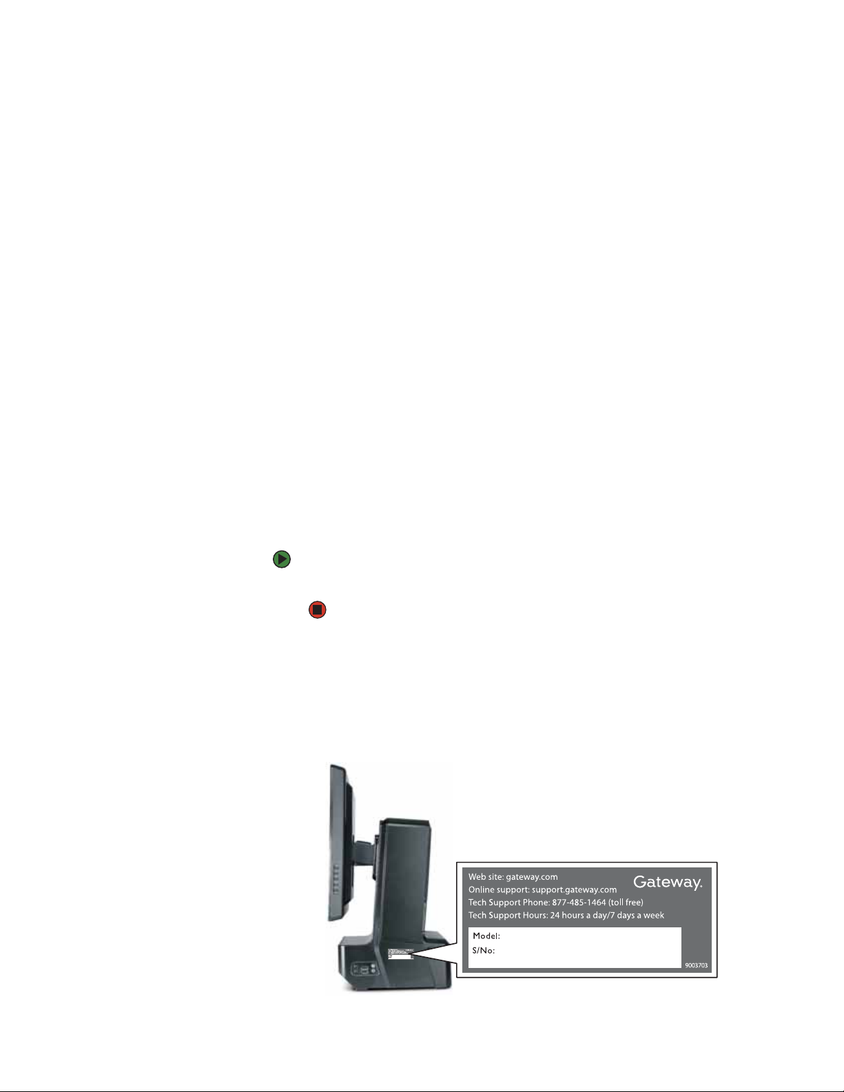
Gateway contact information
The label on the side of your computer case contains information that identifies
your computer model and serial number. Gateway Customer Care will need this
information if you call for assistance.
2
Page 7
www.gateway.com
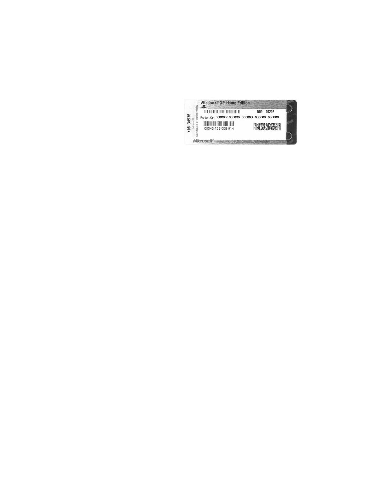
Microsoft Certificate of Authenticity
The Microsoft Certificate of Authenticity label found on the back or side of your
computer includes the product key code for your operating system. If you ever
reinstall Windows from the installation CD or DVD, you will need to enter these
numbers to activate Windows.
Microsoft Certificate of Authenticity
3
Page 8

Chapter 1: About This Reference www.gateway.com
4
Page 9

CHAPTER 2
Hardware Features
•Front
•Back
•Right side
• Side port panel
5
Page 10
Chapter 2: Hardware Features www.gateway.com
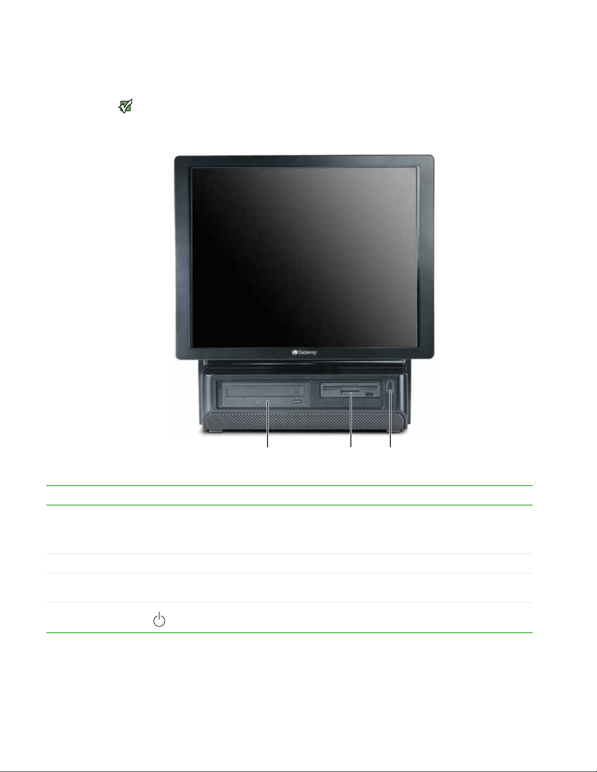
Front
Your computer hardware options and
port locations may vary from the
Important
illustration below.
DVD/CD drive Power button/ power
Component Icon Description
DVD/CD drive Use this drive to listen to audio CDs, install games and programs, watch DVDs, and store large files onto recordable
Diskette drive (optional) Insert a standard 3.5-inch diskette into the optional diskette drive.
Memory card reader
(optional)
Power button and power
indicator
discs (depending on drive type).
This drive may be a CD, recordable CD, DVD, or recordable DVD drive. To identify your drive type and for more
information about your drive, see your user guide.
Insert a memory card from a digital camera, MP3 player, PDA, cellular telephone, or other devices into the memory
card reader.
Press this button to turn the power on or off. You can also configure the power button to operate in Standby/Resum e
mode or Hibernate mode. The power indicator lights when the computer is turned on.
Diskette drive or memory
card reader (optional)
indicator
6
Page 11
www.gateway.com
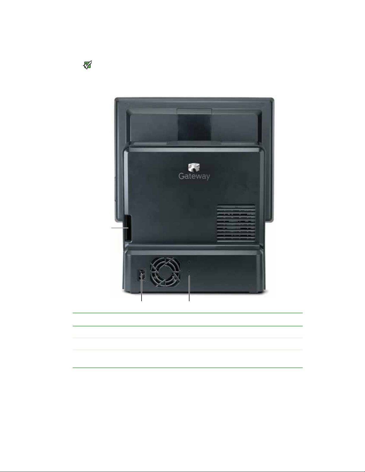
Back
Back
Your computer hardware options and
port locations may vary from the
Important
illustration below.
Opening for cables
Power connector Kensington lock slot
Component Description
Cord exit for port cover Route the cables that are plugged into the side port panel through this opening.
Power connector Plug the power cord into this connector.
Kensington lock slot Attach a cable lock to this slot to prevent unauthorized opening, modification, and theft of
your computer.
7
Page 12

Chapter 2: Hardware Features www.gateway.com
Right side
Monitor controls
Volume control
USB ports
Component Icon Description
Monitor controls Press these buttons to adjust the screen image.
Volume control Press to adjust the volume level of the built-in speakers.
USB ports Plug a USB (Universal Serial Bus) device (such as a USB printer, scanner, camera, keyboard, or mouse) into one of these
ports. For more information, see your user guide.
Headphone jack
Microphone jack
Side port cover
Back panel
release latch (2)
Microphone jack Plug a microphone into this jack. This jack is color-coded red or pink.
Headphone jack Plug powered, analog front speakers, an external amplifier, or headphones into this jack. This jack is color-coded green.
Side port cover Remove this cover to access the ports underneath, such as USB, parallel, serial, IEEE 1394/FireWire™, and audio jacks.
For more information, see “Side port panel” on page 9.
Back panel release latch Slide these latches (one on each side of the computer) toward the back to remove the back panel.
8
Page 13

www.gateway.com
Side port panel
Right side
Your computer hardware options and
port locations may vary from the
Important
illustration below.
Digital (DVI) video in port
Telephone jack (optional)
IEEE 1394/FireWire™
PS/2 mouse port
PS/2 keyboard port
Access the side port panel by removing the port cover on the right side of your
computer.
Modem jack (optional)
(half-height PCI card slot)
4-pin port
Expansion card slots
VGA in port
Parallel port
Serial port
USB ports
S/PDIF jack
IEEE 1394/FireWire™
6-pin (powered) port
Ethernet (network) jack
Center/subwoofer jack
Rear speaker jack
Audio in/side speaker jack
Headphone/front speaker jack
Microphone jack
Component Icon Description
Digital (DVI) video in port If you have a digital video (DVI) expansion card installed, connect its DVI out port to this DVI
in port.
Telephone jack (optional) Plug a telephone into this jack for your desk telephone. The modem cable must be connected
to a wall jack for the telephone to be connected to this jack. For more information on modems,
see your user guide.
®
IEEE 1394/FireWire™ 4-pin
port
(VGA) in port If you have an analog (VGA) video expansion card installed, connect its VGA out port to this
Parallel port Plug a parallel device (such as a printer) into this port. For more information, see your user
Serial port Plug a serial device (such as an older digital camera or mouse) into this port.
Plug IEEE 1394 (also known as Firewire
IEEE 1394 port. For more information on connecting video devices, see your user guide.
VGA in port.
guide.
) devices (such as a digital camcorder) into this 4-pin
9
Page 14

Chapter 2: Hardware Features www.gateway.com
Component Icon Description
USB ports Plug a USB (Universal Serial Bus) device (such as a USB Iomega™ Zip™ drive, printer, scanner,
PS/2 mouse port Plug a PS/2 mouse into this port.
PS/2 keyboard port Plug a Personal System/2
S/PDIF optical audio jack Plug an S/PDIF optical audio connection to this jack.
Microphone jack (pink plug) Plug a microphone into this jack.
Headphone/analog
speakers jack (green plug)
-ORFront speakers jack
Modem jack Plug a modem cable into this jack. For more information on modems, see your user guide.
Expansion card slots Install a PCI card or AGP graphics card into the riser card slots.
IEEE 1394/FireWire™ 6-pin
port
camera, keyboard, or mouse) into one of these ports. For more information, see your user
guide.
®
(PS/2) keyboard into this port.
If the back of your computer has five audio jacks, this jack is user configurable for one of the
following:
Headphone: Plug headphones or amplified speakers into this jack (Default).
Stereo out: Plug your front left and right speakers into this jack.
For information on configuring this jack, see your user guide.
If the back of your computer has three audio jacks, this jack is the headphone/analog speaker
(line out) jack. Plug powered speakers, an external amplifier, or headphones into this jack.
®
Plug IEEE 1394 (also known as Firewire
IEEE 1394 port. For more information on connecting video devices, see your user guide.
) devices (such as a digital camcorder) into this 6-pin
Ethernet (network) jack Plug an Ethernet network cable or a device (such as a DSL or cable modem for a broadband
Center/subwoofer jack
(orange plug)
Rear speaker jack
(black plug) (optional)
Audio input (Line in) jack
(blue plug)
-ORSide speaker jack
Internet connection) into this jack.
Plug your center speaker and subwoofer into this optional jack.
For information on configuring this jack, see your user guide.
Plug your rear right and left speakers into this optional jack.
For information on configuring this jack, see your user guide.
If the back of your computer has five audio jacks, this jack is user configurable for one of the
following:
Stereo in: Plug an external audio input source (such as a stereo) into this jack so you can
record sound on your computer (Default).
Stereo out: Plug your side left and right speakers into this jack.
For information on configuring this jack, see your user guide.
If the back of your computer has three audio jacks, this jack is the audio input (line in) jack.
Plug an external audio input source (such as a stereo) into this jack so you can record sound
on your computer.
10
Page 15

CHAPTER 3
Maintenance Basics
• Preventing static electricity discharge
• Opening the case
• Replacing the processor fan
• Installing memory
• Replacing the power supply
• Replacing the diskette drive
• Replacing the memory card reader
• Replacing the optical drive
• Replacing the hard drive
• Adding an expansion card
• Replacing the BIOS battery
• Replacing the system board
11
Page 16

Chapter 3: Maintenance Basics www.gateway.com
Preventing static electricity discharge
To avoid exposure to dangerous electrical
voltages and moving parts, turn off your
computer and unplug the power cord
and modem and network cables before
opening the case.
Caution
ESD can permanently damage
electrostatic discharge-sensitive
components in your computer. Prevent
ESD damage by following ESD guidelines
every time you open the computer case.
Warning
To prevent risk of electric shock, do not
insert any object in to the vent holes of the
Wa rning
power supply.
The components inside your computer are extremely sensitive to static
electricity, also known as electrostatic discharge (ESD).
Before opening the computer case, follow these guidelines:
■ Turn off your computer.
■ Wear a grounding wrist strap (available at most electronics stores) and
attach it to a bare metal part of your computer.
■ This computer case contains hazardous moving parts. Disconnect the
power cord before opening the rear cover.
■ Personal injury can result from contact with the cooling fan if the power
is not disconnected. Before servicing your computer, make sure that you
first turn off the computer and unplug the power cord.
■ Touch a bare metal surface on the back of the computer.
■ Unplug the power cord and the modem and network cables.
Before working with computer components, follow these guidelines:
■ Avoid static-causing surfaces such as carpeted floors, plastic, and packing
foam.
■ Remove components from their antistatic bags only when you are ready
to use them. Do not lay components on the outside of antistatic bags
because only the inside of the bags provide electrostatic protection.
■ Always hold expansion cards by their edges or their metal mounting
brackets. Avoid touching the edge connectors and components on the
cards. Never slide expansion cards or components over any surface.
Opening the case
To avoid exposure to dangerous electrical
voltages and moving parts, turn off your
computer, then unplug the power cord
and modem cable before opening the
Wa rning
case.
Your computer case provides easy access to internal components.
To remove the back panel:
1 Follow the instructions in “Preventing static electricity discharge” on
page 12.
2 Shut down your computer, then disconnect the power cord and modem,
network, and all peripheral device cables.
3 Place your computer face-down on a clean, soft, dry surface. (Although the
photographs show the computer upright, your computer should be
face-down during servicing to avoid tipping over.)
12
Page 17

www.gateway.com
Opening the case
4 Pull both back panel release latches (one on each side of the case), then
lift the back panel away from the case.
Replacing the back panel
To replace the back panel:
1 Slide the tabs on the top of the panel into the slots in the top of the case.
Slots
2 Swing the lower part of the panel down and against the computer until
it clicks into place.
13
Page 18

Chapter 3: Maintenance Basics www.gateway.com
Replacing the processor fan
You need to remove the processor fan assembly to replace the processor fan
or to access system components that are behind the assembly.
To replace the processor fan:
1 Remove the back panel by following the instructions in “Opening the case”
on page 12.
2 Slide the processor fan assembly’s release lever to the left.
3 Swing the top part of the fan assembly away from the computer.
4 Rotate the fan assembly down until it stops.
5 Unplug the fan’s power cable from the system board.
14
Page 19

www.gateway.com
Installing memory
6 Slide the fan assembly out of the computer.
7 Plug the new fan’s power cable into the system board.
8 Slide the new fan assembly into the computer. Make sure that you line up
the posts on the bottom of the assembly with the guide slots inside the
case.
9 Rotate the fan assembly up until it lays flat against the computer and clicks
into place.
10 Replace the back panel by following the instructions in “Replacing the
back panel” on page 13.
Installing memory
When you upgrade or change the computer memory, make sure that you install
the correct type of memory module for your computer. Your computer uses
DIMM memory.
To install or replace DIMM memory:
1 Remove the back panel by following the instructions in “Opening the case”
on page 12.
2 Remove the processor fan assembly by following the instructions in
“Replacing the processor fan” on page 14.
3 Find the memory module banks on your system board.
4 If you are removing a DIMM from the memory module bank, gently pull
the plastic tabs away from the sides of the memory module and remove it.
- OR -
15
Page 20

Chapter 3: Maintenance Basics www.gateway.com
If you are adding a DIMM to an empty memory module bank, gently pull
the plastic tabs away from the sides of the memory module bank.
5 Align the notches on the new DIMM with the notches on the memory
module bank and press the module firmly into the bank until the module
clicks into place. The tabs on the sides of the memory module should
secure the memory module automatically.
6 Replace the processor fan assembly by following the instructions in
“Replacing the processor fan” on page 14.
7 Replace the back panel by following the instructions in “Replacing the
back panel” on page 13.
8 Return your computer to its upright position.
9 Reconnect the cables and the power cord.
10 Turn on your computer. Windows starts and the Windows desktop
appears.
11 Click Start, Control Panel, then click Performance and Maintenance (if
in Category view). Click/Double-click System. The amount of memory in
your computer is shown at the bottom of the System Properties dialog box
in the General tab.
Replacing the power supply
To replace the power supply:
1 Remove the back panel by following the instructions in “Opening the case”
on page 12.
2 Remove the processor fan assembly by following the instructions in
“Replacing the processor fan” on page 14.
16
Page 21

www.gateway.com
Replacing the power supply
3 Unplug the power supply from the system board.
4 Pull the power supply release lever out (toward you) until the power
supply slides freely, then slide the power supply out of the computer.
5 Slide the new power supply into the power supply bay until it clicks into
place.
6 Plug the new power supply into the system board.
7 Replace the processor fan assembly by following the instructions in
“Replacing the processor fan” on page 14.
8 Replace the back panel by following the instructions in “Replacing the
back panel” on page 13.
17
Page 22

Chapter 3: Maintenance Basics www.gateway.com
Replacing the diskette drive
To replace the diskette (floppy) drive:
1 Remove the back panel by following the instructions in “Opening the case”
on page 12.
2 Remove the power supply by following the instructions in “Replacing the
power supply” on page 16. You do not need to unplug the power supply
from the system board.
3 Pull the diskette drive release latch out (toward you).
4 Slide the diskette drive out (toward you) until it stops, then unplug the
cables from the drive.
18
Page 23

www.gateway.com
5 Return your computer to its upright position, then slide the diskette drive
out the front of the computer.
6 Slide the new drive into the computer from the front until the front of the
drive is flush with the front of the computer, then slide the drive release
lever forward (away from you) to lock the drive into place.
7 Lay the computer face-down, then reconnect the cables to the drive.
8 Replace the power supply by following the instructions in “Replacing the
power supply” on page 16.
9 Replace the back panel by following the instructions in “Replacing the
back panel” on page 13.
Replacing the memory card reader
To replace the memory card reader:
1 Remove the back panel by following the instructions in “Opening the case”
on page 12.
Replacing the memory card reader
2 Remove the power supply by following the instructions in “Replacing the
power supply” on page 16. You do not need to unplug the power supply
from the system board.
3 Pull the card reader release latch out (toward you).
4 Slide the card reader out (toward you) until it stops, then unplug the cable
from the drive.
5 Return your computer to its upright position, then slide the card reader
out the front of the computer.
6 Slide the new card reader into the computer from the front until the front
of the reader is flush with the front of the computer, then slide the card
reader release lever forward (away from you) to lock the card reader into
place.
7 Lay the computer face-down, then reconnect the cable to the card reader.
8 Replace the power supply by following the instructions in “Replacing the
power supply” on page 16.
9 Replace the back panel by following the instructions in “Replacing the
back panel” on page 13.
19
Page 24

Chapter 3: Maintenance Basics www.gateway.com
Replacing the optical drive
To replace the optical drive:
1 Remove the back panel by following the instructions in “Opening the case”
on page 12.
2 Pull the optical drive release latch out (toward you).
3 Unplug the cables from the optical drive.
4 Return your computer to its upright position, then slide the optical drive
out the front of the computer.
5 Slide the new drive into the computer from the front until the front of the
drive is flush with the front of the computer, then slide the drive release
lever forward (away from you) to lock the drive into place.
6 Lay the computer face-down, then reconnect the cables to the drive.
7 Replace the back panel by following the instructions in “Replacing the
back panel” on page 13.
20
Page 25

www.gateway.com
Replacing the hard drive
To replace the hard drive:
1 Remove the back panel by following the instructions in “Opening the case”
on page 12.
2 Unplug the cables from the hard drive.
3 Push the hard drive release lever to the left, then pull the lever out (toward
you) as far as the lever will go. The lever pulls the hard drive out.
Replacing the hard drive
21
Page 26

Chapter 3: Maintenance Basics www.gateway.com
4 Grasp the hard drive itself, then pull it the rest of the way out of your
computer.
5 Make sure the hard drive release lever is still fully extended, then slide the
new hard drive all the way into the hard drive bay by pushing on the hard
drive itself (not the lever). Make sure that you slide the drive in until it is
flush with the edge of the hard drive bay.
22
6 Reconnect the cables to the drive.
7 Replace the back panel by following the instructions in “Replacing the
back panel” on page 13.
8 Reconnect all external cables and the power cord.
9 Turn on your computer.
10 If Windows does not start, install Windows using the operating system CD
that came with your computer, then install the drivers and applications.
Follow any instructions that may be printed on the operating system CD.
Page 27

www.gateway.com
Adding an expansion card
You can install a half-height PCI card, a full-height PCI card, or an AGP video card
in your computer.
To install a half-heght expansion card:
1 Remove the back panel by following the instructions in “Opening the case”
on page 12.
2 Remove the PCI riser card by pulling on its green handle.
Adding an expansion card
Do not touch the contacts on the bottom
part of the expansion card. Touching the
contacts can cause electrostatic damage
Caution
to the card.
3 Slide a half-height PCI card into the half-height PCI slot. You can slightly
seesaw the card end-to-end to help insert the card, but do not bend the
card sideways.
Half-height PCI slot
4 Replace the PCI riser card by sliding it back into place.
5 Replace the back panel by following the instructions in “Replacing the
back panel” on page 13.
23
Page 28

Chapter 3: Maintenance Basics www.gateway.com
To install a full-height expansion card or graphics AGP card:
1 Remove the back panel by following the instructions in “Opening the case”
on page 12.
2 Remove the PCI riser card by pulling on its green handle.
Do not touch the contacts on the bottom
part of the expansion card. Touching the
contacts can cause electrostatic damage
Caution
to the card.
3 Press the two tabs on the card retention lever together, then lift the card
retention lever out of the way.
24
Page 29

www.gateway.com
Adding an expansion card
4 Remove the metal EMI shield next to the slot you are adding a card to. The
PCI card slot is the slot furthest from the riser card handle, and the AGP
graphics card slot is the slot closest to the handle.
5 Slide a PCI card into the PCI slot, or slide an AGP graphics card into the
AGP slot. You can slightly seesaw the card end-to-end to help insert the
card, but do not bend the card sideways.
6 Press the card retention lever down until it clicks into place.
7 Replace the PCI riser card by sliding it back into place.
25
Page 30

Chapter 3: Maintenance Basics www.gateway.com
8 Replace the back panel by following the instructions in “Replacing the
back panel” on page 13.
Replacing the BIOS battery
Danger of explosion if battery is
Replace only with the same or equivalent
type recommended by the manufacturer.
Dispose of used batteries following the
manufacturer’s instructions.
Warning
incorrectly replaced.
If the computer clock does not keep time or the settings in the BIOS Setup utility
are not saved when you turn off your computer, replace the system BIOS battery.
Use a battery of the same size and voltage as the original battery that was in
your computer.
To replace the battery:
1 Restart your computer.
2 During the restart, press and hold the F1 key. The main menu of the
BIOS Setup utility opens.
3 Because changing the BIOS battery will reset the BIOS to factory default
settings, write down the values you may have changed from the factory
settings, then exit from the utility.
4 Remove the back panel by following the instructions in “Opening the case”
on page 12.
5 Remove the processor fan assembly by following the instructions in
“Replacing the processor fan” on page 14.
6 Locate the old battery on the system board and note its orientation. You
will need to install the new battery the same way.
26
Battery
7 Push the battery release tab. The battery pops out of the socket.
8 Make sure that the positive (+) side of the new battery is facing up, then
press the battery into the socket until it snaps into place.
9 Replace the processor fan assembly by following the instructions in
“Replacing the processor fan” on page 14.
Page 31

www.gateway.com
10 Replace the back panel by following the instructions in “Replacing the
back panel” on page 13.
11 Reconnect all external cables and the power cord.
12 Turn on your computer, and press F2 during startup to open the BIOS
Setup utility.
13 In the BIOS Setup utility, restore any settings that you wrote down in
Step 3.
14 Save all your settings and exit the BIOS Setup utility.
Replacing the system board
To replace the system board:
1 Remove the back panel by following the instructions in “Opening the case”
on page 12.
2 Remove the PCI riser card and half-height PCI card (if installed) by
following the instructions in “Adding an expansion card” on page 23.
Replacing the system board
3 Remove the processor fan assembly by following the instructions in
“Replacing the processor fan” on page 14.
4 Loosen the four screws that secure the heat sink to the processor, then
remove the heat sink. The screws are captive screws, so they will not fall
out of the heat sink.
Heat sink screws
Heat sink screws
5 Disconnect the power and data cables from the system board, noting their
locations and orientation. (You will reconnect the cables after you install
the new board.) You can also mark the cables with tape labels to simplify
reconnecting cables later.
27
Page 32

Chapter 3: Maintenance Basics www.gateway.com
6 Remove the seven screws that secure the system board to the case.
Screws
Screws
7 Slide the system board to the right until it slides free from the case, then
remove it completely from the case.
8 Slide the new system board into place, then replace the seven screws you
removed previously.
9 Replace the heat sink and tighten the four captive screws.
10 Replace the processor fan assembly by following the instructions in
“Replacing the processor fan” on page 14.
11 Replace the half-height PCI card and the PCI riser card by following the
instructions in “Adding an expansion card” on page 23.
12 Replace the back panel by following the instructions in “Replacing the
back panel” on page 13.
28
Page 33

Page 34

MAN PFL6 HW REF R0 3/06
 Loading...