

Page 1

Gateway Profile
™
service guide
5
Customizing
Troubleshooting
Page 2

Page 3

Contents
Replacing Components in Your Gateway Profile 5
About this guide . . . . . . . . . . . . . . . . . . . . . . . . . . . . . . . . . . . . . . . . . . . . . . . . . . . . . 1
Preparing your work space . . . . . . . . . . . . . . . . . . . . . . . . . . . . . . . . . . . . . . . . . . . . 2
Preventing static electricity discharge . . . . . . . . . . . . . . . . . . . . . . . . . . . . . . . . 3
Preparing your computer . . . . . . . . . . . . . . . . . . . . . . . . . . . . . . . . . . . . . . . . . . 4
Replacing the front panel and speaker grille . . . . . . . . . . . . . . . . . . . . . . . . . . . . . . 5
Replacing the back panel . . . . . . . . . . . . . . . . . . . . . . . . . . . . . . . . . . . . . . . . . . . . . 8
Replacing the I/O panel . . . . . . . . . . . . . . . . . . . . . . . . . . . . . . . . . . . . . . . . . . . . . . 10
Replacing the blower assembly . . . . . . . . . . . . . . . . . . . . . . . . . . . . . . . . . . . . . . . 14
Replacing drives . . . . . . . . . . . . . . . . . . . . . . . . . . . . . . . . . . . . . . . . . . . . . . . . . . . 16
Replacing the optical drive . . . . . . . . . . . . . . . . . . . . . . . . . . . . . . . . . . . . . . . . 16
Replacing the diskette drive . . . . . . . . . . . . . . . . . . . . . . . . . . . . . . . . . . . . . . . 18
Replacing the hard drive . . . . . . . . . . . . . . . . . . . . . . . . . . . . . . . . . . . . . . . . . . 22
Replacing memory modules . . . . . . . . . . . . . . . . . . . . . . . . . . . . . . . . . . . . . . . . . . 26
Replacing the processor . . . . . . . . . . . . . . . . . . . . . . . . . . . . . . . . . . . . . . . . . . . . . 28
Replacing the video board . . . . . . . . . . . . . . . . . . . . . . . . . . . . . . . . . . . . . . . . . . . 33
Replacing the Mini PCI card . . . . . . . . . . . . . . . . . . . . . . . . . . . . . . . . . . . . . . . . . . 35
Replacing the speakers . . . . . . . . . . . . . . . . . . . . . . . . . . . . . . . . . . . . . . . . . . . . . . 38
Replacing the LCD panel assembly . . . . . . . . . . . . . . . . . . . . . . . . . . . . . . . . . . . . 42
Replacing the CMOS battery . . . . . . . . . . . . . . . . . . . . . . . . . . . . . . . . . . . . . . . . . 49
Replacing the system board . . . . . . . . . . . . . . . . . . . . . . . . . . . . . . . . . . . . . . . . . . 51
i
Page 4

ii
Page 5

Replacing
Components in
Your Gateway
Profile 5
About this guide
Use this service guide to help plan your maintenance tasks
for the Gateway Profile 5. All tasks covered in this guide can
be performed by a field technician without jeopardizing
your computer’s warranty.
For information on your computer’s general maintenance,
technical support, safety notices, and regulatory notices,
see your Gateway user’s guide.
If you have suggestions regarding the content of this guide,
send an e-mail with the subject “Service Guide Comments”
to channel.services@gateway.com
.
© 2003 Gateway, Inc. All rights reserved. Gateway, Gateway Countr y, the Gateway
stylized logo, and the black-and-white spot design are trademarks or registered
trademarks of Gateway, Inc. in the United States a nd other countries. All other brands
and product names are trademarks or registered trademarks of their respective
companies.
1
Page 6

Please check out our eBay auctions for more great
deals on Factory Service Manuals:
Page 7

Replacing Components i n Your Gateway Profile 5
Preparing your w ork space
Before performing maintenance on your computer, make sure that your work
space and your computer are correctly prepared.
■ Wear a grounding (ESD) wrist strap.
■ Use a grounded or dissipative work mat.
■ Use a stable and strong table.
■ Make sure that the table top is large enough to hold each component as
you remove it.
■ Use bright lighting to make part identification easier.
■ Keep your work surface free from clutter and dust that may damage
components.
■ Use a magnetized screwdriver for removing screws.
■ As you remove components and screws, lay them toward the back of your
work surface (behind your computer) or far enough to the side that your
arms do not accidentally brush components or screws onto the floor.
■ To help keep track of screws, try the following:
■ Place each component’s screws in their own section of a parts sorter.
■ Place each component’s screws next to the component on your work
surface.
■ When you place flat-headed screws on your work surface, stand them
on their heads to prevent the screws from rolling off the table.
2
www.gateway.com
Page 8

Preparing your wor k space
Preventing static electricity discharge
The components inside your computer are extremely sensitive to static
electricity, also known as electrostatic discharge (ESD).
Warning ESD can permanently damage electrostatic
discharge-sensitiv e components in y our computer . Prev ent
ESD damage by following ESD guidelines every time you
open the computer case.
Warning To avoid exposure to dangerous electrical voltages and
moving parts, turn off your c omputer and unplu g the power
cord before opening the case.
Before opening the computer case, follow these guidelines:
■ Turn off the computer power.
■ Wear a grounding wrist strap (available at most electronics stores) and
attach it to a bare metal part of your workbench or other grounded
connection.
Warning To p revent risk of el ectr ic sho ck, do n ot inse r t any ob ject
into the vent holes of the power supply.
■ Touch a bare metal surface on your workbench or other grounded object.
■ Unplug the power cord and network cables.
Before working with computer components, follow these guidelines:
■ Avoid static-causing surfaces such as carpeted floors, plastic, and packing
foam.
■ Remove components from their antistatic bags only when you are ready
to use them. Do not lay components on the outside of antistatic bags
because only the inside of the bags provide electrostatic protection.
■ Avoid touching the edge connectors and components on the Mini-PCI
cards. Never slide Mini-PCI cards or components over any surface.
www.gateway.com
3
Page 9

Replacing Components i n Your Gateway Profile 5
Preparing your co mputer
Warning To avoid exposure to dangerous electrical voltages and
moving parts, turn off your computer, then unplug the
power cord before opening the case.
To prepare your computer:
1 Turn off your computer.
2 Following all static electricity discharge precautions, disconnect the power
cord and all other external cables.
3 Press the power button to drain any residual power from your computer.
4
www.gateway.com
Page 10
Replacing the front panel and speaker grille
Replacing the front panel and
speaker grille
Time to complete: 1.5 minutes
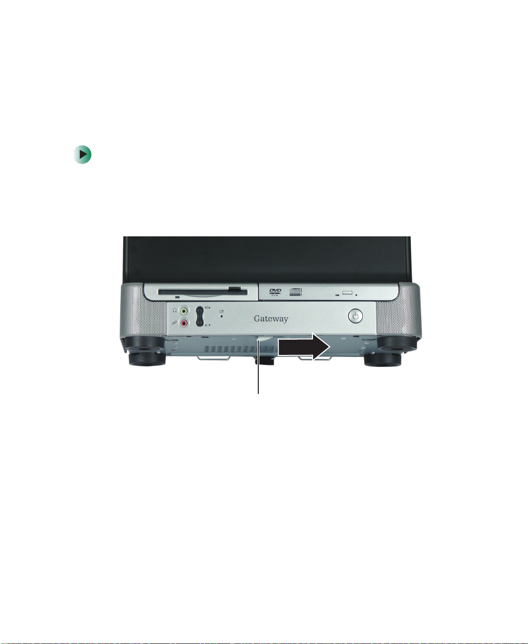
To replace the front panel and s peaker grille:
1 Turn off the computer and prepare it by following the instructions in
“Preparing your computer” on page 4.
2 Tilt the computer back slightly, then slide the front panel release latch to
the right. The panel detaches from the computer.
Front panel
release latch
- OR -
Slide a pen, pencil, or screwdriver between the computer and the tabletop,
then slide the tool to the right. The panel detaches from the computer.
www.gateway.com
5
Page 11
Replacing Components i n Your Gateway Profile 5
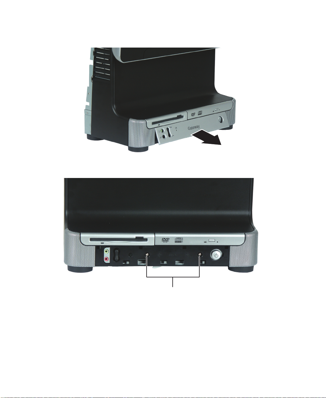
3 Remove the front panel from the computer.
4 Remove the two screws that secure the speaker grille panel to the computer.
Screws
6
www.gateway.com
Page 12
Replacing the front panel and speaker grille
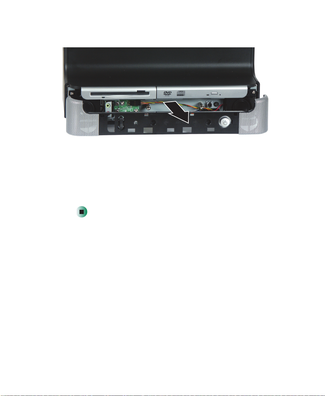
5 Pull the speaker grille off the computer.
6 Position the new speaker grille panel on the front of the computer, then
press it against the computer until it clicks into place.
7 Position the new front panel between the speakers, then insert the hooks
on the top of the front panel into slots just below the diskette and optical
drives.
8 Press the front panel against the computer until it clicks into place.
www.gateway.com
7
Page 13
Replacing Components i n Your Gateway Profile 5
Replacing the back panel
Time to complete: 2 min utes
Warning To avoid exposure to dangerous electrical voltages and
moving parts, turn off your computer, then unplug the
power cord and modem cable before opening the case.
Tips & Tricks For more stability, place your computer face down to
perform this procedure. Avoid scratching the computer
display by placing it on a towel or other non-abrasive
surface.
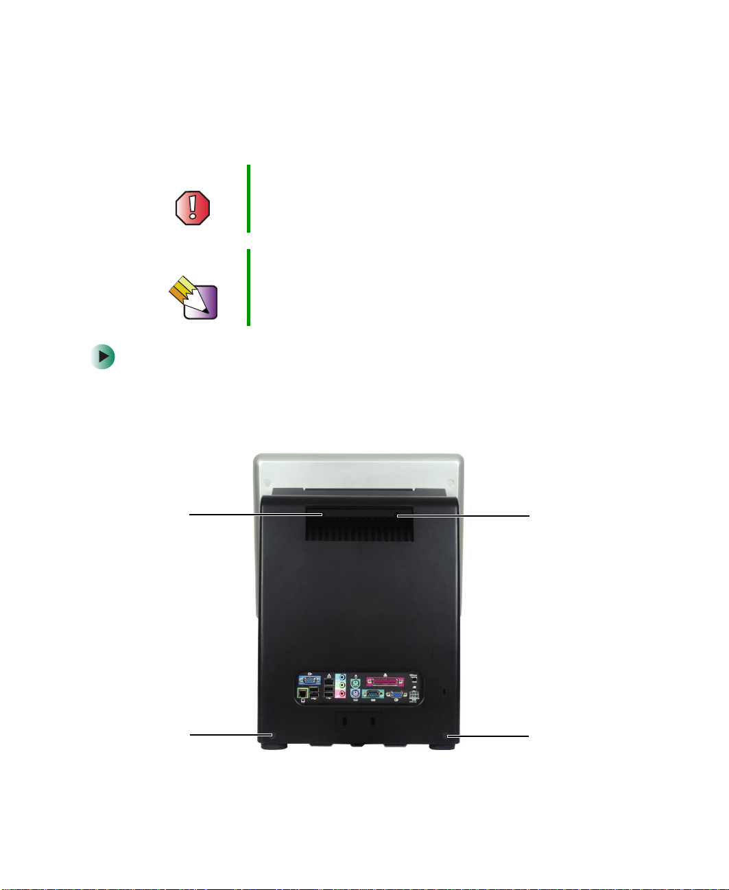
To replace the back panel:
1 Turn off the computer and prepare it by following the instructions in
“Preparing your computer” on page 4.
2 Remove the four screws on the back of the computer case.
Screw
Screw
8
www.gateway.com
Screw
Screw
Page 14
Replacing the back pa nel
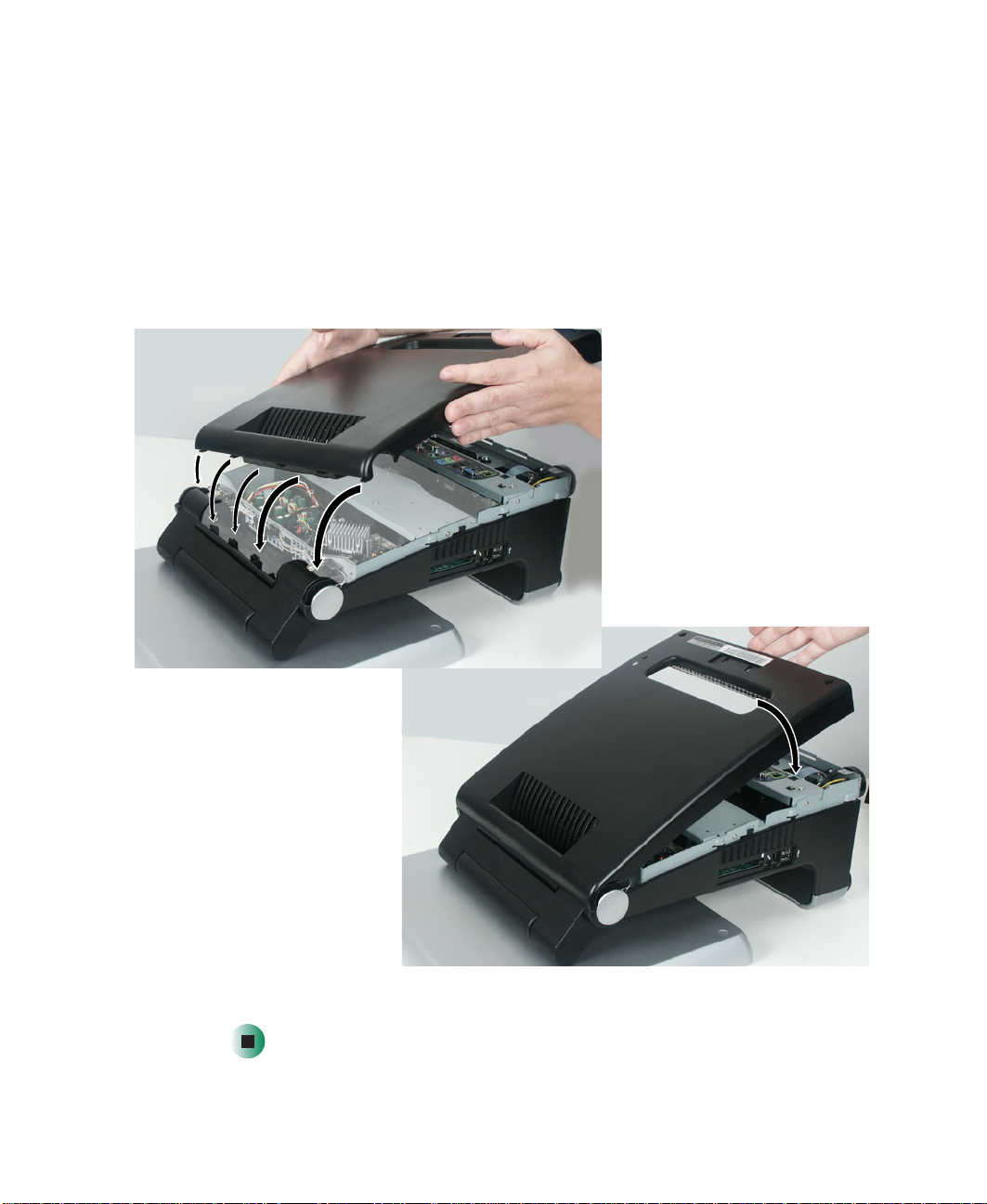
3 With your hands positioned on each side of the case, swing the back panel
up and away from the case and set the panel aside.
4 Make sure that all of the internal cables are arranged inside the case so
they will not be pinched when you close the case.
5 Hook the new back panel’s tabs into the notches on the top of the open
computer’s back, then swing the back panel down and press it into place.
The cover should easily press back into place. If it does not, make sure that
the tabs are aligned with the notches on the computer’s back and try again.
6 Replace the four screws you removed previously.
www.gateway.com
9
Page 15
Replacing Components i n Your Gateway Profile 5
Replacing the I/O panel
Time to complete: 3.5 minutes, 5.5 minutes if panel has V GA out cable
To replace the I/O panel:
1 Turn off the computer and prepare it by following the instructions in
“Preparing your computer” on page 4.
2 Remove back panel by following the instructions in “Replacing the back
panel” on page 8.
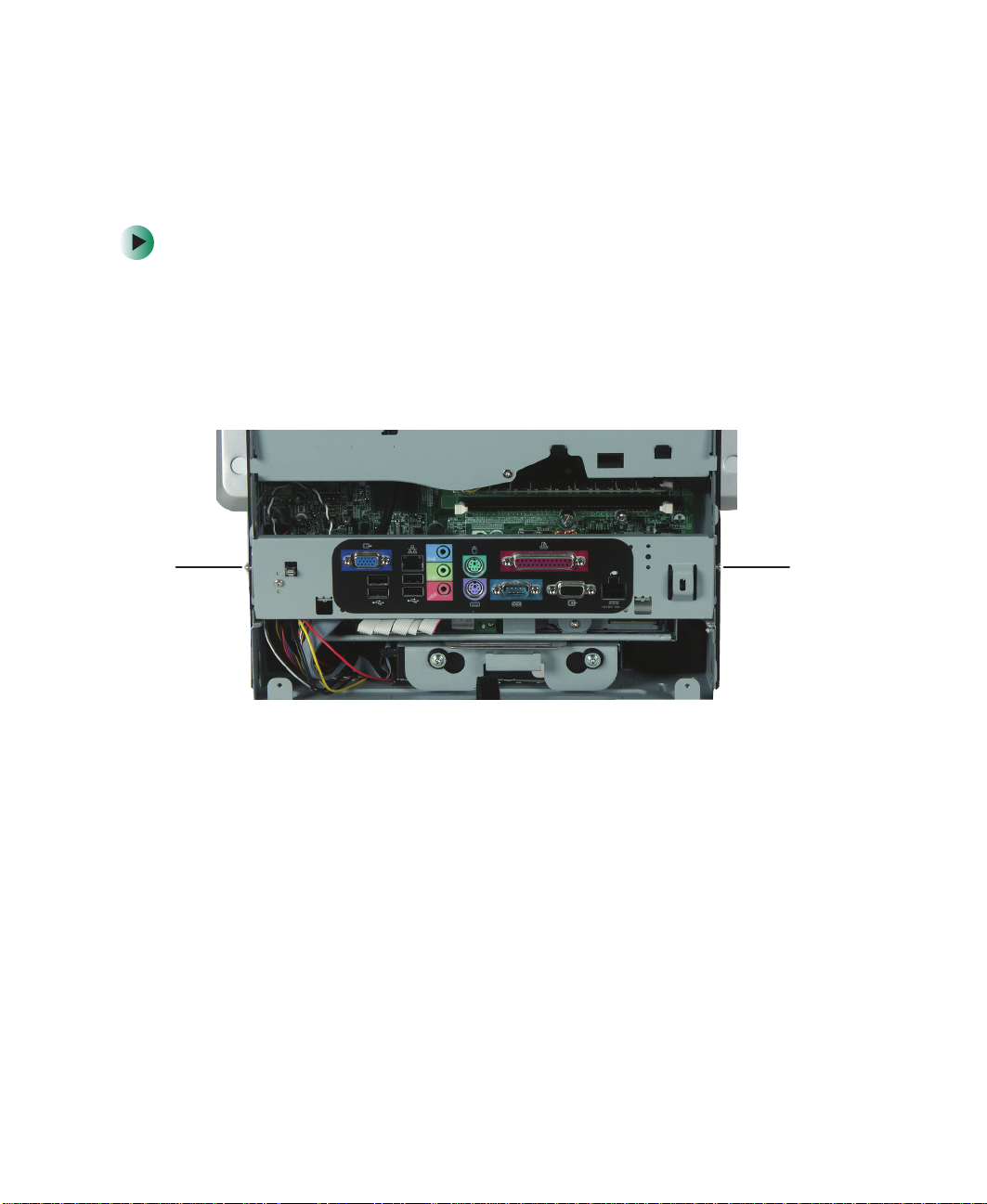
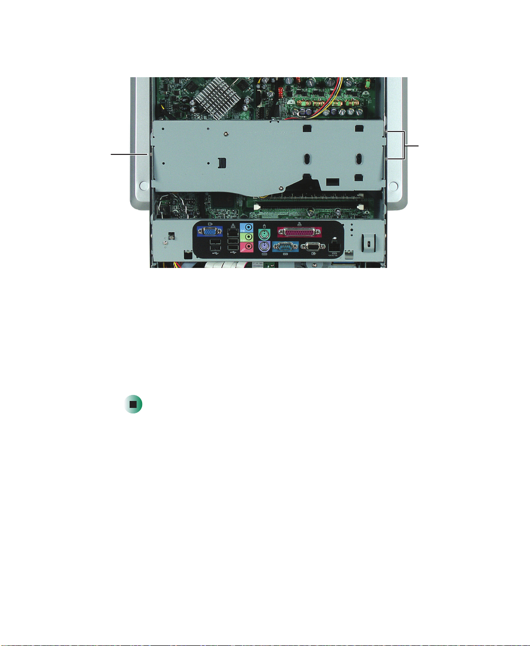
3 Remove the two screws that secure the I/O panel to the computer.
ScrewScrew
10
www.gateway.com
Page 16
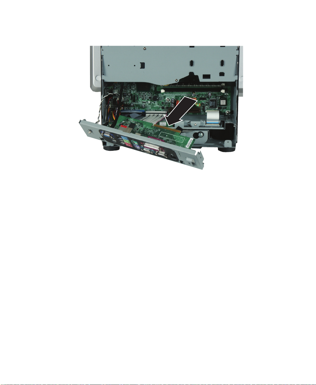
4 Firmly pull the I/O panel away from the computer.
Replacing the I/O panel
www.gateway.com
11
Page 17
Replacing Components i n Your Gateway Profile 5
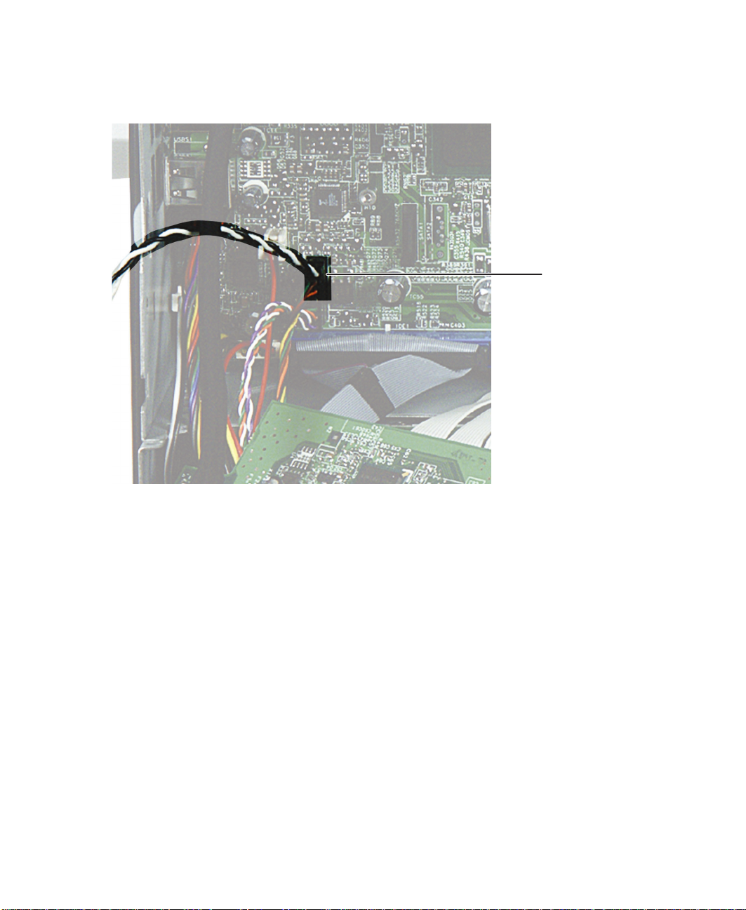
5 Unplug the intrusion switch cable and other cables that connect the I/O
panel to the computer.
Intrusion
switch cable
12
If your computer has a VGA out port on the I/O panel, to disconnect the
VGA out cable you must remove the blower assembly. For more
information, see “Replacing the blower assembly” on page 14.
If your computer has a modem port, unplug the internal modem cable
from the system board.
6 Plug the cables you have unplugged into the new I/O panel. If your
computer has a VGA out port on the I/O panel, plug the VGA out cable
into the system board.
7 If you removed the blower assembly in Step 5, reinstall it by following the
instructions in “Replacing the blower assembly” on page 14.
www.gateway.com
Page 18

Replacing the I/O panel
8 Secure the I/O panel to the computer using the screws you removed
previously.
9 Install the back panel onto the computer by following the instructions in
“Replacing the back panel” on page 8.
www.gateway.com
13
Page 19

Replacing Components i n Your Gateway Profile 5
Blower assembly
Replacing the blower assemb ly
Time to complete: 4 min utes
To replace the blower ass embly:
1 Turn off the computer and prepare it by following the instructions in
“Preparing your computer” on page 4.
2 Remove the back panel of the computer by following the instructions in
“Replacing the back panel” on page 8.
3 Unplug the blower assembly power cable from the system board.
power cable
14
www.gateway.com
Page 20
Replacing the blower ass embly
4 Remove the three screws that secure the blower assembly to the computer.
Screw
5 Pull the blower assembly straight out from the computer.
6 Slide the new blower assembly into place. Make sure the blower assembly’s
power cable is not pinched between the blower assembly and the
processor’s heat sink.
7 Plug the blower assembly power cable into the system board.
8 Reinstall the back panel of the computer by following the instructions in
“Replacing the back panel” on page 8.
Screws
www.gateway.com
15
Page 21
Replacing Components i n Your Gateway Profile 5
Replacing drives
Replacing the optical drive
Time to complete: 4.5 minutes
To replace the optical drive:
1 Turn off the computer and prepare it by following the instructions in
“Preparing your computer” on page 4.
2 Remove the back panel by following the instructions in “Replacing the
back panel” on page 8.
3 Remove the I/O panel by following the instructions in “Replacing the I/O
panel” on page 10.
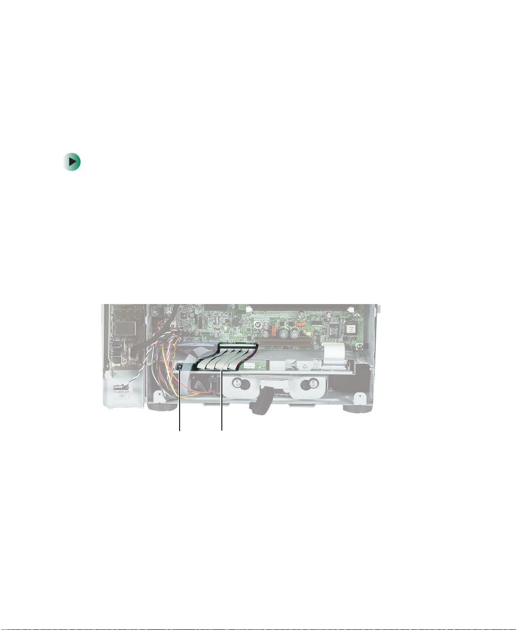
4 Unplug the ribbon cable from the optical drive, then remove the screw
that secures the optical drive to the chassis.
16
Screw Optical drive
ribbon cable
www.gateway.com
Page 22

5 Push the drive out of its bay toward the front of the computer.
Replacing drives
6 From the front of the computer, pull the drive out of the computer.
7 Slide the new drive into the drive slot until the front of the drive is flush
with the front panel of the computer.
8 Secure the drive to the chassis using the screw you removed previously.
9 Plug the drive’s ribbon cable into the new drive.
www.gateway.com
17
Page 23

Replacing Components i n Your Gateway Profile 5
10 Reinstall the I/O panel by following the instructions in “Replacing the I/O
panel” on page 10.
11 Reinstall the back panel by following the instructions in “Replacing the
back panel” on page 8.
Replacing the diskette drive
Time to complete: 4.5 minutes
To replace the diskette drive:
1 Turn off the computer and prepare it by following the instructions in
“Preparing your computer” on page 4.
2 Remove the back panel by following the instructions in “Replacing the
back panel” on page 8.
3 Remove the I/O panel by following the instructions in “Replacing the I/O
panel” on page 10.
18
www.gateway.com
Page 24

Replacing drives
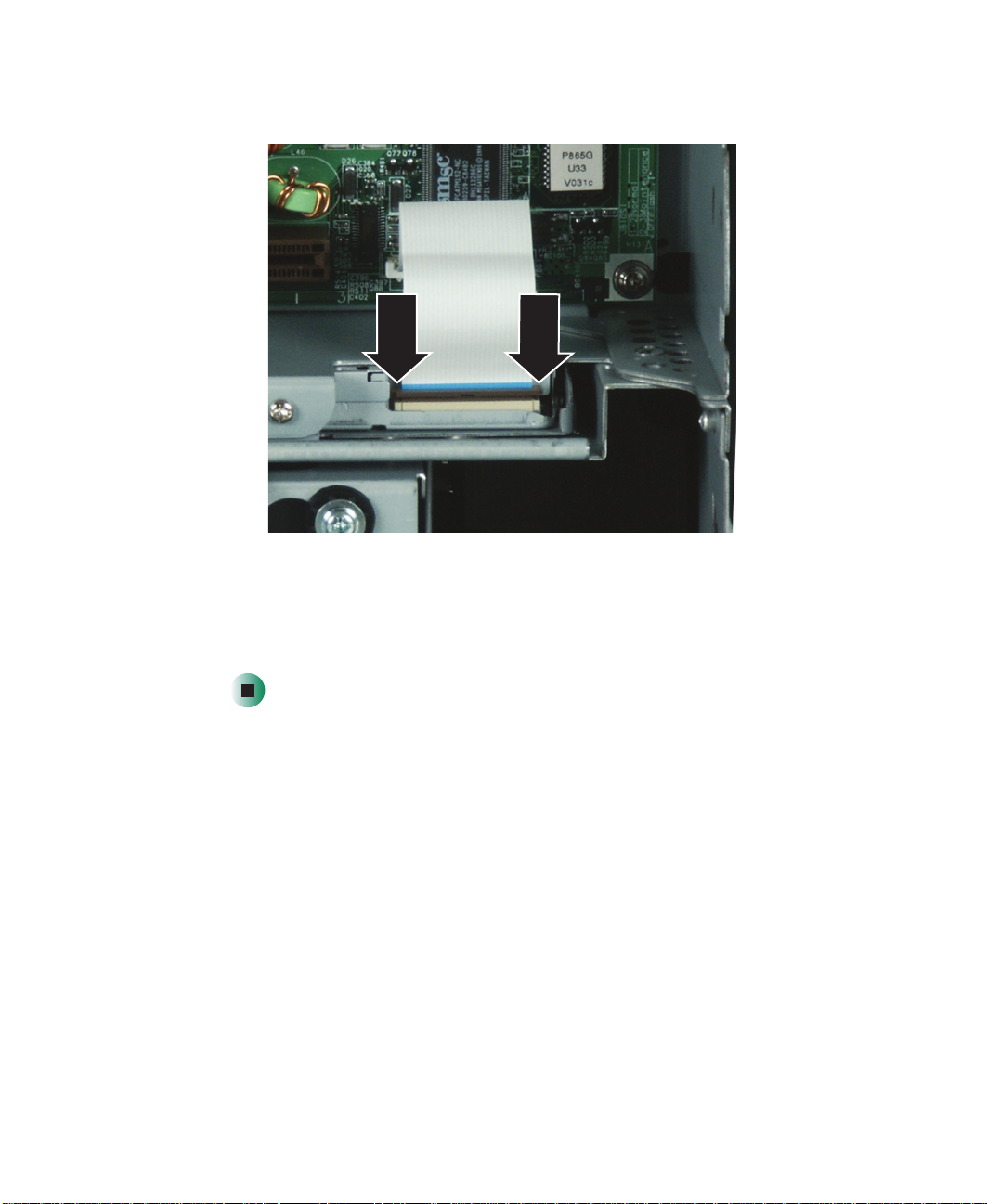
4 Slide the brown locking clip up on the ribbon cable connector, then slide
the ribbon cable out of the connector.
Screw Diskette dr ive
ribbon cable
5 Remove the screw that secures the diskette drive to the chassis.
www.gateway.com
19
Page 25

Replacing Components i n Your Gateway Profile 5
6 Push the drive out of its bay toward the front of the computer.
7 From the front of the computer, pull the drive out of the computer.
8 Slide the new drive into the drive slot until the front of the drive is flush
with the front panel of the computer.
9 Secure the drive to the chassis using the screw you removed previously.
10 Make sure that the drive connector’s brown locking clip is up, then slide
the drive’s ribbon cable into the connector.
20
www.gateway.com
Page 26
Replacing drives
11 Lock the ribbon cable into place by sliding the brown locking clip down.
12 Reinstall the I/O panel by following the instructions in “Replacing the I/O
panel” on page 10.
13 Reinstall the back panel by following the instructions in “Replacing the
back panel” on page 8.
www.gateway.com
21
Page 27

Replacing Components i n Your Gateway Profile 5
Replacing the hard drive
Time to complete: 5 min utes
Tips & Tricks For more stability, place your computer face down to
perform this procedure. Avoid scratching the computer
display by placing it on a towel or other non-abrasive
surface.
To replace the hard drive:
1 Turn off the computer and prepare it by following the instructions in
“Preparing your computer” on page 4.
2 Remove the back panel of the computer by following the instructions in
“Replacing the back panel” on page 8.
3 Press the drive cage release latch.
22
www.gateway.com
Page 28

Replacing drives
4 While holding the latch, pull the drive cage out of the computer.
5 Disconnect the drive cable and power cable from the hard drive.
www.gateway.com
23
Page 29

Replacing Components i n Your Gateway Profile 5
S
Screw
6 Remove the four screws that secure the hard drive to the hard drive cage.
crew
Screw
Screw
24
www.gateway.com
Page 30
Replacing drives
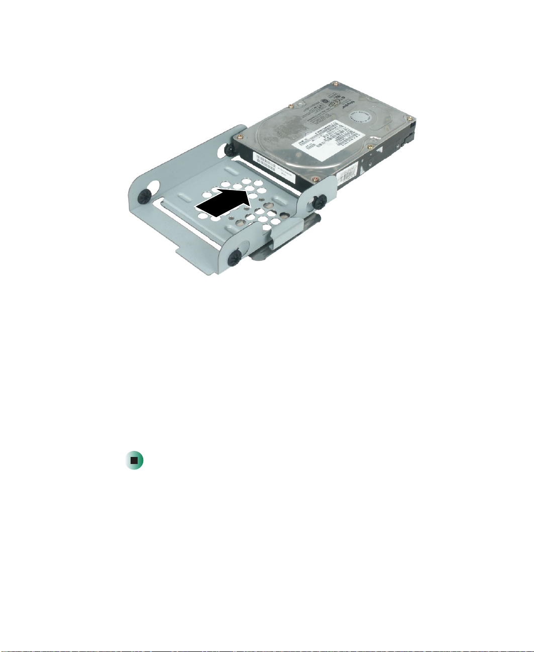
7 Remove the drive.
8 Make sure that the jumpers on the new drive are set the same as the drive
you are replacing.
9 Insert the new drive into the drive cage and secure it with the four screws
removed earlier.
10 Connect the drive cable and power cable to the drive.
11 Slide the drive cage into the computer until it clicks into place. Make sure
that the drive cage’s rails engage the rail guides in the top of the hard drive
cage bay.
12 Reinstall the back panel by following the instructions in “Replacing the
back panel” on page 8.
www.gateway.com
25
Page 31
Replacing Components i n Your Gateway Profile 5
Memory mo dules
Replacing memory modules
Time to complete: 4.5 minutes
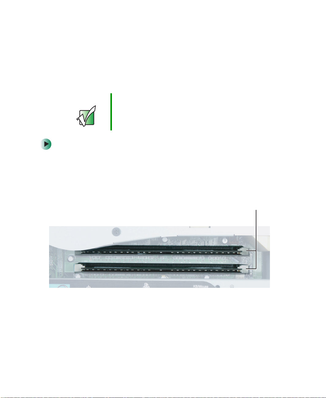
When you upgrade your computer memory, make sure that you install the
correct type of memory module for your computer. Your computer uses DIMM
memory.
Important Use only DDR266, DDR333, or DDR400 DIMM memory
modules. Maximum me mory ca pacity is 2 GB.
To replace memor y modules:
1 Turn off the computer and prepare it by following the instructions in
“Preparing your computer” on page 4.
2 Remove the back panel of the computer by following the instructions in
“Replacing the back panel” on page 8. The memory module banks are
located between the I/O ports and the blower assembly.
26
www.gateway.com
Page 32

Replacing memory modul es
3 If you are removing a memory module from the memory module bank,
gently pull the plastic tabs away from the sides of the memory module
and remove it.
- OR -
If you are adding a memory module to an empty memory module bank,
gently pull the plastic tabs away from the sides of the memory module
bank.
4 Align the notch on the new memory module with the notch on the
memory module bank and press firmly into the bank. The tabs on the sides
of the memory module should secure the memory module automatically.
5 Reinstall the back panel by following the instructions in “Replacing the
back panel” on page 8.
www.gateway.com
27
Page 33

Replacing Components i n Your Gateway Profile 5
Replacing the processor
Time to complete: 5 min utes
Tips & Tricks For more stability, place your computer face down to
perform this procedure. Avoid scratching the computer
display by placing it on a towel or other non-abrasive
surface.
To replace the processor:
1 Turn off the computer and prepare it by following the instructions in
“Preparing your computer” on page 4.
2 Remove the back panel of the computer by following the instructions in
“Replacing the back panel” on page 8.
3 Remove the blower assembly by following the instructions in “Replacing
the blower assembly” on page 14.
28
www.gateway.com
Page 34
Replacing the process or
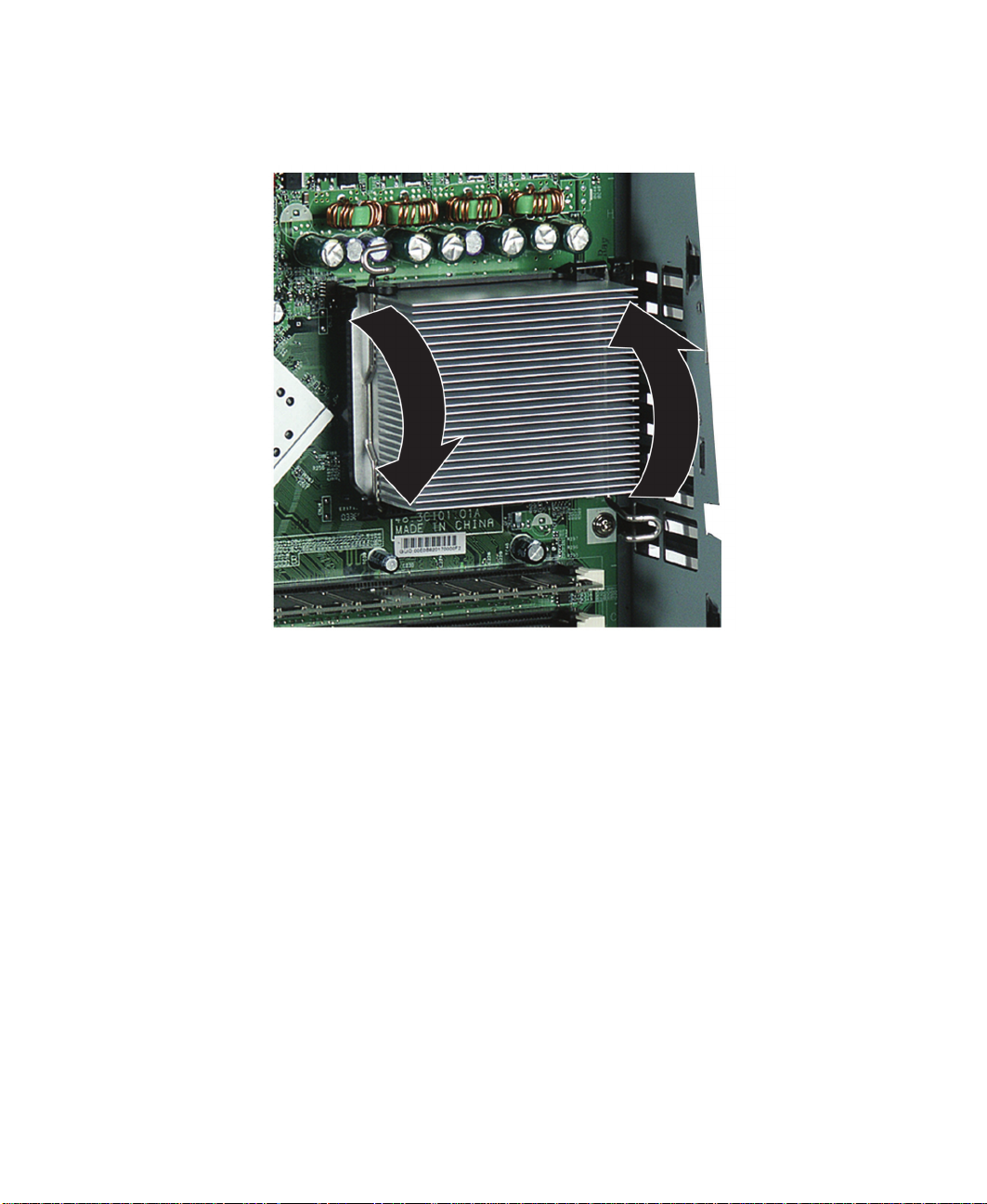
4 Press each heat sink retention clip toward the system board and away from
the heat sink, then rotate each clip out of the way.
www.gateway.com
29
Page 35

Replacing Components i n Your Gateway Profile 5
5 Gently move the heat sink side to si de to loosen it from the processor, then
lift the heat sink away from the processor.
30
www.gateway.com
Page 36
Replacing the process or
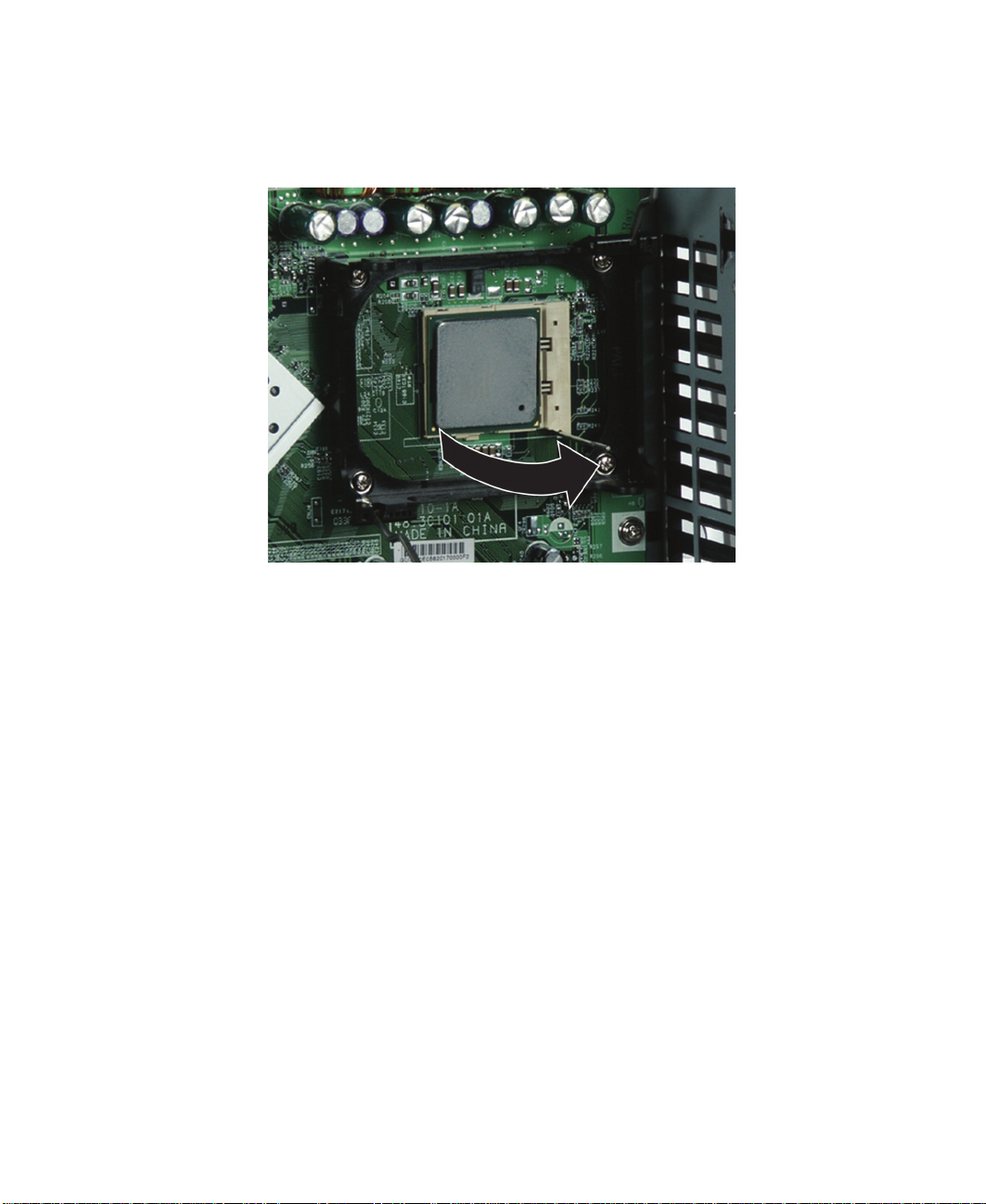
6 While holding your hand under the processor in case the processor falls
out of the socket, rotate the processor release lever to the fully open
position (90°).
7 Lift the processor out of the socket.
8 Before inserting the processor into the socket, make sure that:
■ The processor release lever is open all the way (90° from the closed
position).
■ The triangular arrows on the corner of the processor align with the
triangular icon on the lower-right corner of the processor socket.
9 Install the new processor into the processor socket, then press the processor
locking lever down until it clicks into place.
10 Apply thermal grease to the top of the processor or the bottom of the heat
sink, if necessary. Heat sinks from Gateway have thermal grease already
applied.
11 Place the heat sink onto the processor, then press the heat sink retaining
clips down until they click into place.
www.gateway.com
31
Page 37

Replacing Components i n Your Gateway Profile 5
12 Reinstall the blower assembly by following the instructions in “Replacing
the blower assembly” on page 14.
13 Reinstall the back panel by following the instructions in “Replacing the
back panel” on page 8.
32
www.gateway.com
Page 38
Replacing the video boa rd
Replacing the video board
Time to complete: 5.5 minutes
Depending on your configuration, your computer may not have a video board
installed.
To replace the video boar d:
1 Turn off the computer and prepare it by following the instructions in
“Preparing your computer” on page 4.
2 Remove the back panel by following the instructions in “Replacing the
back panel” on page 8.
3 Remove the blower assembly by following the instructions in “Replacing
the blower assembly” on page 14.
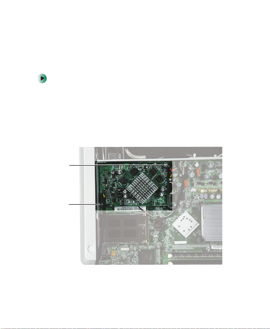
4 Remove the two screws that secure the video board to the computer.
Screw
Screw
5 Pry under the lower-right corner of the board to pull it loose, then pull
the entire video board away from the computer.
www.gateway.com
33
Page 39

Replacing Components i n Your Gateway Profile 5
6 Carefully line up the new video board’s screw holes with the mounting
posts on the system board, then press the video board into place.
Warning Make sure the Mini PCI card’ s antenna cab les do not block
the video board connector.
7 Secure the video board to the system board with the two screws you
removed previously.
8 Reinstall the blower assembly by following the instructions in “Replacing
the blower assembly” on page 14.
9 Reinstall the back panel by following the instructions in “Replacing the
back panel” on page 8.
34
www.gateway.com
Page 40

Replacing the Mini PC I card
Replacing the Mini PCI car d
Time to complete: 6 minutes
Caution By law, only approved wireless modules prov ided by
Gateway or by an authorized Gateway representative
explicitly for the Gateway Profile 5 may be installed in this
computer.
To replace the Mini PCI card:
1 Turn off the computer and prepare it by following the instructions in
“Preparing your computer” on page 4.
2 Remove the back panel by following the instructions in “Replacing the
back panel” on page 8.
3 Remove the blower assembly by following the instructions in “Replacing
the blower assembly” on page 14.
4 If your computer has a video board covering the Mini PCI slot, remove the
video board by following the instructions in “Replacing the video board”
on page 33.
5 Unplug the two antenna cables from the Mini PCI card.
MAIN
(black) cable
AUX
(gray) cable
www.gateway.com
35
Page 41

Replacing Components i n Your Gateway Profile 5
6 Press outward on the two Mini PCI retaining clips until the card flips up.
7 Remove the Mini PCI card from the slot.
36
8 Insert the new Mini PCI card into the slot, then press it down until the
retaining clips snap into place. The card must be fully seated in the slot
before the retaining clips will snap into place.
www.gateway.com
Page 42

Replacing the Mini PC I card
9 Plug the antenna cables back into the Mini PCI card. The gray cable
connects to the post labeled
labeled
AUX.
MAIN, and the black cable connects to the post
10 If you removed a video board, reinstall it by following the instructions in
“Replacing the video board” on page 33.
11 Reinstall the blower assembly by following the instructions in “Replacing
the blower assembly” on page 14.
12 Reinstall the back panel by following the instructions in “Replacing the
back panel” on page 8.
www.gateway.com
37
Page 43

Replacing Components i n Your Gateway Profile 5
(
Replacing the speakers
Time to complete: 9 min utes
To replace the speakers:
1 Turn off the computer and prepare it by following the instructions in
“Preparing your computer” on page 4.
2 Remove the back panel by following the instructions in “Replacing the
back panel” on page 8.
3 Remove the I/O panel by following the instructions in “Replacing the I/O
panel” on page 10.
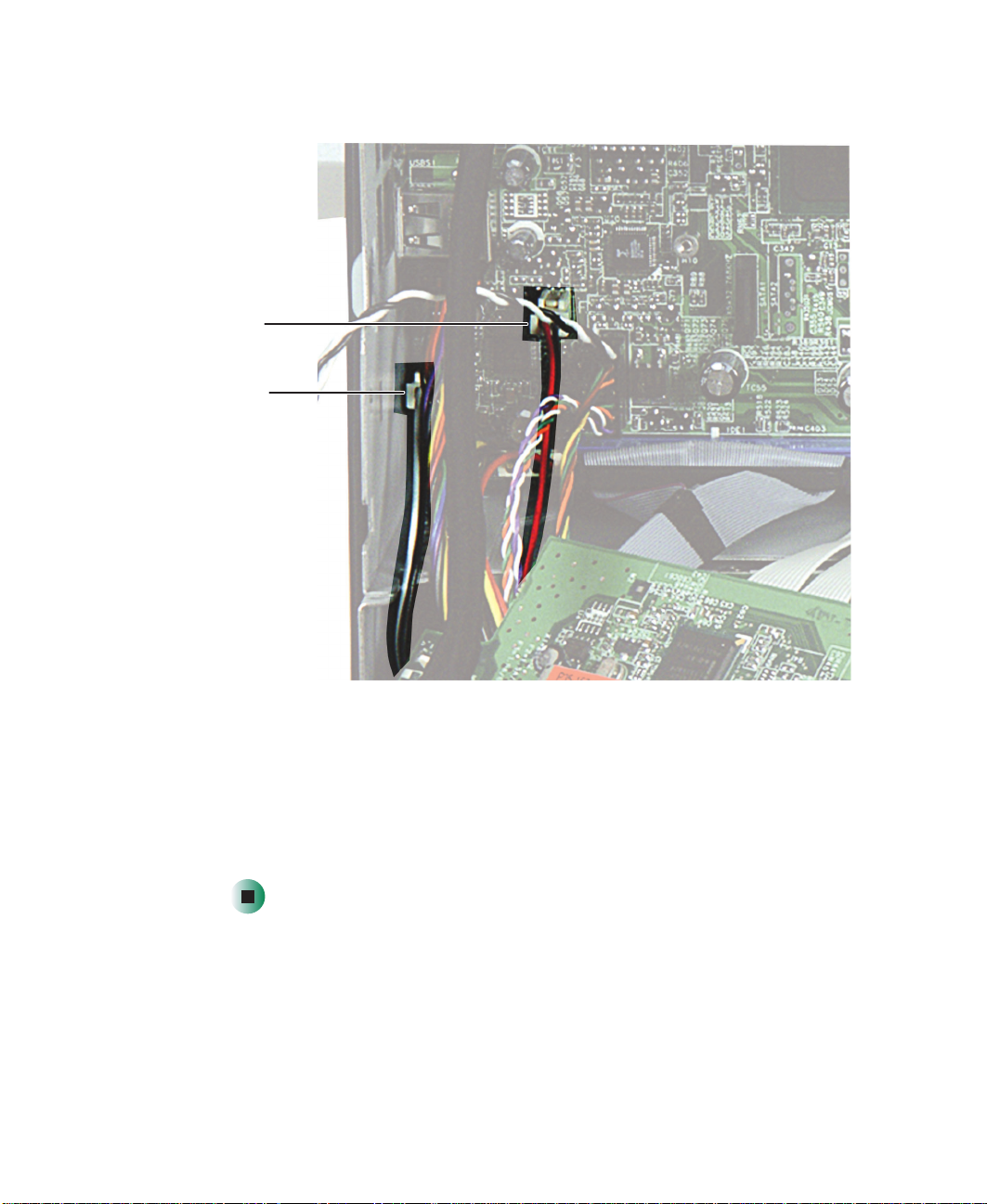
4 Unplug the speaker wires from the system board.
speaker wire
(red and black)
speaker wire
white and black)
38
Right
Left
www.gateway.com
Page 44

Replacing the speaker s
5 Remove the front panel and speaker grille by following the instructions
in “Replacing the front panel and speaker grille” on page 5.
6 Remove the two screws that secure the front control circuit board to the
computer.
Screws
7 Pull the front control circuit board away from the computer to expose the
left speaker wires that run underneath it.
www.gateway.com
39
Page 45

Replacing Components i n Your Gateway Profile 5
8 Remove the two screws from the speaker you are replacing.
Screws
9 Pull the speaker out of the computer while carefully threading the speaker
wire out of the wire access port.
Wire access port
10 Insert the replacement speaker into the computer, then secure it using the
two screws you removed previously.
11 Thread the speaker wire along the inside of the front panel area, then
thread the speaker wire connector through the wire access port.
40
www.gateway.com
Page 46
Replacing the speaker s
12 Plug the wire into the appropriate connector on the system board.
Right
speaker wire
speaker wire
Left
13 Replace the speaker grille and the front panel by following the instruction
in “Replacing the front panel and speaker grille” on page 5.
14 Reinstall the I/O panel by following the instructions in “Replacing the I/O
panel” on page 10.
15 Reinstall the back panel by following the instructions in “Replacing the
back panel” on page 8.
www.gateway.com
41
Page 47
Replacing Components i n Your Gateway Profile 5
Slide the cable out of this locking slot.
Replacing the LCD panel assembly
Time to complete: 8 min utes
To replace the LCD panel ass embly:
1 Turn off the computer and prepare it by following the instructions in
“Preparing your computer” on page 4.
2 Remove the back panel by following the instructions in “Replacing the
back panel” on page 8.
3 Remove the blower assembly by following the instructions in “Replacing
the blower assembly” on page 14.
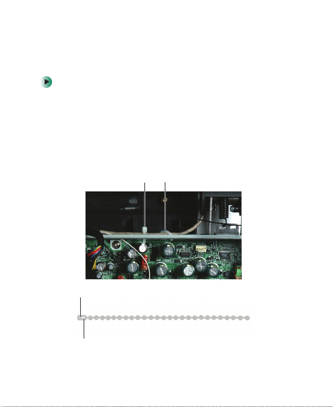
4 Remove the reusable cable ties that secure the two video cables to the
chassis.
Cable ties
Then slide the cable out of this hole.
42
www.gateway.com
Page 48

Replacing the LCD p anel assembly
5 Disconnect the video signal (LVDS) cable and video power cable from the
system board.
Video power
cable
Video signal
(LVDS) cable
6 Thread the two video cables through the hole at the top center of the
chassis.
7 Rotate the LCD panel upward as far as it will go.
www.gateway.com
43
Page 49

Replacing Components i n Your Gateway Profile 5
8 Rotate the top of the hinge cover toward you, then pull it away from the
computer.
44
9 Slide the LCD panel down about one inch.
www.gateway.com
Page 50

Replacing the LCD p anel assembly
10 Slide the LCD hinge plate cover to the left, then pull the cover away from
the computer. If the cover is difficult to remove, make sure all six hooks
on the cover have disengaged from the LCD panel.
LCD hinge plate
cover
www.gateway.com
45
Page 51

Replacing Components i n Your Gateway Profile 5
11 Thread the two video cables out from under the crossbar support, then lay
them on top of the crossbar support.
46
www.gateway.com
Page 52

Replacing the LCD p anel assembly
Screws Screws
Insert the cable loop into this hole.
12 Slide the LCD panel all the way up again, then remove the four screws
that secure the hinge to the LCD panel.
13 Lift the LCD panel straight up and off the hooks.
14 Place the new LCD panel onto the hinge so the panel’s hooks engage the
slots on the hinge plate.
15 Secure the LCD panel to the hinge plate with the four screws you removed
previously.
16 Thread the two video cables through the hole in the top center of the
chassis, then plug the cables into the system board.
17 Tighten the reusable cable ties to secure the video cables to the top of the
chassis.
Then slide the cable in to this l ocking slot.
18 Slide the LCD panel down about an inch.
19 Press the LCD hinge plate cover’s tabs into the corresponding slots on the
LCD panel, then slide the cover to the right until it locks into place.
20 Snap the LCD hinge cover onto the hinges.
www.gateway.com
47
Page 53

Replacing Components i n Your Gateway Profile 5
21 Reinstall the blower assembly by following the instructions in “Replacing
the blower assembly” on page 14.
22 Reinstall the back panel by following the instructions in “Replacing the
back panel” on page 8.
48
www.gateway.com
Page 54

Replacing the CMOS batter y
Replacing the CMOS battery
Time to complete: 4.5 minutes
To replace the CMOS batter y:
1 Turn off the computer and prepare it by following the instructions in
“Preparing your computer” on page 4.
2 Remove the back panel by following the instructions in “Replacing the
back panel” on page 8.
3 Remove the blower assembly by following the instructions in “Replacing
the blower assembly” on page 14.
4 Remove the CMOS battery by pressing the battery release clip down.
CMOS
battery
Batter y releas e
clip
5 Press the new CMOS battery into place.
www.gateway.com
49
Page 55

Replacing Components i n Your Gateway Profile 5
6 Reinstall the blower assembly by following the instructions in “Replacing
the blower assembly” on page 14.
7 Reinstall the back panel by following the instructions in “Replacing the
back panel” on page 8.
50
www.gateway.com
Page 56

Replacing the system boa rd
Replacing the system board
Time to complete: 11.5 minutes
Tips & Tricks For more stability, place your computer face down to
perform this procedure. Avoid scratching the computer
display by placing it on a towel or other non-abrasive
surface.
To replace the system board:
1 Turn off the computer and prepare it by following the instructions in
“Preparing your computer” on page 4.
2 Remove the back panel by following the instructions in “Replacing the
back panel” on page 8.
3 Remove the I/O panel by following the instructions in “Replacing the I/O
panel” on page 10.
4 Remove the blower assembly by following the instructions in “Replacing
the blower assembly” on page 14.
5 If your computer has a video board covering the Mini PCI card slot, remove
the video board by following the instructions in “Replacing the video
board” on page 33.
6 Remove the Mini PCI card by following the instructions in “Replacing the
Mini PCI card” on page 35.
7 Thread the Mini PCI card’s antenna cables through the hole in the top
center of the chassis.
8 Remove the memory modules and processor by following the instructions
in “Replacing memory modules” on page 26 and “Replacing the processor”
on page 28.
9 Disconnect the ribbon cables to the optical drive and the diskette drive
by following the instructions in “Replacing the optical drive” on page 16.
and “Replacing the diskette drive” on page 18.
10 Disconnect all remaining cables from the system board. Make note of the
location of the cables, especially the cabling in the lower-left corner of the
system board.
www.gateway.com
51
Page 57

Replacing Components i n Your Gateway Profile 5
11 Remove the screw that secures the system board to the chassis.
Screw
12 Slide the system board about ½ inch to the right, then remove the board
from the chassis.
13 Insert the new board into the chassis, then slide it about ½ inch to the left.
14 Secure the system board to the chassis using the screw you removed
previously.
15 Reconnect all cables you had removed previously.
16 Reinstall the Mini PCI card by following the instructions in “Replacing the
Mini PCI card” on page 35.
17 If your computer had a video board, reinstall it by following the
instructions in “Replacing the video board” on page 33.
52
www.gateway.com
Page 58

Replacing the system boa rd
18 Reinstall the memory modules and processor by following the instructions
in “Replacing memory modules” on page 26 and “Replacing the processor”
on page 28.
19 Reinstall the blower assembly by following the instructions in “Replacing
the blower assembly” on page 14.
20 Reinstall the I/O panel by following the instructions in “Replacing the I/O
panel” on page 10.
21 Reinstall the back panel by following the instructions in “Replacing the
back panel” on page 8.
www.gateway.com
53
Page 59

Page 60

MAN US PFL5 SERVICE GDE R0 11/03
 Loading...