

Page 1
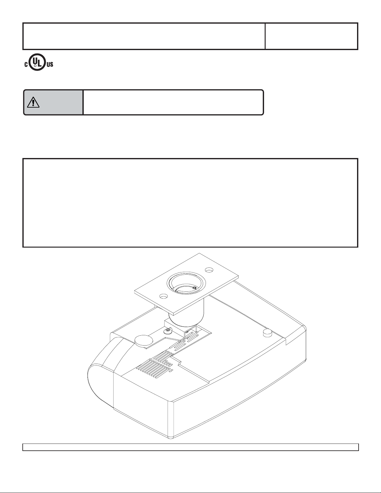
Installation and Assembly - Security Projector Mount
for Gateway™ 210 Projector
This product is intended for use with UL
R
Listed products and must be installed
by a qualified professional installer.
Maximum Load Capacity: 20 lb (9.1 kg)
Model: PJ-G210
Reference Gateway 8007000
Read instruction sheet before you start installation and assembly .
Installer must verify that the ceiling will safely support
W ARNING
the combined weight of projector mount and projector.
IMPORTANT! Be sure not to touch the projector while tightening the set screw on the
ball and socket mount. This may cause the image to be unaligned when you let go.
IMPORTANT! Turn to the appropriate page for your application and ceiling condition.
Three Different Applications:
Flush Mount..................................................................................................................................... step 3, page 5
Threaded Rod ..................................................................................................................................step 4, page 5
Extension Column........................................................................................................................................ page 6
Installation Conditions:
To Wood Joist Finished Ceilings,
Exposed Wood Joists, or Wood Beam Ceilings........................................................................................ page 3
T o Concrete Ceilings.................................................................................................................................... page 4
1 of 8
Visit the Peerless Web Site at www.peerlessindustries.com For customer service call 1-800-729-0307 or 708-865-8870.
ISSUED: 04-21-03 SHEET #: 055-9158-1
Page 2
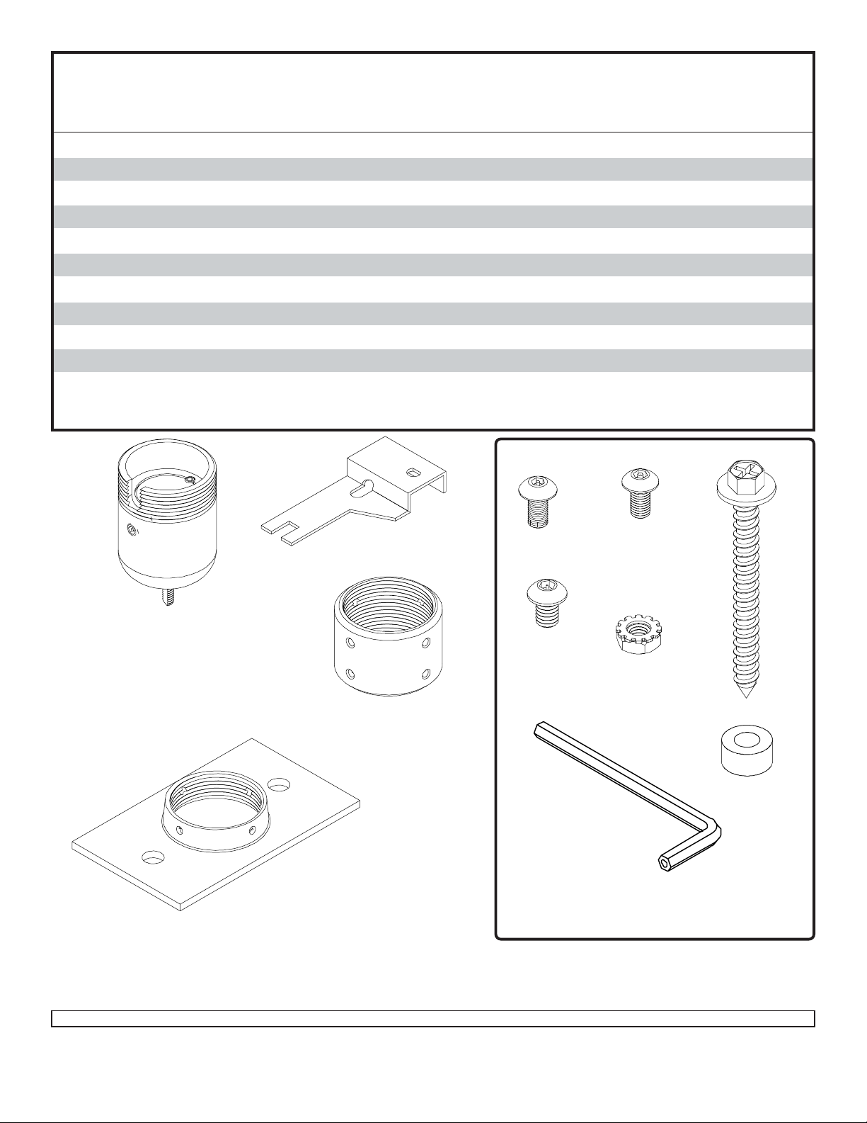
Before you start check the parts list to insure all of the parts shown are included.
Parts List
Description Qty . Part Number
A ball and socket assembly 1 055-0365
B 4 mm security allen wrench 1 560-9646
C M5 x .8 x 10 mm socket pin type F screw 1 520-1 16 4
1
D
/4 - 20 x 3/8 socket pin screw 1 520-1 10 9
E1/4 - 20 x 3/8 nut 1 530-9303
F #14 x 2.5 phillips hex head wood screw 2 5S1-015-C03
G ceiling plate 1 142-1006
H .25" ID x .56" OD x .26 spacer 2 590-1050
I extension column connector 1 580-1013
J 10-32 x 3/8 socket pin screw 2 520-1084
K bracket 1 055-1366
For Missing Parts, contact customer service at 1-800-729-0307.
K
G
A
C
J
D
E
F
I
H
B
Note: Actual parts may appear slightly different than illustrated.
2 of 8
Visit the Peerless Web Site at www.peerlessindustries.com For customer service call 1-800-729-0307 or 708-865-8870.
FASTENERS
ISSUED: 04-21-03 SHEET #: 055-9158-1
Page 3
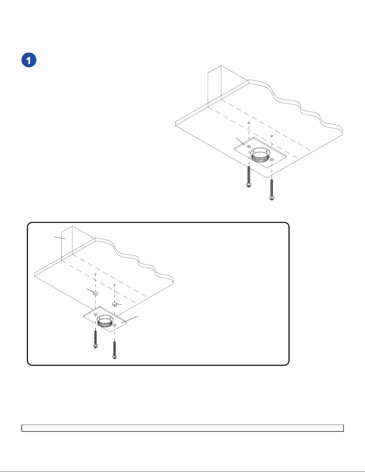
Installation To Wood Joist Finished Ceilings,
Exposed Wood Joists, or Wood Beam Ceilings
Drill two 5/32" (4 mm) dia. holes to a minimum
depth of 2.5" (64 mm). Attach ceiling plate (G)
with two #14 x 2.5" (6 mm x 65 mm) wood
screws (F) as shown using 3/8" (10 mm) socket
wrench. Tighten wood screws (F) so ceiling
plate (G) is firmly attached.
DO NOT TIGHTEN WITH EXCESSIVE FORCE!
Overtightening can cause stress damage to
wood screws (F) greatly reducing their holding
power! Tighten to 80 in • lb (9 N.M.) maximum
torque.
WOOD
JOIST
CEILING
G
WARNING: It is the responsibility of the
installer to verify that the ceiling will safely
support the combined load of all attached
hardware and components.
IMPORTANT: Be sure to drill holes into the
joist CENTER!
F
F
WOOD
JOIST
H
F
CEILING
For optional Cord Management,
install two spacers (H) between ceiling
plate (G) and ceiling.
H
G
F
3 of 8
Visit the Peerless Web Site at www.peerlessindustries.com For customer service call 1-800-729-0307 or 708-865-8870.
ISSUED: 04-21-03 SHEET #: 055-9158-1
Page 4

Installation to Concrete Ceilings
ACC 203 (Alligator® concrete anchors) are recommended.
Drill two 1/4" (6 mm) dia. holes to a minimum
depth of 2.5" (64 mm). Attach ceiling plate (G)
using two concrete anchors and #14 x 2.5" wood
screws (F) as shown in Illustration A and 1, 2,
and 3 (below). Tighten all fasteners.
IMPORTANT: It is the responsibility of the
installer to verify that the ceiling will safely
support the combined load of all attached
hardware and components.
CAUTION: Tighten wood screws so ceiling plate
(G) is firmly attached. But DO NOT TIGHTEN
WITH EXCESSIVE FORCE! Overtightening can
cause stress damage to wood screws, greatly
reducing their holding power! Tighten to 80 in •
lb (9 N.M.) maximum torque.
concrete
anchor
CONCRETE CEILING
G
1
Drill hole and insert anchor
2
G
F
Place ceiling plate over anchor and secure with screw
concrete
ceiling
concrete
anchor
concrete
anchor
3
concrete
F
After repeating step one tighten all fasteners
anchor
F
Illustration A
FOR DIRECT A TT ACHMENT TO LOAD BEARING CONCRETE
ONLY! Concrete expansion anchors are not intended for
attachment to concrete ceilings covered with a layer of plaster ,
drywall, or other finishing material. If mounting to concrete
ceiling covered with plaster / drywall is unavoidable, plaster /
drywall must be counterbored as shown below.
metal
bracket
INCORRECT
concrete
metal
bracket
CORRECT
concrete
plaster/
CUT AW A Y VIEW
4 of 8
Visit the Peerless Web Site at www.peerlessindustries.com For customer service call 1-800-729-0307 or 708-865-8870.
dry wall
ISSUED: 04-21-03 SHEET #: 055-9158-1
plaster/
dry wall
Page 5

Flush Mount Application
Screw ball and socket assembly (A) into ceiling plate (G). Align the
notch with one of the four holes of the ceiling plate (G) and secure
ball and socket assembly (A) with a M5 x 10 mm socket pin
screw (C) using security allen wrench (B) as shown in detail 1.
Skip to step 6.
WOOD
JOIST
CEILING
G
A
B
C
A
DETAIL 1
1/2 -13 THREADED ROD
NOTCH
G
THREADED
ROD
ACC 810
Installation to
Threaded Rod
Accessory ACC 810, threaded rod adapter, is
required. (Sold Separately)
Screw ACC 810 into extension column
connector (I). Align slot in ACC 810 with one of
the top holes in extension column connector (I).
Insert and tighten one 10-32 x 3/8 socket pin
screw (J) through extension column connector
(I) into slot on ACC 810 using 4 mm security
allen wrench (B). See detail 2.
Align slot in ball and socket mount (A) to one of
the bottom holes in extension column connector
(I). Insert and tighten one 10-32 x 3/8 socket pin
screw (J) through extension column connector
(I) into slot in ball and socket mount (A).
See detail 3.
Skip to step 6.
A
SLOT
SLOT
ACC 810
I
I
DETAIL 2
SLOT
J
SLOT
J
THREADED
ROD
ACC 810
I
A
DETAIL 3
5 of 8
Visit the Peerless Web Site at www.peerlessindustries.com For customer service call 1-800-729-0307 or 708-865-8870.
ISSUED: 04-21-03 SHEET #: 055-9158-1
Page 6

Installation to
Extension Column
G
C
Screw extension column to ceiling plate (G).
Align the notch with one of the four holes in
the ceiling plate (G) and secure extension
column with a M5 x 10 mm socket pin
screw (C) using security allen wrench (B).
See detail 4.
Screw extension column connector (I) to
extension column. Align slot in extension
column with one of the top holes in
extension column connector (I). Insert and
tighten one 10-32 x 3/8 socket pin screw (J)
through extension column connector (I) into
slot on extension column using security
allen wrench (B). See detail 5.
Screw ball and socket mount (A) to
extension column connector (I). Align slot in
ball and socket mount (A) to one of the
bottom holes in extension column connector
(I). Insert and tighten one 10-32 x 3/8 socket
pin screw (J) through extension column
connector into slot in ball and socket mount
(A) using security allen wrench (B).
See detail 6.
EXTENSION
COLUMN (SOLD
SEPARA TELY)
SLOT
I
G
EXTENSION
COLUMN
DETAIL 4
EXTENSION
COLUMN
SLOT
ACC 850 - EXTENSION COLUMN CONNECTOR
WITH CORD MANAGEMENT - MA Y BE USED IN
PLACE OF EXTENSION COLUMN CONNECTOR (I).
THIS ALLOWS INST ALLER TO ROUTE CORDS UP
THROUGH THE EXTENSION COLUMN.
(SOLD SEPARA TEL Y)
A
SLOT
I
DETAIL 5
I
A
J
EXTENSION
COLUMN
SLOT
J
DETAIL 6
6 of 8
Visit the Peerless Web Site at www.peerlessindustries.com For customer service call 1-800-729-0307 or 708-865-8870.
ISSUED: 04-21-03 SHEET #: 055-9158-1
Page 7

Attach bracket (K) to ball and socket assembly (A)
using 1/4 - 20 nut (E).
A
To adjust roll, pitch, and yaw loosen the set screw
(shown below) using security allen wrench (B) or
standard 4 mm allen wrench. You should be able to
just slightly loosen the screw so that your adjustments
can be set without having to hold the projector. Move
projector to desired position and slowly tighten set
screw.
Note: Be sure not to touch the projector while
tightening the set screw. This may cause the image
to be unaligned when you let go.
K
E
Press button on side of projector to lift projector foot.
Slide bracket (K) under projector foot. Push foot
down. Secure bracket (K) with 1/4 - 20 socket pin
screw (D).
CEILING
CUTA W A Y VIEW OF
CEILING PLA TE (G)
WOOD
JOIST
D
IMPORTANT: Security allen wrench (B) is your key for
projector removal. Store it in a safe place.
WOOD
JOIST
CEILING
SET SCREW
PROJECTOR
A
PROJECTOR
K
PROJECTOR
FOOT
7 of 8
Visit the Peerless Web Site at www.peerlessindustries.com For customer service call 1-800-729-0307 or 708-865-8870.
© 2003 Peerless Industries, Inc. All rights reserved.
ISSUED: 04-21-03 SHEET #: 055-9158-1
Page 8

PEERLESS LIMITED W ARRANTY
Peerless warrants its products, under normal use, to be free from defects in material and workmanship for a period of five years
from the date of purchase. Peerless, at its sole discretion, will repair or replace such defective equipment free of charge provided
the products are returned prepaid to Peerless. Thereafter, repairs will be made at established factory prices. Unauthorized service
or repairs by anyone other than authorized Peerless personnel renders this W arranty void and releases Peerless from any further
responsibility or obligation. Any damage caused by failure to observe proper packing or to observe instructions for installation, by
accident or in transit or elsewhere will not be covered by the W arranty. This W arranty is in lieu of all other W arranties expressed
or implied, and no one is authorized to assume any liability on behalf of Peerless or impose any obligation on it in connection with
the sale of any product other than as outlined above. In no event will responsibility be assumed or implied for consequential
damages arising from the theft of any product secured by a Peerless security device, by delay of installation, interrupted operation
or other causes.
8 of 8
Visit the Peerless Web Site at www.peerlessindustries.com For customer service call 1-800-729-0307 or 708-865-8870.
ISSUED: 04-21-03 SHEET #: 055-9158-1
 Loading...