

Page 1
Replaci
ng the
AC Adapter
Replacing the AC Adapter
To connect the AC adapter:
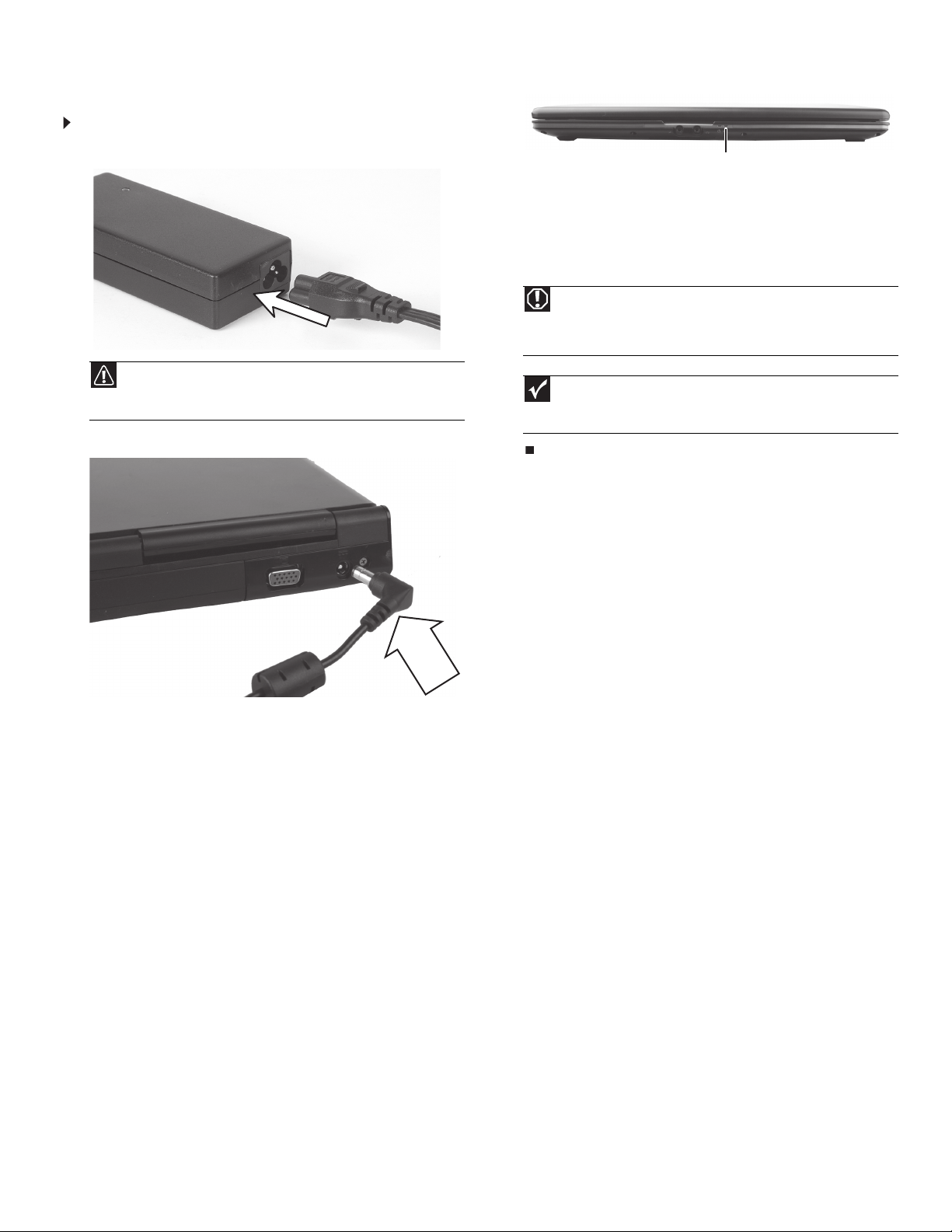
1 Connect the power cord to the AC adapter.
Caution
Replace the power cord if it becomes damaged. The replacement cord
must be of the same type and voltage rating as the original cord or your
notebook may be damaged.
2 Connect the AC adapter to your notebook’s power connector.
3 Plug the power cord into an AC power outlet. The battery charge
indicator turns on.
Battery charge indicator
If the battery charge indicator does not turn on:
• Unplug the adapter from your notebook, then plug it back in.
•Press
• Make sure the power cord is firmly attached to the AC
• Plug the power cord into a different wall outlet.
FN+F1 to toggle the status lights on and off.
adapter.
Warning
Do not attempt to disassemble the AC adapter. The AC adapter has
no user-replaceable or user-serviceable parts inside. The AC adapter has
dangerous voltages that can cause serious injury or death. Contact Gateway
about returning defective AC adapters.
Important
If the battery charge indicator does not turn blue after three hours,
contact Gateway Customer Care at the Web address or telephone number
shown on the label on the bottom of your notebook.
1
Technical Support
See the label on the bottom of the notebook for Customer Care Information. See
your Reference Guide for important safety, regulatory, and legal information.
© 2007 Gateway, Inc. All rights reserved. Gateway and eMachines are trademarks
or registered trademarks of Gateway, Inc. in the United States and other countries.
All other brands and product names are trademarks or registered trademarks of
their respective companies.
Page 2
Replaci
ng the Battery
1
Replacing the Battery
Important
If your notebook is connected to AC power, you can replace the
battery while your notebook is turned on.
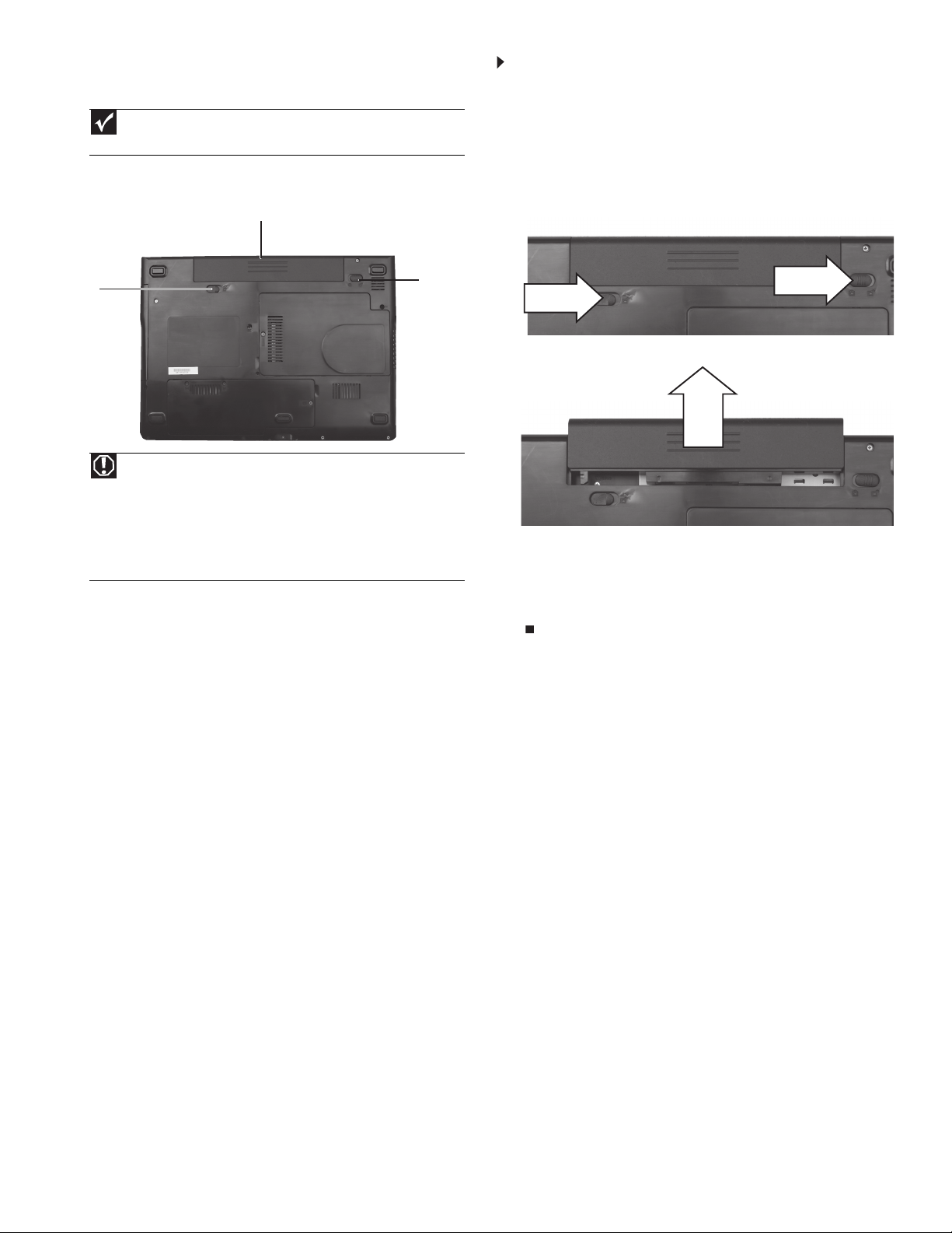
Locating Components
Battery
Battery
latch
Warning
Danger of explosion if the battery is incorrectly replaced.
Replace only with a battery specifically manufactured for your notebook.
Recycle or dispose of the battery as hazardous waste.
The battery used in this device may present a fire or chemical burn hazard
if mishandled. Do not disassemble, heat above 212°F (100°C), or incinerate.
Keep away from children.
Battery
lock
To replace the battery:
1 If your notebook is on and is connected to AC power, go to Step 2.
-OR-
If your notebook is on and is not plugged into an AC outlet, save
your work and turn off your notebook.
2 Turn your notebook over so the bottom is facing up.
3 Slide the battery lock to the unlocked position, then slide the
battery latch.
4 Slide the battery out of your notebook.
5 Slide a recharged battery into your notebook until it snaps into
place.
6 Slide the battery lock to the locked position.
7 Turn your notebook over.
8 Open the LCD panel.
Technical Support
See the label on the bottom of the notebook for Customer Care Information. See
your Reference Guide for important safety, regulatory, and legal information.
© 2007 Gateway, Inc. All rights reserved. Gateway and eMachines are trademarks
or registered trademarks of Gateway, Inc. in the United States and other countries.
All other brands and product names are trademarks or registered trademarks of
their respective companies.
Page 3
Replaci
ng the
DVD drive
Replacing the DVD drive
Tools
You need a small Phillips screwdriver to replace the DVD drive.
1
8 Remove the screw that secures the DVD drive to your notebook.
Important
The location of the screw varies by model.
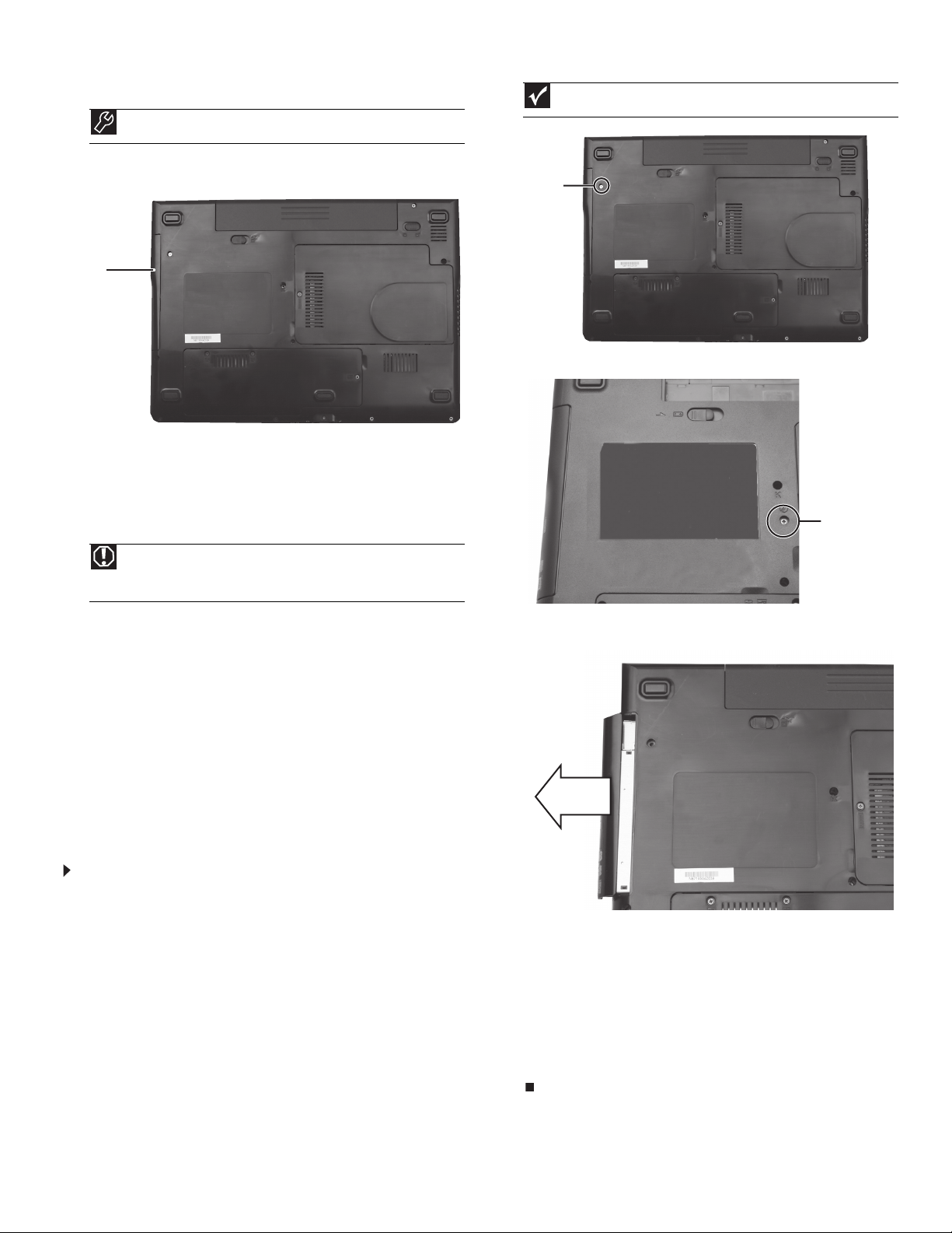
Locating Components
DVD
drive
Preventing static electricity discharge
The components inside your notebook are extremely sensitive to static
electricity, also known as electrostatic discharge (ESD). ESD can
permanently damage electrostatic discharge-sensitive components in
your notebook.
Warning
To avoid exposure to dangerous electrical voltages and moving parts,
turn off your notebook and unplug the AC adapter, modem cable, and
network cable and remove the battery before replacing a component.
Before working with notebook components, follow these guidelines:
• Avoid static-causing surfaces such as carpeted floors, plastic,
and packing foam.
• Remove components from their antistatic bags only when
you are ready to use them. Do not lay components on the
outside of antistatic bags because only the inside of the bags
provide electrostatic protection.
• Always hold components by their edges. Avoid touching the
edge connectors. Never slide components over any surface.
• Wear a grounding wrist strap (available at most electronics
stores) and attach it to a bare metal part of your workbench
or other grounded connection.
• Touch a bare metal surface on your workbench or other
grounded object.
Screw
-OR-
Screw
9 Carefully slide the drive out of the drive bay.
To replace the DVD drive:
1 Follow the guidelines under “Preventing static electricity
discharge.”
2 Make sure that the DVD drive is empty.
3 Turn off your notebook.
4 Close the LCD panel.
5 Disconnect the AC adapter, modem cable, and network cable.
6 Disconnect all peripheral devices connected to your notebook and
remove any Express and memory cards.
7 Turn your notebook over so the bottom is facing up, then remove
the battery. For more information, see “Changing Batteries” in
your Reference Guide.
Technical Support
See the label on the bottom of the notebook for Customer Care Information. See
your Reference Guide for important safety, regulatory, and legal information.
10 Slide the new DVD drive into the drive bay. Make sure that the
drive fits securely in the bay.
11 Replace the screw removed in Step 8.
12 Insert the battery, then turn your notebook over.
13 Connect the power adapter, modem cable, and network cable.
14 Reconnect all peripheral devices and replace any Express and
memory cards.
15 Turn on your notebook.
© 2007 Gateway, Inc. All rights reserved. Gateway and eMachines are trademarks
or registered trademarks of Gateway, Inc. in the United States and other countries.
All other brands and product names are trademarks or registered trademarks of
their respective companies.
Page 4
Replaci
ng the hard driv
e
1
Replacing the hard drive
Tools
You need a small Phillips screwdriver to replace the hard drive. You
also need the operating system disc that came with your notebook.
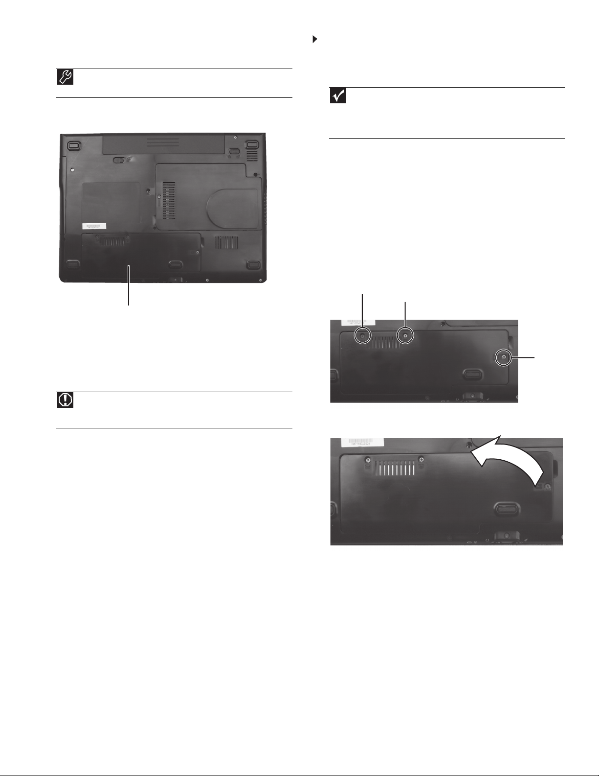
Locating Components
Hard drive bay
To replace the hard drive:
1 If possible, create a Drivers and Applications Recovery disc. For
more information, see “Preparing for software and device driver
recovery” in the Reference Guide.
Important
If you cannot create a Drivers and Applications Recovery disc,
Gateway may send you a set of recovery discs or a replacement hard drive
with the drivers and applications already installed. Contact Gateway
Customer Care at the Web address or telephone number shown on the label
on the bottom of your notebook.
2 Follow the guidelines under “Preventing static electricity
discharge.”
3 Turn off your notebook.
4 Close the LCD panel.
5 Disconnect the AC adapter, modem cable, and network cable.
6 Disconnect all peripheral devices connected to your notebook and
remove any Express and memory cards.
7 Turn y our notebook ov er so the bottom is facing up, then remov e
the battery. For more information, see “Changing Batteries” in
your Reference Guide.
8 Loosen the three hard drive bay cover screws (these screws
cannot be removed).
Screw
Screw
Preventing static electricity discharge
The components inside your notebook are extremely sensitive to static
electricity, also known as electrostatic discharge (ESD). ESD can
permanently damage electrostatic discharge-sensitive components in
your notebook.
Warning
To avoid exposure to dangerous electrical voltages and moving parts,
turn off your notebook and unplug the AC adapter, modem cable, and
network cable and remove the battery before replacing a component.
Before working with notebook components, follow these guidelines:
• Avoid static-causing surfaces such as carpeted floors, plastic,
and packing foam.
• Remove components from their antistatic bags only when
you are ready to use them. Do not lay components on the
outside of antistatic bags because only the inside of the bags
provide electrostatic protection.
• Always hold components by their edges. Avoid touching the
edge connectors. Never slide components over any surface.
• Wear a grounding wrist strap (available at most electronics
stores) and attach it to a bare metal part of your workbench
or other grounded connection.
• Touch a bare metal surface on your workbench or other
grounded object.
Screw
9 Lift the hard drive bay cover using the thumb notch, then remove
it.
Technical Support
See the label on the bottom of the notebook for Customer Care Information. See
your Reference Guide for important safety, regulatory, and legal information.
© 2007 Gateway, Inc. All rights reserved. Gateway and eMachines are trademarks
or registered trademarks of Gateway, Inc. in the United States and other countries.
All other brands and product names are trademarks or registered trademarks of
their respective companies.
Page 5

Replaci
ng the hard driv
e
10 Remove the two screws connecting the hard drive to your
notebook.
Important
The location of the screws varies by model.
2
12 Remove the four screws that secure the hard drive to the hard
drive bracket.
Screw
Screw
-OR-
Screw
Screw
11 Using the plastic tab, slide the old hard drive, then remove it.
Screw
Screw
13 Remove the bracket from the old drive.
Screw
Screw
Technical Support
See the label on the bottom of the notebook for Customer Care Information. See
your Reference Guide for important safety, regulatory, and legal information.
14 Place the new drive, label side up, onto the bracket so the screw
holes line up.
15 Replace the screws removed in Step 12.
16 Slide the new hard drive kit into your notebook.
17 Replace the screws removed in Step 10.
18 Replace the hard drive bay cover, then tighten the cover screws.
19 Insert the battery, then turn your notebook over.
20 Connect the power adapter, modem cable, and network cable
21 Turn on your notebook, open the DVD drive, insert the Windows
DVD, close the DVD drive, then restart your notebook.
22 When the prompt “Press any key to boot from CD or DVD”
appears, press any key on your keyboard and follow the
on-screen instructions. As part of the process you may be
prompted to insert your Drivers and Applications Recovery disc.
23 Reconnect all peripheral devices and replace any Express cards.
© 2007 Gateway, Inc. All rights reserved. Gateway and eMachines are trademarks
or registered trademarks of Gateway, Inc. in the United States and other countries.
All other brands and product names are trademarks or registered trademarks of
their respective companies.
Page 6

Replaci
ng the keyboar
d
Replacing the keyboard
Tools
You need a small Phillips and a small flat-blade screwdriver to replace
the keyboard.
Preventing static electricity discharge
The components inside your notebook are extremely sensitive to static
electricity, also known as electrostatic discharge (ESD). ESD can
permanently damage electrostatic discharge-sensitive components in
your notebook.
1
8 With a small Phillips screwdriver, remove the optional keyboard
cover screw from the inside of the battery compartment and put
it in a safe place.
Screw
Warning
To avoid exposure to dangerous electrical voltages and moving parts,
turn off your notebook and unplug the AC adapter, modem cable, and
network cable and remove the battery before replacing a component.
Before working with notebook components, follow these guidelines:
• Avoid static-causing surfaces such as carpeted floors, plastic,
and packing foam.
• Remove components from their antistatic bags only when
you are ready to use them. Do not lay components on the
outside of antistatic bags because only the inside of the bags
provide electrostatic protection.
• Always hold components by their edges. Avoid touching the
edge connectors. Never slide components over any surface.
• Wear a grounding wrist strap (available at most electronics
stores) and attach it to a bare metal part of your workbench
or other grounded connection.
• Touch a bare metal surface on your workbench or other
grounded object.
To replace the keyboard:
1 Follow the guidelines under “Preventing static electricity
discharge.”
2 Turn off your notebook.
3 Close the LCD panel.
4 Disconnect the AC adapter, modem cable, and network cable.
5 Disconnect all peripheral devices connected to your notebook and
remove any Express and memory cards.
6 Turn your notebook over so the bottom is facing up, then remove
the battery. For more information, see “Changing Batteries” in
your Reference Guide.
7 With a small Phillips screwdriver, remove the keyboard screw and
put it in a safe place.
9 Turn your notebook over so the top is facing up.
10 Open the LCD panel to the fully opened position.
11 Insert the small flat-blade screwdriver under the left end of the
keyboard cover and gently pry it up.
12 Pull the cover off your notebook. Be careful to not damage the
LCD panel.
Caution
Depending on the keyboard cover type, the cover may be connected
to your notebook by a cable. Do not disconnect the cable from the cover
or notebook.
13 With a small Phillips screwdriver, remove the two optional
keyboard screws and put them in a safe place.
Screw
14 Lift the back edge of the keyboard slightly, then slowly slide it
toward the LCD panel to release the keyboard retaining tabs
located on the front edge of the keyboard.
Screw
Screw
Important
The keyboard screw hole is marked with a K.
Technical Support
See the label on the bottom of the notebook for Customer Care Information. See
your Reference Guide for important safety, regulatory, and legal information.
© 2007 Gateway, Inc. All rights reserved. Gateway and eMachines are trademarks
or registered trademarks of Gateway, Inc. in the United States and other countries.
All other brands and product names are trademarks or registered trademarks of
their respective companies.
Page 7

Replaci
ng the keyboar
d
15 Slide the brown keyboard connector clips to the back of your
notebook, then slide the cable out of the clips. Be careful not to
touch or damage any other components.
2
19 Insert the tabs on the front edge of the keyboard into the slots
under the palm rest. You may need to press down on the
keyboard keys along the front edge of the keyboard to seat the
retaining tabs into their corresponding slots.
Clip
Clip
16 Remove the old keyboard.
17 Place the new keyboard keys-up on your notebook with the
space bar toward you.
18 Make sure the brown keyboard connector clips are fully moved
toward the back of your notebook, insert the cable into the
connector, then slide the brown clips to lock the connector in
place.
Important
The keyboard cable is correctly oriented if it is not twisted.
20 Gently press the keyboard down until it is flat all the way across.
The keyboard should easily fall into place. Be careful to not
damage the LCD panel.
21 Replace the optional screws removed in Step 13.
22 Replace the keyboard cover. Press down on the cover in several
places until it clicks in place. The cover is correctly mounted when
you can run you finger along the cover and find no loose spots.
The cover should be flat all the way across.
Caution
If the cover is not correctly replaced, your notebook could be
damaged when you try to close the LCD panel.
23 Close the LCD panel.
24 Turn your notebook over so the bottom is facing up.
25 Replace the optional screw removed in Step 8.
26 Replace the screw removed in Step 7.
27 Insert the battery, then turn your notebook over.
28 Connect the power adapter, modem cable, and network cable
29 Reconnect all peripheral devices and replace any Express cards.
Technical Support
See the label on the bottom of the notebook for Customer Care Information. See
your Reference Guide for important safety, regulatory, and legal information.
© 2007 Gateway, Inc. All rights reserved. Gateway and eMachines are trademarks
or registered trademarks of Gateway, Inc. in the United States and other countries.
All other brands and product names are trademarks or registered trademarks of
their respective companies.
Page 8

Replaci
ng a Memory Modu
le
1
Replacing a Memory Module
Tools
You need a small Phillips screwdriver to replace a memory module.
Locating Components
Memory
bay
Preventing static electricity discharge
The components inside your notebook are extremely sensitive to static
electricity, also known as electrostatic discharge (ESD). ESD can
permanently damage electrostatic discharge-sensitive components in
your notebook.
To replace a memory module:
1 Follow the guidelines under “Preventing static electricity
discharge.”
2 Turn off your notebook.
3 Close the LCD panel.
4 Disconnect the AC adapter, modem cable, and network cable.
5 Disconnect all peripheral devices connected to your notebook and
remove any Express and memory cards.
6 Turn y our notebook ov er so the bottom is facing up, then remov e
the battery. For more information, see “Changing Batteries” in
your Reference Guide.
7 Loosen the memory bay cover screw (this screw cannot be
removed).
Screw
8 Lift the memory bay cover, then remove it.
Warning
To avoid exposure to dangerous electrical voltages and moving parts,
turn off your notebook and unplug the AC adapter, modem cable, and
network cable and remove the battery before replacing a component.
Before working with notebook components, follow these guidelines:
• Avoid static-causing surfaces such as carpeted floors, plastic,
and packing foam.
• Remove components from their antistatic bags only when
you are ready to use them. Do not lay components on the
outside of antistatic bags because only the inside of the bags
provide electrostatic protection.
• Always hold components by their edges. Avoid touching the
edge connectors. Never slide components over any surface.
• Wear a grounding wrist strap (available at most electronics
stores) and attach it to a bare metal part of your workbench
or other grounded connection.
• Touch a bare metal surface on your workbench or other
grounded object.
Technical Support
See the label on the bottom of the notebook for Customer Care Information. See
your Reference Guide for important safety, regulatory, and legal information.
© 2007 Gateway, Inc. All rights reserved. Gateway and eMachines are trademarks
or registered trademarks of Gateway, Inc. in the United States and other countries.
All other brands and product names are trademarks or registered trademarks of
their respective companies.
Page 9
Replaci
ng a Memory Modu
le
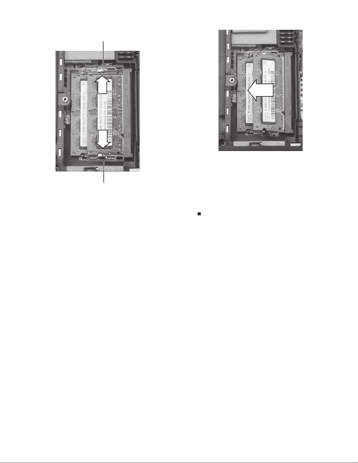
9 If you are removing a module, gently press outward on the clip
at each end of the memory module until the module tilts upward.
Clip
Clip
2
10 Pull the memory module out of the slot.
11 Hold the new or replacement module at a 30-degree angle and
press it into the empty memory slot. This module is keyed so it
can only be inserted in one direction. If the module does not fit,
make sure that the notch in the module lines up with the tab in
the memory bay.
12 Replace the memory bay cover, then tighten the cover screw.
13 Insert the battery, then turn your notebook over.
14 Connect the power adapter, modem cable, and network cable
15 Reconnect all peripheral devices and replace any Express cards.
Technical Support
See the label on the bottom of the notebook for Customer Care Information. See
your Reference Guide for important safety, regulatory, and legal information.
© 2007 Gateway, Inc. All rights reserved. Gateway and eMachines are trademarks
or registered trademarks of Gateway, Inc. in the United States and other countries.
All other brands and product names are trademarks or registered trademarks of
their respective companies.
Page 10

Replaci
ng the Mu
ltimedia Keyb
r
oard Cove
Replacing the Multimedia Keyboard Cover
Tools
You need a small Phillips and a small flat-blade screwdriver to replace
the multimedia keyboard cover.
Preventing static electricity discharge
The components inside your notebook are extremely sensitive to static
electricity, also known as electrostatic discharge (ESD). ESD can
permanently damage electrostatic discharge-sensitive components in
your notebook.
Warning
To avoid exposure to dangerous electrical voltages and moving parts,
turn off your notebook and unplug the AC adapter, modem cable, and
network cable and remove the battery before replacing a component.
Before working with notebook components, follow these guidelines:
• Avoid static-causing surfaces such as carpeted floors, plastic,
and packing foam.
• Remove components from their antistatic bags only when
you are ready to use them. Do not lay components on the
outside of antistatic bags because only the inside of the bags
provide electrostatic protection.
• Always hold components by their edges. Avoid touching the
edge connectors. Never slide components over any surface.
• Wear a grounding wrist strap (available at most electronics
stores) and attach it to a bare metal part of your workbench
or other grounded connection.
• Touch a bare metal surface on your workbench or other
grounded object.
To replace the multimedia keyboard cover:
1 Follow the guidelines under “Preventing static electricity
discharge.”
2 Turn off your notebook.
3 Close the LCD panel.
4 Disconnect the AC adapter, modem cable, and network cable.
5 Disconnect all peripheral devices connected to your notebook and
remove any Express and memory cards.
6 Turn your notebook over so the bottom is facing up, then remove
the battery. For more information, see “Changing Batteries” in
your Reference Guide.
7 With a small Phillips screwdriver, remove the keyboard screw and
put it in a safe place.
8 With a small Phillips screwdriver, remove the optional keyboard
cover screw from the inside of the battery compartment and put
it in a safe place.
Screw
9 Turn your notebook over so the top is facing up.
10 Open the LCD panel to the fully opened position.
11 Insert the small flat-blade screwdriver under the left end of the
keyboard cover and gently pry it up.
12 Pull the cover off your notebook. Be careful to not damage the
LCD panel.
Caution
The cover is connected to your notebook by a cable. Do not pull on
the cable.
13 With a small Phillips screwdriver, remove the two optional
keyboard screws and put them in a safe place.
Screw
14 Lift the back edge of the keyboard slightly, then slowly slide it
toward the LCD panel to release the keyboard retaining tabs
located on the front edge of the keyboard.
Screw
1
Screw
Important
The keyboard screw hole is marked with a K.
Technical Support
See the label on the bottom of the notebook for Customer Care Information. See
your Reference Guide for important safety, regulatory, and legal information.
© 2007 Gateway, Inc. All rights reserved. Gateway and eMachines are trademarks
or registered trademarks of Gateway, Inc. in the United States and other countries.
All other brands and product names are trademarks or registered trademarks of
their respective companies.
Page 11

Replaci
ng the Mu
ltimedia Keyb
r
oard Cove
15 Slowly rotate the keyboard toward you so it lies keys-down on
top of your notebook. Be careful to not damage the LCD panel.
Caution
The keyboard is connected to your notebook by a cable. Do not
disconnect the cable from your notebook.
16 Slide the brown multimedia keyboard cover connector clips to the
back of your notebook, then slide the cable out of the clips. Be
careful not to touch or damage any other components.
2
19 Insert the tabs on the front edge of the keyboard into the slots
under the palm rest. You may need to press down on the
keyboard keys along the front edge of the keyboard to seat the
retaining tabs into their corresponding slots.
20 Gently press the keyboard down until it is flat all the way across.
The keyboard should easily fall into place. Be careful to not
damage the LCD panel.
21 Replace the optional screws removed in Step 13.
22 Replace the multimedia keyboard cover. Press down on the cover
in several places until it clicks in place. The cover is correctly
mounted when you can run you finger along the cover and find
no loose spots. The cover should be flat all the way across.
Clip
Clip
17 Remove the old cover.
18 Make sure the brown multimedia keyboard cover connector clips
are fully moved toward the back of your notebook, insert the
cable from the new cover into the connector, then slide the brown
clips to lock the connector in place.
Important
The cable is correctly oriented if it is not twisted.
Caution
If the cover is not correctly replaced, your notebook could be
damaged when you try to close the LCD panel.
23 Close the LCD panel.
24 Turn your notebook over so the bottom is facing up.
25 Replace the optional screw removed in Step 8.
26 Replace the screw removed in Step 7.
27 Insert the battery, then turn your notebook over.
28 Connect the power adapter, modem cable, and network cable
29 Reconnect all peripheral devices and replace any Express cards.
Technical Support
See the label on the bottom of the notebook for Customer Care Information. See
your Reference Guide for important safety, regulatory, and legal information.
© 2007 Gateway, Inc. All rights reserved. Gateway and eMachines are trademarks
or registered trademarks of Gateway, Inc. in the United States and other countries.
All other brands and product names are trademarks or registered trademarks of
their respective companies.
Page 12

Replaci
ng the Wireless Network Modu
le
1
Replacing the Wireless Network Module
Tools
You need a small Phillips screwdriver to replace the wireless network
module.
Locating Components
Wireless network bay
To replace the wireless network module:
1 Follow the guidelines under “Preventing static electricity
discharge.”
2 Turn off your notebook.
3 Close the LCD panel.
4 Disconnect the AC adapter, modem cable, and network cable.
5 Disconnect all peripheral devices connected to your notebook and
remove any Express and memory cards.
6 Turn y our notebook ov er so the bottom is facing up, then remov e
the battery. For more information, see “Changing Batteries” in
your Reference Guide.
7 Loosen the three wireless network bay cover screws (these
screws cannot be removed).
Screw
8 Lift the wireless network bay cover, then remove it.
Screw
Screw
Preventing static electricity discharge
The components inside your notebook are extremely sensitive to static
electricity, also known as electrostatic discharge (ESD). ESD can
permanently damage electrostatic discharge-sensitive components in
your notebook.
Warning
To avoid exposure to dangerous electrical voltages and moving parts,
turn off your notebook and unplug the AC adapter, modem cable, and
network cable and remove the battery before replacing a component.
Before working with notebook components, follow these guidelines:
• Avoid static-causing surfaces such as carpeted floors, plastic,
and packing foam.
• Remove components from their antistatic bags only when
you are ready to use them. Do not lay components on the
outside of antistatic bags because only the inside of the bags
provide electrostatic protection.
• Always hold components by their edges. Avoid touching the
edge connectors. Never slide components over any surface.
• Wear a grounding wrist strap (available at most electronics
stores) and attach it to a bare metal part of your workbench
or other grounded connection.
• Touch a bare metal surface on your workbench or other
grounded object.
9 Unplug the two or three antenna cables. Note which color cable
is connected to each of the connectors.
Technical Support
See the label on the bottom of the notebook for Customer Care Information. See
your Reference Guide for important safety, regulatory, and legal information.
© 2007 Gateway, Inc. All rights reserved. Gateway and eMachines are trademarks
or registered trademarks of Gateway, Inc. in the United States and other countries.
All other brands and product names are trademarks or registered trademarks of
their respective companies.
Page 13

Replaci
ng the Wireless Network Modu
le
10 Move the antenna cables out of the way.
11 Remove the screws securing the wireless network module.
2
12 Pull the module out of the slot.
Screw
Screw
13 Hold the new module at a 30-degree angle and insert it into the
empty slot. This module is keyed so it can only be inserted in one
direction. If the module does not fit, make sure that the notch in
the module lines up with the tab in the module slot.
14 Move the antenna wires out of the way.
15 Replace the screws removed in Step 11.
16 Reattach the antenna cables to the connectors.
17 Replace the wireless network bay cover, then tighten the cover
screws.
18 Insert the battery, then turn your notebook over.
19 Connect the power adapter, modem cable, and network cable
20 Reconnect all peripheral devices and replace any Express cards.
Technical Support
See the label on the bottom of the notebook for Customer Care Information. See
your Reference Guide for important safety, regulatory, and legal information.
© 2007 Gateway, Inc. All rights reserved. Gateway and eMachines are trademarks
or registered trademarks of Gateway, Inc. in the United States and other countries.
All other brands and product names are trademarks or registered trademarks of
their respective companies.
 Loading...