

Page 1
G1000
®
Integrated Flight Deck
Cockpit Reference Guide
TBM 850 & TBM 900
Page 2

Page 3

FLIGHT INSTRUMENTS
ENGINE & AIRFRAME SYSTEMS
NAV/COM/TRANSPONDER/AUDIO PANEL
AUTOMATIC FLIGHT CONTROL SYSTEM
GPS NAVIGATION
FLIGHT PLANNING
PROCEDURES
HAZARD AVOIDANCE
ADDITIONAL FEATURES
ABNORMAL OPERATION
ANNUNCIATIONS & ALERTS
APPENDIX
INDEX
Page 4

Page 5

Copyright © 2007, 2009-2011, 2014, 2015 Garmin Ltd. or its subsidiaries. All rights
reserved.
This manual reflects the operation of System Software version 0719.12 or later for the Socata
TBM 850/900. Some differences in operation may be observed when comparing the information
in this manual to earlier or later software versions.
Garmin International, Inc., 1200 East 151st Street, Olathe, Kansas 66062, U.S.A.
Tel: 913/397.8200 Fax: 913/397.8282
Garmin AT, Inc., 2345 Turner Road SE, Salem, OR 97302, U.S.A.
Tel: 503/391.3411 Fax 503/364.2138
Garmin (Europe) Ltd.
Liberty House, Hounsdown Business Park, Southampton, Hampshire SO40 9LR U.K.
Tel: 44 (0) 23 8052 4000 Fax: 44 (0) 23 8052 4004
Garmin Corporation, No. 68, Jangshu 2nd Road, Shijr, Taipei County, Taiwan
Tel: 886/02.2642.9199 Fax: 886/02.2642.9099
For after-hours emergency, aircraft on ground (AOG) technical support for Garmin panel mount
and integrated avionics systems, please contact Garmin’s AOG Hotline at 913.397.0836.
Web Site Address: www.garmin.com
Except as expressly provided herein, no part of this manual may be reproduced, copied,
transmitted, disseminated, downloaded or stored in any storage medium, for any purpose
without the express written permission of Garmin. Garmin hereby grants permission to
download a single copy of this manual and of any revision to this manual onto a hard drive or
other electronic storage medium to be viewed for personal use, provided that such electronic
or printed copy of this manual or revision must contain the complete text of this copyright
notice and provided further that any unauthorized commercial distribution of this manual or any
revision hereto is strictly prohibited.
Garmin® and G1000®, WATCH®, FliteCharts®, and SafeTaxi® are registered trademarks of
Garmin Ltd. or its subsidiaries. Connext™ is a trademark of Garmin Ltd. or its subsidiaries.
These trademarks may not be used without the express permission of Garmin.
NavData® is a registered trademark of Jeppesen, Inc.; Stormscope® is a registered trademark
of L-3 Communications.
SiriusXM Weather and SiriusXM Satellite Radio are provided by SiriusXM Satellite Radio, Inc.
AC-U-KWIK® is a registered trademark of Penton Business Media Inc.
Page 6

AOPA Membership Publications, Inc. and its related organizations (hereinafter collectively
“AOPA”) expressly disclaim all warranties, with respect to the AOPA information included in this
data, express or implied, including, but not limited to, the implied warranties of merchantability
and fitness for a particular purpose. The information is provided “as is” and AOPA does not
warrant or make any representations regarding its accuracy, reliability, or otherwise. Under
no circumstances including negligence, shall AOPA be liable for any incidental, special or
consequential damages that result from the use or inability to use the software or related
documentation, even if AOPA or an AOPA authorized representative has been advised of the
possibility of such damages. User agrees not to sue AOPA and, to the maximum extent allowed
by law, to release and hold harmless AOPA from any causes of action, claims or losses related
to any actual or alleged inaccuracies in the information. Some jurisdictions do not allow the
limitation or exclusion of implied warranties or liability for incidental or consequential damages
so the above limitations or exclusions may not apply to you.
AC-U-KWIK and its related organizations (hereafter collectively “AC-U-KWIK Organizations”)
expressly disclaim all warranties with respect to the AC-U-KWIK information included in this
data, express or implied, including, but not limited to, the implied warranties of merchantability
and fitness for a particular purpose. The information is provided “as is” and AC-U-KWIK
Organizations do not warrant or make any representations regarding its accuracy, reliability, or
otherwise. Licensee agrees not to sue AC-U-KWIK Organizations and, to the maximum extent
allowed by law, to release and hold harmless AC-U-KWIK Organizations from any cause of
action, claims or losses related to any actual or alleged inaccuracies in the information arising
out of Garmin’s use of the information in the datasets. Some jurisdictions do not allow the
limitation or exclusion of implied warranties or liability for incidental or consequential damages
so the above limitations or exclusions may not apply to licensee.
January, 2015 190-00708-05 Rev. C Printed in the U.S.A
Page 7

Warnings, Cautions & Notes
WARNING: Navigation and terrain separation must NOT be predicated upon
the use of the terrain avoidance feature. The terrain avoidance feature is NOT
intended to be used as a primary reference for terrain avoidance and does
not relieve the pilot from the responsibility of being aware of surroundings
during flight. The terrain avoidance feature is only to be used as an aid for
terrain avoidance. Terrain data is obtained from third party sources. Garmin
is not able to independently verify the accuracy of the terrain data.
WARNING: The displayed minimum safe altitudes (MSAs) are only advisory
in nature and should not be relied upon as the sole source of obstacle and
terrain avoidance information. Always refer to current aeronautical charts
for appropriate minimum clearance altitudes.
WARNING: Do not use outdated database information. Databases used in
the system must be updated regularly in order to ensure that the information
remains current. Pilots using any outdated database do so entirely at their
own risk.
WARNING: Do not use basemap (land and water data) information for
primary navigation. Basemap data is intended only to supplement other
approved navigation data sources and should be considered as an aid to
enhance situational awareness.
WARNING: Do not rely solely upon the display of traffic information for
collision avoidance maneuvering. The traffic display does not provide collision avoidance resolution advisories and does not under any circumstances
or conditions relieve the pilot’s responsibility to see and avoid other aircraft.
WARNING: Do not rely solely upon the display of traffic information to
accurately depict all of the traffic within range of the aircraft. Due to lack
of equipment, poor signal reception, and/or inaccurate information from
aircraft or ground stations, traffic may be present that is not represented on
the display.
WARNING: Do not use data link weather information for maneuvering in,
near or around areas of hazardous weather. Information contained within
data link weather products may not accurately depict current weather conditions.
190-00708-05 Rev. C
Garmin G1000 Cockpit Reference Guide for the Socata TBM 850/900
Page 8

Warnings, Cautions & Notes
WARNING: Do not use the indicated data link weather product age to deter-
mine the age of the weather information shown by the data link weather
product. Due to time delays inherent in gathering and processing weather
data for data link transmission, the weather information shown by the data
link weather product may be significantly older than the indicated weather
product age.
WARNING: Do not rely on information from the lightning detection system
display as the sole basis for hazard weather avoidance. Range limitations
and interference may cause the system to display inaccurate or incomplete
information. Refer to the documentation from the lightning detection system
manufacturer for detailed information about the system.
WARNING: The system, as installed in the TBM 850/900 aircraft, has a very
high degree of functional integrity. However, the pilot must recognize that
providing monitoring and/or self-test capability for all conceivable system
failures is not practical. Although unlikely, it may be possible for erroneous
operation to occur without a fault indication shown by the system. It is
thus the responsibility of the pilot to detect such an occurrence by means of
cross-checking with all redundant or correlated information available in the
cockpit.
WARNING: For safety reasons, system operational procedures must be
learned on the ground.
WARNING: The United States government operates the Global Positioning
System and is solely responsible for its accuracy and maintenance. The GPS
system is subject to changes which could affect the accuracy and performance
of all GPS equipment. Portions of the system utilize GPS as a precision electronic NAVigation AID (NAVAID). Therefore, as with all NAVAIDs, information
presented by the system can be misused or misinterpreted and, therefore,
become unsafe.
WARNING: Lamp(s) inside this product may contain mercury (HG) and must
be recycled or disposed of according to local, state, or federal laws. For more
information, refer to our website at www.garmin.com/aboutGarmin/environment/disposal.jsp.
Garmin G1000 Cockpit Reference Guide for the Socata TBM 850/900
190-00708-05 Rev. C
Page 9

Warnings, Cautions & Notes
WARNING: To reduce the risk of unsafe operation, carefully review and
understand all aspects of the Pilot’s Guide documentation and the TBM
850/900 Airplane Flight Manual. Thoroughly practice basic operation prior
to actual use. During flight operations, carefully compare indications from
the system to all available navigation sources, including the information
from other NAVAIDs, visual sightings, charts, etc. For safety purposes, always
resolve any discrepancies before continuing navigation.
WARNING: The illustrations in this guide are only examples. Never use
the system to attempt to penetrate a thunderstorm. Both the FAA Advisory
Circular, Subject: Thunderstorms, and the Aeronautical Information Manual
(AIM) recommend avoiding “by at least 20 miles any thunderstorm identified
as severe or giving an intense radar echo.”
WARNING: Because of variation in the earth’s magnetic field, operating the
system within the following areas could result in loss of reliable attitude and
heading indications. North of 72° North latitude at all longitudes. South of
70° South latitude at all longitudes. North of 65° North latitude between
longitude 75° W and 120° W. (Northern Canada). North of 70° North latitude
between longitude 70° W and 128° W. (Northern Canada). North of 70° North
latitude between longitude 85° E and 114° E. (Northern Russia). South of
55° South latitude between longitude 120° E and 165° E. (Region south of
Australia and New Zealand).
WARNING: Do not use GPS to navigate to any active waypoint identified
as a ‘NON WGS84 WPT’ by a system message. ‘NON WGS84 WPT’ waypoints
are derived from an unknown map reference datum that may be incompatible
with the map reference datum used by GPS (known as WGS84) and may be
positioned in error as displayed.
WARNING: Do not use a QFE altimeter setting with this system. System
functions will not operate properly with a QFE altimeter setting. Use only
a QNH altimeter setting for height above mean sea level, or the standard
pressure setting, as applicable.
190-00708-05 Rev. C
Garmin G1000 Cockpit Reference Guide for the Socata TBM 850/900
Page 10
Warnings, Cautions & Notes
CAUTION: The PFD and MFD displays use a lens coated with a special anti-
reflective coating that is very sensitive to skin oils, waxes, and abrasive cleaners. CLEANERS CONTAINING AMMONIA WILL HARM THE ANTI-REFLECTIVE
COATING. It is very important to clean the lens using a clean, lint-free cloth
and an eyeglass lens cleaner that is specified as safe for anti-reflective coatings.
CAUTION: The system does not contain any user-serviceable parts. Repairs
should only be made by an authorized Garmin service center. Unauthorized
repairs or modifications could void both the warranty and the pilot’s authority
to operate this device under FAA/FCC regulations.
NOTE: All visual depictions contained within this document, including screen
images of the panel and displays, are subject to change and may not reflect
the most current system and databases. Depictions of equipment may differ
slightly from the actual equipment.
NOTE: This device complies with part 15 of the FCC Rules. Operation is
subject to the following two conditions: (1) this device may not cause harmful interference, and (2) this device must accept any interference received,
including interference that may cause undesired operation.
NOTE: The data contained in the terrain and obstacle databases comes from
government agencies. Garmin accurately processes and cross-validates the
data, but cannot guarantee the accuracy and completeness of the data.
NOTE: This product, its packaging, and its components contain chemicals
known to the State of California to cause cancer, birth defects, or reproductive
harm. This notice is being provided in accordance with California’s Proposition
65. If you have any questions or would like additional information, please
refer to our web site at www.garmin.com/prop65.
NOTE: Interference from GPS repeaters operating inside nearby hangars can
cause an intermittent loss of attitude and heading displays while the aircraft
is on the ground. Moving the aircraft more than 100 yards away from the
source of the interference should alleviate the condition.
Garmin G1000 Cockpit Reference Guide for the Socata TBM 850/900
190-00708-05 Rev. C
Page 11

Warnings, Cautions & Notes
NOTE: Operating the system in the vicinity of metal buildings, metal
structures, or electromagnetic fields can cause sensor differences that may
result in nuisance miscompare annunciations during start up, shut down, or
while taxiing. If one or both of the sensed values are unavailable, it will be
annunciated as a ‘NO COMP’ (no compare).
NOTE: Use of polarized eyewear may cause the flight displays to appear dim
or blank.
NOTE: The FAA has asked Garmin to remind pilots who fly with Garmin
database-dependent avionics of the following:
• It is the pilot’s responsibility to remain familiar with all FAA regulatory
and advisory guidance and information related to the use of databases in
the National Airspace System.
• Garmin equipment will only recognize and use databases that are
obtained from Garmin or Jeppesen. Databases obtained from Garmin
or Jeppesen are assured compliance with all data quality requirements
(DQRs) by virtue of a Type 2 Letter of Authorization (LOA) from the FAA. A
copy of the Type 2 LOA is available for each database and can be viewed
at http://fly.garmin.com by selecting ‘Type 2 LOA Status.’
• Use of a current Garmin or Jeppesen database in your Garmin equipment
is required for compliance with established FAA regulatory guidance, but
does not constitute authorization to fly any and all terminal procedures
that may be presented by the system. It is the pilot’s responsibility to
operate in accordance with established AFM(S) and regulatory guidance or
limitations as applicable to the pilot, the aircraft, and installed equipment.
NOTE: The pilot/operator must review and be familiar with Garmin’s database
exclusion list as discussed in SAIB CE-14-04 to determine what data may be
incomplete. The database exclusion list can be viewed at www.flygarmin.
com by selecting ‘Database Exclusions List.’
NOTE: The pilot/operator must have access to Garmin and Jeppesen database alerts and consider their impact on the intended aircraft operation. The
database alerts can be viewed at www.flygarmin.com by selecting ‘Aviation
Database Alerts.’
190-00708-05 Rev. C
Garmin G1000 Cockpit Reference Guide for the Socata TBM 850/900
Page 12

Warnings, Cautions & Notes
NOTE: If the pilot/operator wants or needs to adjust the database, contact
Garmin Product Support to coordinate the revised DQRs.
NOTE: Garmin requests the flight crew report any observed discrepancies
related to database information. These discrepancies could come in the form
of an incorrect procedure; incorrectly identified terrain, obstacles and fixes;
or any other displayed item used for navigation or communication in the air
or on the ground. Go to FlyGarmin.com and select ‘Report An Aviation Data
Error Report.’
Garmin G1000 Cockpit Reference Guide for the Socata TBM 850/900
190-00708-05 Rev. C
Page 13

Record of Revisions
Part Number Change Summary
190-00708-00 Initial Release
190-00708-01
Rev A
Added SVS and other GDU 9.02 parameters.
Rev B
Clerical changes
190-00708-02 Added temporary user waypoints
Added import/export flight plans
Added CDI availability during Dead Reckoning mode
Added GDU 9.14 parameters.
190-00708-03
Rev A Added GDU 11.01 parameters.
Added GTS 820
Added AOPA Airport Directory
Added database synchronization
190-00708-04 Added Profile View
Added Standby Navigation Database
Added new database update procedures
Added Iridium Satellite Telephone & SMS messaging
Added GFDS Worldwide Weather
Added WX LGND, LEGEND, and METAR softkeys
Updated system messages
Added other GDU 12.01 parameters
190-00708-05 Rev. C RR-1
Garmin G1000 Cockpit Reference Guide for the Socata TBM 850/900
Page 14
Record of Revisions
Part Number Change Summary
190-00708-05
Rev. A
Added TBM 900
Added Maintenance Log feature
Added Auxiliary Video
Added CPDLC
Added AC-U-KWIK Airport Directory
Added User Defined Holding Patterns
Added Landing Field Elevation enty
Added temperature compensated altitude
Changed GFDS Weather to Connext™ Weather
Changed XM to SiriusXM
Changed Synthetic Vision System (SVS) to Synthetic Vision
Technology (SVT)
Added other GDU 14.01 parameters
Rev. B
Updated Warnings, Cautions, and Notes
Updated CAS Messages
Added a Note to Flight Instruments
Rev. C
Clerical
Revision Date of Revision Affected Pages Description
C January, 2015 All Production Release
RR-2
Garmin G1000 Cockpit Reference Guide for the Socata TBM 850/900
190-00708-05 Rev. C
Page 15

Table of Contents
FLIGHT INSTRUMENTS ................................................................................................................ 1
Selecting the Altimeter Barometric Pressure Setting ...................................................... 1
Selecting Standard Barometric Pressure .............................................................................1
Change Altimeter Barometric Pressure Setting Units ...................................................... 1
Synchronizing the Altimeter Barometric Pressure Settings ........................................... 1
Synchronize CDI......................................................................................................................... 1
Change Navigation Sources ................................................................................................... 2
Enable/Disable OBS Mode While Navigating with GPS .................................................... 2
Generic Timer ............................................................................................................................. 2
Configure Vspeed Bugs ............................................................................................................ 3
Set Barometric/Radar Altimeter Minimum Descent Altitude ......................................... 3
Manually Testing the Radar Altimeter (KRA 405B only) .................................................. 3
Displaying Wind Data .............................................................................................................. 4
Changing HSI Format ............................................................................................................... 4
ENGINE & AIRFRAME SYSTEMS .............................................................................................5
Electrical System ....................................................................................................................... 6
Fuel System ................................................................................................................................ 8
General Systems ..................................................................................................................... 10
Cabin Pressurization .............................................................................................................. 11
NAV/COM/TRANSPONDER/AUDIO PANEL .......................................................................13
Enter or Change Flight ID (Optional) .................................................................................. 13
ADF Tuning (Optional) ............................................................................................................ 13
DME Tuning (Optional) ........................................................................................................... 13
Enter a Transponder Code..................................................................................................... 14
Selecting a COM Radio .......................................................................................................... 14
Selecting a NAV Radio ........................................................................................................... 14
NAV/COM Tuning ..................................................................................................................... 14
Intercom .................................................................................................................................... 15
Controller Pilot Data Link Communications (Optional) ................................................. 15
Passenger Address (PA) System ........................................................................................... 19
Clearance Recorder and Player ........................................................................................... 19
AUTOMATIC FLIGHT CONTROL SYSTEM .......................................................................... 21
Flight Director Activation ..................................................................................................... 21
Vertical Modes .........................................................................................................................22
Lateral Modes .......................................................................................................................... 23
GPS NAVIGATION ........................................................................................................................ 25
Direct-to Navigation .............................................................................................................. 25
Activate a Stored Flight Plan ............................................................................................... 26
Activate a Flight Plan Leg ..................................................................................................... 26
Stop Navigating a Flight Plan .............................................................................................. 27
Vertical Navigation (VNAV)................................................................................................... 27
190-00708-05 Rev. C i
Garmin G1000 Cockpit Reference Guide for the Socata TBM 850/900
Page 16

Table of Contents
FLIGHT PLANNING ...................................................................................................................... 29
Weight Planning ...................................................................................................................... 29
Trip Planning ............................................................................................................................ 29
Create a User Waypoint Defined by Latitude & Longitude ........................................... 31
Create a User Waypoint Defined by Radials from Other Waypoints ........................... 32
Create a User Waypoint Defined by a Radial & Distance from Another Waypoint ..34
Delete a User Waypoint ......................................................................................................... 35
Create a Flight Plan ................................................................................................................ 36
Import a Flight Plan from an SD Card ................................................................................ 37
Insert a Waypoint in the Active Flight Plan ...................................................................... 37
Enter an Airway in a Flight Plan .......................................................................................... 38
Creating a User-Defined Hold at an Active Flight Plan Waypoint ................................ 39
Creating a User-Defined Hold at the Aircraft Present Position .................................... 39
Removing a User-Defined Hold (Created at the Aircraft P.POS) .................................. 40
Removing a User-Defined Hold (Created at an Active Waypoint) ............................... 40
Invert An Active Flight Plan ..................................................................................................40
Remove a Departure, Arrival, Approach, or Airway from a Flight Plan ..................... 41
Store a Flight Plan .................................................................................................................. 41
Edit a Stored Flight Plan ....................................................................................................... 41
Delete a Waypoint from the Flight Plan ............................................................................ 42
Invert and Activate a Stored Flight Plan ........................................................................... 42
Copy a Flight Plan ................................................................................................................... 43
Delete a Flight Plan ................................................................................................................ 43
Graphical Flight Plan Creation ............................................................................................. 43
Export a Flight Plan to an SD Card ..................................................................................... 44
PROCEDURES ................................................................................................................................. 45
Load and Activate a Departure Procedure ....................................................................... 45
Activate A Departure Leg ..................................................................................................... 45
Load An Arrival Procedure .................................................................................................... 45
Activate An Arrival Leg ......................................................................................................... 46
Load and/or Activate an Approach Procedure ................................................................. 46
Activate An Approach in the Active Flight Plan ............................................................... 47
Activate a Vector to Final Approach Fix ............................................................................ 47
Activate A Missed Approach in the Active Flight Plan ................................................... 48
Temperature Compensated Altitude .................................................................................. 48
HAZARD AVOIDANCE ................................................................................................................ 51
Customizing the Hazard Displays on the Navigation Map ............................................ 51
STORMSCOPE® (Optional) .................................................................................................... 51
SiriusXM Weather (Optional) ............................................................................................... 53
Garmin Connext™ Weather ................................................................................................... 55
Traffic Systems ........................................................................................................................ 63
ii
Garmin G1000 Cockpit Reference Guide for the Socata TBM 850/900
190-00708-05 Rev. C
Page 17

Table of Contents
Terrain And Obstacle Proximity ........................................................................................... 65
Terrain-SVT ............................................................................................................................... 65
Terrain Awareness & Warning System (TAWS-B) Display ............................................... 67
Airborne Color Weather Radar ............................................................................................ 69
ADDITIONAL FEATURES ........................................................................................................... 73
Synthetic Vision ....................................................................................................................... 73
Terminal Procedure Charts ................................................................................................... 74
Airport Directory .................................................................................................................... 76
SiriusXM Satellite Radio Entertainment ........................................................................... 77
Satellite Telephone & SMS Messaging Service ................................................................ 79
Maintenance Logs ................................................................................................................... 90
Auxiliary Video (Optional) .................................................................................................... 90
Scheduler .................................................................................................................................. 92
Pilot Profiles............................................................................................................................. 93
ABNORMAL OPERATION..........................................................................................................99
Reversionary Mode ................................................................................................................ 99
Abnormal COM Operation .................................................................................................... 99
Hazard Displays with Loss of GPS Position ....................................................................... 99
Unusual Attitudes ................................................................................................................. 100
Dead Reckoning .................................................................................................................... 100
Suspected Autopilot malfunction ..................................................................................... 102
Overpowering Autopilot Servos ....................................................................................... 103
ANNUNCIATIONS & ALERTS ................................................................................................. 105
CAS Messages ........................................................................................................................ 105
Comparator Annunciations ................................................................................................. 107
Reversionary Sensor Annunciations ................................................................................. 107
AFCS Alerts ............................................................................................................................. 108
Terrain-SVT Alerts ................................................................................................................. 109
Terrain-SVT System Status Annunciations ...................................................................... 109
TAWS-B Alerts ........................................................................................................................ 110
Voice Alerts ............................................................................................................................ 113
MFD & PFD Message Advisories ........................................................................................ 113
Database Message Advisories ........................................................................................... 115
GMA 1347D Message Advisories ....................................................................................... 119
GIA 63W Message Advisories ............................................................................................. 120
GEA 71 Message Advisories ................................................................................................ 123
GTX 33/33D Message Advisories ........................................................................................ 124
GRS 77 Message Advisories ................................................................................................ 124
GMU 44 Message Advisories .............................................................................................. 126
GSR 56 Message Advisories ................................................................................................ 126
190-00708-05 Rev. C iii
Garmin G1000 Cockpit Reference Guide for the Socata TBM 850/900
Page 18

Table of Contents
GDR 66 VHF Data link Transceiver System Messages ................................................... 127
GDL 69A Message Advisories ............................................................................................. 127
GWX 68/GWX 70 Alert Messages ....................................................................................... 128
GDC 74B Message Advisories ............................................................................................. 128
GCU 475 Message Advisories ............................................................................................. 129
GMC 710 Message Advisories ............................................................................................ 129
GTS 820 Message Advisories .............................................................................................. 130
Miscellaneous Message Advisories ................................................................................... 130
Flight Plan Import/Export Messages ................................................................................ 135
APPENDIX ..................................................................................................................................... 137
PFD Softkey Map .................................................................................................................. 137
MFD Softkey Map ................................................................................................................. 143
Updating Databases ............................................................................................................. 145
INDEX .........................................................................................................................................Index-1
iv
Garmin G1000 Cockpit Reference Guide for the Socata TBM 850/900
190-00708-05 Rev. C
Page 19

Flight Instruments
FLIGHT INSTRUMENTS
SELECTING THE ALTIMETER BAROMETRIC PRESSURE SETTING
Turn the BARO Knob to select the desired setting.
SELECTING STANDARD BAROMETRIC PRESSURE
Press the BARO Knob.
CHANGE ALTIMETER BAROMETRIC PRESSURE SETTING UNITS
1)
Select the PFD Softkey to display the second-level softkeys.
2)
Select the ALT UNIT Softkey.
3)
Select the IN Softkey to display the barometric pressure setting in inches of
mercury (in Hg).
Or
:
Select the HPA Softkey to display the barometric pressure setting in
hectopascals.
4)
Select the BACK Softkey to return to the top-level softkeys.
SYNCHRONIZING THE ALTIMETER BAROMETRIC PRESSURE SETTINGS
Instruments EAS
Flight
XPDR/Audio AFCS GPS Nav
Nav/Com/
Planning Procedures
Flight
Avoidance
Hazard
1)
Select the AUX-SYSTEM SETUP Page on the MFD.
2)
Press the FMS Knob to activate the cursor.
3)
Turn the large FMS Knob to highlight BARO in the SYNCHRONIZATION
Window.
4)
Turn the
small
FMS Knob clockwise to ON or counterclockwise to OFF.
SYNCHRONIZE CDI
1)
Select the AUX-SYSTEM SETUP Page on the MFD.
2)
Press the FMS Knob to activate the cursor.
3)
Turn the large FMS Knob to highlight CDI in SYNCHRONIZATION Window.
4)
Turn the
190-00708-05 Rev. C 1
small
FMS Knob clockwise to ON or counterclockwise to OFF.
Garmin G1000 Cockpit Reference Guide for the Socata TBM 850/900
Additional
Features
Operation
Abnormal
Annun/
Alerts Appendix Index
Page 20
Flight Instruments
CHANGE NAVIGATION SOURCES
Flight
InstrumentsEAS
1)
Select the CDI Softkey to change from GPS to VOR1 or LOC1. This places
the cyan tuning box over the NAV1 standby frequency in the upper left
corner of the PFD.
2)
Select the CDI Softkey again to change from VOR1 or LOC1 to VOR2 or
LOC2. This places the cyan tuning box over the NAV2 standby frequency.
3)
Nav/Com/
XPDR/AudioAFCSGPS Nav
Select the CDI Softkey a third time to return to GPS.
NOTE:
On some ILS approaches where the glideslope intercept point
is at or in close proximity to the fix prior to the FAF, it is possible to
be above the glideslope when the navigation source automatically
switches from GPS to LOC. The probability of this occurring varies
based on air temperature. Review the Course Deviation Indicator (CDI)
discussion, in the Flight Instruments section of the Pilot’s Guide for
Flight
PlanningProcedures
more information on situations where this might occur.
ENABLE/DISABLE OBS MODE WHILE NAVIGATING WITH GPS
1)
Select the OBS Softkey to select OBS Mode.
2)
Turn a CRS Knob to select the desired course to/from the waypoint. Press
Hazard
Avoidance
the CRS Knob to synchronize the Selected Course with the bearing to the
next waypoint.
3)
Select the OBS Softkey again to disable OBS Mode.
Features
Additional
GENERIC TIMER
Abnormal
Operation
AlertsAppendixIndex
Annun/
1)
Select the TMR/REF Softkey, then turn the large FMS Knob to select the
time field (hh/mm/ss). Turn the FMS Knobs to set the desired time, then
press the ENT Key. The UP/DOWN field is now highlighted.
2)
Turn the small FMS Knob to display the UP/DOWN window. Turn the FMS
Knob to select ‘UP’ or ‘DOWN’, then press the ENT Key. ‘START?’ is now
highlighted.
3)
Press the ENT Key to START, STOP, or RESET the timer (if the timer is
counting DOWN, it will start counting UP after reaching zero). Press the
CLR Key or the TMR/REF Softkey to remove the window.
2
Garmin G1000 Cockpit Reference Guide for the Socata TBM 850/900
190-00708-05 Rev. C
Page 21

Flight Instruments
CONFIGURE VSPEED BUGS
1)
Select the TMR/REF Softkey.
2)
Turn the
3)
Use the small FMS Knob to change the Vspeed in 1-kt increments (when a
large
FMS Knob to highlight the desired Vspeed.
speed has been changed from a default value, an asterisk appears next to
the speed).
4)
Press the ENT Key or turn the large FMS Knob to highlight the ON/OFF
field.
5)
Turn the
6)
To remove the window, press the CLR Key or the TMR/REF Softkey.
small
FMS Knob clockwise to ON or counterclockwise to OFF.
SET BAROMETRIC/RADAR ALTIMETER MINIMUM DESCENT ALTITUDE
1)
Press the TMR/REF Softkey.
2)
Turn the large FMS Knob to highlight the OFF/BARO/TEMP COMP/RAD ALT
field to the right of ‘MINIMUMS’.
3)
Turn the small FMS Knob clockwise to select BARO or RAD ALT.
4)
Press the ENT Key.
5)
Use the small FMS Knob to enter the desired altitude.
6)
Press the ENT Key.
7)
To remove the window, press the CLR Key or the TMR/REF Softkey.
Instruments EAS
Flight
XPDR/Audio AFCS GPS Nav
Nav/Com/
Planning Procedures
Flight
Avoidance
Hazard
Additional
Features
MANUALLY TESTING THE RADAR ALTIMETER (KRA 405B ONLY)
1)
Select the AUX-SYSTEM STATUS Page on the MFD.
2)
Select the RA TEST Softkey. The Radar Altitude window displays 50
feet, and ‘RA TEST’ is displayed to the left of the Radar Altitude window,
indicating a properly functioning system.
3)
Selecting the RA TEST Softkey again, or exiting the System Status Page
cancels the test.
190-00708-05 Rev. C 3
Garmin G1000 Cockpit Reference Guide for the Socata TBM 850/900
Operation
Abnormal
Annun/
Alerts Appendix Index
Page 22

Flight Instruments
DISPLAYING WIND DATA
Flight
Nav/Com/
Flight
Hazard
1)
InstrumentsEAS
CHANGING HSI FORMAT
XPDR/AudioAFCSGPS Nav
PlanningProcedures
Avoidance
Select the PFD Softkey.
2)
Select the WIND Softkey to display wind data below the Selected Heading.
3)
Select one of the OPTN softkeys to change how wind data is displayed.
4)
To remove the Wind Data Window, select the OFF Softkey.
1)
Press the PFD Softkey.
2)
Press the HSI FRMT Softkey.
3)
Press the 360 HSI Softkey to display the full size HSI.
Or
:
Press the ARC HSI Softkey to display the arc style HSI.
Features
Additional
Abnormal
Operation
AlertsAppendixIndex
Annun/
4
Garmin G1000 Cockpit Reference Guide for the Socata TBM 850/900
190-00708-05 Rev. C
Page 23
Engine & Airframe Systems
ENGINE & AIRFRAME SYSTEMS
1
2
3
4
5
6
7
8
9
10
11
12
13
14
15
16
17
1
2
3
4
5
6
17
8
9
12
13
Instruments EAS
Flight
XPDR/Audio AFCS GPS Nav
Nav/Com/
Planning Procedures
Flight
Avoidance
Hazard
Additional
Features
15
16
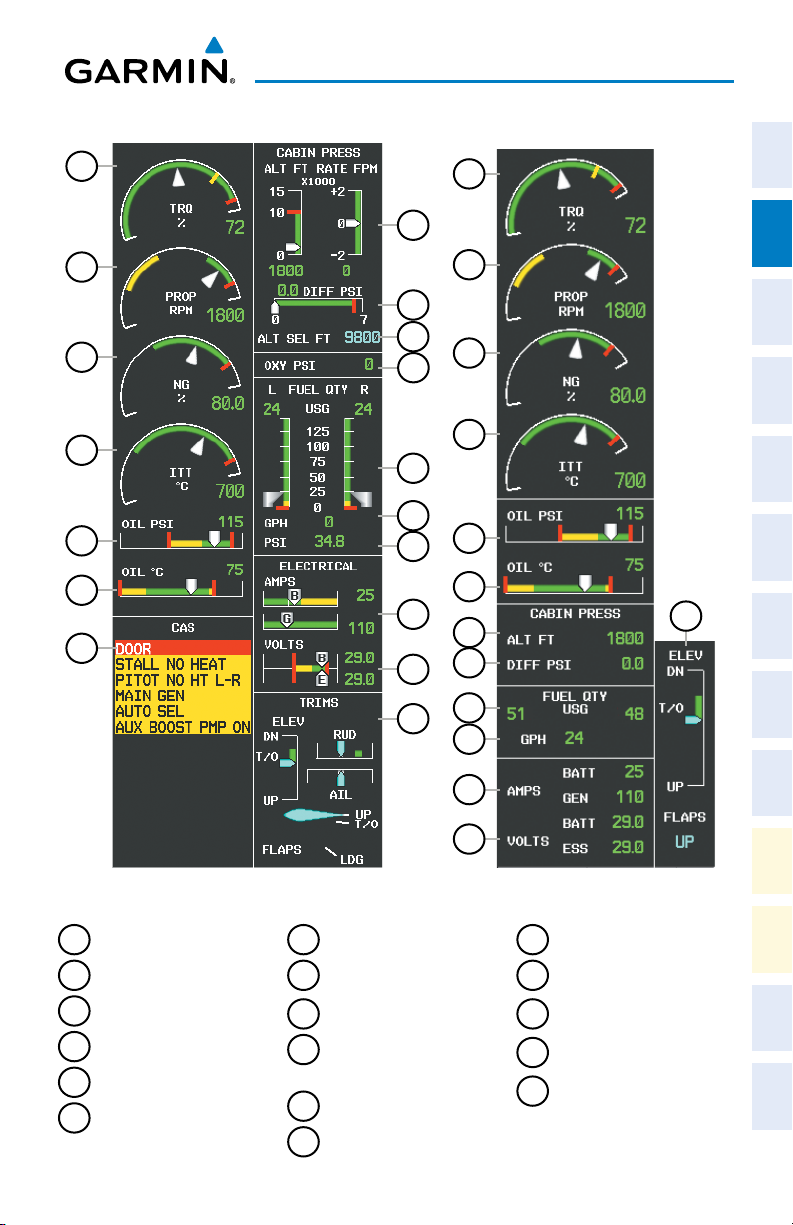
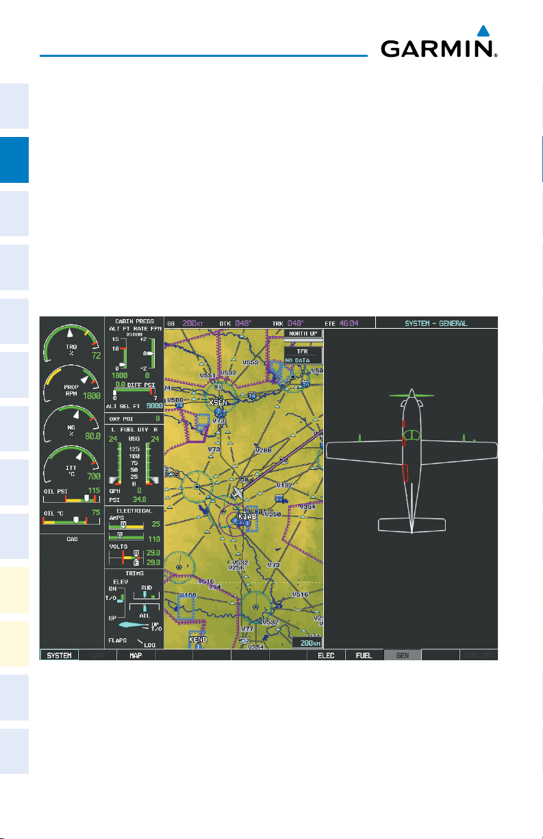
EIS Display (Normal Mode)
(TBM 850 shown)
1
Torque
2
Propeller Speed
7
CAS Display
8
Cabin Pressure Altitude and
Change Rate
3
Generator Speed
4
Interturbine Temperature
5
Oil Pressure
6
Oil Temperature
190-00708-05 Rev. C 5
Garmin G1000 Cockpit Reference Guide for the Socata TBM 850/900
9
Differential Pressure
10
Selected Cabin Altitude
(TBM850) or
LFE (TBM 900)
11
Oxygen Pressure
12
Fuel Quantity
EIS Display (Reversionary Mode)
(TBM 850 shown)
13
Fuel Flow
14
Fuel Pressure (if installed)
(TBM 850 only)
15
Battery and Generator
Currents
16
Battery and Essential Bus
Voltages
17
Elevator, Aileron, and
Rudder Trim and Flap
Position
Operation
Abnormal
Annun/
Alerts Appendix Index
Page 24
Engine & Airframe Systems
ELECTRICAL SYSTEM
Flight
InstrumentsEAS
Nav/Com/
XPDR/AudioAFCSGPS Nav
Flight
PlanningProcedures
Hazard
Avoidance
Features
Additional
Abnormal
Operation
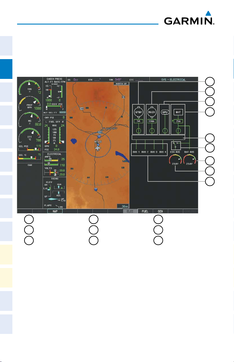
1)
Select the SYSTEM Softkey to display the softkeys for the synoptics system.
2)
Select the ELEC Softkey to display the Electrical System Page.
1
Standby Generator
2
Main Generator
3
Ground Power
4
Battery
5
Main Bus
6
Emergency Switch
7
Battery Bus
8
Essential Bus
9
Power Buses
Unit Door
Electrical Synoptics Page
1
2
3
4
5
6
7
8
9
AlertsAppendixIndex
Annun/
6
Garmin G1000 Cockpit Reference Guide for the Socata TBM 850/900
190-00708-05 Rev. C
Page 25
Engine & Airframe Systems
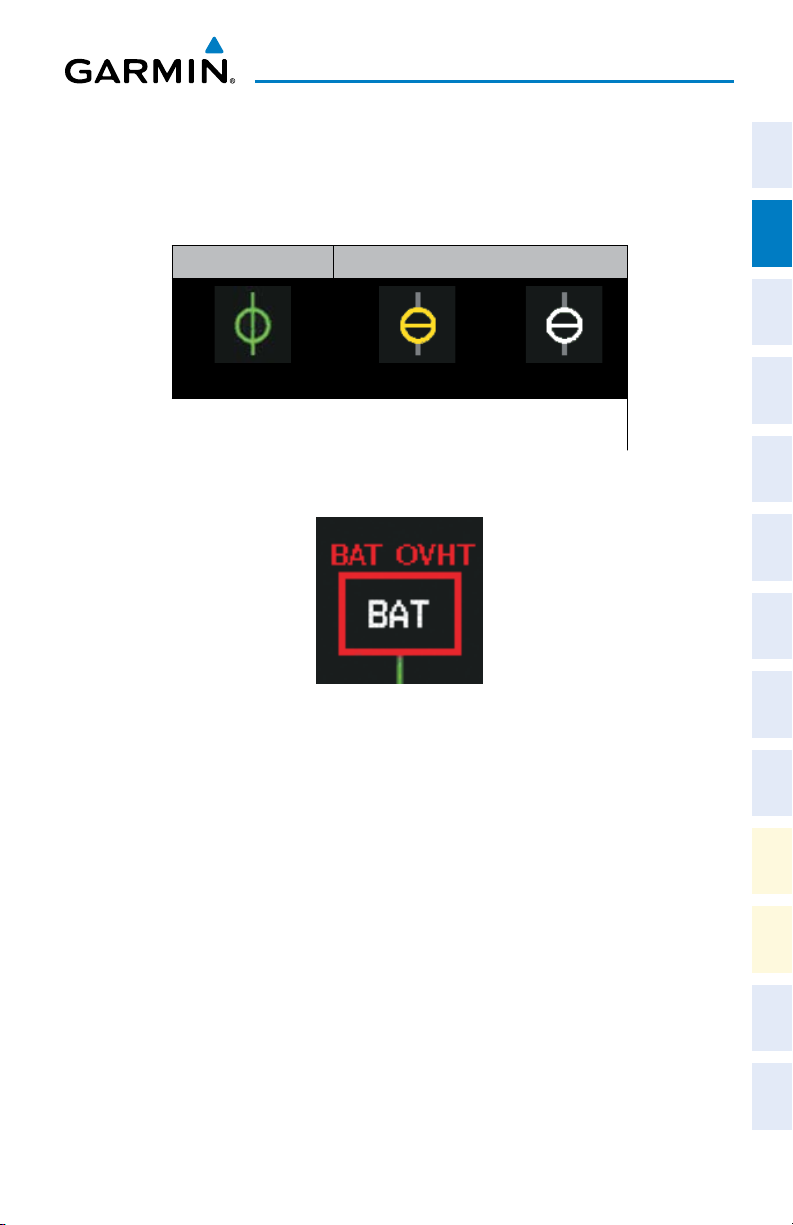
Battery connection status to the main bus is indicated in green; direction of
current flow is indicated with an arrow next to the current readout. If the battery is
disconnected from the main bus, the switch is closed. Battery overheating is indicated
in red with a ‘BAT OVHT’ annunciation; a CAS message is also generated.
Switch Open Switch Closed
Main
Generator Switch Status
Battery Overheat Indication
Standby
Instruments EAS
Flight
XPDR/Audio AFCS GPS Nav
Nav/Com/
Planning Procedures
Flight
Avoidance
Hazard
190-00708-05 Rev. C 7
Garmin G1000 Cockpit Reference Guide for the Socata TBM 850/900
Additional
Features
Operation
Abnormal
Annun/
Alerts Appendix Index
Page 26
Engine & Airframe Systems
FUEL SYSTEM
Flight
InstrumentsEAS
Nav/Com/
XPDR/AudioAFCSGPS Nav
Flight
PlanningProcedures
Hazard
Avoidance
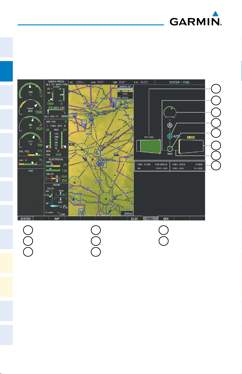
1)
Select the SYSTEM Softkey to display the softkeys for the synoptics system.
2)
Select the FUEL Softkey to display the Fuel System Page.
Left Fuel Tank
1
4
Auxiliary Boost Pump
7
Right Fuel Line
1
2
3
4
5
6
7
8
Features
Additional
Abnormal
Operation
AlertsAppendixIndex
Annun/
Left Fuel Line
2
3
Fuel Pressure (TBM
Fuel Selector
5
6
Right Fuel Tank
Fuel Flow Data
8
850 only)
Fuel Synoptics Page
8
Garmin G1000 Cockpit Reference Guide for the Socata TBM 850/900
190-00708-05 Rev. C
Page 27

Engine & Airframe Systems
Status of the fuel selector is indicated between the fuel tank symbols. The mode,
Instruments EAS
Flight
automatic (AUTO), manual (MAN), or off (no indication; CAS message ‘FUEL OFF’
generated) is shown beneath the fuel selector symbol.
Left Fuel
Tank
Selected
Switching
Fuel Tank
Selection
Right
Fuel Tank
Selected
Fuel Selector Status
Unknown Fuel
Tank Selection
Manual or
Fuel
Selector
Off
XPDR/Audio AFCS GPS Nav
Nav/Com/
If the auxiliary fuel boost pump is on, the symbol is displayed in green. The mode,
automatic (AUTO) or manual (MAN) is displayed next to the pump symbol. If the
Planning Procedures
Flight
boost pump is off, the symbol is shown in cyan (automatic mode) or red (manual
mode).
Fuel Boost Pump OnFuel Boost Pump
Off (Auto)
Fuel Boost Pump
Off (Manual)
Avoidance
Hazard
Auxiliary Boost Pump Status
190-00708-05 Rev. C 9
Garmin G1000 Cockpit Reference Guide for the Socata TBM 850/900
Additional
Features
Operation
Abnormal
Annun/
Alerts Appendix Index
Page 28
Engine & Airframe Systems
GENERAL SYSTEMS
Flight
InstrumentsEAS
1)
Select the SYSTEM Softkey to display the softkeys for the synoptics system.
2)
Select the GEN Softkey to display the Fuel System Page.
The General Synoptics Page aircraft diagram displays open doors in red (CAS
messages also generated). Statuses of propeller, stall sensor heater, pitot probe, and
windshield heat are also indicated on the diagram:
Nav/Com/
XPDR/AudioAFCSGPS Nav
• White indicates that heat is off (propeller and windshield)
• Cyan indicates heat has been selected (windshield)
• Green indicates heat is on
• Yellow indicates heat has failed (propeller, pitot tube, and stall sensor).
Flight
PlanningProcedures
Hazard
Avoidance
Features
Additional
Abnormal
Operation
AlertsAppendixIndex
Annun/
10
General Synoptics Page
Garmin G1000 Cockpit Reference Guide for the Socata TBM 850/900
190-00708-05 Rev. C
Page 29
Engine & Airframe Systems
CABIN PRESSURIZATION
Instruments EAS
Flight
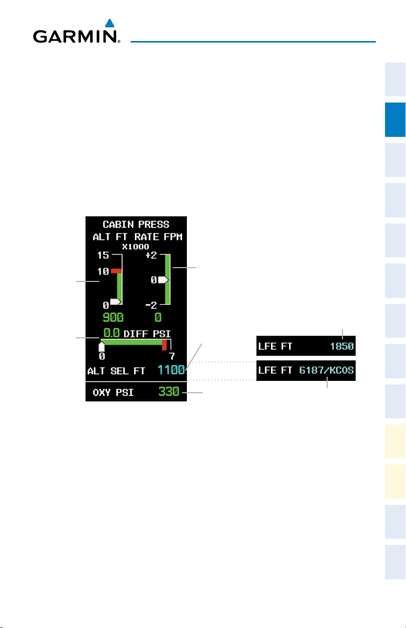
Cabin pressurization information (cabin altitude, rate of change, and differential
cabin pressure) is shown at the top of the right EIS column. Only readouts for cabin
altitude and pressure differential are displayed in Reversionary Mode.
Cabin altitude (ALT FT) is shown on a color-coded scale labeled in 5,000-ft
increments with a readout (in feet) below. Cabin altitude change rate (RATE FPM) is
XPDR/Audio AFCS GPS Nav
Nav/Com/
displayed on a scale in terms of 2,000 fpm increments with a readout (in fpm) below.
Cabin pressure differential (DIFF PSI), in pounds per square inch (psi), is indicated
on a color-coded scale with a readout. Selected Cabin Altitude is displayed as a digital
readout (in 100 ft increments) with a range from -1,000 to 11,000 feet.
Pressure
Altitude
Pressure
Differential
Pressure
Change
Rate
Selected
Cabin
Altitude
Landing Field
Elevation Entered
Manually
Planning Procedures
Flight
Avoidance
Hazard
Additional
Oxygen
Pressure
Landing Field Elevation
From Active Flight Plan
Features
Cabin Pressure Display
Operation
Abnormal
The pressure (in psi) for the oxygen system is given as a readout below the cabin
pressurization display under normal display conditions.
Annun/
LFE (Landing Field Elevation)(TBM 900 only)
Alerts Appendix Index
The Landing Field Elevation can be set based on the destination airport in the active
flight plan, or entered manually. When entered based on the active flight plan, the
elevation will be derived from the navigation database based on the destination airport.
System derived values appear with the destination airport identifier. Manually entered
values appear without the airport identifier. A red “X” is displayed if the LFE is out of
range or the data source is invalid.
190-00708-05 Rev. C 11
Garmin G1000 Cockpit Reference Guide for the Socata TBM 850/900
Page 30
Engine & Airframe Systems
Setting the displayed landing field elevation to the value for the
Flight
destination airport:
InstrumentsEAS
1)
Select the
2)
Select the
SYSTEM
FMS LFE
airport in the current flight plan.
Manually setting the displayed landing field elevation:
Softkey.
Softkey to set the LFE to the value for the destination
Nav/Com/
XPDR/AudioAFCSGPS Nav
Flight
PlanningProcedures
Hazard
Avoidance
Features
Additional
Abnormal
Operation
1)
Select the
2)
Select the MAN
3)
Use the ±250 and ±25 FT softkeys to set the desired elevation.
4)
To confirm the new LFE value, select the ACCEPT Softkey. If the ACCEPT
SYSTEM
LFE
Softkey.
Softkey.
Softkey is not selected, the value will flash briefly and return to the previous
setting.
AlertsAppendixIndex
Annun/
12
Garmin G1000 Cockpit Reference Guide for the Socata TBM 850/900
190-00708-05 Rev. C
Page 31

Nav/Com/XPDR/Audio Panel
NAV/COM/TRANSPONDER/AUDIO PANEL
ENTER OR CHANGE FLIGHT ID (OPTIONAL)
1)
Press the TMR/REF Softkey, then turn the large FMS Knob to highlight the
Flight ID field.
2)
Turn the small FMS Knob to enter the first character.
3)
Turn the large FMS Knob to select the next field.
4)
Turn the small FMS Knob to enter the next desired character.
5)
Repeat steps 3 and 4 until the desired Flight ID is entered.
6)
Press the ENT Key to update the Flight ID. Do not perform any other
G1000 functions until ‘updating’ is no longer displayed.
ADF TUNING (OPTIONAL)
1)
Press the ADF/DME Softkey.
2)
Turn the small FMS Knob to enter the first digit of the desired ADF
frequency.
3)
Turn the large FMS Knob to select the next desired field.
4)
Turn the small FMS Knob to enter the desired number.
5)
Repeat steps 3 and 4 until the desired ADF frequency is entered.
6)
Press the ENT Key to accept the new frequency.
7)
Press the ENT Key again to transfer the frequency to the active field.
8)
Turn the large FMS Knob to select the MODE field.
9)
Turn the small FMS Knob to select ANT, ADF, ADF/BFO, or ANT/BFO.
10)
Press the ENT Key to complete the selection.
Instruments EAS
Flight
XPDR/Audio AFCS GPS Nav
Nav/Com/
Planning Procedures
Flight
Avoidance
Hazard
Additional
Features
Operation
Abnormal
Annun/
Alerts Appendix Index
DME TUNING (OPTIONAL)
1)
Press the ADF/DME or DME Softkey.
2)
Turn the large FMS to select the DME source field.
3)
Turn the small FMS Knob to select the desired Nav radio.
4)
Press the ENT Key to complete the selection.
190-00708-05 Rev. C 13
Garmin G1000 Cockpit Reference Guide for the Socata TBM 850/900
Page 32

Nav/Com/XPDR/Audio Panel
ENTER A TRANSPONDER CODE
Flight
InstrumentsEAS
1)
Press the XPDR Softkey to display the transponder mode selection softkeys.
2)
If two transponders are available, press XPDR1 or XPDR2 to set the active
transponder. Otherwise, proceed to step 3.
3)
Press the CODE Softkey to display the transponder code selection softkeys,
for digit entry.
4)
Nav/Com/
XPDR/AudioAFCSGPS Nav
Use the digit keys to enter the code in the code field. When entering the
code, the next key in sequence must be pressed within 10 seconds, or the
entry is cancelled and restored to the previous code. Five seconds after the
fourth digit has been entered, the transponder code becomes active.
SELECTING A COM RADIO
Transmit/Receive
Flight
PlanningProcedures
Press the COM1 MIC
Receive Only
Press the COM1 or COM2 on the audio panel.
SELECTING A NAV RADIO
Hazard
Avoidance
1)
To begin navigating using a navigation radio, press the CDI Softkey on the
PFD to select VOR1/LOC1 (NAV1) or VOR2/LOC2 (NAV2).
Features
2)
Additional
Press the NAV1, NAV2, DME, or ADF Key on the audio panel to select or
deselect the navigation radio audio source. All radio keys can be selected
individually or together.
Abnormal
Operation
NAV/COM TUNING
or
COM2 MIC on the audio panel.
AlertsAppendixIndex
Annun/
14
1)
Press the small tuning knob to select the desired radio for tuning. A cyan
box highlights the radio frequency to be tuned.
2)
Turn the respective tuning knobs to enter the desired frequency into the
standby frequency field. The large knob enters MHz and the small knob
enters kHz.
3)
Press the Frequency Transfer Key to place the frequency into the active
frequency field.
Garmin G1000 Cockpit Reference Guide for the Socata TBM 850/900
190-00708-05 Rev. C
Page 33

Nav/Com/XPDR/Audio Panel
INTERCOM
Instruments EAS
Flight
Pressing the INTR COM Key on either Audio Panel selects and deselects the
intercom on both Audio Panels. The annunciator is lit when the intercom is active.
The intercom connects the pilot and copilot together. Either the pilot or copilot may
select or deselect the intercom.
The CABIN Key initiates two way communication between the pilot or copilot and
XPDR/Audio AFCS GPS Nav
Nav/Com/
the passengers in the cabin. The annunciator is lit when the cabin intercom is active
on either Audio Panel.
The MAN SQ Key allows either automatic or manual control of the intercom
squelch setting. Pressing the MAN SQ Key enables manual squelch control, indicated
by the MAN SQ annunciator.
During manual squelch operation, pressing the ICS Knob switches between volume
and squelch adjustment, lighting the associated annunciator beneath the knob. When
the MAN SQ annunciator is lit, the ICS Knob controls both volume and squelch.
Planning Procedures
When the MAN SQ annunciator is extinguished, the ICS Knob controls only volume.
Flight
CONTROLLER PILOT DATA LINK COMMUNICATIONS (OPTIONAL)
The CPDLC (Controller Pilot Data Link Communications) system provides data link
communication between the aircraft and an Air Traffic Control facility. Communication
is normally in the form of text message elements that resemble phraseology used in
Avoidance
Hazard
voice communications with ATC.
Generally, messages are closed with an acknowledgement or acceptance. When a
Additional
message is acknowledged, the connection with the ATC facility is not terminated, but
Features
kept active for future communication.
Communication hand-off to the next ATC facility is usually performed automatically,
Operation
but may also be accomplished manually by the pilot.
Abnormal
Connecting to the CPDLC System
Annun/
A flight plan must be filed prior to logging on to the CPDLC system. After entering
Alerts Appendix Index
flight plan information in the required fields and successfully logging on to the system,
messages may be sent and received.
The following parameters are used to log on to the system:
• Facility
• Flight ID
• Destination Airport
• Filed Departure Airport
• File Departure Time (Optional)
190-00708-05 Rev. C 15
Garmin G1000 Cockpit Reference Guide for the Socata TBM 850/900
Page 34

Nav/Com/XPDR/Audio Panel
Performing the system log-on:
Flight
InstrumentsEAS
Nav/Com/
XPDR/AudioAFCSGPS Nav
Flight
PlanningProcedures
Hazard
Avoidance
Features
Additional
Abnormal
Operation
1)
From the MFD, select the
CPDLC
Softkey. Ensure ‘Link Available’ is
displayed in the Status Box.
2)
Select the
3)
Turn the large
4)
Turn the small
LOGON
FMS
FMS
Softkey.
Knob to place the selection cursor over the Facility field.
Knob to select the desired ATC facility to which the
CPDLC connection will be established.
5)
Press the
6)
Turn the large
ENT
Key to complete the entry.
FMS
Knob to place the selection cursor over the Flight ID
field.
7)
Turn the small FMS Knob to enter the Flight ID or aircraft registration
number.
8)
Press the
9)
Turn the large
ENT
Key to complete the entry.
FMS
Knob to place the selection cursor over the Destination
Airport field.
10)
Enter the identifier of the destination airport used in the filed flight plan
and press the
11)
The Filed Departure Airport field is prefilled with the airport identifier
ENT
Key.
corresponding to the current aircraft location. If the flight plan was filed
using a different airport identifier, turn the large
FMS
Knob to place the
selection cursor over the Filed Departure Airport field, enter the departure
airport, and press the
12)
(Optional) Turn the large
ENT
FMS
Key.
Knob to place the selection cursor over the
Filed Departure Time field.
13)
(Optional) Enter the departure time used in the filed flight plan and press
the
ENT
Key.
AlertsAppendixIndex
Annun/
14)
Turn the large
16
FMS
Knob to place the selection cursor over SEND and
press the
ENT
Key. The Status immediately indicates ‘Connecting’. After
successful log-on, the Status indicates ‘Waiting For CPDLC’. Once a CPDLC
session is initiated by ATC, the Status indicates ‘Connected’ and the Current
Facility field is populated with the name of the facility. If a transfer to
another facility is needed, the Next Facility field is populated. Pressing the
LOGOFF
Softkey terminates the log-on process.
Garmin G1000 Cockpit Reference Guide for the Socata TBM 850/900
190-00708-05 Rev. C
Page 35

Nav/Com/XPDR/Audio Panel
Creating a Message
Creating a message consists of choosing from a pre-determined list of requests,
entering the required information, and sending the request.
To create messages:
1)
From the MFD, select the
2)
Select the
3)
With the Response/Request field highlighted, turn the small
NEW
Softkey. The CPDLC Thread Window appears.
to select the desired request from the list and press the
CPDLC
Softkey.
FMS
ENT
Knob
Key. For
discussion purposes, ‘Request [level]’ is selected.
4)
Highlight the Level field and enter the desired altitude. To toggle between
multiple units of measure (FT or FL), highlight the first numeric position and
turn the small
5)
Press the
6)
Highlight the Reason field and enter the desired reason from the list.
7)
Press the
8)
Highlight the SEND Button and press the
FMS
Knob counterclockwise.
ENT
Key to complete the entry.
ENT
Key to complete the entry.
ENT
Key.
Responding to an ATC Message
Responding to an ATC message consists of choosing from a pre-determined list
of responses or acknowledgements, then sending the response or acknowledgement.
To respond to a message:
Instruments EAS
Flight
XPDR/Audio AFCS GPS Nav
Nav/Com/
Planning Procedures
Flight
Avoidance
Hazard
Additional
Features
1)
From the MFD, select the
2)
Turn the large
FMS
message and press the
3)
Turn the small
list and press the
4)
Highlight the SEND Button and press the
190-00708-05 Rev. C 17
FMS
ENT
Garmin G1000 Cockpit Reference Guide for the Socata TBM 850/900
CPDLC
Softkey.
Knob to place the selection cursor over the desired
ENT
Key.
Knob to select the desired Response/Request from the
Key.
ENT
Key.
Operation
Abnormal
Annun/
Alerts Appendix Index
Page 36

Nav/Com/XPDR/Audio Panel
Viewing CPDLC Message Dialogs
Flight
The status of a string of messages, or dialog, may be checked and past message
InstrumentsEAS
dialogs viewed. When G1000 power is cycled, the list of message dialogs is deleted.
To view messages:
1)
Nav/Com/
XPDR/AudioAFCSGPS Nav
From the MFD, select the
2)
Turn the large
FMS
message to view and press the
3)
Press the
ENT
Key to view the CPDLC Thread.
CPDLC
Softkey.
Knob to place the selection cursor over the desired
ENT
Key.
Deleting Message Dialogs
While the G1000 deletes the list of message dialogs when power is turned off,
individual message dialogs may also be deleted manually. Message dialogs considered
closed may also be deleted.
Flight
To delete a single message dialog:
PlanningProcedures
1)
From the MFD, select the
2)
Turn the large
FMS
CPDLC
Knob to place the selection cursor over the desired
Softkey.
message to delete.
3)
Hazard
Avoidance
Select the
4)
Highlight OK and press the
DELETE
Softkey. A confirmation window appears.
ENT
Key.
To delete all closed message dialogs:
Features
Additional
Abnormal
Operation
1)
From the MFD, select the
2)
Select the
3)
Highlight OK and press the
DEL ALL
Softkey. A confirmation window appears.
Disconnecting from the CPDLC System
AlertsAppendixIndex
Annun/
After successfully initiating a CPDLC session, the LOGOFF Softkey becomes
available.
To Log-off the CPDLC System:
1)
From the MFD, select the
2)
Select the
18
LOGOFF
Garmin G1000 Cockpit Reference Guide for the Socata TBM 850/900
Softkey.
CPDLC
ENT
CPDLC
Softkey.
Key.
Softkey.
190-00708-05 Rev. C
Page 37

Nav/Com/XPDR/Audio Panel
Enabling/Disabling Data Mode
Instruments EAS
It may be desirable to disable Data Mode on the GDR 66 VHF Data Link Transceiver,
or conversely, to enable it.
To disable data mode on the GDR 66:
1)
From the MFD, select the CPDLC Softkey.
2)
Press the Menu Key to display the page menu.
3)
Turn the small FMS Knob to highlight ‘Disable Data Mode’ and press the
ENT Key.
XPDR/Audio AFCS GPS Nav
To enable data mode on the GDR 66:
1)
From the MFD, select the CPDLC Softkey.
2)
Press the Menu Key to display the page menu.
3)
Turn the small FMS Knob to highlight ‘Enable Data Mode’ and press the
Planning Procedures
ENT Key.
PASSENGER ADDRESS (PA) SYSTEM
A passenger address system is provided by pressing the PA Key to deliver messages
to the passengers. The message is heard by the other pilot on the headset only if the
Avoidance
INTR COM Key is enabled. PA messages are one way from the flight deck to the
passengers.
CLEARANCE RECORDER AND PLAYER
Features
Flight
Nav/Com/
Flight
Hazard
Additional
NOTE: Pressing the play key on the pilot’s Audio Panel plays recorded audio
to the Pilot. Pressing the play key on the Copilot’s Audio Panel plays recorded
audio to the Copilot.
Recorded COM audio is stored in separate memory blocks. Once 2.5 minutes
of recording time have been reached, the recorder begins recording over the stored
memory blocks, starting from the oldest block.
The PLAY Key controls the play function. The PLAY annunciator flashes to indicate
when play is in progress. The PLAY annunciator turns off after playback is finished.
190-00708-05 Rev. C 19
Garmin G1000 Cockpit Reference Guide for the Socata TBM 850/900
Operation
Abnormal
Annun/
Alerts Appendix Index
Page 38

Nav/Com/XPDR/Audio Panel
Pressing the PLAY Key once plays the latest recorded memory block and then
returns to normal operation. Pressing the PLAY Key again during play of a memory
Flight
InstrumentsEAS
block stops play. If a COM input signal is detected during play of a recorded memory
block, play is halted.
Pressing the PLAY Key twice within one-half second while audio is playing plays
the previous block of recorded audio. Each subsequent two presses of the PLAY Key
within one-half second backtracks through the recorded memory blocks to reach and
play any recorded block.
Nav/Com/
XPDR/AudioAFCSGPS Nav
Flight
PlanningProcedures
Hazard
Avoidance
Features
Additional
Abnormal
Operation
AlertsAppendixIndex
Annun/
20
Garmin G1000 Cockpit Reference Guide for the Socata TBM 850/900
190-00708-05 Rev. C
Page 39

AFCS
AUTOMATIC FLIGHT CONTROL SYSTEM
NOTE: If sensor information (other than attitude) required for a flight director
mode becomes invalid or unavailable, the flight director automatically reverts
to the default mode for that axis.
NOTE: If the attitude information required for the default flight director modes
becomes invalid or unavailable, the autopilot automatically disengages.
FLIGHT DIRECTOR ACTIVATION
An initial press of a key listed in the following table (when the flight director is not
active) activates the pilot-side flight director in the listed modes.
Instruments EAS
Flight
XPDR/Audio AFCS GPS Nav
Nav/Com/
Control Pressed
Modes Selected
Lateral Vertical
FD Key Roll Hold (default) ROL Pitch Hold (default) PIT
AP Key Roll Hold (default) ROL Pitch Hold (default) PIT
CWS Button Roll Hold (default) ROL Pitch Hold (default) PIT
GA Switch
Takeoff (on ground)
Go Around (in air)TOGA
Takeoff (on ground)
Go Around (in air)TOGA
ALT Key Roll Hold (default) ROL Altitude Hold ALT
VS Key Roll Hold (default) ROL Vertical Speed VS
VNV Key Roll Hold (default) ROL Vertical Path Tracking* VPTH
GPS
NAV Key Navigation**
VOR
Pitch Hold (default) PIT
LOC
BC Key Backcourse*** BC Pitch Hold (default) PIT
APR Key Approach**
GPS
VOR
LOC
Pitch Hold (default)
Glidepath
Glideslope
PIT
GP
GS
HDG Key Heading Select HDG Pitch Hold (default) PIT
*Valid VNV flight plan must be entered before VNV Key press activates flight director.
**The selected navigation receiver must have a valid VOR or LOC signal or active GPS course before
NAV
or
APR
Key press activates flight director.
***The selected navigation receiver must have a valid LOC signal before BC Key press activates flight
director.
Planning Procedures
Flight
Avoidance
Hazard
Additional
Features
Operation
Abnormal
Annun/
Alerts Appendix Index
190-00708-05 Rev. C 21
Garmin G1000 Cockpit Reference Guide for the Socata TBM 850/900
Page 40

AFCS
VERTICAL MODES
Flight
InstrumentsEAS
Vertical Mode Description Control Annunciation
Holds the current aircraft pitch attitude;
Pitch Hold
Selected Altitude
Nav/Com/
XPDR/AudioAFCSGPS Nav
Armed
Altitude Hold Holds the current Altitude Reference ALT Key ALT nnnnn fT
Vertical Speed
Flight Level Change,
IAS Hold
Flight
PlanningProcedures
Flight Level Change,
Mach Hold
VNAV
VNAV Target
Hazard
Avoidance
Altitude Armed
Glidepath
Features
Additional
Glideslope
Abnormal
Operation
Takeoff
AlertsAppendixIndex
Annun/
Go Around
* ALTS armed automatically when PIT, VS, FLC, or GA active, and under VPTH when Selected Altitude
is to be captured instead of VNAV Target Altitude
** ALTV armed automatically under VPTH when VNAV Target Altitude is to be captured instead of
Selected Altitude
may be used to climb/descend to the
(default) PIT
Selected Altitude
AFCS armed to capture the altitude
displayed in the Selected Altitude
window
Maintains the current aircraft vertical
speed; may be used to climb/descend
VS Key VS nnnn fpm
to the Selected Altitude
Maintains the current aircraft airspeed
(in KIAS or Mach Number) while the
aircraft is climbing/descending to the
FLC Key
Selected Altitude
Captures and tracks the VNAV flight
path
VNV
Key
AFCS armed to capture the altitude
displayed in the VNAV Target Altitude
** ALTV
window
Captures and tracks the SBAS glidepath
on approach
APR Key
Captures and tracks the ILS glideslope
on approach
Commands a preprogrammed constant
pitch attitude and wings level in
preparation for takeoff
Disengages the autopilot and
GA
Switch
commands a constant preprogrammed
pitch attitude and wings level
* ALTS
FLC nnn kT
FLC M .nnn
VPTH
GP
GS
TO
GA
22
Garmin G1000 Cockpit Reference Guide for the Socata TBM 850/900
190-00708-05 Rev. C
Page 41

AFCS
LATERAL MODES
Lateral Mode Description Control Annunciation
Holds current aircraft roll attitude
Roll Hold
Low Bank Limits maximum commanded roll angle
Heading Select Captures and tracks Selected Heading
Navigation, GPS
Arm/Capture/Track
Navigation, VOR
Enroute Arm/
Capture/Track
Navigation, LOC
Arm/Capture/Track
(No Glideslope)
Backcourse Arm/
Capture/Track
Approach, GPS
Arm/Capture/Track
Approach, VOR
Arm/Capture/Track
Approach, ILS Arm/
Capture/Track
(Glideslope Mode
automatically armed)
Takeoff
Go Around
* No annunciation appears in the AFCS Status Box. The low bank angle range is indicated in green
along the Roll Scale of the Attitude Indicator.
or rolls wings level, depending on
commanded bank angle
Captures and tracks selected navigation
source (GPS, VOR, LOC)
Captures and tracks a localizer signal
for backcourse approaches
Captures and tracks selected navigation
source (GPS, VOR, LOC)
Commands a constant preprogrammed
constant pitch attitude and wings level
in preparation for takeoff
Disengages autopilot and commands
a preprogrammed constant pitch
attitude and wings level
(default) ROL
BANK
Key
HDG
Key
*
HDG
GPS
NAV
VOR
Key
LOC
BC Key BC
GPS
VAPP
APR Key
LOC
TO
GA
Switch
GA
Instruments EAS
Flight
XPDR/Audio AFCS GPS Nav
Nav/Com/
Planning Procedures
Flight
Avoidance
Hazard
Additional
Features
Operation
Abnormal
Annun/
Alerts Appendix Index
190-00708-05 Rev. C 23
Garmin G1000 Cockpit Reference Guide for the Socata TBM 850/900
Page 42

Flight
InstrumentsEAS
Nav/Com/
XPDR/AudioAFCSGPS Nav
Flight
PlanningProcedures
AFCS
Blank Page
Hazard
Avoidance
Features
Additional
Abnormal
Operation
AlertsAppendixIndex
Annun/
24
Garmin G1000 Cockpit Reference Guide for the Socata TBM 850/900
190-00708-05 Rev. C
Page 43

GPS NAVIGATION
DIRECT-TO NAVIGATION
Direct-to Navigation using the MFD
1)
Press the Direct-to
2)
Enter the waypoint identifier.
3)
Press the ENT Key to confirm the identifier. The ‘Activate?’ field is
highlighted.
4)
If no altitude constraint or course is desired, press the ENT Key to activate.
To enter an altitude constraint, proceed to step 5.
5)
Turn the large FMS Knob to place the cursor over the ‘VNV’ altitude field.
6)
Enter the desired altitude.
7)
Press the ENT Key. If the waypoint entered is an airport, the option to
select MSL or AGL is now displayed. If the waypoint is not an airport,
proceed to step 9.
8)
Turn the small FMS Knob to select ‘MSL’ or ‘AGL’.
9)
Press the ENT Key. The cursor is now flashing in the VNV offset distance
field.
10)
Enter the desired offset distance before (-) the waypoint.
11)
Press the ENT Key. The ‘Activate?’ field is highlighted.
12)
Press the ENT Key to activate.
( )
Key on the MFD Control Unit.
GPS Navigation
Instruments EAS
Flight
XPDR/Audio AFCS GPS Nav
Nav/Com/
Planning Procedures
Flight
Avoidance
Hazard
Additional
Features
Direct-to Navigation using the PFD
1)
Press the Direct-to Key
2)
Turn the large FMS Knob to place the cursor in the desired selection field.
3)
Turn the small FMS Knob to begin selecting the desired identifier, location,
etc.
4)
Press the ENT Key.
5)
The cursor is now flashing on ‘ACTIVATE?’. If no altitude constraint or
course is desired, press the ENT Key to activate. To enter an altitude
constraint, proceed to step 6.
6)
Turn the large FMS Knob to place the cursor over the ‘ALT’ altitude field.
190-00708-05 Rev. C 25
Garmin G1000 Cockpit Reference Guide for the Socata TBM 850/900
( )
on the PFD or controller.
Operation
Abnormal
Annun/
Alerts Appendix Index
Page 44

GPS Navigation
7)
Turn the small FMS Knob to enter the desired altitude.
8)
Flight
InstrumentsEAS
Nav/Com/
XPDR/AudioAFCSGPS Nav
ACTIVATE A STORED FLIGHT PLAN
Flight
PlanningProcedures
Hazard
Avoidance
Features
Additional
Press the ENT Key. If the waypoint entered is an airport, the option to
select MSL or AGL is now displayed. If the waypoint is not an airport,
proceed to step 10.
9)
Turn the small FMS Knob to select ‘MSL’ or ‘AGL’.
10)
Press the ENT Key. The cursor is placed in the ‘OFFSET’ field.
11)
Turn the small FMS Knob to enter the desired target altitude offset from
the selected Direct-to.
12)
Press the ENT Key to highlight ‘Activate?’ or turn the large FMS Knob to
highlight the ‘CRS’ field.
13)
Turn the small FMS Knob to enter the desired course to the waypoint.
14)
Press the ENT Key to highlight ‘ACTIVATE?’.
15)
Press the ENT Key again to activate the Direct-to.
1)
Press the FPL Key and turn the small FMS Knob to display the Flight Plan
Catalog Page.
2)
Press the FMS Knob to activate the cursor.
3)
Turn the large FMS Knob to highlight the desired flight plan
4)
Select the ACTIVE Softkey. The confirmation window is now displayed.
5)
With ‘OK’ highlighted, press the ENT Key to activate the flight plan. To cancel
the flight plan activation, turn the large FMS Knob to highlight ‘CANCEL’ and
press the ENT Key.
ACTIVATE A FLIGHT PLAN LEG
Abnormal
Operation
1)
From the Active Flight Plan Page, press the FMS Knob to activate the cursor
AlertsAppendixIndex
Annun/
and turn the large FMS Knob to highlight the desired waypoint.
2)
Select the ACT LEG Softkey.
OR
Press the MENU Key, select the ‘Activate Leg’ option from the page menu
and press the ENT Key. This step must be used when activating a leg from
the PFD.
3)
With ‘Activate’ highlighted, press the ENT Key.
26
Garmin G1000 Cockpit Reference Guide for the Socata TBM 850/900
190-00708-05 Rev. C
Page 45

GPS Navigation
STOP NAVIGATING A FLIGHT PLAN
1)
Press the FPL Key to display the Active Flight Plan Page.
2)
Press the MENU Key to display the Page Menu Window.
3)
Turn the large FMS Knob to highlight ‘Delete Flight Plan’ and press the ENT
Key. With ‘OK’ highlighted, press the ENT Key to deactivate the flight plan.
This will not delete the stored flight plan, only the active flight plan.
Instruments EAS
Flight
XPDR/Audio AFCS GPS Nav
Nav/Com/
VERTICAL NAVIGATION (VNAV)
The navigation database only contains altitudes for procedures that call for “Cross
at” altitudes. If the procedure states “Expect to cross at,” the altitude is not in the
database. In this case the altitude may be entered manually.
Planning Procedures
Flight
Large White
Text
Large Cyan
Text
Small Cyan
Text
Small Cyan
Subdued Text
Avoidance
Hazard
Additional
Features
Small White Text
with Altitude
Restriction Bar
Cross AT or ABOVE 5,000 ft
Cross AT 2,300 ft
Cross AT or BELOW 3,000 ft
190-00708-05 Rev. C 27
Garmin G1000 Cockpit Reference Guide for the Socata TBM 850/900
Operation
Abnormal
Annun/
Alerts Appendix Index
Page 46

GPS Navigation
Since altitudes loaded with an arrival procedure are published only for turbojet
aircraft, the altitudes are displayed as white text indicating that the altitudes are
Flight
InstrumentsEAS
displayed for reference only. An arrival waypoint altitude may be used (or “designated”)
as is, or changed to a different altitude. An altitude is designated by pressing the FMS
Knob and turning the large FMS Knob to place the cursor on the desired altitude and
pressing the ENT Key or entering a different value and pressing the ENT Key. The
altitude is now displayed as blue text, indicating that the altitude is now designated to
give vertical speed and deviation guidance.
Nav/Com/
XPDR/AudioAFCSGPS Nav
Approach waypoint altitude constraints are designated in the same way as
previously described for arrivals. These altitudes are also displayed as blue text after
being designated for use. Waypoint altitude constraints may be designated up to, but
not including the FAF. The FAF is always a “reference only” altitude and cannot be
designated, unless the selected approach does not provide vertical guidance. In this
case, the FAF altitude can be designated.
Flight
PlanningProcedures
Hazard
Avoidance
Features
Additional
Abnormal
Operation
AlertsAppendixIndex
Annun/
Large Text
Small Text
White Text Cyan Text Cyan Subdued
Text
Altitude calculated by
the system estimating
the altitude of the
aircraft as it passes over
the navigation point.
This altitude is provided
as a reference and is
not designated to be
used in determining
vertical flight path
Altitude has been
entered by the pilot.
Altitude is designated
for use in giving vertical
flight path guidance.
Altitude does not match
the published altitude
in navigation database
or no published altitude
exists.
The system cannot
use this altitude
in determining
vertical flight path
guidance.
guidance.
Altitude is not
designated to be used
in determining vertical
flight path guidance.
Altitude has been
retrieved from the
navigation database
and is provided as a
reference.
Altitude is designated for
use in giving vertical flight
path guidance. Altitude
has been retrieved from
the navigation database
or has been entered by
the pilot and matches a
published altitude in the
navigation database.
The system cannot
use this altitude in
determining vertical
flight path guidance.
28
Garmin G1000 Cockpit Reference Guide for the Socata TBM 850/900
190-00708-05 Rev. C
Page 47

FLIGHT PLANNING
WEIGHT PLANNING
All procedures apply to the MFD unless otherwise stated.
Flight Planning
Instruments EAS
Flight
Entering Weight Parameters
The Weight Planning Page is displayed after system power-up. If it is necessary to
return to this page, turn the large
small
FMS
Knob to select the first rectangular page icon.
1)
Select the EMPTY WT Softkey to place the cursor in the Basic Empty
FMS
Knob to select the ‘AUX’ page group. Turn the
Weight field.
2)
Enter the desired aircraft empty weight.
3)
Press the ENT Key. The cursor is now over the ‘PILOT & STORES’ field.
4)
Enter the desired weight of Pilot & Stores.
5)
Press the ENT Key.
6)
Continue repeating these steps until all desired weights have been entered.
Entering Fuel Parameters
1)
If necessary, press the FMS Knob to activate the cursor.
2)
Turn the large FMS Knob to place the cursor in the ‘FUEL ON BOARD’ field.
3)
Select the FOB SYNC Softkey to enter the fuel on board quantity as read
from the aircraft fuel quantity sensors.
Or:
Manually enter the desired fuel quantity.
4)
Press the ENT Key. The cursor is now in the ‘FUEL RESERVES’ field.
5)
Enter the desired reserve fuel quantity.
6)
Press the FMS Knob to remove the cursor.
XPDR/Audio AFCS GPS Nav
Nav/Com/
Planning Procedures
Flight
Avoidance
Hazard
Additional
Features
Operation
Abnormal
Annun/
Alerts Appendix Index
TRIP PLANNING
1)
Turn the large FMS Knob to select the ‘AUX’ page group.
2)
Turn the small FMS Knob to select the second rectangular page icon.
3)
The current ‘PAGE MODE’ is displayed at the top of the page: ‘AUTOMATIC’
or ‘MANUAL’. To change the page mode, select the AUTO or MANUAL
Softkey.
190-00708-05 Rev. C 29
Garmin G1000 Cockpit Reference Guide for the Socata TBM 850/900
Page 48

Flight Planning
4)
For Direct-to planning:
Flight
InstrumentsEAS
Nav/Com/
XPDR/AudioAFCSGPS Nav
Flight
PlanningProcedures
Hazard
Avoidance
Features
Additional
Abnormal
Operation
AlertsAppendixIndex
Annun/
a)
b)
c)
d)
Or:
For point-to-point planning:
a)
b)
c)
d)
Or:
For flight plan leg planning:
a)
b)
c)
d)
Select the WPTS Softkey and verify that the starting waypoint field
indicates ‘P.POS’ (present position).
If necessary, press the MENU Key and select ‘Set WPT to Present
Position’ to display ‘P.POS’.
Press the ENT Key and the flashing cursor moves to the ending
waypoint field.
Enter the identifier of the ending waypoint and press the ENT Key to
accept the waypoint.
Enter the identifier of the starting waypoint.
Once the waypoint’s identifier is entered, press the ENT Key to accept
the waypoint. The flashing cursor moves to the ending waypoint.
Again, enter the identifier of the ending waypoint.
Press the ENT Key to accept the waypoint.
Select the FPL Softkey (at the bottom of the display).
Turn the small FMS Knob to select the desired flight plan (already
stored in memory), by number.
Turn the large FMS Knob to highlight the ‘LEG’ field.
Turn the small FMS Knob to select the desired leg of the flight plan, or
select ‘CUM’ to apply trip planning calculations to the entire flight plan.
Selecting ‘FPL 00’ displays the active flight plan. If an active flight plan
is selected, ‘REM’ will be an available option to display planning data
for the remainder of the flight plan.
NOTE: The page mode must be set to ‘MANUAL’ to perform the following
steps.
30
5)
Turn the large FMS Knob to highlight the departure time (DEP TIME) field.
NOTE: The departure time on the Trip Planning Page is used for preflight
planning. Refer to the Utility Page for the actual flight departure time.
Garmin G1000 Cockpit Reference Guide for the Socata TBM 850/900
190-00708-05 Rev. C
Page 49

Flight Planning
6)
Enter the departure time. Press the ENT Key when finished. Departure time
may be entered in local or UTC time, depending upon system settings.
7)
The flashing cursor moves to the ground speed (GS) field. Enter the ground
speed. Press the
ENT
Key when finished. Note that in ‘automatic’ page
mode, ground speed is provided by the system.
8)
The flashing cursor moves to the fuel flow field. Enter the fuel flow. Press
the ENT Key when finished. Note that in ‘AUTOMATIC’ page mode, fuel flow
is provided by the system.
9)
The flashing cursor moves to the fuel onboard field. Modify the fuel onboard.
Press the ENT Key when finished. In ‘AUTOMATIC’ mode, fuel onboard is
provided by the entry made on the Weight Planning Page.
10)
The flashing cursor moves to the calibrated airspeed (CALIBRATED AS) field.
Enter the calibrated airspeed. Press the ENT Key when finished. Note that
in ‘AUTOMATIC’ page mode, calibrated airspeed is provided by the system.
11)
The flashing cursor moves to the altitude (IND ALTITUDE) field. Enter the
altitude. Press the ENT Key when finished. Note that in ‘AUTOMATIC’ page
mode, altitude is provided by the system.
12)
The flashing cursor moves to the barometric setting (PRESSURE) field. Enter
the desired baro setting. Press the ENT Key when finished. Note that in
‘AUTOMATIC’ page mode, the baro setting is provided by the setting entered
on the PFD.
13)
The flashing cursor moves to the air temperature (TOTAL AIR TEMP) field. Enter
the desired air temperature. Press the ENT Key when finished. Note that in
‘AUTOMATIC’ page mode, air temperature is provided by the system outside
air temperature.
CREATE A USER WAYPOINT DEFINED BY LATITUDE & LONGITUDE
Instruments EAS
Flight
XPDR/Audio AFCS GPS Nav
Nav/Com/
Planning Procedures
Flight
Avoidance
Hazard
Additional
Features
Operation
Abnormal
1)
Turn the large FMS Knob on the MFD Control Unit to select the ‘WPT’ page
group.
2)
Turn the small FMS Knob to select the User WPT Information Page.
3)
Select the NEW Softkey. A waypoint is created at the current aircraft
position.
4)
Enter the desired waypoint name.
5)
Press the ENT Key.
190-00708-05 Rev. C 31
Garmin G1000 Cockpit Reference Guide for the Socata TBM 850/900
Alerts Appendix Index
Annun/
Page 50

Flight Planning
6)
The cursor is now in the ‘WAYPOINT TYPE’ field. If desired, the waypoint
Flight
InstrumentsEAS
can be made temporary (deleted automatically when the system is turned
off). If the waypoint is to remain in the system, proceed to step 7.
a)
Turn the large FMS Knob one click to the left to highlight
‘TEMPORARY’.
b)
Press the ENT Key to place a check-mark in the box. Turn the large
FMS Knob to place the cursor back in the ‘WAYPOINT TYPE’ field.
Nav/Com/
XPDR/AudioAFCSGPS Nav
7)
With the cursor in the ‘WAYPOINT TYPE’ field, turn the small FMS Knob to
display a list of waypoint types.
8)
Turn the small FMS Knob to select LAT/LON (latitude and longitude).
9)
Press the ENT Key.
CREATE A USER WAYPOINT DEFINED BY RADIALS FROM OTHER WAYPOINTS
1)
Turn the large FMS Knob on the MFD Control Unit to select the ‘WPT’ page
Flight
PlanningProcedures
Hazard
Avoidance
Features
Additional
Abnormal
Operation
AlertsAppendixIndex
Annun/
group.
2)
Turn the small FMS Knob to select the User WPT Information Page.
3)
Select the NEW Softkey. A waypoint is created at the current aircraft
position.
4)
Enter the desired waypoint name.
5)
Press the ENT Key.
6)
The cursor is now in the ‘WAYPOINT TYPE’ field. If desired, the waypoint
can be made temporary (deleted automatically when the system is turned
off). If the waypoint is to remain in the system, proceed to step 7.
a)
Turn the large FMS Knob one click to the left to highlight
‘TEMPORARY’.
b)
Press the ENT Key to place a check-mark in the box. Turn the large
FMS Knob to place the cursor back in the ‘WAYPOINT TYPE’ field.
7)
With the cursor in the ‘WAYPOINT TYPE’ field, turn the small FMS Knob to
display a list of waypoint types.
8)
Turn the small FMS Knob to select RAD/RAD (radial/radial).
9)
Press the ENT Key.
10)
The cursor moves to the ‘REFERENCE WAYPOINTS’ field. With the first
waypoint name highlighted, use the FMS Knobs to enter the desired
waypoint name. Waypoints may also be selected as follows:
32
Garmin G1000 Cockpit Reference Guide for the Socata TBM 850/900
190-00708-05 Rev. C
Page 51

Flight Planning
a)
When a flight plan is active, turning the small FMS Knob to the left will
display a list of the flight plan waypoints.
b)
Turn the large FMS Knob to select the desired waypoint.
c)
Press the ENT Key.
Or:
a)
Turn the small FMS Knob to the left. Initially, a flight plan waypoint list
is displayed.
b)
Turn the small FMS Knob to the right to display the ‘NRST’ airports to
the aircraft’s current position.
c)
Turn the large FMS Knob to select the desired waypoint.
d)
Press the ENT Key.
Or:
a)
Turn the small FMS Knob to the left. Initially, a flight plan waypoint list
is displayed.
b)
Turn the small FMS Knob to the right to display the ‘RECENT’
waypoints.
c)
Turn the large FMS Knob to select the desired waypoint.
d)
Press the ENT Key.
Or:
a)
Turn the small FMS Knob to the left. Initially, a flight plan waypoint list
is displayed.
b)
Turn the small FMS Knob to the right to display the ‘USER’ waypoints.
c)
Turn the large FMS Knob to select the desired waypoint.
d)
Press the ENT Key.
11)
Press the ENT Key. The cursor is displayed in the ‘RAD’ (radial) field. Enter
the desired radial from the reference waypoint.
12)
Press the ENT Key.
13)
Repeat step 10 to enter the next waypoint name.
14)
Press the ENT Key. The cursor is displayed in the ‘RAD’ (radial) field for the
second waypoint. Enter the desired radial from the reference waypoint.
15)
Press the ENT Key.
Instruments EAS
Flight
XPDR/Audio AFCS GPS Nav
Nav/Com/
Planning Procedures
Flight
Avoidance
Hazard
Additional
Features
Operation
Abnormal
Annun/
Alerts Appendix Index
16)
Press the FMS Knob to remove the flashing cursor.
190-00708-05 Rev. C 33
Garmin G1000 Cockpit Reference Guide for the Socata TBM 850/900
Page 52

Flight Planning
CREATE A USER WAYPOINT DEFINED BY A RADIAL & DISTANCE FROM
Flight
InstrumentsEAS
Nav/Com/
XPDR/AudioAFCSGPS Nav
Flight
PlanningProcedures
Hazard
Avoidance
Features
Additional
Abnormal
Operation
AlertsAppendixIndex
Annun/
ANOTHER WAYPOINT
1)
Turn the large FMS Knob on the MFD Control Unit to select the ‘WPT’ page
group.
2)
Turn the small FMS Knob to select the User WPT Information Page.
3)
Select the NEW Softkey. A waypoint is created at the current aircraft
position.
4)
Enter the desired waypoint name.
5)
Press the ENT Key.
6)
The cursor is now in the ‘WAYPOINT TYPE’ field. If desired, the waypoint
can be made temporary (deleted automatically when the system is turned
off). If the waypoint is to remain in the system, proceed to step 7.
a)
Turn the large FMS Knob one click to the left to highlight
‘TEMPORARY’.
b)
Press the ENT Key to place a check-mark in the box. Turn the large
FMS Knob to place the cursor back in the ‘WAYPOINT TYPE’ field.
7)
With the cursor in the ‘WAYPOINT TYPE’ field, turn the small FMS Knob to
display a list of waypoint types.
8)
Turn the small FMS Knob to select RAD/DIS (radial/distance).
9)
Press the ENT Key.
10)
The cursor moves to the ‘REFERENCE WAYPOINTS’ field. With the first
waypoint name highlighted, use the FMS Knobs to enter the desired
waypoint name. Waypoints may also be selected as follows:
a)
When a flight plan is active, turning the small FMS Knob to the left will
display a list of the flight plan waypoints.
b)
Turn the large FMS Knob to select the desired waypoint.
c)
Press the ENT Key.
Or:
a)
Turn the small FMS Knob to the left. Initially, a flight plan waypoint list
is displayed.
b)
Turn the small FMS Knob to the right to display the ‘NRST’ airports to
the aircraft’s current position.
c)
Turn the large FMS Knob to select the desired waypoint.
d)
Press the ENT Key.
34
Garmin G1000 Cockpit Reference Guide for the Socata TBM 850/900
190-00708-05 Rev. C
Page 53

Flight Planning
Or:
a)
Turn the small FMS Knob to the left. Initially, a flight plan waypoint list
is displayed.
b)
Turn the small FMS Knob to the right to display the ‘RECENT’
waypoints.
c)
Turn the large FMS Knob to select the desired waypoint.
d)
Press the ENT Key.
Or:
a)
Turn the small FMS Knob to the left. Initially, a flight plan waypoint list
is displayed.
b)
Turn the small FMS Knob to the right to display the ‘USER’ waypoints.
c)
Turn the large FMS Knob to select the desired waypoint.
d)
Press the ENT Key.
11)
Press the ENT Key. The cursor is displayed in the ‘RAD’ (radial) field. Enter
the desired radial from the reference waypoint.
12)
Press the ENT Key.
13)
The cursor is now displayed in the ‘DIS’ (distance) field. Enter the desired
distance from the reference waypoint.
14)
Press the ENT Key.
Instruments EAS
Flight
XPDR/Audio AFCS GPS Nav
Nav/Com/
Planning Procedures
Flight
Avoidance
Hazard
15)
Press the FMS Knob to remove the flashing cursor.
DELETE A USER WAYPOINT
1)
Turn the large FMS Knob to select the ‘WPT’ page group.
2)
Turn the small FMS Knob to select the User WPT Information Page.
3)
Press the FMS Knob to activate the cursor.
4)
Turn the large FMS Knob to the place the cursor in the ‘USER WAYPOINT LIST’
field.
5)
Turn the small FMS Knob to highlight the desired waypoint.
6)
Select the DELETE Softkey.
7)
The message ‘Would you like to delete the user waypoint?’ is displayed. With
‘YES’ highlighted, press the ENT Key.
190-00708-05 Rev. C 35
Garmin G1000 Cockpit Reference Guide for the Socata TBM 850/900
Additional
Features
Operation
Abnormal
Annun/
Alerts Appendix Index
Page 54

Flight Planning
CREATE A FLIGHT PLAN
Flight
InstrumentsEAS
Nav/Com/
XPDR/AudioAFCSGPS Nav
Flight
PlanningProcedures
Hazard
Avoidance
Features
Additional
Abnormal
Operation
AlertsAppendixIndex
Annun/
NOTE: When creating a flight plan in the Active Flight Plan Window, the first
leg is activated automatically after it is created.
Creating an active flight plan:
1)
Press the FPL Key.
2)
Press the FMS Knob to activate the cursor (only on MFD).
3)
Turn the small FMS Knob to display the Waypoint Information Window.
(Turning it clockwise displays a blank Waypoint Information Window,
turning it counter-clockwise displays the Waypoint Information Window
with a waypoint selection submenu allowing selection of active flight plan,
nearest, recent, user, or airway waypoints).
4)
Enter the identifier, facility, or city name of the departure waypoint or select
a waypoint from the submenu of waypoints and press the ENT Key. The
active flight plan is modified as each waypoint is entered.
5)
Repeat step numbers 3 and 4 to enter each additional flight plan waypoint.
6)
When all waypoints have been entered, press the FMS Knob to remove the
cursor.
Creating a stored flight plan:
1)
Press the FPL Key.
2)
Turn the small FMS Knob clockwise to display the Flight Plan Catalog Page.
3)
Select the NEW Softkey; or press the MENU Key, highlight ‘Create New
Flight Plan’, and press the ENT Key to display a blank flight plan for the
first empty storage location.
4)
Turn the small FMS Knob to display the Waypoint Information Window.
(Turning it clockwise displays a blank Waypoint Information Window,
turning it counter-clockwise displays the Waypoint Information Window
with a waypoint selection submenu allowing selection of active flight plan,
nearest, recent, user, or airway waypoints).
5)
Enter the identifier, facility, or city name of the departure waypoint or select
a waypoint from the submenu of waypoints and press the ENT Key.
6)
Repeat step numbers 4 and 5 to enter each additional flight plan waypoint.
7)
When all waypoints have been entered, press the FMS Knob to return to
the Flight Plan Catalog Page. The new flight plan is now in the list.
36
Garmin G1000 Cockpit Reference Guide for the Socata TBM 850/900
190-00708-05 Rev. C
Page 55

Flight Planning
IMPORT A FLIGHT PLAN FROM AN SD CARD
1)
Insert the SD card containing the flight plan in the top card slot on the MFD.
2)
Press the FPL Key on the MFD Control Unit to display the Active Flight Plan
Page on the MFD.
3)
Turn the small FMS Knob to select the Flight Plan Catalog Page.
4)
Press the FMS Knob to activate the cursor.
5)
Turn either FMS Knob to highlight an empty or existing flight plan.
6)
Select the IMPORT Softkey.
If an empty flight plan is selected, a list of the available flight plans on
the SD card will be displayed.
Or:
If an existing flight plan is selected, an ‘Overwrite existing flight plan?
OK or CANCEL’ prompt is displayed. Press the ENT Key to choose to
overwrite the selected flight plan and see a list of the available flight
plans on the SD card. If overwriting the existing flight plan is not
desired, select ‘CANCEL’ using the FMS Knob, press the ENT Key, select
another existing or empty flight plan, and again select the IMPORT
Softkey.
7)
Turn the small FMS Knob to highlight the desired flight plan for importing.
8)
Press the ENT Key.
INSERT A WAYPOINT IN THE ACTIVE FLIGHT PLAN
Instruments EAS
Flight
XPDR/Audio AFCS GPS Nav
Nav/Com/
Planning Procedures
Flight
Avoidance
Hazard
Additional
Features
1)
Press the FPL Key to display the active flight plan.
2)
If necessary, press the FMS Knob to activate the cursor.
3)
Turn the large FMS Knob to highlight the desired flight plan waypoint. The
new waypoint is inserted before the highlighted waypoint.
4)
Turn the small FMS Knob. The Waypoint Information Window is now
displayed.
5)
Enter the new flight plan waypoint by one of the following:
a)
Enter the user waypoint identifier, facility, or city.
b)
Press the ENT Key.
Or:
190-00708-05 Rev. C 37
Garmin G1000 Cockpit Reference Guide for the Socata TBM 850/900
Operation
Abnormal
Annun/
Alerts Appendix Index
Page 56

Flight Planning
a)
Flight
InstrumentsEAS
Nav/Com/
XPDR/AudioAFCSGPS Nav
Flight
PlanningProcedures
Hazard
Avoidance
6)
b)
c)
d)
a)
b)
c)
d)
a)
b)
c)
d)
Press the
Turn the small FMS Knob to the left. Initially, a flight plan waypoint list
is displayed.
Turn the small FMS Knob to the right to display the ‘NRST’ airport
waypoints to the aircraft’s current position.
Turn the large FMS Knob to select the desired waypoint.
Press the ENT Key.
Or:
Turn the small FMS Knob to the left. Initially, a flight plan waypoint list
is displayed.
Turn the small FMS Knob to the right to display the ‘RECENT’
waypoints.
Turn the large FMS Knob to select the desired waypoint.
Press the ENT Key.
Or:
Turn the small FMS Knob to the left. Initially, a flight plan waypoint list
is displayed.
Turn the small FMS Knob to the right to display the ‘USER’ waypoints.
Turn the large FMS Knob to select the desired user waypoint.
Press the ENT Key.
ENT
Key again to “accept” the waypoint.
ENTER AN AIRWAY IN A FLIGHT PLAN
Features
Additional
1)
Press the FPL Key.
2)
Abnormal
Operation
AlertsAppendixIndex
Annun/
38
Press the FMS Knob to activate the cursor (not required on the PFD).
3)
Turn the large FMS Knob to highlight the waypoint field after the desired
airway entry point. If this previous waypoint is not a valid airway entry
point, a valid entry point should be entered at this time.
4)
Turn the small FMS Knob one click clockwise and select the LD AIRWY
Softkey, or press the MENU Key and select “Load Airway”. The Select
Airway Page is displayed. The LD AIRWY Softkey or the “Load Airway”
menu item is available only when an acceptable airway entry waypoint has
been chosen (the waypoint ahead of the cursor position).
Garmin G1000 Cockpit Reference Guide for the Socata TBM 850/900
190-00708-05 Rev. C
Page 57

Flight Planning
5)
Turn the FMS Knob to select the desired airway from the list, and press the
ENT Key. Low altitude airways are shown first in the list, followed by “all”
altitude airways, and then high altitude airways.
6)
Turn the FMS Knob to select the desired airway exit point from the list, and
press the ENT Key. ‘LOAD?’ is highlighted.
7)
Press the ENT Key. The system returns to editing the flight plan with the
new airway inserted.
CREATING A USER-DEFINED HOLD AT AN ACTIVE FLIGHT PLAN WAYPOINT
1)
Press the FPL Key to display the Active Flight Plan Page (MFD) or the Active
Flight Plan Window (PFD).
2)
Press the FMS Knob to activate the cursor (not required on the PFD) and
turn the large FMS Knob to highlight the waypoint for the hold.
3)
Press the MENU Key, highlight ‘Hold At Wpt’, and press the ENT Key. The
HOLD AT window appears with the course field highlighted.
4)
Use the FMS Knobs to edit the entry course, and press the ENT Key.
5)
Use the small FMS Knob to select ‘INBOUND’ or ‘OUTBOUND’ course
direction, and press the ENT Key.
6)
Use the small FMS Knob to select ‘TIME’ or ‘DIST’ length mode, and press
the ENT Key.
7)
Use the FMS Knobs to edit the length, and press the ENT Key.
8)
Use the small FMS Knob to select ‘RIGHT’ or ‘LEFT’ turn direction, and
press the ENT Key.
9)
Use the FMS Knobs to edit the Expect Further Clearance Time (EFC TIME),
and press the ENT Key.
10)
Press the ENT Key while ‘LOAD?’ is highlighted to add the hold into the
flight plan.
CREATING A USER-DEFINED HOLD AT THE AIRCRAFT PRESENT POSITION
Instruments EAS
Flight
XPDR/Audio AFCS GPS Nav
Nav/Com/
Planning Procedures
Flight
Avoidance
Hazard
Additional
Features
Operation
Abnormal
Annun/
Alerts Appendix Index
1)
Press the FPL Key to display the Active Flight Plan Page (MFD) or the Active
Flight Plan Window (PFD).
2)
Press the MENU Key, highlight ‘Hold At Present Position’, and press the
ENT Key. The HOLD AT window appears with the Length mode highlighted.
3)
Use the small FMS Knob to select ‘TIME’ or ‘DIST’ length mode, and press
the ENT Key.
190-00708-05 Rev. C 39
Garmin G1000 Cockpit Reference Guide for the Socata TBM 850/900
Page 58

Flight Planning
4)
Use the FMS Knobs to edit the length, and press the ENT Key.
5)
Flight
InstrumentsEAS
Nav/Com/
XPDR/AudioAFCSGPS Nav
REMOVING A USER-DEFINED HOLD (CREATED AT THE AIRCRAFT P.POS)
Flight
PlanningProcedures
Use the small FMS Knob to select ‘RIGHT’ or ‘LEFT’ turn direction, and
press the ENT Key.
6)
Use the FMS Knobs to edit the Expect Further Clearance Time (EFC TIME),
and press the ENT Key.
7)
Press the ENT Key while ‘ACTIVATE?’ is highlighted to immediately activate
the hold.
1)
Press the FPL Key to display the Active Flight Plan Page (MFD) or the Active
Flight Plan Window (PFD).
2)
Press the FMS Knob to activate the cursor (not required on the PFD) and
turn the large FMS Knob to highlight the PPOS-H waypoint.
3)
Press the CLR Key. A “Remove Holding Pattern?” confirmation window is
displayed.
4)
Select ‘OK’ and press the ENT Key. The holding pattern is removed from
the active flight plan. Select ‘CANCEL’ and press the ENT Key to cancel the
removal of the holding pattern.
REMOVING A USER-DEFINED HOLD (CREATED AT AN ACTIVE WAYPOINT)
1)
Hazard
Avoidance
Features
Additional
Press the FPL Key to display the Active Flight Plan Page (MFD) or the Active
Flight Plan Window (PFD).
2)
Press the FMS Knob to activate the cursor (not required on the PFD) and
turn the large FMS Knob to highlight the HOLD waypoint.
3)
Press the CLR Key. A ‘Remove Holding Pattern?’ confirmation window is
displayed.
Abnormal
Operation
4)
Select ‘OK’ and press the ENT Key. The holding pattern is removed from
the active flight plan. Select ‘CANCEL’ and press the ENT Key to cancel the
AlertsAppendixIndex
Annun/
removal of the holding pattern.
INVERT AN ACTIVE FLIGHT PLAN
1)
Press the FPL Key to display the active flight plan.
2)
Press the MENU Key to display the Page Menu.
3)
Turn the large FMS Knob to highlight ‘Invert Flight Plan’.
40
Garmin G1000 Cockpit Reference Guide for the Socata TBM 850/900
190-00708-05 Rev. C
Page 59

Flight Planning
4)
Press the ENT Key. The original flight plan remains intact in its flight plan
catalog storage location.
5)
With ‘OK’ highlighted, press the ENT Key to invert the flight plan.
REMOVE A DEPARTURE, ARRIVAL, APPROACH, OR AIRWAY FROM A FLIGHT
PLAN
1)
Press the FPL Key to display the active flight plan. Press the FMS Knob to
activate the cursor.
Or, for a stored flight plan:
a)
Press the MFD FPL Key and turn the small FMS Knob to select the
Flight Plan Catalog Page.
b)
Press the FMS Knob to activate the cursor.
c)
Turn the large FMS Knob to highlight the desired flight plan.
d)
Select the EDIT Softkey.
2)
Turn the large FMS Knob to highlight the title for the approach, departure,
arrival, or airway to be deleted. Titles appear in white directly above the
procedure’s waypoints.
3)
Press the CLR Key to display a confirmation window.
4)
With ‘OK’ highlighted, press the ENT Key to remove the selected procedure
or airway.
Instruments EAS
Flight
XPDR/Audio AFCS GPS Nav
Nav/Com/
Planning Procedures
Flight
Avoidance
Hazard
STORE A FLIGHT PLAN
1)
After creating a flight plan on either the PFD or MFD, it may be saved by
pressing the MENU Key.
2)
Turn the large FMS Knob to highlight ‘Store Flight Plan’ and press the ENT Key.
3)
With ‘OK’ highlighted, press the ENT Key to store the flight plan.
EDIT A STORED FLIGHT PLAN
1)
Press the FPL Key for the MFD and turn the small FMS Knob to display the
Flight Plan Catalog Page.
2)
Press the FMS Knob to activate the cursor.
3)
Turn the large FMS Knob to highlight the desired flight plan.
4)
Select the EDIT Softkey.
190-00708-05 Rev. C 41
Garmin G1000 Cockpit Reference Guide for the Socata TBM 850/900
Additional
Features
Operation
Abnormal
Annun/
Alerts Appendix Index
Page 60

Flight Planning
5)
Turn the large FMS Knob to place the cursor in the desired location.
6)
Flight
InstrumentsEAS
Enter the changes, then press the ENT Key.
7)
Press the FMS Knob to return to the Flight Plan Catalog Page.
DELETE A WAYPOINT FROM THE FLIGHT PLAN
1)
Press the FPL Key to display the active flight plan. Press the FMS Knob to
Nav/Com/
XPDR/AudioAFCSGPS Nav
Flight
PlanningProcedures
Hazard
Avoidance
activate the cursor.
Or, for a stored flight plan:
a)
Press the FPL Key of the MFD and turn the small FMS Knob to select
the Flight Plan Catalog Page.
b)
Press the FMS Knob to activate the cursor.
c)
Turn the large FMS Knob to highlight the desired flight plan.
d)
Select the EDIT Softkey.
2)
Turn the large FMS Knob to highlight the waypoint to be deleted.
3)
Press the CLR Key to display a ‘REMOVE (Wpt Name)?’ confirmation
window.
4)
With ‘OK’ highlighted, press the ENT Key to remove the waypoint. To cancel
the delete request, turn the large FMS Knob to highlight ‘CANCEL’ and press
the ENT Key.
5)
Once all changes have been made, press the FMS Knob to remove the
cursor.
INVERT AND ACTIVATE A STORED FLIGHT PLAN
Features
Additional
1)
Press the FPL Key for the MFD.
2)
Abnormal
Operation
AlertsAppendixIndex
Annun/
Turn the small FMS Knob to select the Flight Plan Catalog Page.
3)
Press the FMS Knob to activate the cursor.
4)
Turn the large FMS Knob to highlight the desired flight plan.
5)
Select the INVERT Softkey. ‘Invert and activate stored flight plan?’ is
displayed.
6)
With ‘OK’ highlighted, press the ENT Key. The selected flight plan is now
inverted and activated. The original flight plan remains intact in its flight plan
catalog storage location.
42
Garmin G1000 Cockpit Reference Guide for the Socata TBM 850/900
190-00708-05 Rev. C
Page 61

Flight Planning
COPY A FLIGHT PLAN
1)
Press the FPL Key for the MFD.
2)
Turn the small FMS Knob to select the Flight Plan Catalog Page.
3)
Press the FMS Knob to activate the cursor.
4)
Turn the large FMS Knob to highlight the flight plan to be copied.
5)
Select the COPY Softkey. A ‘Copy to flight plan #?’ confirmation window is
displayed.
6)
With ‘OK’ highlighted, press the ENT Key to copy the flight plan. To cancel,
turn the large FMS Knob to highlight ‘CANCEL’ and press the ENT Key.
DELETE A FLIGHT PLAN
1)
Press the FPL Key for the MFD.
2)
Turn the small FMS Knob to select the Flight Plan Catalog Page.
3)
Press the FMS Knob to activate the cursor.
4)
Turn the large FMS Knob to highlight the flight plan to be deleted.
5)
Select the DELETE Softkey. A ‘Delete flight plan #?’ confirmation window is
displayed.
6)
With ‘OK’ highlighted, press the ENT Key to delete the flight plan. To cancel,
turn the large FMS Knob to highlight ‘CANCEL’ and press the ENT Key.
Instruments EAS
Flight
XPDR/Audio AFCS GPS Nav
Nav/Com/
Planning Procedures
Flight
Avoidance
Hazard
GRAPHICAL FLIGHT PLAN CREATION
1)
Press the FPL Key to display the Active Flight Plan Page on the MFD.
2)
Press the Joystick to activate the map pointer. Use the Joystick to move
the pointer to the desired point on the map to be inserted as a waypoint in
the flight plan.
3)
The default insertion point is at the end of the flight plan. If the selected
waypoint is to be placed anywhere other than the end of the flight plan,
press the FMS Knob to activate the cursor. Waypoints are inserted
the cursor. Turn the large FMS Knob to select the desired insertion point.
4)
Select the LD WPT Softkey. The selected waypoint is inserted at the selected
point. The default user waypoint naming is USR000, USR001, USR002, and
so on.
5)
To change the user waypoint name, follow the procedure for modifying a user
waypoint.
190-00708-05 Rev. C 43
Garmin G1000 Cockpit Reference Guide for the Socata TBM 850/900
ABOVE
Additional
Features
Operation
Abnormal
Annun/
Alerts Appendix Index
Page 62

Flight Planning
EXPORT A FLIGHT PLAN TO AN SD CARD
1)
Flight
InstrumentsEAS
Nav/Com/
XPDR/AudioAFCSGPS Nav
Flight
PlanningProcedures
Insert the SD card into the top card slot on the MFD.
2)
Press the FPL Key on the MFD Control Unit to display the Active Flight Plan
Page on the MFD.
3)
Turn the small FMS Knob to select the Flight Plan Catalog Page.
4)
Press the FMS Knob to activate the cursor.
5)
Turn the large FMS Knob to highlight the flight plan to be exported.
6)
Select the EXPORT Softkey.
7)
Press the ENT Key to confirm the export.
Hazard
Avoidance
Features
Additional
Abnormal
Operation
AlertsAppendixIndex
Annun/
44
Garmin G1000 Cockpit Reference Guide for the Socata TBM 850/900
190-00708-05 Rev. C
Page 63

PROCEDURES
LOAD AND ACTIVATE A DEPARTURE PROCEDURE
1)
Press the PROC Key.
2)
Turn the large FMS Knob to highlight ‘SELECT DEPARTURE’.
3)
Press the ENT Key. The cursor is displayed in the ‘DEPARTURE’ field with a
list of available departures.
4)
Turn the large FMS Knob to highlight the desired departure.
5)
Press the ENT Key. A list of runways may be displayed for the departure. If
so, turn either FMS Knob to select the desired runway.
6)
Press the ENT Key. The cursor is displayed in the ‘TRANSITION’ field with a
list of available transitions.
7)
Turn the large FMS Knob to highlight the desired transition.
8)
Press the ENT Key.
9)
With ‘LOAD?’ highlighted, press the ENT Key. The departure is active when
the flight plan is active.
Procedures
Instruments EAS
Flight
XPDR/Audio AFCS GPS Nav
Nav/Com/
Planning Procedures
Flight
ACTIVATE A DEPARTURE LEG
1)
Press the FPL Key for the MFD to display the active flight plan.
2)
Press the FMS Knob to activate the cursor.
3)
Turn the large FMS Knob to highlight the TO waypoint of the desired leg
within the departure.
4)
Select the ACT LEG Softkey. A confirmation window showing the selected
leg is displayed.
5)
With ‘ACTIVATE’ highlighted, press the ENT Key.
LOAD AN ARRIVAL PROCEDURE
1)
Press the PROC Key.
2)
Turn the large FMS Knob to highlight ‘SELECT ARRIVAL’.
3)
Press the ENT Key. The cursor is displayed in the ‘ARRIVAL’ field with a list
of available arrivals.
190-00708-05 Rev. C 45
Garmin G1000 Cockpit Reference Guide for the Socata TBM 850/900
Avoidance
Hazard
Additional
Features
Operation
Abnormal
Annun/
Alerts Appendix Index
Page 64
Procedures
4)
Turn the large FMS Knob to highlight the desired arrival.
5)
Flight
InstrumentsEAS
Press the ENT Key. A list of transitions is displayed for the selected arrival.
6)
Turn either FMS Knob to select the desired transition.
7)
Press the ENT Key. A list of runways may be displayed for the selected
arrival.
8)
Turn the large FMS Knob to highlight the desired runway.
9)
Nav/Com/
XPDR/AudioAFCSGPS Nav
Press the ENT Key.
10)
With ‘LOAD?’ highlighted, press the ENT Key.
11)
The arrival becomes part of the active flight plan.
ACTIVATE AN ARRIVAL LEG
1)
Press the FPL Key to display the active flight plan.
2)
Press the FMS Knob to activate the cursor.
3)
Flight
PlanningProcedures
Turn the large FMS Knob to highlight the TO waypoint of the desired leg
within the arrival.
4)
Select the ACT LEG Softkey. A confirmation window showing the selected
leg is displayed.
5)
With ‘ACTIVATE’ highlighted, press the ENT Key.
Hazard
Avoidance
LOAD AND/OR ACTIVATE AN APPROACH PROCEDURE
Features
Additional
NOTE: If certain GPS parameters (SBAS, RAIM, etc.) are not available, some
published approach procedures for the desired airport may not be displayed
in the list of available approaches.
Abnormal
Annun/
Operation
AlertsAppendixIndex
1)
Press the PROC Key.
2)
Turn the large FMS Knob to highlight ‘SELECT APPROACH’.
3)
Press the ENT Key. A list of available approaches for the destination airport
is displayed.
4)
Turn either FMS Knob to highlight the desired approach.
5)
Press the ENT Key. A list of available transitions for the selected approach
procedure is now displayed.
6)
Turn either FMS Knob to select the desired transition. The “Vectors”
option assumes vectors will be received to the final course segment of
46
Garmin G1000 Cockpit Reference Guide for the Socata TBM 850/900
190-00708-05 Rev. C
Page 65

Procedures
the approach and will provide navigation guidance relative to the final
approach course.
7)
Press the ENT Key. The cursor moves to the MINIMUMS field.
8)
If desired, the DA/MDA for the selected approach procedure may be
entered and displayed on the PFD. Turn the small
FMS
Knob in the
direction of the green arrow to change the display from OFF to BARO,
optional RAD ALT, or TEMP COMP.
9)
Press the
FMS
ENT
Key. The cursor moves to the altitude field. Turn the small
Knob to enter the published DA/MDA for the selected approach
procedure.
10)
Press the
ENT
Key. If BARO, RAD ALT, or OFF was selected step 8, proceed
to step 11. If TEMP COMP was selected in step 8, the cursor moves to the
‘TEMP AT....” field. Turn the small
FMS
Knob to enter the temperature at
the destination airport. The temperature compensated altitude minimum is
displayed below the previously enter minimum altitude value.
11)
Press the ENT Key. ‘LOAD? or ACTIVATE?’ is now displayed with ‘LOAD?’
highlighted.
12)
Turn the large FMS Knob to select either ‘LOAD?’ or ‘ACTIVATE?’.
Selecting ‘LOAD?’ enters the selected approach procedure into the active
flight plan, but is not currently active. Selecting ‘ACTIVATE?’ enters the
selected approach procedure into the active flight plan and activates the
first leg of the approach.
13)
Press the ENT Key.
Instruments EAS
Flight
XPDR/Audio AFCS GPS Nav
Nav/Com/
Planning Procedures
Flight
Avoidance
Hazard
Additional
Features
ACTIVATE AN APPROACH IN THE ACTIVE FLIGHT PLAN
1)
Press the PROC Key.
2)
Turn the large FMS Knob to highlight ‘ACTIVATE APPROACH’.
3)
Press the ENT Key.
ACTIVATE A VECTOR TO FINAL APPROACH FIX
1)
Press the PROC Key.
2)
Turn the large FMS Knob to highlight ‘ACTIVATE VECTOR-TO-FINAL’.
3)
Press the ENT Key.
4)
The final approach course becomes the active leg.
190-00708-05 Rev. C 47
Garmin G1000 Cockpit Reference Guide for the Socata TBM 850/900
Operation
Abnormal
Annun/
Alerts Appendix Index
Page 66
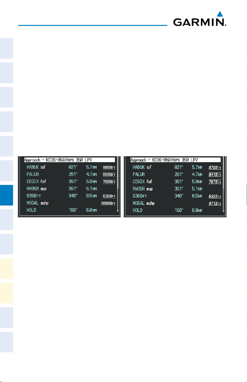
Procedures
ACTIVATE A MISSED APPROACH IN THE ACTIVE FLIGHT PLAN
Flight
Nav/Com/
InstrumentsEAS
XPDR/AudioAFCSGPS Nav
1)
Press the PROC Key.
2)
Turn the large FMS Knob to highlight ‘ACTIVATE MISSED APPROACH’.
3)
Press the ENT Key. A confirmation window is displayed.
4)
With ‘ACTIVATE’ highlighted, press the ENT Key.
Or:
Press the go-around button.
TEMPERATURE COMPENSATED ALTITUDE
When temperature compensated altitude is enabled for the loaded approach, the
altitudes associated with the approach waypoints are displayed in slanted text.
Flight
PlanningProcedures
Hazard
Avoidance
Altitudes Displayed Without
Temperature Compensation
Altitudes Displayed With
Temperature Compensation
Features
Additional
Abnormal
Operation
AlertsAppendixIndex
Annun/
Enabling temperature compensated altitude:
1)
From the Active Flight Plan Page, press the MENU Key. The Page Menu is
displayed.
2)
Turn the FMS Knob to highlight ‘Temperature Compensation’.
3)
Press the ENT Key. The TEMPERATURE COMPENSATION Window is
displayed.
4)
Use the small FMS Knob to select the temperature at the <airport>. The
compensated altitude is computed as the temperature is selected.
5)
Press the ENT Key. ‘ACTIVATE COMPENSATION?’ is highlighted.
6)
Press the ENT Key. The compensated altitudes for the approach are
shown in the flight plan.
48
Garmin G1000 Cockpit Reference Guide for the Socata TBM 850/900
190-00708-05 Rev. C
Page 67

Procedures
Disabling temperature compensated altitude:
1)
From the Active Flight Plan Page, press the MENU Key. The Page Menu is
displayed.
2)
Turn the FMS Knob to highlight ‘Temperature Compensation’.
3)
Press the ENT Key. The TEMPERATURE COMPENSATION Window is
displayed.
4)
Press the ENT Key. ‘CANCEL COMPENSATION?’ is highlighted.
5)
Press the ENT Key. The temperature compensated altitude at the FAF
is cancelled.
Instruments EAS
Flight
XPDR/Audio AFCS GPS Nav
Nav/Com/
Planning Procedures
Flight
Avoidance
Hazard
190-00708-05 Rev. C 49
Garmin G1000 Cockpit Reference Guide for the Socata TBM 850/900
Additional
Features
Operation
Abnormal
Annun/
Alerts Appendix Index
Page 68

Procedures
Flight
InstrumentsEAS
Nav/Com/
XPDR/AudioAFCSGPS Nav
Flight
PlanningProcedures
Blank Page
Hazard
Avoidance
Features
Additional
Abnormal
Operation
AlertsAppendixIndex
Annun/
50
Garmin G1000 Cockpit Reference Guide for the Socata TBM 850/900
190-00708-05 Rev. C
Page 69

Hazard Avoidance
HAZARD AVOIDANCE
CUSTOMIZING THE HAZARD DISPLAYS ON THE NAVIGATION MAP
1)
With the Navigation Map Page displayed, press the MENU Key to display
the Navigation Map Page Menu. The cursor flashes on the ‘Map Setup’
option.
2)
Press the ENT Key. The Map Setup Menu is displayed. Turn the small FMS
Knob to select ‘Weather’ to customize the display of weather features.
Select ‘Traffic’ to customize the display of traffic.
3)
Press the small FMS Knob to return to the Navigation Map Page.
STORMSCOPE® (OPTIONAL)
WARNING: The Stormscope system is not intended to be used for hazardous
thunderstorm penetration. Weather information on the G1000 MFD is
approved for weather avoidance only. Refer to the WX-500 Pilot’s Guide for
detailed operation.
Displaying Stormscope Lightning Data on the Navigation Map Page
Instruments EAS
Flight
XPDR/Audio AFCS GPS Nav
Nav/Com/
Planning Procedures
Flight
1)
Select the MAP Softkey.
2)
Select the STRMSCP Softkey. Select the STRMSCP Softkey again to
remove Stormscope Lightning Data from the Navigation Map Page.
Lightning Age Symbol
Strike is less than 6 seconds old
Strike is between 6 and 60 seconds old
Strike is between 1 and 2 minutes old
Strike is between 2 and 3 minutes old
Select ‘Cell’ or ‘Strike’ as the Stormscope Lightning Mode
1)
Press the MENU Key (with the Navigation Map Page displayed).
2)
Turn either FMS Knob to highlight ‘Map Setup’.
3)
Press the ENT Key.
4)
Turn the small FMS Knob to highlight ‘Weather’.
190-00708-05 Rev. C 51
Garmin G1000 Cockpit Reference Guide for the Socata TBM 850/900
Avoidance
Hazard
Additional
Features
Operation
Abnormal
Annun/
Alerts Appendix Index
Page 70

Hazard Avoidance
5)
Press the ENT Key.
6)
Flight
InstrumentsEAS
Turn the large FMS Knob to place the cursor in the ‘STRMSCP MODE’ field.
7)
Turn the small FMS Knob to display the ‘Cell/Strike’ window.
8)
Turn either FMS Knob to select ‘Cell’ or ‘Strike’. Press the ENT Key.
9)
Push the FMS Knob to return to the Navigation Map Page.
Clear Stormscope Lightning Data from the Navigation Map Page
Nav/Com/
XPDR/AudioAFCSGPS Nav
1)
Press the MENU Key (with the Navigation Map Page displayed).
2)
Turn either FMS Knob to highlight the ‘Clear Stormscope® Lightning’ field
and press the ENT Key.
Flight
Stormscope Page
PlanningProcedures
1)
2)
Change the Stormscope Lightning Mode Between ‘Cell’ and ‘Strike’
Hazard
Additional
Abnormal
Annun/
1)
Avoidance
2)
Features
Operation
AlertsAppendixIndex
Change the Viewing Mode Between 360˚ and 120˚
1)
2)
NOTE:
If heading input is lost, strikes and/or cells must be cleared manually
after the execution of each turn. This is to ensure that the strike and/or cell
positions are depicted accurately in relation to the nose of the aircraft.
Turn the large FMS Knob until the Map Page group is selected.
Turn the small FMS Knob until the Stormscope Page is selected.
Select the Stormscope Page.
Select the MODE Softkey. The CELL and STRIKE Softkeys are displayed.
Select the CELL Softkey to display ‘CELL’ data or select the STRIKE Softkey
to display ‘STRIKE’ data. ‘CELL’ or ‘STRIKE’ is displayed in the mode box
located in the upper left corner of the Stormscope Page.
NOTE: “Cell mode” uses a clustering program to identify clusters of electrical
activity that indicate cells.
Select the Stormscope Page.
Select the VIEW Softkey. The 360 and ARC Softkeys are displayed. Select
the 360 Softkey to display a 360˚ viewing area or select the ARC Softkey to
display a 120˚ viewing area.
Select the CLEAR Softkey to remove all Stormscope lightning data from the
display.
52
Garmin G1000 Cockpit Reference Guide for the Socata TBM 850/900
190-00708-05 Rev. C
Page 71

Hazard Avoidance
SIRIUSXM WEATHER (OPTIONAL)
WARNING: Use of SiriusXM Weather for hazardous weather penetration is
not recommended. Weather information provided by SiriusXM is approved
only for weather avoidance, not penetration.
Displaying SiriusXM Weather on the Navigation Map Page
1)
Select the MAP Softkey.
2)
Select the NEXRAD or XM LTNG Softkey to display the desired weather.
Select the applicable softkey again to remove weather data from the
Navigation Map Page.
Display METAR and TAF information on the Airport Information Page
1)
Turn the large FMS Knob to select the WPT Page Group.
2)
Turn the small FMS Knob to select the Airport Information Page.
3)
Select the WX Softkey to display METAR and TAF text (METAR and TAF
information is updated every 12 minutes).
Displaying Weather on the Weather Data Link Page
1)
Turn the large FMS Knob to select the Map Page Group.
2)
Turn the small FMS Knob to select the Weather Data Link Page.
3)
Select the available softkeys to select the desired SiriusXM Weather product.
4)
Select the LEGEND Softkey to view the legends for the selected products.
If necessary, turn either FMS Knob to scroll through the list. Press the small
FMS Knob or the ENT Key to return to the map.
Instruments EAS
Flight
XPDR/Audio AFCS GPS Nav
Nav/Com/
Planning Procedures
Flight
Avoidance
Hazard
Additional
Features
Operation
Abnormal
Map Panning Information – Weather Data Link Page
1)
Push in the Joystick to display the panning arrow.
2)
Move the Joystick to place the panning arrow on AIRMETs, TFRs, METARs,
SIGMETs, PIREPs or AIREPs.
3)
Press the ENT Key to display pertinent information for the selected product.
Note that pressing the ENT Key when panning over an AIRMET or a
SIGMET displays an information box that shows the text of the report.
Panning over an airport with METAR information does not display more
190-00708-05 Rev. C 53
Garmin G1000 Cockpit Reference Guide for the Socata TBM 850/900
Alerts Appendix Index
Annun/
Page 72

Hazard Avoidance
information but allows the user to press the ENT Key and select that
Flight
InstrumentsEAS
Airport’s Information Page to display the text of the report. Pressing the
ENT Key when panning over a TFR displays TFR specific information.
Weather Products and Symbols
Nav/Com/
XPDR/AudioAFCSGPS Nav
Flight
PlanningProcedures
Hazard
Avoidance
Features
Additional
Abnormal
Operation
Wx Product
Status Icons
Description
NEXRAD - Available for the US and Canada. The age of the displayed data
for each is shown at the right.
ECHO TOP - The age of the displayed data is shown at the right. Not
displayed when CLOUD TOP is displayed.
CLOUD TOP - The age of the displayed data is shown at the right. Not
displayed when ECHO TOP is displayed.
XM LIGHTNING - The age of the displayed data is shown at the right.
CELL MOVEMENT - The age of the displayed data is shown at the right.
SIGMET & AIRMET - The age of the displayed data for each is shown at the
right.
METAR - Available for the US and Canada. The age of the displayed data for
each is shown at the right.
SURFACE ANALYSIS with CITY FORECAST - The upper symbol depicts
Surface Analysis. The lower symbol depicts City Forecast. The age of the
displayed data for each is shown at the right. The selected forecast period is
shown at the bottom.
AlertsAppendixIndex
Annun/
54
FREEZING LEVEL - The age of the displayed data is shown at the right.
WINDS ALOFT - Available for the US and Canada. The age of the displayed
data for each is shown at the right. The altitude selection is shown at the
bottom.
COUNTY WARNING - The age of the displayed data is shown at the right.
Garmin G1000 Cockpit Reference Guide for the Socata TBM 850/900
190-00708-05 Rev. C
Page 73

Hazard Avoidance
Wx Product
Status Icons
Description
CYCLONE WARNING - The age of the displayed data is shown at the right.
AIREP - The age of the displayed data is shown at the right.
PIREP - The age of the displayed data is shown at the right. Urgent Pireps
are displayed in yellow.
TURBULENCE - The age of the displayed data is shown at the right. The
altitude selection is shown at the bottom.
ICING POTENTIAL - The age of the displayed data is shown at the right.
The altitude selection is shown at the bottom.
GARMIN CONNEXT™ WEATHER
NOTE: Garmin Connext Weather provides information for avoiding hazardous
weather. Do not utilize Connext Weather information to penetrate hazardous
weather.
Registering the System to Receive Connext™ Weather
Instruments EAS
Flight
XPDR/Audio AFCS GPS Nav
Nav/Com/
Planning Procedures
Flight
Avoidance
Hazard
When an account is established, Garmin Connext provides an Access Code which
must be entered on the G1000 in order to complete the registration process.
1)
With the aircraft outside and having a clear view of the sky, turn the large
FMS Knob on the MFD to select the MAP page group.
2)
Turn the small FMS Knob to select the MAP-WEATHER DATA LINK (Connext
or XM) Page. If ‘XM’ is displayed in the page title, it will be necessary
to change the datalink source to Connext before continuing. Refer to
‘Viewing the Weather Data Link Page’ procedure to change the datalink
source to Connext prior to registration.
3)
If the system displays the ‘Garmin Flight Data Service Registration’ window,
proceed to step 7. Otherwise, press the MENU Key. The Page Menu
window is now displayed.
4)
Turn the large FMS Knob to select ‘Register With Connext’ in the menu list.
190-00708-05 Rev. C 55
Garmin G1000 Cockpit Reference Guide for the Socata TBM 850/900
Additional
Features
Operation
Abnormal
Annun/
Alerts Appendix Index
Page 74

Hazard Avoidance
5)
Press the ENT Key. The Garmin Flight Data Service Registration window is
Flight
InstrumentsEAS
now displayed.
6)
Enter the access code provided by Garmin Connext in the ACCESS CODE
field.
7)
Press the ENT Key. ‘REGISTER’ will now be highlighted.
8)
Press the ENT Key. The system will contact Garmin Connext. System
registration is complete when ‘REGISTERED’ is displayed in the STATUS
Nav/Com/
XPDR/AudioAFCSGPS Nav
field.
Accessing Connext Weather Products
Weather data is provided when the pilot initiates either a manual or automatic
Connext data request on the Connext Weather Data Link Page on the MFD. No
weather data is displayed until the first Connext Weather Data Request is made.
1)
Flight
Turn the large
2)
PlanningProcedures
Turn the small
FMS
Knob to select the Map Page Group.
FMS
Knob to select the Connext Weather Data Link Page.
When a weather product is selected for display on the Connext Weather Data Link
Page, a box containing a symbol for the product and its age (in minutes) are shown
in the upper right. If weather data has not been requested, ‘N/A’ is shown next to the
product symbol instead of age. The age of the weather product is based on the time
difference between when the data was assembled on the ground and the current GPS
Hazard
Avoidance
time. Weather products are updated continuously or refreshed at specific intervals
(defined in the Refresh Rate column in the following table).
If for any reason, a weather product is not refreshed within the defined Expiration
Features
Additional
Time intervals, the data is considered expired and is removed from the display. The
age of the expired product is replaced by dashes. If more than half of the expiration
time has elapsed, the color of the product age readout changes to yellow.
Abnormal
Operation
The refresh rate represents the interval at which the Connext servers make available
the most current known weather data. It does not necessarily represent the rate at
AlertsAppendixIndex
Annun/
which new content is received from weather sources.
56
Garmin G1000 Cockpit Reference Guide for the Socata TBM 850/900
190-00708-05 Rev. C
Page 75

Hazard Avoidance
Instruments EAS
Flight
XPDR/Audio AFCS GPS Nav
Nav/Com/
Planning Procedures
Flight
Avoidance
Hazard
Additional
Features
Weather Product Symbol
Radar Precipitation
(PRECIP)
Infrared Satellite
(IR SAT)
Datalink Lightning
(DL LTNG)
SIGMETs/AIRMETs
(SIG/AIR)
Meteorological Aerodrome Report
(METARs)
Winds Aloft
(WIND)
Pilot Weather Report
(PIREPs)
Temporary Flight Restrictions
(TFRs)
Terminal Aerodrome Reports
(TAFs)
Expiration
Time
(Minutes)
30
60 30
30 Continuous
60 Continuous
90 Continuous
60 Continuous
90 Continuous
no product image 60 Continuous
no product image 60 Continuous
Refresh Rate
(Minutes)
U.S./Canada: 3*
Europe: 15
* The composite precipitation image is updated every 3 minutes, but individual radar sites
may take between 3 and 10 minutes to provide new data.
Setting Up and Customizing the Connext Weather Data Link Page
1)
Select the Connext Weather Data Link Page.
2)
Press the
3)
With ‘Weather Setup’ highlighted, press the
4)
Turn the small
and press the
5)
Turn the large
selections.
6)
Turn the small
OFF, range settings, etc.).
190-00708-05 Rev. C 57
MENU
Key.
ENT
Key.
FMS
Knob to select ‘Product Group 1’ or ‘Product Group 2’,
ENT
Key.
FMS
Knob or press the
FMS
Knob to scroll through options for each product (ON/
Garmin G1000 Cockpit Reference Guide for the Socata TBM 850/900
ENT
Key to scroll through product
Operation
Abnormal
Annun/
Alerts Appendix Index
Page 76

Hazard Avoidance
7)
Flight
InstrumentsEAS
Press the
8)
Press the FMS Knob or CLR Key to return to the Connext Weather Data
Link Page with the changed settings.
ENT
Key to select an option.
Restoring Default Connext Weather Data Link Page Settings
1)
Select the Connext Weather Data Link Page.
2)
Press the MENU Key.
Nav/Com/
XPDR/AudioAFCSGPS Nav
3)
With ‘Weather Setup’ highlighted, press the
4)
Press the
5)
Highlight the desired default(s) to restore (all or for selection) and press
MENU
Key.
ENT
Key.
ENT Key.
Switching Between Connext and SiriusXM Weather Sources
1)
Turn the large FMS Knob on the MFD to select the MAP page group.
2)
Flight
PlanningProcedures
Turn the small FMS Knob to select the desired Weather Data Link Page.
3)
Press the MENU Key.
4)
Turn the large FMS Knob to select ‘Display Connext Weather’ or ‘Display
XM’ Weather’ (choice dependent on current weather source) and press the
ENT Key.
Viewing Legends for Displayed Connext Weather Products
Hazard
Avoidance
1)
Select the Connext Weather Data Link Page.
2)
Features
Additional
Abnormal
Operation
AlertsAppendixIndex
Annun/
Select the LEGEND Softkey to display the legends for the displayed
weather products.
Or
:
a)
Press the MENU Key.
b)
Select ‘Weather Legend’ and press the ENT Key.
3)
Turn the FMS Knob to scroll through the legends if more are available than
fit in the window.
4)
To remove the Legend Window, select the LEGEND Softkey, the ENT or the
CLR Key, or press the FMS Knob.
58
Garmin G1000 Cockpit Reference Guide for the Socata TBM 850/900
190-00708-05 Rev. C
Page 77

Hazard Avoidance
Setting Up and Customizing Weather Data for the Navigation Map
Instruments EAS
Flight
Page
1)
Select the Navigation Map Page.
2)
Press the MENU Key.
3)
With ‘Map Setup’ highlighted, press the
4)
Turn the small FMS Knob to select the ‘Weather’ Group and press the ENT
ENT
Key.
XPDR/Audio AFCS GPS Nav
Nav/Com/
Key.
5)
Turn the large
FMS
Knob or press the
ENT
Key to scroll through product
selections.
6)
Turn the small
FMS
Knob to scroll through options for each product (ON/
OFF, range settings).
7)
Press the
8)
Press the FMS Knob or CLR Key to return to the Navigation Map Page with
the changed settings.
ENT
Key to select an option.
Planning Procedures
Flight
Connext Weather Data Requests
The Connext Data Request window provides the flight crew with the options to
define the requested weather coverage area(s), choose automatic weather update
intervals (if desired), and the ability to send or cancel weather data requests. The
Avoidance
Hazard
window also displays the status of the Connext data request process.
Requesting Connext Weather Data Manually
1)
Select the Connext Weather Data Link Page.
2)
Press the MENU Key.
3)
With ‘Connext Weather Request’ highlighted, press the
4)
Turn the large FMS Knob to highlight the desired coverage option(s)
and press the
ENT
Key to check or uncheck one of more of the following
coverage selections:
• PRESENT POSITION – Requests data based on current location.
• DESTINATION – Requests data based on active flight plan destination (if the flight
plan contains no destination, dashes ‘------” are displayed.)
• FPL – Requests data based on active flight plan. Turn the small FMS Knob to select
the desired flight plan look-ahead distance option (or choose ‘REMAINING FPL’ to
request the remainder of the flight plan).
• WAYPOINT – Requests data based on any valid waypoint.
190-00708-05 Rev. C 59
Garmin G1000 Cockpit Reference Guide for the Socata TBM 850/900
ENT
Key.
Additional
Features
Operation
Abnormal
Annun/
Alerts Appendix Index
Page 78

Hazard Avoidance
5)
Turn the large FMS Knob highlight to the ‘DIAMETER / RTE WIDTH’
Flight
InstrumentsEAS
distance field and turn the small FMS Knob to select the desired diameter
and route width of the request, then press the
6)
Turn the large FMS Knob until the ‘SEND REQ’ button is highlighted. Press
the
ENT
return to the Connext Data Link Page without requesting data.
ENT
Key.
Key to initiate the request immediately or press the FMS Knob to
Nav/Com/
XPDR/AudioAFCSGPS Nav
Connext...”. Once a connection is established, the Request Status Box displays “Receiving
Wx Data... Time Remaining:” with an estimated data transfer time (either minutes or
seconds). If desired, the Connext Data Request window may be closed while the data
request is processing by pressing the FMS Knob; the data request will continue to process
in the background. Connext Data Requests typically take between 1 to 4 minutes to
complete depending on the size of the selected weather coverage area and Iridium signal
strength.
The system retrieves all available Worldwide Weather products within the selected
During a Connext Data Request, the Request Status box initially displays “Contacting
Flight
coverage area during an initial Connext Data Request, regardless of which products (if
PlanningProcedures
any) are currently enabled for display. On subsequent requests, previously retrieved
textual data (such as METARs and TAFS) is retained if it has not expired, while new
textual weather data matching the current coverage area and all graphical weather data is
downloaded during every data request.
If the system cannot complete a Connext weather data request, one or more mes-
Hazard
Avoidance
sages will appear in the request status window as indicated in the following table.
Weather Request
Features
Additional
Abnormal
Status Message
Auto requests inhibited
Send manual request to
Operation
reset.
The system has disabled automatic weather data requests due to
excessive errors. Automatic weather data requests have stopped. Send
a manual weather data request to resume automatic updates.
Description
Auto update retry: ##
AlertsAppendixIndex
Annun/
Seconds
The system will attempt another automatic weather data request after
an error occurred during the previous request. Timer counts down until
the next automatic request occurs.
Connext Comm Error [2] A communications error has occurred with the GDL59 or GIA. The
G1000 should be serviced.
Connext Comm Error [4] This occurs if multiple automatic weather data requests have recently
failed, or the GDL 59 or a GIA is off-line.
60
Garmin G1000 Cockpit Reference Guide for the Socata TBM 850/900
190-00708-05 Rev. C
Page 79

Hazard Avoidance
Weather Request
Description
Status Message
Connext Comm Error [5] This can occur if the GDL 59 is off-line or not configured, or the Iridium
or Connext networks are not accessible. Check Iridium signal strength.
If this error persists, the G1000 should be serviced.
Connext Comm Error [6] A communications error has occurred. It this error persists, the G1000
should be serviced.
Connext Comm Error [7] A weather data transfer has timed out. Check Iridium signal strength
and re-send the data request.
Connext Comm Error [8] A server error has occurred or invalid data received.
Connext Login Invalid There is a problem with the Connext registration. Contact Garmin at
1-866-739-5687 in the United States or 913-397-8200, ext. 1135 for
assistance.
Connext Server
Temporarily Inop
Connext Server Inop The Connext weather data server will be out of service for at least 30
Invalid Coverage Area The weather data request coverage area does not contain at least one
NO Connext Subscription The system is not be currently subscribed to Connext, or the access code
Reduce Request Area The Connext weather data request area exceeds size limits. Reduce
Request Cancelled The user has cancelled a Connext weather data request.
Requested area too
large. Reduce coverage
area.
The Connext weather data server is temporarily out of service, but is
expected to return to service in less than 30 minutes.
minutes.
of the following: a waypoint, a flight plan, or a flight plan destination.
Verify at least one of the coverage options is enabled (checked) and
contains required criteria, then re-send the data request.
is incorrect. Verify the access code. Contact Garmin at 1-866-739-5687
in the United States or 913-397-8200, ext. 1135 for assistance.
weather coverage area and re-send data request.
The size of the Connext weather data request has exceeded limits.
Reduce the size of the coverage area and try the weather data request
again.
Instruments EAS
Flight
XPDR/Audio AFCS GPS Nav
Nav/Com/
Planning Procedures
Flight
Avoidance
Hazard
Additional
Features
Operation
Abnormal
Annun/
Alerts Appendix Index
Request Failed - Try
The weather data request timed-out. Re-send data request.
Again
Transfer Preempted
190-00708-05 Rev. C 61
The GDL 59 is busy. Retry request later.
Garmin G1000 Cockpit Reference Guide for the Socata TBM 850/900
Page 80

Hazard Avoidance
Cancelling a Connext Weather Data Request in Progress
Flight
InstrumentsEAS
Nav/Com/
XPDR/AudioAFCSGPS Nav
Flight
PlanningProcedures
Hazard
Avoidance
Features
Additional
1)
Select the Connext Weather Data Link Page.
2)
Press the
3)
With ‘Connext Data Request’ highlighted, press the
4)
Turn the large
MENU
FMS
Key.
ENT
Knob to select ‘CANCEL REQ’ and press the
Key.
The request status box indicates ‘Request Cancelled’.
5)
Press the FMS Knob to return to the Connext Weather Datalink Page.
Enabling Automatic Connext Data Requests
1)
Select the Connext Weather Data Link Page.
2)
Press the MENU Key.
3)
With ‘Connext Weather Request’ highlighted, press the
4)
Choose the desired weather coverage options.
5)
Turn the large FMS Knob to select the ‘UPDATE RATE’ setting. Then turn
the small FMS Knob to highlight the desired automatic update frequency
(OFF, 5 Min, 10 Min, 15 Min, 20 Min, 25 Min, 30 Min, 45 Min, or 60 Min),
then press the ENT Key.
6)
The ‘SEND REQ” button is highlighted and a countdown timer is displayed
in the ‘REQUEST STATUS’ based on the currently selected update rate.
Press the ENT Key to immediately send an immediate Connext Data
Request.
Or
:
Press the FMS Knob to return to the Connext Weather Data Link Page.
ENT
Key.
ENT
Key.
Abnormal
Operation
AlertsAppendixIndex
Annun/
62
Garmin G1000 Cockpit Reference Guide for the Socata TBM 850/900
190-00708-05 Rev. C
Page 81

Hazard Avoidance
TRAFFIC SYSTEMS
• If Traffic information Service (TIS) is configured, STANDBY, OPERATE, and
TNA MUTE softkeys are displayed.
• If a Traffic Advisory System (TAS) is configured, STANDBY, NORMAL, TEST,
and ALT MODE softkeys are displayed.
Traffic Symbol Description
Non-Threat Traffic
(intruder is beyond 5 nm and greater than 1200’ vertical separation)
Proximity Advisory (PA) (Not available with TIS system)
(intruder is within 5 nm and less than 1200’ vertical separation)
Traffic Advisory (TA)
(closing rate, distance, and vertical separation meet TA criteria)
Traffic Advisory Off Scale
Traffic Symbol Description
Traffic Information Service (TIS)
NOTE: If the G1000 is configured to use an optional Traffic Advisory System
(TAS), TIS is not available for use.
Instruments EAS
Flight
XPDR/Audio AFCS GPS Nav
Nav/Com/
Planning Procedures
Flight
Avoidance
Hazard
NOTE: Traffic Information Service (TIS) is only available when the aircraft is
within the service volume of a TIS capable terminal radar site.
Displaying Traffic on the Traffic Map Page
1)
Turn the large FMS Knob to select the Map Page Group.
2)
Turn the small FMS Knob to select the Traffic Map Page.
3)
Select the OPERATE Softkey to begin displaying traffic. ‘OPERATING’ is
displayed in the Traffic Mode field.
4)
Select the STANDBY Softkey to place the system in the Standby Mode.
‘STANDBY’ is displayed in the Traffic Mode field.
5)
Rotate the Joystick clockwise to display a larger area or rotate counterclockwise to display a smaller area.
6)
Select the TNA MUTE Softkey to mute the “Traffic Not Available” aural alert.
190-00708-05 Rev. C 63
Garmin G1000 Cockpit Reference Guide for the Socata TBM 850/900
Additional
Features
Operation
Abnormal
Annun/
Alerts Appendix Index
Page 82

Hazard Avoidance
Displaying Traffic on the Navigation Map
Flight
InstrumentsEAS
1)
Ensure TIS is operating. With the Navigation Map displayed, select the
MAP Softkey.
2)
Select the TRAFFIC Softkey. Traffic is now displayed on the map.
Traffic Advisory System (TAS) (Optional)
Nav/Com/
Flight
Hazard
Additional
Abnormal
Annun/
System Self Test
XPDR/AudioAFCSGPS Nav
1)
Set the range to 2/6 nm.
2)
Select the STANDBY Softkey.
3)
Select the TEST Softkey.
4)
Self test takes approximately eight seconds to complete. When completed
successfully, traffic symbols are displayed and a voice alert “TAS System Test
OK” is heard. If the self test fails, the system reverts to Standby Mode and
PlanningProcedures
a voice alert “TAS System Test Fail” is heard.
Displaying Traffic on the Traffic Map Page
1)
Turn the large FMS Knob to select the Map Page Group.
2)
Turn the small FMS Knob to select the second rectangular page icon.
3)
Select the NORMAL Softkey to begin displaying traffic. ‘OPERATING’ is
displayed in the Traffic Mode field.
Avoidance
4)
Select the ALT MODE Softkey to change the altitude volume. Select the
desired altitude volume by selecting the BELOW, NORMAL, ABOVE, or
Features
UNREST (unrestricted) Softkey. The selection is displayed in the Altitude
Mode field.
5)
Select the STANDBY Softkey to place the system in the Standby Mode.
Operation
AlertsAppendixIndex
‘STANDBY’ is displayed in the Traffic Mode field.
6)
Rotate the Joystick clockwise to display a larger area or rotate counterclockwise to display a smaller area.
7)
Select the FLT ID Softkey (GTS 820 only) to enable or disable Flight ID
displayed with the intruder information.
Displaying Traffic on the Navigation Map
1)
Ensure TAS is operating.
2)
With the Navigation Map displayed, select the MAP Softkey.
3)
Select the TRAFFIC Softkey. Traffic is now displayed on the map.
64
Garmin G1000 Cockpit Reference Guide for the Socata TBM 850/900
190-00708-05 Rev. C
Page 83

Hazard Avoidance
TERRAIN AND OBSTACLE PROXIMITY
NOTE: Terrain data is not displayed when the aircraft latitude is greater than
75 degrees north or 60 degrees south.
Displaying Terrain and Obstacles on the Terrain Proximity Page
1)
Turn the large
2)
Turn the small
3)
If desired, select the
When the
Select the
4)
Rotate the
clockwise to display a smaller area.
FMS
Knob to select the Map Page Group.
FMS
Knob to select the last rectangular page icon.
VIEW
Softkey to access the
ARC
Softkey is selected, a radar-like 120° view is displayed.
360
Softkey to return to the 360° default display.
Joystick
clockwise to display a larger area or rotate counter-
ARC
and
360
Color Terrain/Obstacle Location
Red
Yellow
Black
Terrain/Obstacle above or within 100’
below current aircraft altitude.
Terrain/Obstacle between 100’ and
1000’ below current aircraft altitude.
Terrain/Obstacle is more than 1000’
below aircraft altitude.
Softkeys.
Instruments EAS
Flight
XPDR/Audio AFCS GPS Nav
Nav/Com/
Planning Procedures
Flight
Avoidance
Hazard
Displaying Terrain and Obstacles on the Navigation Map
1)
With the Navigation Map displayed, select the
2)
Select the
TERRAIN
Softkey. Terrain and obstacle proximity will now be
MAP
Softkey.
displayed on the map.
TERRAIN-SVT
NOTE: Terrain-SVT is only available when the Synthetic Vision Technology
(SVT) option is installed and the TAWS option has not been installed.
NOTE: Terrain data is not displayed when the aircraft latitude is greater than
75 degrees north or 60 degrees south.
190-00708-05 Rev. C 65
Garmin G1000 Cockpit Reference Guide for the Socata TBM 850/900
Additional
Features
Operation
Abnormal
Annun/
Alerts Appendix Index
Page 84

Hazard Avoidance
Display Terrain on the TERRAIN-SVT Page
Flight
InstrumentsEAS
1)
Turn the large FMS Knob to select the Map Page Group.
2)
Turn the small FMS Knob to select the Terrain-SVT Page.
3)
If desired, select the VIEW Softkey to access the ARC and 360 softkeys.
When the ARC Softkey is selected, a radar-like 120° view is displayed.
Select the 360 Softkey to return to the 360° default display.
4)
Nav/Com/
XPDR/AudioAFCSGPS Nav
Rotate the Joystick clockwise to display a larger area or rotate counterclockwise to display a smaller area.
Flight
PlanningProcedures
Enable/Disable Aviation Data
1)
While the Terrain-SVT Page is displayed, press the MENU Key.
2)
Hazard
Avoidance
Turn the small FMS Knob to select “Show (or Hide) Aviation Data”.
3)
Press the ENT Key.
Color Terrain/Obstacle Location
Red
Yellow
Black
Terrain/Obstacle above or within 100’
below current aircraft altitude.
Terrain/Obstacle between 100’ and
1000’ below current aircraft altitude.
Terrain/Obstacle is more than 1000’
below aircraft altitude.
Features
Terrain-SVT Inhibit
Additional
Inhibit Terrain
Abnormal
Operation
While the Terrain-SVT Page is displayed, select the INHIBIT Softkey.
Or
1)
AlertsAppendixIndex
Annun/
Press the MENU Key.
2)
Turn the small FMS Knob to select ‘Inhibit Terrain’.
3)
Press the ENT Key.
Enable Terrain
While the Terrain-SVT Page is displayed, select the INHIBIT Softkey.
Or
66
:
:
Garmin G1000 Cockpit Reference Guide for the Socata TBM 850/900
190-00708-05 Rev. C
Page 85

Hazard Avoidance
1)
While the Terrain-SVT Page is displayed, press the MENU Key.
2)
Turn the small FMS Knob to select ‘Enable Terrain’.
3)
Press the ENT Key.
NOTE: If Terrain-SVT alerts are inhibited when the Final Approach Fix is the
active waypoint in a GPS SBAS approach, a LOW ALT annunciation may appear
on the PFD next to the altimeter if the current aircraft altitude is at least 164
feet below the prescribed altitude at the Final Approach Fix.
TERRAIN AWARENESS & WARNING SYSTEM (TAWS-B) DISPLAY
WARNING: The TAWS-B display shows supplemental information only. It
should not be used for navigation.
NOTE: Terrain data is not displayed when the aircraft latitude is greater than
75 degrees north or 60 degrees south.
NOTE: TAWS operation is only available when the G1000 is configured for a
TAWS-B installation.
Manual System Test
Instruments EAS
Flight
XPDR/Audio AFCS GPS Nav
Nav/Com/
Planning Procedures
Flight
Avoidance
Hazard
1)
While the TAWS-B Page is displayed, press the MENU Key.
2)
Turn the small FMS Knob to select ‘Test TAWS’.
3)
Press the ENT Key. During the test ‘TAWS TEST’ is displayed in the center
of the TAWS-B Page.
When all is in working order, “TAWS System Test, OK” is heard.
Display Terrain on the TAWS-B Page
1)
Turn the large FMS Knob to select the Map Page Group.
2)
Turn the small FMS Knob to select the TAWS-B Page.
3)
If desired, select the VIEW Softkey to access the ARC and 360 softkeys.
When the ARC Softkey is selected, a radar-like 120° view is displayed.
Select the 360 Softkey to return to the 360° default display.
190-00708-05 Rev. C 67
Garmin G1000 Cockpit Reference Guide for the Socata TBM 850/900
Additional
Features
Operation
Abnormal
Annun/
Alerts Appendix Index
Page 86

Hazard Avoidance
4)
Rotate the Joystick clockwise to display a larger area or rotate counter-
Flight
InstrumentsEAS
Nav/Com/
XPDR/AudioAFCSGPS Nav
clockwise to display a smaller area.
Enable/Disable Aviation Data
1)
While the TAWS-B Page is displayed, press the MENU Key.
2)
Turn the small FMS Knob to select “Show (or Hide) Aviation Data”.
3)
Press the ENT Key.
Flight
PlanningProcedures
TAWS Inhibit
NOTE: If TAWS alerts are inhibited when the Final Approach Fix is the active
waypoint in a GPS SBAS approach, a LOW ALT annunciation may appear on
the PFD next to the altimeter if the current aircraft altitude is at least 164
Hazard
Avoidance
feet below the prescribed altitude at the Final Approach Fix.
Color Terrain/Obstacle Location
Red
Yellow
Black
Terrain/Obstacle above or within 100’
below current aircraft altitude.
Terrain/Obstacle between 100’ and
1000’ below current aircraft altitude.
Terrain/Obstacle is more than 1000’
below aircraft altitude.
Features
Additional
Abnormal
Operation
AlertsAppendixIndex
Annun/
Inhibit TAWS
While the TAWS-B Page is displayed, select the INHIBIT Softkey.
Or
:
1)
Press the MENU Key.
2)
Turn the small FMS Knob to select ‘Inhibit TAWS’.
3)
Press the ENT Key.
Enable TAWS
While the TAWS-B Page is displayed, select the INHIBIT Softkey.
Or
:
1)
While the TAWS-B Page is displayed, press the MENU Key.
2)
Turn the small FMS Knob to select ‘Enable TAWS’.
3)
Press the ENT Key.
68
Garmin G1000 Cockpit Reference Guide for the Socata TBM 850/900
190-00708-05 Rev. C
Page 87

Hazard Avoidance
AIRBORNE COLOR WEATHER RADAR
WARNING: Begin transmitting only when it is safe to do so. If it is desired to
transmit while the aircraft is on the ground, no personnel or objects should
be within 11 feet of the antenna.
CAUTION: In Standby Mode, the antenna is parked at the center line. It
is always a good idea to put the radar in Standby Mode before taxiing the
aircraft to prevent the antenna from bouncing on the bottom stop and possibly
causing damage to the radar assembly.
Displaying Weather on the Navigation Map Page
1)
Turn the large FMS Knob to select the Map Page Group.
2)
Turn the small FMS Knob to select the Navigation Map Page.
3)
Select the MAP Softkey.
4)
Select the WX RADAR Softkey.
Displaying Weather on the Weather Radar Page
1)
Turn the large FMS Knob to select the Map Page Group.
2)
Turn the small FMS Knob to select the Weather Radar Page.
3)
Select the MODE Softkey.
4)
If the aircraft is on the ground, select the STANDBY Softkey to initiate the
one minute warm-up period. After the warm-up is complete, the radar will
enter the Standby Mode. After the aircraft is airborne, select the WEATHER
Softkey.
Or
:
If the aircraft is already airborne, select the WEATHER or GROUND
Softkey. The one-minute warm-up period will be initiated, after which the
radar will begin transmitting. The horizontal scan is initially displayed.
5)
Turn the Joystick to select the desired range.
6)
If desired, select the VERTICAL Softkey for vertical scanning.
Instruments EAS
Flight
XPDR/Audio AFCS GPS Nav
Nav/Com/
Planning Procedures
Flight
Avoidance
Hazard
Additional
Features
Operation
Abnormal
Annun/
Alerts Appendix Index
190-00708-05 Rev. C 69
Garmin G1000 Cockpit Reference Guide for the Socata TBM 850/900
Page 88

Hazard Avoidance
Adjusting Antenna Tilt
Flight
While viewing weather radar on the Weather Radar Page or the Navigation Map
InstrumentsEAS
Page, moving the
Joystick
up or down adjusts the tilt of the antenna up or down.
Monitor the displayed tilt value in the TILT field.
When scanning vertically on the Weather Radar Page, a Tilt Line may be displayed
to aid in positioning the tilt of the antenna. If the Tilt Line is not displayed, perform
the following steps:
Nav/Com/
XPDR/AudioAFCSGPS Nav
1)
Press the MENU Key
2)
Turn the large FMS Knob to select ‘Show Tilt Line’.
3)
Press the ENT Key.
Adjusting Antenna Bearing
While viewing weather radar on the Weather Radar Page or the Navigation Map
Page, moving the
right or left. Monitor the displayed bearing value in the BEARING field.
Flight
PlanningProcedures
When scanning horizontally, a Bearing Line may be displayed to aid in positioning
Joystick
right or left adjusts the azimuth position of the antenna
the antenna for the vertical scan. If the Bearing Line is not displayed, perform the
following steps:
1)
Press the MENU Key
2)
Turn the large FMS Knob to select ‘Show Bearing Line’.
Hazard
Avoidance
3)
Press the ENT Key.
Vertically Scan a Storm Cell
Features
Additional
1) While in the Horizontal Scan view, move the Joystick to place the Bearing
Line on the desired storm cell, or other area, to be vertically scanned.
2)
Abnormal
Operation
Select the VERTICAL Softkey. A vertical ‘slice’ of the selected area will now
be displayed.
3)
AlertsAppendixIndex
Annun/
Move the Joystick right or left to move the scanned “slice” a few degrees
right or left.
4)
Turn the Joystick to adjust the range.
5)
To select a new area to be vertically scanned, select the HORIZON Softkey
to return to the Horizontal Scan view and repeat the previous steps.
70
Garmin G1000 Cockpit Reference Guide for the Socata TBM 850/900
190-00708-05 Rev. C
Page 89

Hazard Avoidance
Adjusting Gain
WARNING: Changing the gain in Weather Mode will cause precipitation
intensity to be displayed as a color not representative of the true intensity.
Remember to return the gain setting to ‘Calibrated’ for viewing the actual
intensity of precipitation.
1)
Select the GAIN Softkey to activate the cursor in the ‘GAIN’ field.
2)
Turn the small FMS Knob to adjust the gain for the desirable level. The
gain setting is visible in the gain field as a movable horizontal bar in
a flashing box. The line pointer is a reference depicting the calibrated
position.
3)
Press the FMS Knob to remove the cursor.
4)
Select the GAIN Softkey again to recalibrate the gain. ‘CALIBRATED’ will be
displayed in the ‘GAIN’ field.
Ground Mapping
1)
Press the MODE Softkey.
2)
Press the GROUND Softkey to place the radar in Ground Map Mode.
3)
Press the BACK Softkey.
4)
Press the FMS Knob to activate the cursor.
5)
Turn the large FMS Knob to place the cursor in the ‘TILT’ field.
6)
Adjust the antenna tilt angle by turning the small FMS Knob to position the
ground returns as desired.
7)
Press the FMS Knob to remove the cursor.
Sector Scan
1)
While in the Horizontal Scan Mode, move the Joystick right or left to place
the Bearing Line in the desired position. The location of the Bearing Line
will become the center point of the Sector Scan.
2)
Press the FMS Knob to display the cursor.
3)
Turn the large FMS Knob to place the cursor in the SECTOR SCAN field.
4)
Turn the small FMS Knob to select FULL, 60˚, 40˚, or 20˚ scan.
5)
If desired, readjust the Bearing Line with the Joystick to change the center
of the Sector Scan.
6)
Press the FMS Knob to remove the cursor.
Instruments EAS
Flight
XPDR/Audio AFCS GPS Nav
Nav/Com/
Planning Procedures
Flight
Avoidance
Hazard
Additional
Features
Operation
Abnormal
Annun/
Alerts Appendix Index
190-00708-05 Rev. C 71
Garmin G1000 Cockpit Reference Guide for the Socata TBM 850/900
Page 90

Hazard Avoidance
Antenna Stabilization
1)
Flight
InstrumentsEAS
To activate or deactivate the antenna stabilization, select the MODE
Softkey.
2)
Select the STAB ON Softkey to activate antenna stabilization or select
the STAB OFF Softkey to deactivate. The current stabilization condition is
shown in the upper right of the weather radar display.
Weather Attenuated Color Highlight (WATCH®)
Nav/Com/
XPDR/AudioAFCSGPS Nav
To activate or deactivate the WATCH® feature, select the WATCH Softkey. This
feature is only available in the Horizontal Scan Mode.
Weather Alert
To activate or deactivate Weather Alert, select the WX ALRT Softkey. Activating
and deactivating will also enable or inhibit the alert on the PFD.
Automatic Standby
Flight
PlanningProcedures
When the weather radar system is in the Weather or Ground Map Mode, upon
landing the system will automatically switch to Standby Mode.
Hazard
Avoidance
Features
Additional
Abnormal
Operation
AlertsAppendixIndex
Annun/
72
Garmin G1000 Cockpit Reference Guide for the Socata TBM 850/900
190-00708-05 Rev. C
Page 91

Additional Features
ADDITIONAL FEATURES
SYNTHETIC VISION
WARNING: Use appropriate primary systems for navigation, and for terrain,
obstacle, and traffic avoidance. SVT is intended as an aid to situational
awareness only and may not provide the accuracy and/or fidelity upon which
to solely base decisions and/or plan maneuvers to avoid terrain, obstacles, or
traffic.
Synthetic Vision Technology (SVT) functionality is offered as an optional
enhancement to the G1000 Integrated Flight Deck System.
SVT is primarily comprised of a computer-generated forward-looking, attitude
aligned view of the topography immediately in front of the aircraft from the pilot’s
perspective. SVT information is shown on the primary flight display (PFD).
SVT offers a three-dimensional view of terrain and obstacles. Terrain and
obstacles that pose a threat to the aircraft in flight are shaded yellow or red.
In addition to SVT enhancement to the PFD, the following feature enhancements
have been added to the PFD:
• Pathways
• Flight Path Marker
• Horizon Heading Marks
• Terrain and Obstacle Alerting
• Three-dimensional Traffic
• Airport Signs
• Runway Display
Instruments EAS
Flight
XPDR/Audio AFCS GPS Nav
Nav/Com/
Planning Procedures
Flight
Avoidance
Hazard
Additional
Features
Operation
Abnormal
Displaying Synthetic Terrain
1)
Press the PFD Softkey.
2)
Press the SYN VIS Softkey.
3)
Press the SYN TERR Softkey.
4)
Press the BACK Softkey to return to the previous page.
190-00708-05 Rev. C 73
Garmin G1000 Cockpit Reference Guide for the Socata TBM 850/900
Alerts Appendix Index
Annun/
Page 92

Additional Features
Displaying Pathways
Flight
Nav/Com/
Flight
Hazard
1)
InstrumentsEAS
XPDR/AudioAFCSGPS Nav
PlanningProcedures
Avoidance
Press the PFD Softkey.
2)
Press the SYN VIS Softkey.
3)
If not already enabled, press the SYN TERR Softkey.
4)
Press the PATHWAY Softkey.
5)
Press the BACK Softkey to return to the previous page.
Displaying Heading on the Horizon
1)
Press the PFD Softkey.
2)
Press the SYN VIS Softkey.
3)
If not already enabled, press the SYN TERR Softkey.
4)
Press the HRZN HDG Softkey.
5)
Press the BACK Softkey to return to the previous page.
Displaying Airport Signs
1)
Press the PFD Softkey.
2)
Press the SYN VIS Softkey.
3)
If not already enabled, press the SYN TERR Softkey.
4)
Press the APTSIGNS Softkey.
5)
Press the BACK Softkey to return to the previous page.
TERMINAL PROCEDURE CHARTS
Features
Additional
NOTE: With the availability of SafeTaxi®, ChartView, or FliteCharts®, it may
Abnormal
Operation
AlertsAppendixIndex
Annun/
be necessary to carry another source of charts on-board the aircraft.
SafeTaxi
®
SafeTaxi® is an enhanced feature that gives greater map detail as the map range
is adjusted in on the airport. The airport display on the map reveals runways with
numbers, taxiways identifiers, and airport landmarks including ramps, buildings,
control towers, and other prominent features. Resolution is greater at lower map
ranges. The aircraft symbol provides situational awareness while taxiing.
Pressing the DCLTR Softkey (declutter) once removes the taxiway markings and
airport identification labels. Pressing the DCLTR Softkey twice removes VOR station
74
Garmin G1000 Cockpit Reference Guide for the Socata TBM 850/900
190-00708-05 Rev. C
Page 93

Additional Features
ID, the VOR symbol, and intersection names if within the airport plan view. Pressing
Instruments EAS
Flight
the DCLTR Softkey a third time removes the airport runway layout, unless the airport
in view is part of an active route structure. Pressing the DCLTR Softkey again cycles
back to the original map detail.
The SafeTaxi database contains detailed airport diagrams for selected airports.
These diagrams provide the pilot with situational awareness by displaying the aircraft
position in relation to taxiways, ramps, runways, terminals, and services. This
XPDR/Audio AFCS GPS Nav
Nav/Com/
information should not be used by the pilot as the basis for maneuvering the aircraft
on the ground. This database is updated on a 56-day cycle.
ChartView
ChartView resembles the paper version of Jeppesen terminal procedures charts.
The charts are displayed in full color with high-resolution. The MFD depiction shows
the aircraft position on the moving map in the plan view of most approach charts and
on airport diagrams.
The ChartView database is updated on a 14-day cycle. If the ChartView database
Planning Procedures
Flight
is not updated within 70 days of the expiration date, ChartView will no longer
function.
FliteCharts
FliteCharts® resemble the paper version of AeroNav Services terminal procedures
®
Avoidance
Hazard
charts. The charts are displayed with high-resolution and in color for applicable
charts. The selected Display Pane depiction shows the aircraft position on the moving
Additional
map in the plan view of most approach charts and on airport diagrams.
Features
The FliteCharts database contains procedure charts for the United States only.
This database is updated on a 28-day cycle. If not updated within 180 days of the
Operation
expiration date, FliteCharts will no longer function.
Abnormal
View Charts from the Navigation Map Page
1)
Select the SHW CHRT Softkey when displayed.
Or
:
Move the map pointer to point to a desired point on the map and select the
SHW CHRT Softkey.
2)
Select the DP, STAR, APR, WX, and NOTAM softkeys to access charts for
departures, arrivals, approaches, weather and NOTAMs Note that NOTAMS
are only available with ChartView.
3)
Select the GO BACK Softkey to return to the previous page.
190-00708-05 Rev. C 75
Garmin G1000 Cockpit Reference Guide for the Socata TBM 850/900
Alerts Appendix Index
Annun/
Page 94

Additional Features
View Charts from the Active Flight Plan Page
Flight
InstrumentsEAS
1)
While viewing the Active Flight Plan Page, press the FMS Knob to activate
the cursor.
2)
Turn the large FMS Knob to select the departure airport, destination
airport, departure, arrival, or approach.
3)
Select the SHW CHRT Softkey. The appropriate chart is displayed, if
available for the item selected.
Nav/Com/
XPDR/AudioAFCSGPS Nav
4)
Select the GO BACK Softkey to return to the previous page.
Change Day/Night View
1)
While viewing a chart press the MENU Key to display the Page Menu
OPTIONS.
2)
Turn the large FMS Knob to highlight the ‘Chart Setup’ Menu Option and
press the ENT Key.
3)
Flight
PlanningProcedures
Hazard
Avoidance
Features
Additional
Turn the large FMS Knob to move between the ‘FULL SCREEN’ and ‘COLOR
SCHEME’ Options.
4)
Turn the small FMS Knob to choose between the ‘On’ and ‘Off’ Full Screen
Options.
5)
Turn the small FMS Knob to choose between ‘Day’, ‘Auto’, and ‘Night’
Options.
6)
In Auto Mode, turn the large FMS Knob to select the percentage field and
change percentage with the small FMS Knob. The percentage of change is
the day/night crossover point based on backlighting intensity.
7)
Press the FMS Knob when finished to remove the Chart Setup Menu.
AIRPORT DIRECTORY
Abnormal
Operation
The AOPA or AC-U-KWIK Airport Directory adds enhanced airport information
when viewing airports on the WPT-Airport Information Page.
AlertsAppendixIndex
Annun/
This database is updated four times per year. Check fly.garmin.com for the current
database.
View Airport Directory Information
While viewing the WPT-Airport Information Page, if necessary, select the
INFO-1 Softkey to change the softkey label to display INFO-2. AOPA
airport information is displayed on the right half of the display.
76
Garmin G1000 Cockpit Reference Guide for the Socata TBM 850/900
190-00708-05 Rev. C
Page 95

Additional Features
SIRIUSXM SATELLITE RADIO ENTERTAINMENT
Instruments EAS
Flight
The XM Radio Page provides information and control of the audio entertainment
features of the SiriusXM Satellite Radio.
Selecting the XM Radio Page
XPDR/Audio AFCS GPS Nav
1)
Turn the large FMS Knob to select the Auxiliary Page Group.
2)
Turn the small FMS Knob to select XM Radio.
3)
Select the RADIO Softkey to show the XM Radio Page where audio
Nav/Com/
entertainment is controlled.
Active Channel and Channel List
The Active Channel Box on the XM Radio Page displays the currently selected
channel. The Channels List Box of the XM Radio Page shows a list of the available
channels for the selected category.
Planning Procedures
Flight
Selecting a Category
The Category Box of the XM Radio Page displays the currently selected category
of audio.
1)
Select the CATGRY Softkey on the XM Radio Page.
2)
Select the CAT + and CAT - softkeys to cycle through the categories.
Or
:
Turn the small FMS Knob to display the ‘Categories’ list. Highlight the
Avoidance
Hazard
Additional
Features
desired category with the small FMS Knob.
3)
Press the ENT Key.
Operation
Abnormal
Select an Available Channel within the Selected Category
1)
While on the XM Radio Page, select the CHNL Softkey.
2)
Select the CH + Softkey to go down through the list in the Channel Box, or
move up the list with the CH – Softkey.
Or
:
Press the FMS Knob to highlight the channel list and turn the large FMS
Knob to scroll through the channels.
3)
With the desired channel highlighted, press the ENT Key.
190-00708-05 Rev. C 77
Garmin G1000 Cockpit Reference Guide for the Socata TBM 850/900
Alerts Appendix Index
Annun/
Page 96

Additional Features
Entering a Channel Directly
Flight
InstrumentsEAS
1)
While on the XM Radio Page, select the CHNL Softkey.
2)
Select the DIR CH Softkey. The channel number in the Active Channel Box
is highlighted.
3)
Select the numbered softkeys located on the bottom of the display to
directly select the desired channel number.
4)
Nav/Com/
XPDR/AudioAFCSGPS Nav
Press the ENT Key to activate the selected channel.
Assigning Channel Presets
Up to 15 channels from any category can be assigned a preset number.
1)
On the XM Radio Page, with the desired channel active, select the
PRESETS Softkey to access the first five preset channels (PS1 - PS5).
2)
Select the MORE Softkey to access the next five channels (PS6 – PS10),
and again to access the last five channels (PS11 – PS15). Selecting the
Flight
PlanningProcedures
MORE Softkey repeatedly cycles through the preset channels.
3)
Select the SET Softkey.
4)
Select any one of the (PS1 - PS15) softkeys to assign a number to the
active channel.
Adjusting Volume
Hazard
Avoidance
1)
With the XM Radio Page displayed, select the VOL Softkey.
2)
Features
Additional
Abnormal
Operation
Select the VOL – Softkey to reduce volume or select the VOL + Softkey to
increase volume. (Once the VOL Softkey is selected, the volume can also be
adjusted using the small FMS Knob.)
3)
Select the MUTE Softkey to mute the audio. Select the MUTE Softkey
again to unmute the audio.
AlertsAppendixIndex
Annun/
SiriusXM Radio volume may also be adjusted on each passenger headset.
78
Garmin G1000 Cockpit Reference Guide for the Socata TBM 850/900
190-00708-05 Rev. C
Page 97

Additional Features
SATELLITE TELEPHONE & SMS MESSAGING SERVICE
Instruments EAS
Flight
Operation of these features in the cockpit is accomplished through the AUXTELEPHONE, AUX-TEXT MESSAGING, AUX-REPORT STATUS, and AUX-WI-FI
SETUP Pages.
Registering System With Garmin
XPDR/Audio AFCS GPS Nav
Nav/Com/
A subscriber account must be established prior to using the Iridium Satellite
System. Before setting up an Iridium account, obtain the serial number of the Iridium
Transceiver (GSR1) and the System ID by viewing the AUX- SYSTEM STATUS Page.
Contact Garmin at 1-866-739-5687 in the United States or 913-397-8200, ext. 1135.
Disable/Enable Iridium Transceiver
Iridium telephone may be turned on or off by performing the following steps.
To enable the Iridium telephone system:
1)
With the AUX-TELEPHONE Page displayed, select the MENU Key on the
Planning Procedures
Flight
MFD to display the Page Menu.
2)
Turn either FMS Knob to place the cursor on ‘Enable Iridium Transmission’.
3)
Press the ENT Key.
Avoidance
To disable the Iridium telephone system:
Hazard
1)
With the AUX-TELEPHONE Page displayed, select the MENU Key on the
MFD to display the Page Menu.
2)
Turn either FMS Knob to place the cursor on ‘Disable Iridium Transmission’.
3)
Press the ENT Key.
Telephone Communication
The pilot or copilot can place and answer calls on the Iridium satellite network.
Control and monitoring of telephone functions are accomplished through the AUXTELEPHONE Page.
To view the Telephone Page:
1)
Turn the large FMS Knob on the MFD to select the AUX page group.
2)
Turn the small FMS Knob to select the AUX-TELEPHONE Page.
190-00708-05 Rev. C 79
Garmin G1000 Cockpit Reference Guide for the Socata TBM 850/900
Additional
Features
Operation
Abnormal
Annun/
Alerts Appendix Index
Page 98

Additional Features
Flight
InstrumentsEAS
Nav/Com/
XPDR/AudioAFCSGPS Nav
Flight
PlanningProcedures
Hazard
Avoidance
Internal
Phone
External
Phone
Description
Phone is Idle
Phone is ringing
Phone has a dial tone (off hook) or connected to
another phone
Phone dialed is busy
Phone is dialing another phone
Phone has failed
Phone status not known
Features
Additional
Abnormal
Operation
AlertsAppendixIndex
Annun/
80
Phone is disabled
Phone is reserved for data transmission
Calling other phone or incoming call from other phone
Other phone is on hold
Phones are connected
Garmin G1000 Cockpit Reference Guide for the Socata TBM 850/900
190-00708-05 Rev. C
Page 99

Additional Features
Incoming Calls
Instruments EAS
Flight
When viewing MFD pages other than the AUX-TELEPHONE Page, a pop-up alert
will be displayed, accompanied by a ringtone heard on the selected cockpit audio. The
pop-up alert may be inhibited at times, such as during takeoff. In addition to the popup alert, a ringing phone symbol will be displayed to the right of the MFD page title.
XPDR/Audio AFCS GPS Nav
Answering an incoming call:
1)
Press the TEL Key on the audio panel.
2)
Select the ANSWER Softkey on the MFD.
Or
:
While viewing the AUX-TELEPHONE Page:
NOTE: The Push-to-Talk switch is not utilized for telephone communication.
The microphone is active after selecting the ANSWER Softkey, and stays active
until the call is terminated.
1)
Press the TEL Key on the audio panel.
2)
Press the MENU Key to display the Page Menu.
3)
Turn either FMS Knob to place the cursor on ‘Answer Incoming Call’.
4)
Press the ENT Key.
Nav/Com/
Planning Procedures
Flight
Avoidance
Hazard
Selecting the IGNORE Softkey will extinguish the pop-up window and leave the
current call unanswered. Selecting the IGNRE ALL Softkey will extinguish the pop-
Features
up window for the current and all future incoming calls and leave the current call
unanswered. Selecting the TEL Softkey will display the AUX-TELEPHONE Page allowing additional call information to be viewed before answering.
Operation
Disabling incoming call alerts:
1)
With the AUX-TELEPHONE Page displayed, press the MENU Key on the
MFD to display the Page Menu.
2)
Turn either FMS Knob to place the cursor on ‘Disable Incoming Call Alerts’.
3)
Press the ENT Key. The voice and pop-up alert will not be displayed now
when an incoming call is received.
190-00708-05 Rev. C 81
Garmin G1000 Cockpit Reference Guide for the Socata TBM 850/900
Alerts Appendix Index
Additional
Abnormal
Annun/
Page 100

Additional Features
Outgoing Calls
Flight
InstrumentsEAS
Nav/Com/
XPDR/AudioAFCSGPS Nav
Flight
PlanningProcedures
Hazard
Avoidance
Features
Additional
Voice calls can be made from the cockpit through the Iridium Satellite Network.
To make a call:
1)
Press the TEL Key on the audio panel.
2)
Select the DIAL Softkey on the MFD.
Or
:
While viewing the AUX-TELEPHONE Page:
a)
Press the TEL Key on the audio panel.
b)
Press the MENU Key to display the Page Menu.
c)
Turn either FMS Knob to place the cursor on ‘Dial a Phone Call’.
d)
Press the ENT Key.
3)
Selecting the number softkeys on the MFD, enter country code + area code
+ phone number when calling a non-satellite telephone system. Enter
Satellite Country Code (shown in the following table) + phone number
when placing a call to another satellite telephone system.
Satellite System Country Code
Inmarsat 870
ICO
Ellipso 8812 or 8813
Iridium 8816 or 8817
Globalstar 8818 or 8819
8810 or 8811
4)
Press the ENT Key. ‘OK’ is highlighted.
5)
Abnormal
Operation
Press the ENT Key. The system will begin calling the number.
When the phone is answered, the connection is established. To exit the call, select
the HANGUP Softkey.
AlertsAppendixIndex
Annun/
Text Messaging (SMS)
Messages may be sent to an email address or text message capable cellular telephone.
Message length is limited to 160 characters, including the email address.
The text messaging user interface is mainly through the AUX-TEXT MESSAGING
Page.
82
Garmin G1000 Cockpit Reference Guide for the Socata TBM 850/900
190-00708-05 Rev. C
 Loading...