

Garmin NÜVIFONE M20 Service Manual

TSD ■ Service Manual
NÜVIFONE M20
Service Manual (L1&L2)

TSD ■ Service Manual
V1.0
2
1 EQUIPMENT NEED ........................................................................................................................3
2 INTRODUCTION .............................................................................................................................4
2.1 ABOUT THIS SERVICE MANUAL ......................................................................................................4
2.2 OVERVIEW ......................................................................................................................................4
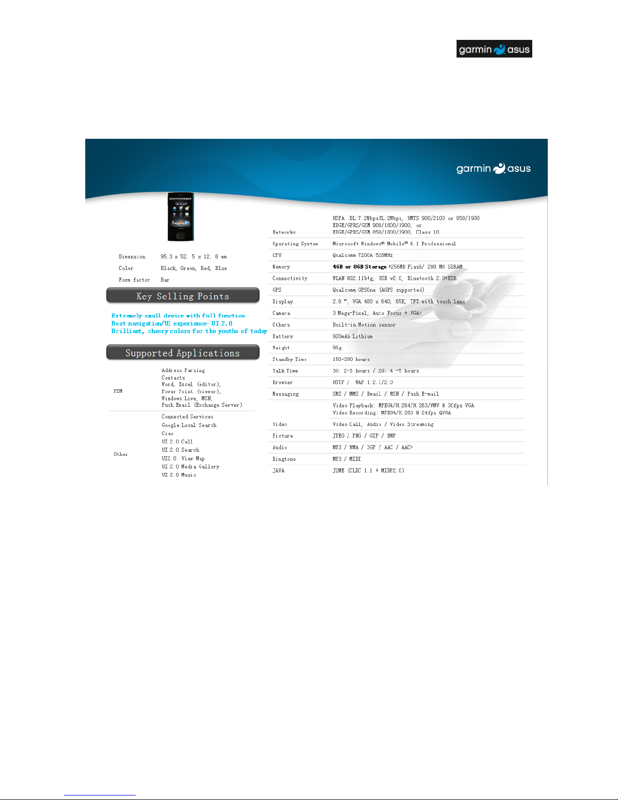
2.3 PRODUCT SPECIFICATION ...............................................................................................................5
3 DISASSEMBLY / ASSEMBLY PROCEDURE ................................................................................6
3.1 INTRODUCTION ...............................................................................................................................6
3.1.1 RECOMMENDED TOOLS..................................................................................................................6
3.2 EXPLODED DIAGRAM ......................................................................................................................7
3.3 DISASSEMBLY PROCEDURE ................................................................................................ .............8
3.4 ASSEMBLY PROCEDURE ................................................................................................................15
4 MMI TESTING ...............................................................................................................................22
TSD ■ Service Manual
V1.0
3
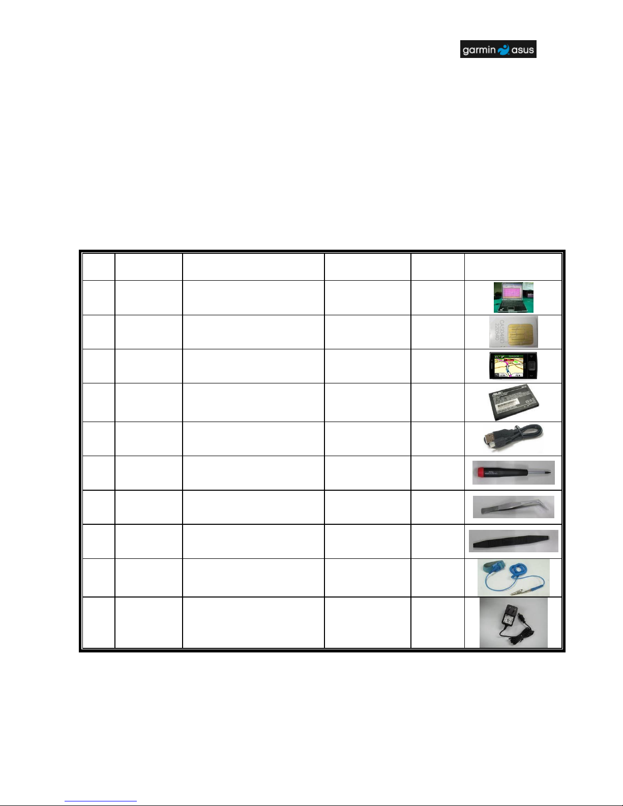
1 Equipment Need
NO#
Equipment
Description
Garmin ASUS Part#
Supplier
Quantity
Remarks
1
Computer
None
None
1
2
Enabled SIM
Card
None
None
1
3
NÜVIFONE
M20
80AM-S01500
Garmin Asus
1
4
Battery
07G01679345
Garmin Asus
1
5
USB
download
cable
14G000502010
Garmin Asus
1
6
Screwdriver
(T5)
None
None
1 7
Tweezers
None
None
1
8
Plastic
Blade
None
None
1
9
ESD Static
Strap
None
None
1
10
ADAPTER
04G267016301
Garmin Asus
1
TSD ■ Service Manual
V1.0
4
2 Introduction
2.1 About This Service Manual
Using this service manual and the suggestions contained in it assures proper installation,
operation, and maintenance of the NÜVIFONE M20. This manual aids service personnel in
testing and repairing NÜVIFONE M20. Service personnel should be familiar with electronic
assembly, testing, and troubleshooting methods.
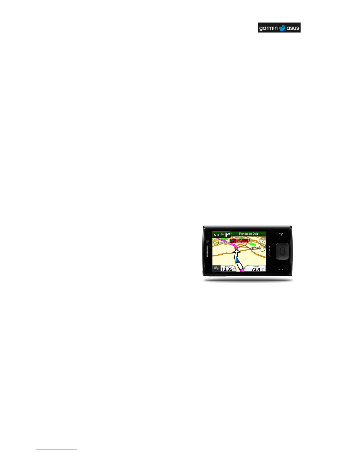
2.2 Overview
M20 is designed for the young generation who enjoys
fun interaction and social connections.
The asymmetrical shape is emphasized by bright,
youthful color. The main body is a simple black, with
only matte finish texture for the hand to recognize
navigation and keys.
All function keys are incorporated on the opposite side
in a metallic strip in order not to interfere with the
general image.
TSD ■ Service Manual
V1.0
5
2.3 Product Specification
TSD ■ Service Manual
V1.0
6
3 Disassembly / Assembly Procedure
3.1 Introduction
This section describes how to disassemble NÜVIFONE M20. Many of the electronic components
used in this phone are vulnerable to damage due to static discharge. Ensure adequate static
protection is in place when handling, shipping, and servicing any internal components.
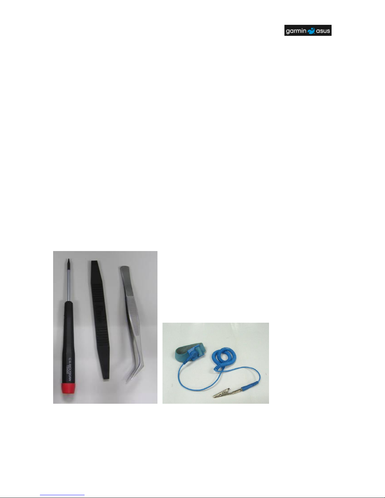
3.1.1 Recommended Tools
� Torque Screw Driver (T5 type, torque is set to 1.2kg-cm)
� Tweezers
� Plastic blade
� ESD Static Strap
TSD ■ Service Manual
V1.0
7
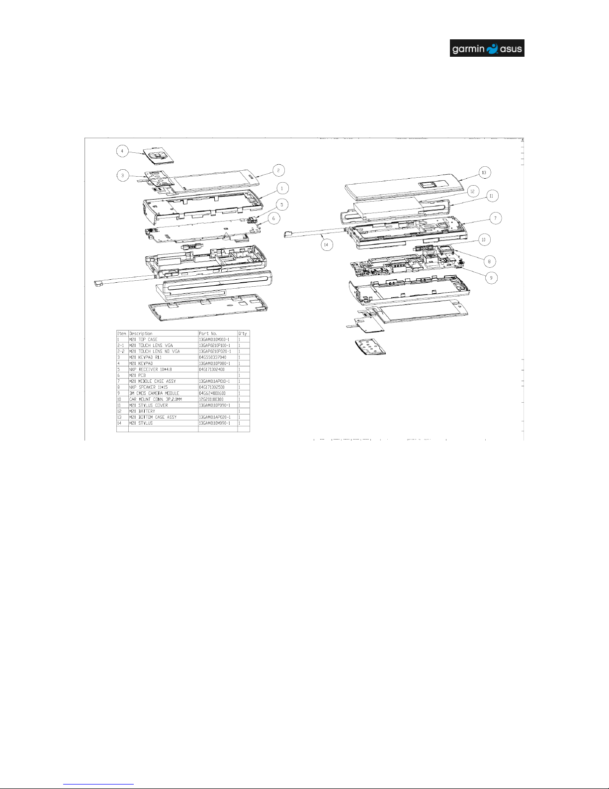
3.2 Exploded Diagram
(If this picture cannot be viewed clearly, please zoom in this page.)
TSD ■ Service Manual
V1.0
8
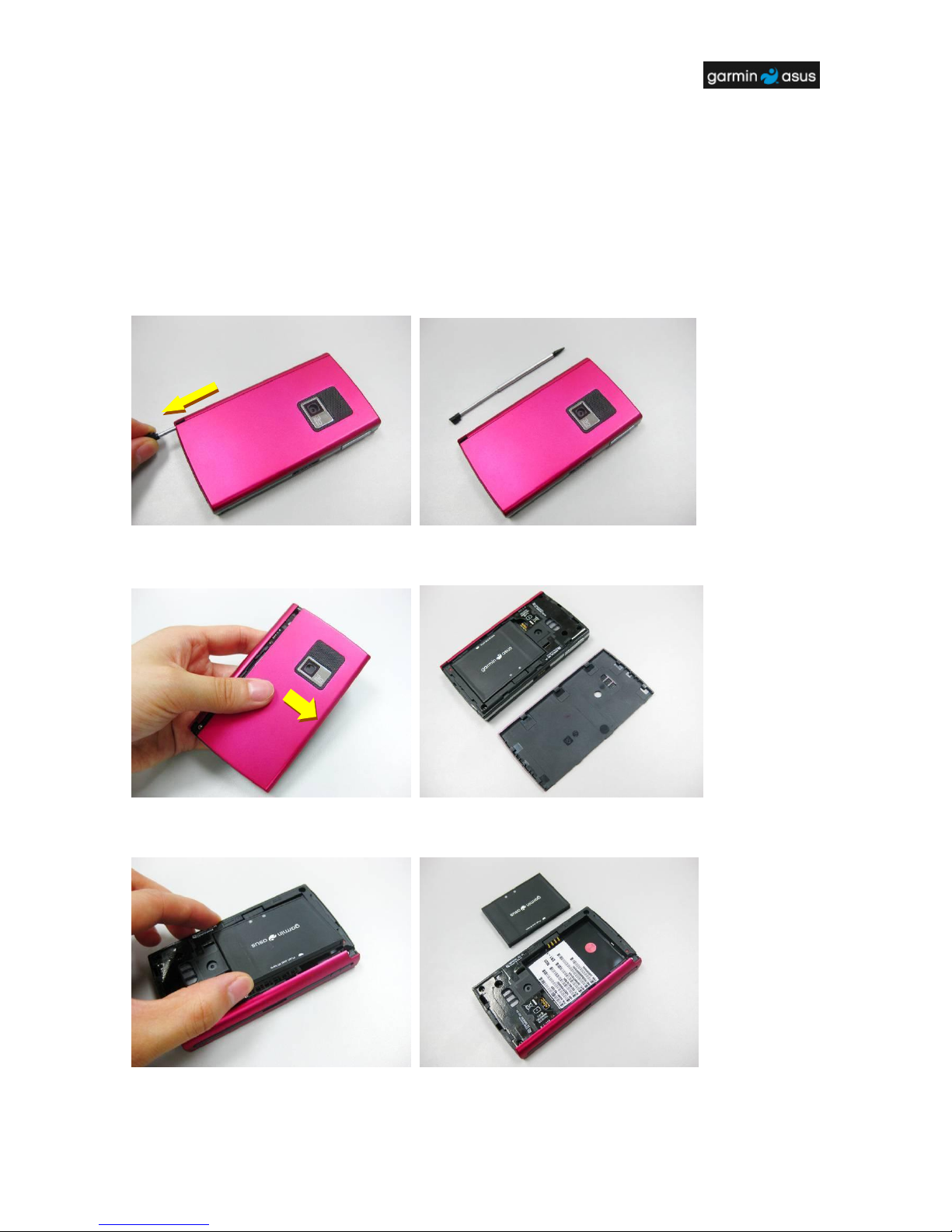
3.3 Disassembly Procedure
The following set of diagrams will demonstrate the correct sequence and action to disassemble
NÜVIFONE M20.
Step 1
Remove the stylus (PN: 13GAM0110M090-1).
Step 2
Push and remove the bottom case away (PN: 13GAM012AP010-1).
Step 3
Take away the battery (PN: 07G016793450).
1 2 2 1 1 1 2
TSD ■ Service Manual
V1.0
9
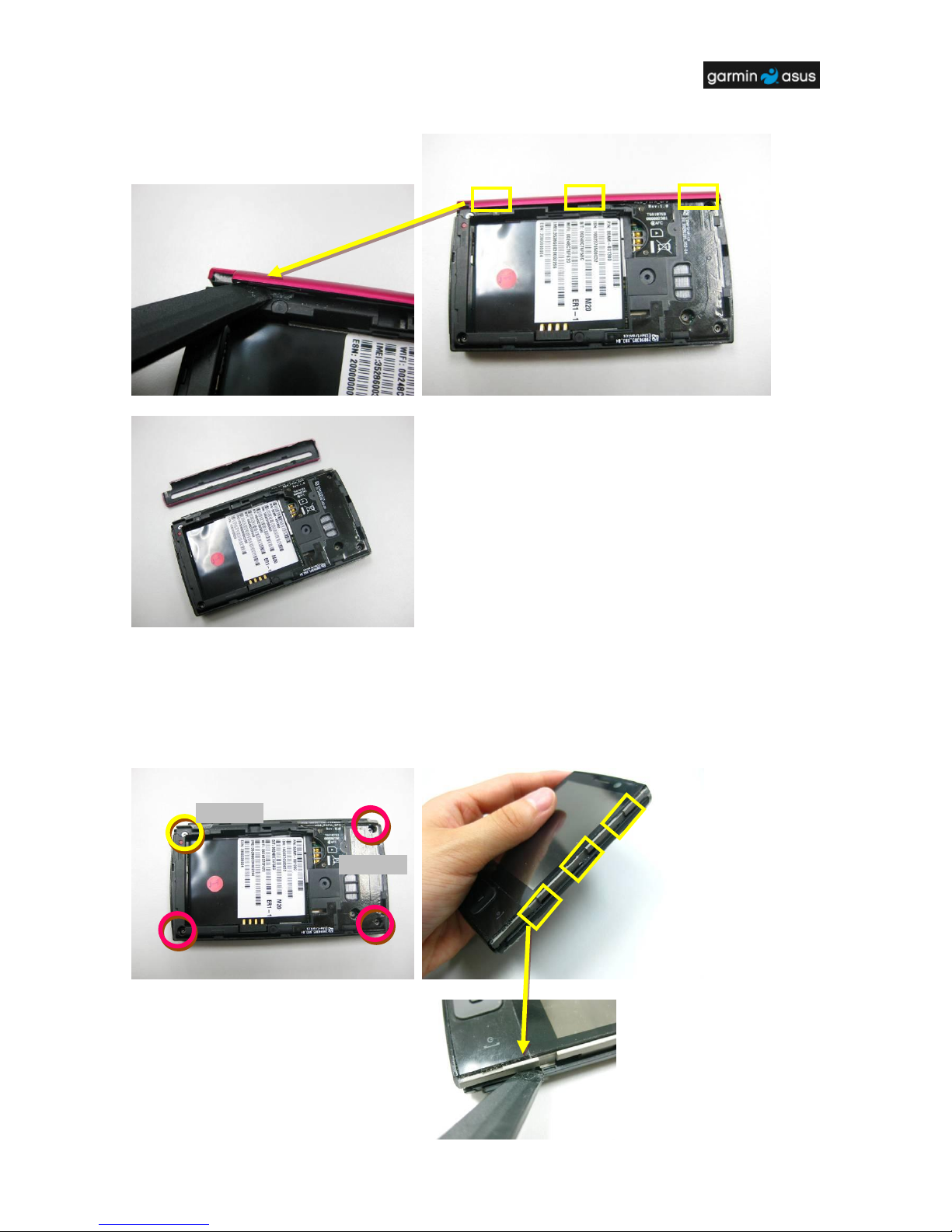
Step 4
Pry the hooks on the stylus cover (PN: 13GAM0120P020-1) and remove it.
Step 5
Remove 4 screws (PN: 13GMBK0K060B SCREW M1.6*6L X 3, T5Screw Driver;
13GMBK0K050W SCREW M1.6*5L X 1, T5 Screw Driver) on the middle case assy
(13GAM011AP010-1). Pry the right side and the top side of the middle case assy to release it
from the hooks by a plastic blade. Then separate the middle case from the module.
M1.6*6L
M1.6*5L
1 2 2
1
 Loading...