


BC™ 20 Wireless Backup Camera Installation Instructions.............................................................. 2
BC™ 20 Wireless Backup Camera Installation Instructions.............................................................. 4
BC™ 20 Wireless Backup Camera Installation Instructions.............................................................. 7
BC™ 20 Wireless Backup Camera Installation Instructions............................................................ 10
BC™ 20 Wireless Backup Camera Installation Instructions............................................................ 13
BC™ 20 Wireless Backup Camera Installation Instructions............................................................ 16
BC™ 20 Wireless Backup Camera Installation Instructions............................................................ 19
BC™ 20 Wireless Backup Camera Installation Instructions............................................................ 22
BC™ 20 Wireless Backup Camera Installation Instructions............................................................ 25
BC™ 20 Wireless Backup Camera Installation Instructions............................................................ 28
BC™ 20 Wireless Backup Camera Installation Instructions............................................................ 31
BC™ 20 Wireless Backup Camera Installation Instructions............................................................ 34
Garmin International, Inc.
1200 East 151st Street
Olathe, Kansas 66062, USA
Garmin (Europe) Ltd.
Liberty House, Hounsdown Business Park
Southampton, Hampshire, SO40 9LR UK
Garmin Corporation
No. 68, Zhangshu 2nd Road, Xizhi Dist.
New Taipei City, 221, Taiwan (R.O.C.)
December 2013 190-01600-90_0D Printed in Taiwan
Garmin® and the Garmin logo are trademarks of Garmin Ltd. or its subsidiaries, registered in the USA and other countries. BC™ is a
trademark of Garmin Ltd. or its subsidiaries. These trademarks may not be used without the express permission of Garmin.
BC™ 20 Wireless Backup Camera
Installation Instructions
WARNING
See the Important Safety and Product Information guide in the
GPS device product box for product warnings and other
important information.
Garmin® strongly recommends having an experienced installer
with the proper knowledge of electrical systems install the
device. Incorrectly wiring the power cable can result in damage
to the vehicle or the battery and can cause bodily injury.
When connecting the power cable, do not remove the in-line
fuse holder. To prevent the possibility of injury or product
damage caused by fire or overheating, the appropriate fuse
must be in place as indicated in the product specifications. In
addition, connecting the power cable without the appropriate
fuse in place will void the product warranty.
CAUTION
Always wear safety goggles, ear protection, and a dust mask
when drilling, cutting, or sanding.
NOTICE
When drilling or cutting, always check what is on the opposite
side of the surface.
These installation instructions do not apply to a specific vehicle
type, and are meant as a guide when installing this product on
your vehicle. For questions specific to your vehicle, you should
contact the vehicle manufacturer.
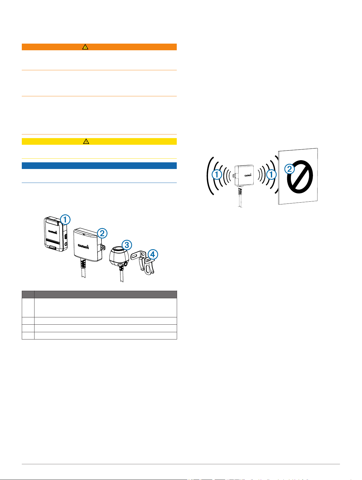
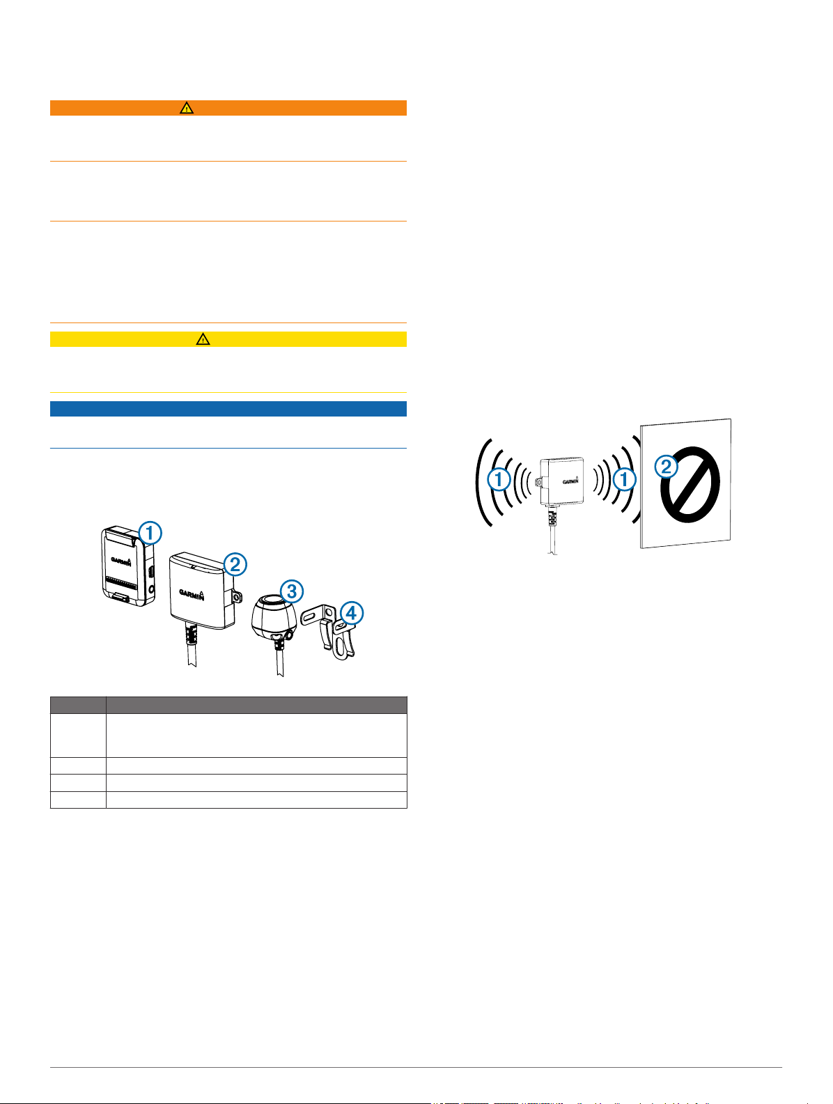
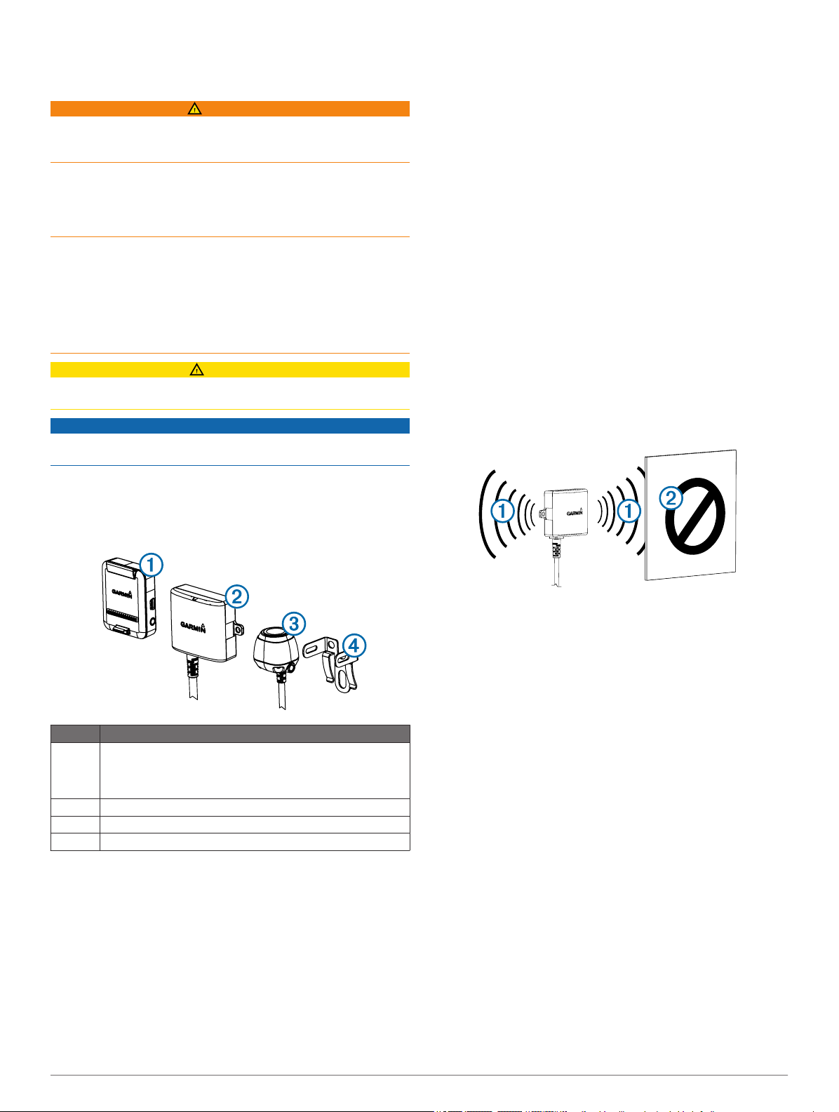
Item Description
Wireless camera PND mount
À
The PND device must be powered through this mount to
communicate with the camera.
Transmitter
Á
Camera
Â
Camera mounting bracket
Ã
Tools Needed
• Drill and 0.36 in. (9.09 mm, or size T) drill bit
• #2 Phillips screwdriver
• Screws, bolts, or cable ties (to secure the transmitter)
• Solderless wire-splice connector or solder and heat-shrink
tubing
• RV sealant (optional)
Camera Mounting Considerations
When selecting a location to mount the camera, observe these
considerations.
• You should test a mounting location before you permanently
mount the camera.
• Installing the camera higher on the back of the vehicle
provides a better viewing angle.
• The included bracket can be clipped onto a license plate or
other similar surface, or it can be fastened to the back of the
vehicle using the included self-tapping, panhead screws.
Transmitter Location and Wiring Considerations
When selecting a location to install the wireless transmitter,
observe these considerations.
• You should test a proposed installation location before you
permanently install the transmitter.
• Although the transmitter can reliably transmit the video signal
over approximately 45 ft. (13.5 m), the location of the
transmitter can affect this range.
◦ The closer you install the transmitter to the wireless
camera PND mount, the more reliable the signal.
◦ The transmitter provides the best signal when either flat
surface À is pointing toward the wireless camera PND
mount.
◦ Dense metal or appliances Á in the path of the transmitter
greatly reduce the transmission distance.
◦ The fewer solid objects that exist between the path of the
transmitter and the device, the more reliable the signal.
• If the distance between the camera and the transmitter
exceeds the length of the included cable, additional
extension cables can be used. A 50 ft. (15 m) extension
cable can be purchased, and more than one extension cable
can be installed. See your Garmin dealer or go to
www.garmin.com for more information.
• The fuse holder located near the transmitter is not
waterproof. Installing the fuse holder in a location that is
exposed to the elements is not recommended.
• The connector between the camera and the transmitter is not
waterproof. If you make this connection in a location exposed
to the elements, you must make sure that the connection is
waterproof.
Testing the Camera and Transmitter Location
Temporarily secure the camera in the preferred mounting
1
location.
Temporarily place the transmitter in the preferred installation
2
location, and connect it to power and to the camera.
TIP: If you do not want to splice into the wiring of your
vehicle for this test, you can connect the transmitter and
camera to a 12 Vdc battery.
Test the transmitter for correct operation by applying power
3
to the PND device using the wireless camera PND mount.
If you do not see video on the device at the preferred
installation location, move the transmitter to another location
and test it again.
Repeat steps 2–3 until the transmitter operates correctly.
4
Test the camera view by observing the video on the device.
5
If the camera does not provide the optimal view for your
6
vehicle, move it to another location and test it again.
2
Repeat steps 5–6 until the camera mounting location
7
provides the optimal view for your vehicle.
TIP: Make note of which direction is up when you are testing
the camera view to ensure correct permanent installation.
Mounting the Camera
Before you permanently mount the camera, you should test the
mounting location for the optimal view for your vehicle (Testing
the Camera and Transmitter Location).
If you have already connected the camera to the bracket, you
must first disassemble it.
Place the bracket À in the mounting location.
1
Select an option:
2
• If you are mounting the bracket directly on the surface of
your vehicle, mark the locations of the two holes on the
bracket Á.
• If you are installing the bracket on a license plate, remove
one of the license plate screws and clip the bracket in
place so the hole on the bracket  lines up with the hole
on the license plate.
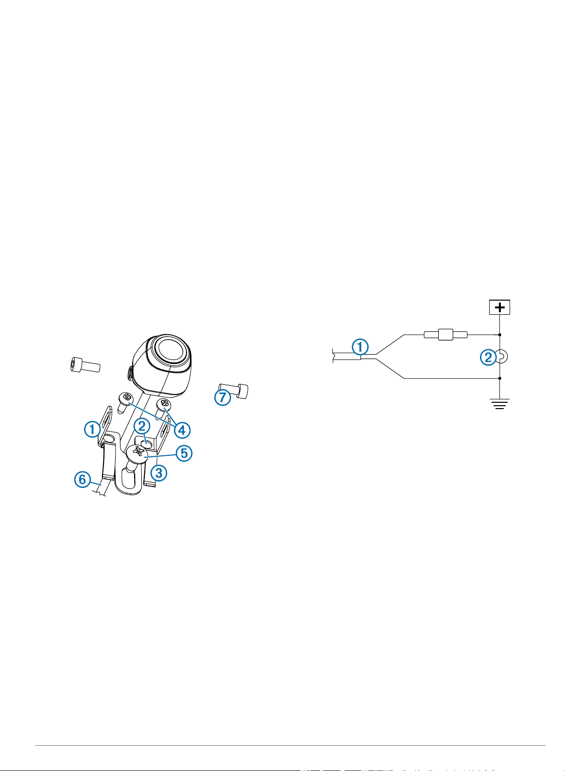
Secure the bracket to the vehicle using either the included
3
self-tapping screws à or the license-plate screw you
removed in step 2 Ä.
Place the camera in the bracket, and determine the best
4
place for the camera cable Å to enter the vehicle.
Using an appropriate drill bit, drill a hole for the camera cable
5
to enter the vehicle.
Feed the camera cable through the hole and route it to the
6
transmitter location.
15 m (50 ft.) extension cables can be purchased separately,
if needed.
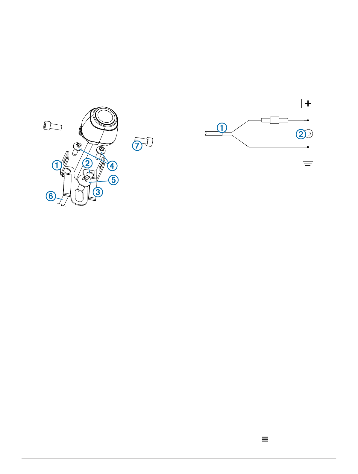
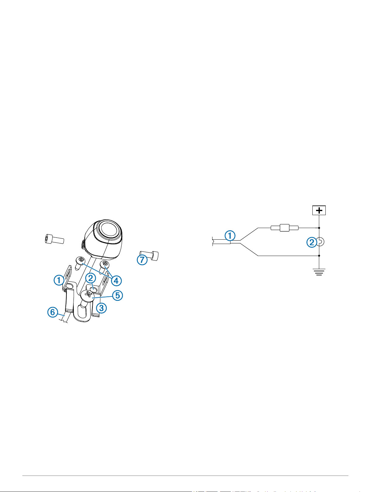
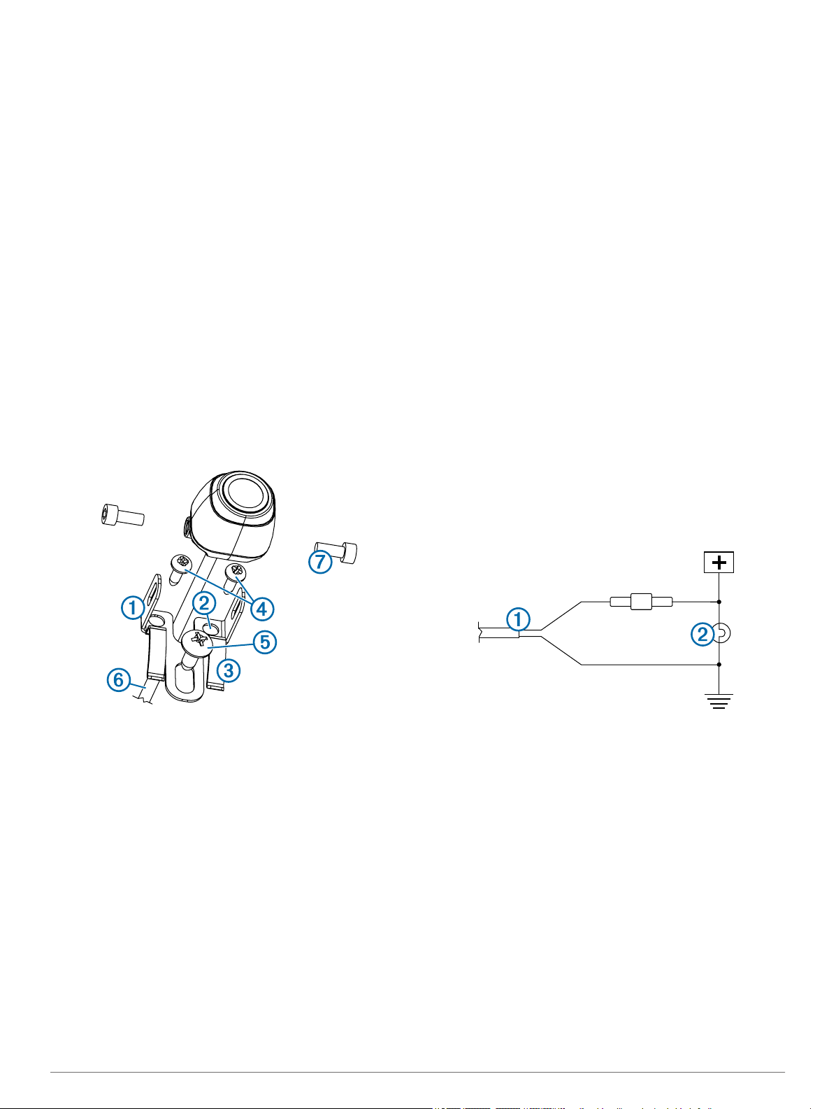
Secure the camera in the bracket using the included hex
7
bolts Æ.
Adjust the angle of the camera and tighten the hex bolts
8
using the included hex key.
Apply RV sealant around the cable where it enters the
9
vehicle (optional).
Installing the Transmitter
Before you permanently install the transmitter, you must test the
installation location for correct operation (Testing the Camera
and Transmitter Location).
Secure the transmitter to the installation location using
1
hardware appropriate for the location, such as screws, bolts,
or cable ties.
The fuse holder located near the transmitter is not
waterproof. Installing the fuse holder in a location that is
exposed to the elements is not recommended.
Connect the camera and transmitter cables.
2
The connector between the camera and the transmitter is not
waterproof. If you make this connection in a location exposed
to the elements, you must make sure that the connection is
waterproof.
Connect the power cable À from the transmitter to a 12–
3
24 VDC power source, preferably a reverse lamp Á, using a
solderless wire-splice connector (not included).
NOTE: Connecting the transmitter to an always-on
12-24 VDC source (such as a running lamp) instead of a
reverse lamp requires you to manually switch power to the
transmitter. The transmitter may drain your vehicle battery if
it is left on.
If you did not use a solderless wire-splice connector, solder
4
and heat-shrink the electrical connections to protect them
from the elements.
Using the Camera
The camera shows video on the device in different ways,
depending on how you connected the power to the transmitter.
Select an option to show video:
1
• If you connected the transmitter to a reverse lamp
(recommended), place the vehicle into reverse. The
device automatically shows video from the backup
camera.
• If you connected the transmitter to a running lamp or other
steady 12 VDC source, select the camera icon on the
device to show video from the backup camera.
Select an option to resume normal device operation:
2
• If you connected the transmitter to a reverse lamp
(recommended), take the vehicle out of reverse. The
device automatically resumes normal operation.
• If you connected the transmitter to a running lamp or other
steady 12 VDC source, select the camera icon on the
device to resume normal operation.
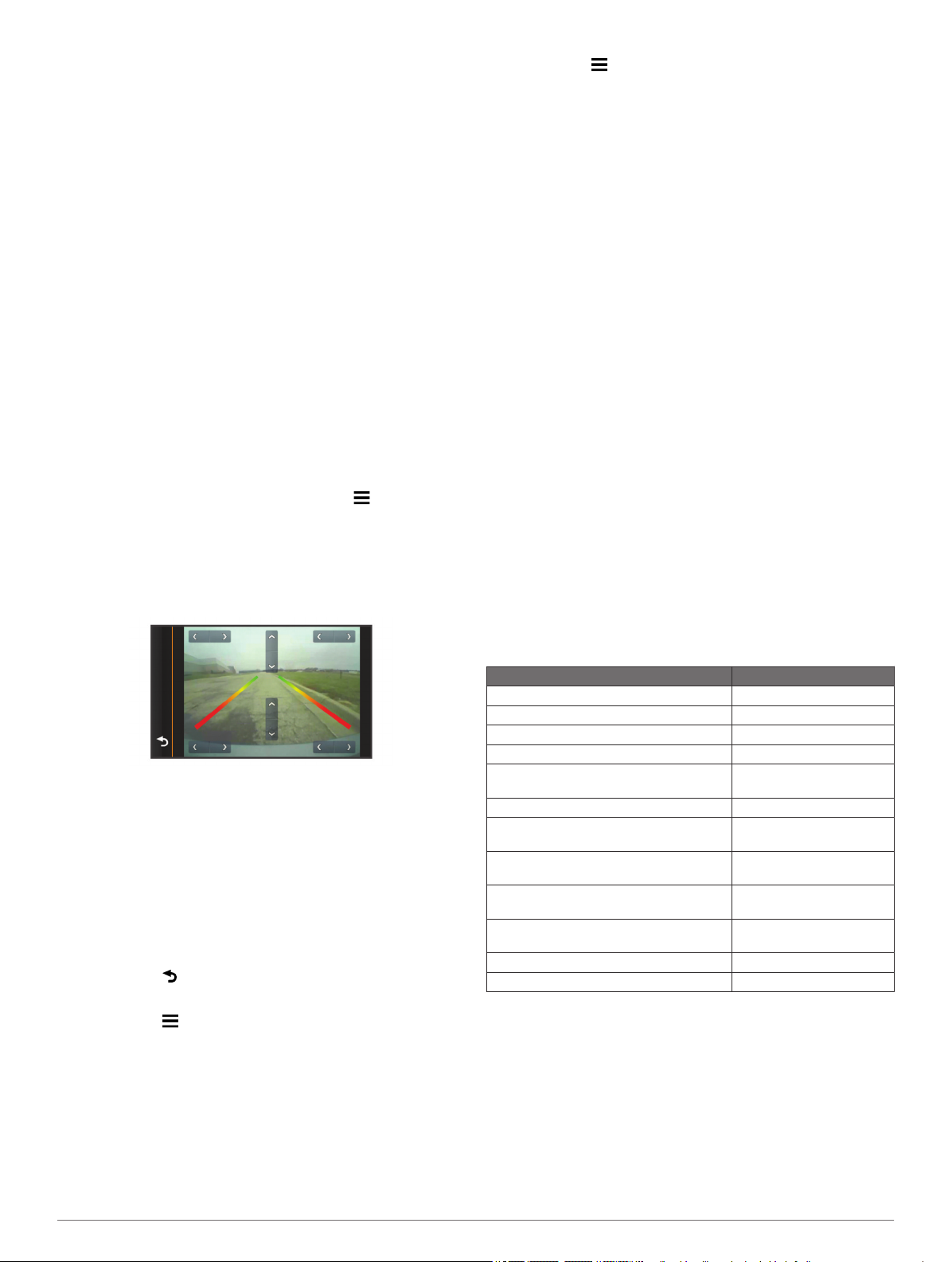
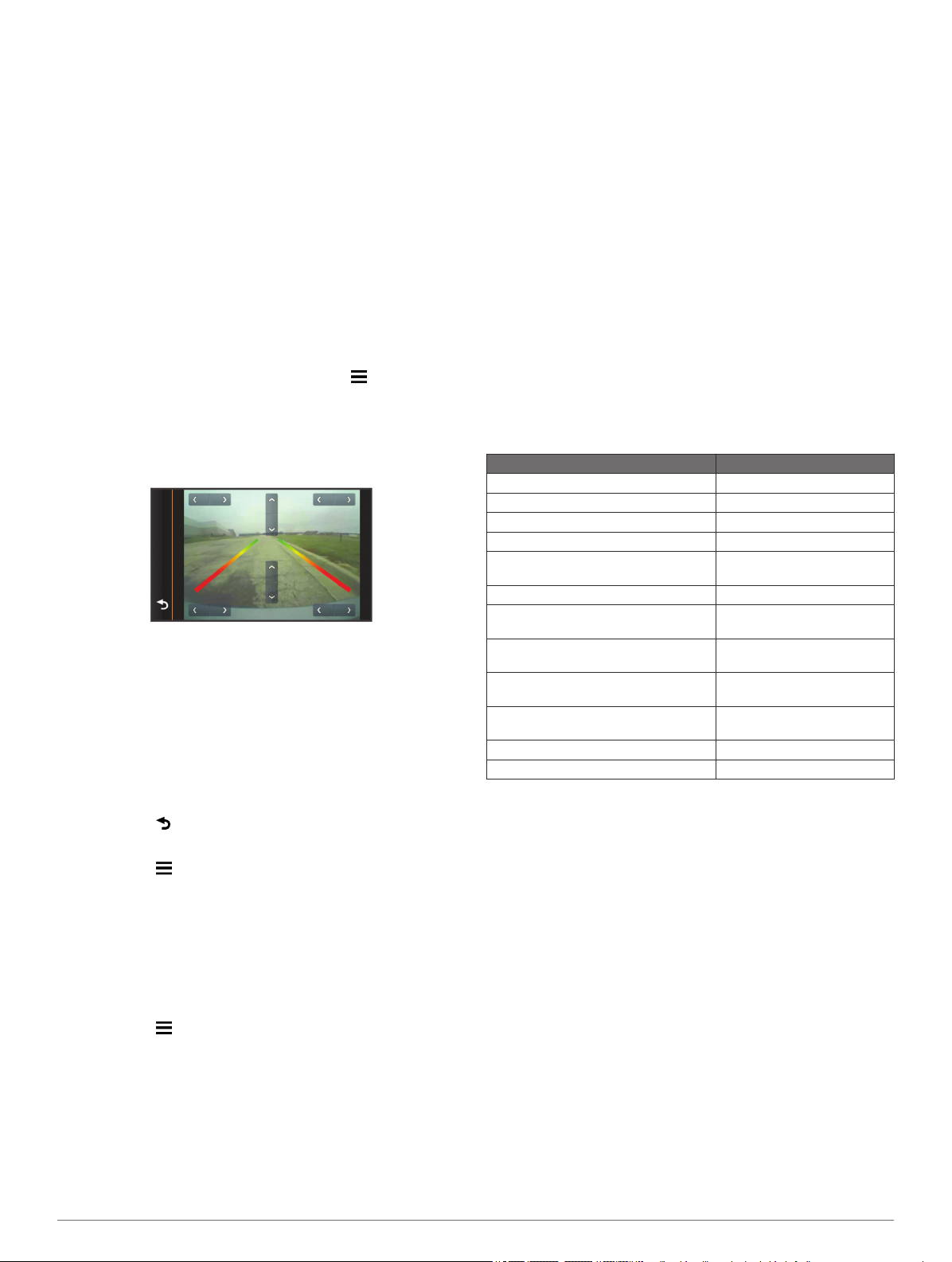
Aligning the Guidance Lines
Guidance lines provide a visual representation of the vehicle's
path when in reverse. For best reference, they should be
aligned to reflect the outside edges of the vehicle.
Position the vehicle with one side closely aligned to a curb,
1
driveway, or parking stall lines.
You may want to position the vehicle in the center of a
parking stall, and then pull forward into the next stall. This
allows you to use the parking stall lines in the rear of the
vehicle as reference points for alignment.
The curb, driveway, or parking stall lines should be clearly
visible on the device.
From the camera view, select > Adjust.
2
3
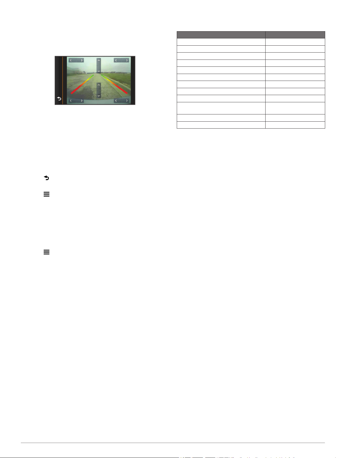
Use the arrows in the corners of the screen to move the
3
guidance lines to match the angle and position of the curb,
driveway, or parking stall lines.
The guidance lines should appear directly on top of your
reference points.
Use the arrows in the center of the screen to move the
4
guidance lines up or down.
The red section of the guidance lines should be aligned with
the rear of your vehicle.
If necessary, reposition the vehicle with the other side closely
5
aligned to a curb, driveway, or parking stall lines, and repeat
the alignment process.
You should attempt to keep the guidance lines symmetrical,
even if your vehicle is not in perfect alignment with the curb,
driveway, or parking stall lines.
Select when alignment is complete.
6
Showing or Hiding Guidance Lines
Select .
1
Select an option:
2
• To show the guidance lines on the screen, select Show
Lines.
• To hide the guidance lines on the screen, select Hide
Lines.
Restoring Alignment
You can reset the guidance lines to their default settings.
Select > Restore.
1
Select Yes.
2
Specifications
Specification Value
Camera sensor 1/3.7-type CMOS
Camera resolution 640 × 480
Camera angle (vertical) 115°
Camera angle (horizontal) 140°
Camera and transmitter input voltage 9–28 VDC
Fuse 500 mA, fast-blow
Camera and transmitter current usage 150 mA @ 12 VDC
Camera and transmitter waterproof rating IEC 60529 IPX7
Camera temperature range -40° to 185°F (-40° to 85°C)
Transmitter and PND mount temperature
range
Wireless transmission type 2.4 GHz ISM radio band
Wireless transmission distance 45 ft. (13.5 m)
-4° to 158°F (-20° to 70°C)
Pairing the Transmitter and Device Mount
The transmitter and wireless camera PND mount come paired
from the factory. If the transmitter and the PND mount are
properly installed and you are not receiving video, you can try to
re-pair the transmitter and the PND mount.
Verify there is no power to the transmitter by placing the
1
vehicle in park or turning off the applicable steady power
source.
Turn on the PND device connected to the wireless camera
2
PND mount.
On the wireless camera PND mount, hold PAIR until Start
3
Pairing appears on the PND device.
If Start Pairing does not appear on the PND device, make
sure the wireless camera PND mount is correctly connected
to power.
Apply power to the transmitter by placing the vehicle in
4
reverse or turning on the applicable steady power source.
After approximately five seconds, Pairing OK appears on
the PND device.
Power cycle both the wireless camera PND mount and the
5
transmitter by turning them both off and then back on again.
If the transmitter and wireless camera PND device mount do
6
not pair successfully, repeat steps 1–4.
4

BC™ 20 Wireless Backup Camera
Installation Instructions
AVERTISSEMENT
Consultez le guide Informations importantes sur le produit et la
sécurité inclus dans l'emballage du GPS pour prendre
connaissance des avertissements et autres informations sur le
produit.
Garmin vous recommande fortement de faire installer l'appareil
par un technicien expérimenté, disposant des connaissances
appropriées en matière de circuits électriques. Le raccordement
incorrect du câble d'alimentation peut endommager le véhicule
ou la batterie et entraîner des blessures corporelles.
Lorsque vous connectez le câble d'alimentation, ne retirez pas
le porte-fusible en ligne. Pour éviter de vous blesser ou
d'endommager votre produit en exposant la batterie au feu ou à
une chaleur extrême, le fusible approprié doit être placé comme
indiqué dans les caractéristiques techniques du produit. De
plus, la connexion du câble d'alimentation en l'absence du
fusible approprié annulerait la garantie du produit.
ATTENTION
Portez toujours des lunettes de protection, un équipement
antibruit et un masque anti-poussière lorsque vous percez,
coupez ou poncez.
AVIS
Lorsque vous percez ou coupez, commencez toujours par
vérifier la nature de la face opposée de l'élément.
• Testez un emplacement de montage avant d'installer la
caméra de manière définitive.
• Installez la caméra en hauteur à l'arrière du véhicule pour
bénéficier d'un angle de vue optimal.
• Le support de fixation fourni peut être clipsé à une plaque
d'immatriculation ou à un support similaire, ou bien attaché à
l'arrière du véhicule à l'aide des vis à tête cylindrique plate
autoperceuses fournies.
Emplacement de l'émetteur et considérations relatives au câblage
Au moment de choisir un emplacement d'installation de
l'émetteur sans fil, tenez compte des remarques suivantes.
• Testez l'emplacement d'installation proposé avant d'installer
l'émetteur de manière définitive.
• Bien que l'émetteur puisse transmettre de manière fiable le
signal vidéo à une distance de 13,5 m (45 pieds) environ,
l'emplacement de l'émetteur peut affecter cette portée.
◦ La fiabilité du signal dépend de la proximité de l'émetteur
par rapport au support de l'appareil de navigation avec
caméra sans fil.
◦ L'émetteur restitue un signal optimal quand il est posé sur
une surface plane À orientée vers le support de l'appareil
de navigation avec caméra sans fil.
Ces instructions d'installation sont universelles et se proposent
d'accompagner l'installation du produit sur votre véhicule, quel
que soit son modèle. Pour toutes questions sur votre véhicule,
veuillez contacter votre concessionnaire.
Elément Description
À
Á
Â
Ã
Support de l'appareil de navigation avec caméra sans fil
L'appareil de navigation doit être alimenté via ce support afin
de communiquer avec la caméra.
Emetteur
Caméra
Support de fixation de la caméra
Outils requis
• Perceuse et foret de 9,09 mm ou taille T (0,36 pouce)
• Tournevis cruciforme numéro 2
• Vis, écrous ou attaches de câbles (pour fixer l'émetteur)
• Clip pour câbles ne nécessitant pas de soudure ou fer à
souder et tube thermorétrécissable
• Mastic adapté aux véhicules de loisir (facultatif)
Considérations relatives au montage de la caméra
Au moment de choisir un emplacement de montage de la
caméra, tenez compte des remarques suivantes.
◦ La présence de métal dense ou d'autres appareils Á sur
le chemin emprunté par l'émetteur dégrade
considérablement la distance de transmission.
◦ Pour obtenir un signal fiable, évitez au maximum la
présence d'obstacles sur le chemin emprunté par
l'émetteur jusqu'à l'appareil.
• Si la distance qui sépare la caméra de l'émetteur dépasse la
longueur du câble fourni, vous pouvez utiliser des câbles
d'extension. Il est possible d'acheter un câble d'extension de
15 m (50 pieds) et d'installer plusieurs câbles d'extension.
Contactez votre revendeur Garmin ou visitez le site
www.garmin.com pour obtenir plus d'informations.
• Le porte-fusible situé près de l'émetteur n'est pas étanche. Il
n'est pas recommandé d'installer le porte-fusible à un
emplacement non protégé des éléments extérieurs.
• Le connecteur entre la caméra et l'émetteur n'est pas
étanche. Si vous effectuez le branchement à un
emplacement non protégé des éléments extérieurs, vous
devez vous assurer que la connexion est étanche.
Test de l'emplacement de la caméra et de l'émetteur
Installez la caméra de manière temporaire à l'emplacement
1
de votre choix.
Placez l'émetteur de manière temporaire à l'emplacement de
2
votre choix et reliez-le à l'alimentation ainsi qu’à la caméra.
ASTUCE : si vous ne souhaitez pas vous raccorder à votre
véhicule pour ce test, vous pouvez relier l'émetteur et la
caméra à une batterie de 12 V c.c.
5
Vérifiez le bon fonctionnement de l´émetteur en alimentant
3
l'appareil de navigation avec le support de l'appareil de
navigation avec caméra sans fil.
Si le flux vidéo n'apparaît pas sur l'appareil à votre
emplacement d'installation préféré, déplacez l'émetteur et
réalisez un autre test.
Répétez les étapes 2 et 3 tant que l'émetteur ne fonctionne
4
pas correctement.
Testez l'angle de vue de la caméra en observant la vidéo sur
5
l'appareil.
Si la caméra ne fournit pas un angle de vue optimal pour
6
votre véhicule, déplacez-la et réalisez un autre test.
Répétez les étapes 5 et 6 jusqu'à trouver un emplacement
7
d'installation qui offre un angle de vue optimal pour votre
véhicule.
ASTUCE : quand vous testez l'angle de vue de la caméra,
prenez note de la direction vers le haut pour ne pas vous
tromper lorsque vous l'installerez de manière définitive.
Montage de la caméra
Avant d'installer la caméra de manière définitive, testez
l'emplacement de montage pour obtenir l'angle de vue optimal
suivant votre véhicule (Test de l'emplacement de la caméra et
de l'émetteur).
Si vous avez déjà relié la caméra au support de fixation,
commencez par la démonter.
Placez le support de fixation À à l'emplacement
1
d'installation.
Fixez bien la caméra dans le support à l'aide des écrous
7
hexagonaux fournis Æ.
Ajustez l'angle de la caméra et serrez les écrous
8
hexagonaux à l'aide de la clé Allen fournie.
Appliquez du mastic adapté aux véhicules de loisir (facultatif)
9
autour du câble, à son point d'entrée dans le véhicule.
Installation de l'émetteur
Avant d'installer l'émetteur de manière définitive, veuillez vérifier
son bon fonctionnement à cet emplacement (Test de
l'emplacement de la caméra et de l'émetteur).
Lors de l'installation de l'émetteur, veuillez utiliser un matériel
1
adapté à cet emplacement, comme des vis, des écrous ou
des attaches de câbles.
Le porte-fusible situé près de l'émetteur n'est pas étanche. Il
n'est pas recommandé d'installer le porte-fusible à un
emplacement non protégé des éléments extérieurs.
Reliez la caméra aux câbles de l'émetteur.
2
Le connecteur entre la caméra et l'émetteur n'est pas
étanche. Si vous effectuez le branchement à un
emplacement non protégé des éléments extérieurs, vous
devez vous assurer que la connexion est étanche.
Reliez le câble d'alimentation À de l'émetteur à une source
3
d'alimentation de 12–24 V c.c., de préférence aux feux de
marche arrière Á, à l'aide d'un clip pour câbles ne
nécessitant pas de soudure (non fourni).
Sélectionnez une option :
2
• Si vous montez le support à même le véhicule, marquez
les emplacements des deux trous sur le support Á.
• Si vous installez le support sur une plaque
d'immatriculation, retirez l'une des vis de la plaque
d'immatriculation et clipsez le support à l'emplacement
prévu de sorte que le trou du support  soit aligné avec le
trou de la plaque d'immatriculation.
Fixez le support au véhicule à l'aide des vis autoperceuses
3
ou de la vis de la plaque d'immatriculation que vous avez
Ã
retirée à l'étape 2 Ä.
Placez la caméra dans le support de fixation et trouvez le
4
meilleur endroit pour faire passer le câble de la caméra
dans le véhicule.
A l'aide d'un foret adapté, percez un trou afin de faire passer
5
le câble de la caméra dans le véhicule.
Faites passer le câble de la caméra dans le trou et
6
acheminez-le jusqu'à l'emplacement de l'émetteur.
Des extensions de câble de 15 m (50 pieds) sont disponibles
à la vente, au besoin.
Å
REMARQUE : si vous reliez l'émetteur à une source
d'alimentation permanente de 12-24 V c.c. (aux feux de
circulation, par exemple) et non pas aux feux de marche
arrière, vous devrez allumer et éteindre l'émetteur
manuellement. Si vous le laissez allumé en permanence,
l'émetteur risque de décharger la batterie de votre véhicule.
Si vous n'avez pas utilisé un clip pour câbles ne nécessitant
4
pas de soudure, soudez les connexions électriques et
utilisez le tube thermorétrécissable pour les protéger des
éléments extérieurs.
Utilisation de la caméra
Suivant la façon dont vous aurez relié l'alimentation à
l'émetteur, la caméra affichera un signal vidéo sur l'appareil de
différentes façons.
Sélectionnez une option d'affichage vidéo :
1
• Si vous avez relié l'émetteur à un feu de marche arrière
(recommandé), passez en marche arrière. L'appareil
diffuse automatiquement la vidéo depuis la caméra de
recul.
• Si vous avez relié l'émetteur à un feu de circulation ou à
une autre source d'alimentation stable de 12 V c.c.,
sélectionnez l'icône de caméra sur l'appareil pour diffuser
la vidéo depuis la caméra de recul.
6
Sélectionnez une option pour rétablir le fonctionnement
2
normal de l'appareil :
• Si vous avez relié l'émetteur à un feu de recul
(recommandé), sortez de la marche arrière. L'appareil
fonctionne à nouveau normalement et ce,
automatiquement.
• Si vous avez relié l'émetteur à un feu de circulation ou à
une autre source d'alimentation stable de 12 V c.c.,
sélectionnez l'icône de caméra sur l'appareil pour qu'il
fonctionne à nouveau normalement.
Alignement des lignes de guidage
Les lignes de guidage vous permettent de visualiser la
trajectoire du véhicule quand vous effectuez une marche
arrière. Pour une utilisation optimale, elles doivent être alignées
de façon à représenter les bords extérieurs du véhicule.
Stationnez votre véhicule en alignant étroitement un côté à
1
un trottoir, une allée ou les lignes d'une place de parking.
Vous pouvez aussi stationner le véhicule au centre d'une
place de parking puis avancer jusqu'à la place devant vous.
Cela vous permet d'utiliser les lignes de la place de parking à
l'arrière du véhicule comme points de référence pour
l'alignement.
Le trottoir, l'allée ou les lignes de la place de parking doivent
apparaître de manière claire sur l'appareil.
A partir de l'affichage caméra, sélectionnez > Régler.
2
Utilisez les flèches dans les angles de l'écran pour déplacer
3
les lignes de guidage afin de les faire coïncider avec l'angle
et la position du trottoir, de l'allée ou des lignes de la place
de parking.
Les lignes de guidage doivent apparaître directement en
haut de vos points de référence.
Sélectionnez > Restaurer.
1
Sélectionnez Oui.
2
Couplage de l'émetteur et du support de l'appareil
L'émetteur et le support de l'appareil de navigation avec caméra
sans fil sont couplés selon les réglages d'usine. Si l'émetteur et
le support de l'appareil de navigation sont correctement installés
et si vous ne recevez pas de signal vidéo, vous pouvez essayer
de recoupler l'émetteur et le support de l'appareil de navigation.
Assurez-vous que l'alimentation est coupée du côté de
1
l'émetteur en mettant votre véhicule au point mort ou en
désactivant la source d'alimentation stable, le cas échéant.
Allumez l'appareil de navigation connecté au support de
2
l'appareil de navigation avec caméra sans fil.
Sur le support de l'appareil de navigation avec caméra sans
3
fil, maintenez enfoncée la touche PAIR pour faire apparaître
le message Démarrage du couplage sur l'appareil de
navigation.
Si le message Démarrage du couplage ne s'affiche pas sur
l'appareil de navigation, vérifiez que le support de l'appareil
de navigation avec caméra sans fil est bien relié à
l'alimentation.
Passez en marche arrière ou activez la source d'alimentation
4
stable, le cas échéant, pour alimenter l'émetteur.
Au bout de cinq secondes environ, le message Couplage
OK apparaît à l'écran de l'appareil de navigation.
Eteignez et rallumez le support de l'appareil de navigation
5
avec caméra sans fil et l'émetteur.
Si l'émetteur et le support de l'appareil de navigation avec
6
caméra sans fil n'ont pas été couplés, répétez les étapes 1 à
4.
Utilisez les flèches au centre de l'écran pour déplacer les
4
lignes de guidage vers le haut ou vers le bas.
La partie rouge des lignes de guidage doit être alignée avec
l'arrière de votre véhicule.
Si besoin, restationnez le véhicule en alignant étroitement
5
l'autre côté à un trottoir, une allée ou les lignes d'une place
de parking, et répétez la procédure d'alignement.
Dans la mesure du possible, faites en sorte que les lignes de
guidage soient symétriques, même si votre véhicule n'est
pas parfaitement aligné avec le trottoir, l'allée ou les lignes
de la place de parking.
Sélectionnez à la fin de l'alignement.
6
Affichage ou masquage des lignes de guidage
Sélectionnez .
1
Sélectionnez une option :
2
• Pour afficher les lignes de guidage à l'écran, sélectionnez
Afficher les lignes.
• Pour masquer les lignes de guidage à l'écran,
sélectionnez Masquer les lignes.
Restauration de l'alignement
Vous pouvez restaurer les paramètres par défaut des lignes de
guidage.
Caractéristiques techniques
Caractéristique Valeur
Capteur de la caméra 1/3,7-type CMOS
Résolution de la caméra 640 × 480
Angle de la caméra (vertical) 115°
Angle de la caméra (horizontal) 140°
Tension d'entrée de la caméra et de
l'émetteur
Fusible 500 mA, à fusion rapide
Consommation de courant de la caméra
et de l'émetteur
Indice d'étanchéité de la caméra et de
l'émetteur
Plage de températures de la caméra De -40 °C à 85 °C (de
Plages de températures de l'émetteur et
du support de l'appareil de navigation
Type de transmission sans fil Bande radio ISM 2,4 GHz
Distance de transmission sans fil 13,5 m (45 pieds)
9–28 V c.c.
150 mA à 12 V c.c.
IPX7 CEI 60529
-40 °F à 185 °F)
De -20 °C à 70 °C (de
-4 °F à 158 °F)
7
BC™ 20 Wireless Backup Camera
Installation Instructions
ATTENZIONE
Per avvisi sul prodotto e altre informazioni importanti, consultare
la guida Informazioni importanti sulla sicurezza e sul prodotto
inclusa nella confezione del dispositivo GPS.
Garmin consiglia di far installare il dispositivo esclusivamente
da tecnici esperti e qualificati. Il collegamento errato del cavo di
alimentazione potrebbe provocare danni al prodotto o alla
batteria, nonché lesioni alla persona.
Quando si collega il cavo di alimentazione, non rimuovere il
portafusibili. Per evitare possibili lesioni o danni al prodotto
dovuti a incendio o surriscaldamento, è necessario che il
fusibile appropriato sia installato come indicato nelle specifiche
del prodotto. Inoltre, il collegamento del cavo di alimentazione
senza che sia installato il fusibile appropriato invaliderà la
garanzia del prodotto.
AVVISO
Durante le operazioni di foratura, taglio o carteggiatura,
indossare degli occhiali protettivi, una maschera antipolvere e
un'adeguata protezione per l'udito.
AVVERTENZA
Prima di effettuare fori o tagli verificare l'eventuale presenza di
oggetti nel lato opposto della superficie da tagliare.
• È necessario testare una posizione di montaggio prima di
installare definitivamente la videocamera.
• Installare la videocamera più in alto nella parte posteriore del
veicolo consente di ottenere un angolo di visualizzazione
migliore.
• La staffa inclusa può essere agganciata a una targa o ad
altre superfici simili oppure può essere fissata alla parte
posteriore del veicolo tramite le viti autofilettanti senza punta.
Informazioni sulla posizione e sul cablaggio del trasmettitore
Durante la selezione di una posizione per installare il
trasmettitore wireless, tenere presente quanto segue.
• È necessario testare una posizione di installazione proposta
prima di installare il trasmettitore in modo definitivo.
• Sebbene il trasmettitore possa trasmettere perfettamente il
segnale video a una distanza di circa 13,5 metri (45 piedi), la
posizione del trasmettitore può influire su questo valore.
◦ Più vicino viene installato il trasmettitore al supporto PND
della videocamera wireless, più stabile sarà il segnale.
◦ Il trasmettitore fornisce il segnale migliore quando una
superficie piana À punta verso il supporto PND della
videocamera wireless.
Queste istruzioni di installazione non si applicano a un tipo di
veicolo specifico e fungono da guida durante l'installazione di
questo prodotto sul veicolo. Per domande specifiche sul veicolo,
è necessario contattare il produttore del veicolo.
Elemento Descrizione
À
Á
Â
Ã
Supporto PND della videocamera wireless
Il dispositivo PND deve essere alimentato tramite questo
supporto per comunicare con la videocamera.
Trasmettitore
Videocamera
Staffa di montaggio della videocamera
Strumenti necessari per l'installazione
• Trapano e punta da trapano da 9,09 (0,36 poll. o
impugnatura a T)
• Cacciavite a croce 2
• Viti, bulloni o fascette (per fissare il trasmettitore)
• Connettore con cavi uniti senza saldatura o guaina
termorestringente con saldatura
• Sigillante RV (opzionale)
Informazioni sull'installazione della videocamera
Quando si seleziona una posizione di installazione per la
videocamera, tenere presente quanto segue.
◦ La presenza di metalli duri o di elettrodomestici Á nella
traiettoria del trasmettitore riduce considerevolmente la
distanza di trasmissione.
◦ Minore è il numero di oggetti solidi presenti tra la
traiettoria del trasmettitore e il dispositivo, più stabile è il
segnale.
• Se la distanza tra la videocamera e il trasmettitore supera la
lunghezza del cavo incluso, è possibile utilizzare prolunghe
aggiuntive. È possibile acquistare una prolunga da 15 m
(50 piedi) ed è possibile installarne più di una. Contattare il
concessionario Garmin oppure visitare il sito Web
www.garmin.com per ulteriori informazioni.
• Il portafusibili posizionato vicino al trasmettitore non è
impermeabile. Si raccomanda di non installare il portafusibili
in una posizione esposta agli agenti atmosferici.
• Il connettore tra la videocamera e il trasmettitore non è
impermeabile. Se si esegue questo collegamento in una
posizione esposta agli agenti atmosferici, è necessario
accertarsi che tale collegamento sia impermeabile.
Test della videocamera e della posizione del trasmettitore
Fissare temporaneamente la videocamera nella posizione di
1
installazione desiderata.
Posizionare temporaneamente il trasmettitore nella posizione
2
di installazione desiderata, quindi collegarlo all'alimentazione
e alla videocamera.
SUGGERIMENTO: per non attorcigliare i cavi del veicolo
durante l'esecuzione di questo test, è possibile collegare il
trasmettitore e la videocamera a una batteria da 12 V cc.
8
Testare il corretto funzionamento del trasmettitore fornendo
3
alimentazione al dispositivo PND tramite il supporto PND
della videocamera wireless.
Se non vengono visualizzati video sul dispositivo nella
posizione di installazione desiderata, spostare il trasmettitore
in un'altra posizione ed eseguire nuovamente il test.
Ripetere i passi 2–3 finché il trasmettitore non funziona
4
correttamente.
Testare la visuale delle videocamera osservando il video sul
5
dispositivo.
Se la videocamera non fornisce la visuale ottimale per il
6
veicolo, spostarla in un'altra posizione ed eseguire
nuovamente il test.
Ripetere i passi 5–6 finché la posizione di montaggio della
7
videocamera non fornisce la visuale ottimale per il veicolo.
SUGGERIMENTO: prendere nota di quale direzione è l'alto
durante il test della visuale della videocamera per garantirne
l'installazione definitiva.
Installazione della videocamera
Prima di installare definitivamente la videocamera, è necessario
testare la posizione di montaggio per ottenere una visuale
ottimale del veicolo (Test della videocamera e della posizione
del trasmettitore).
Se la videocamera è stata già collegata alla staffa, è necessario
prima disassemblarla.
Posizionare la staffa À nella superficie di installazione.
1
Regolare l'angolazione della videocamera e serrare le
8
rondelle esagonali utilizzando la chiave esagonale inclusa.
Applicare del sigillante RV sul cavo nel punto in cui viene
9
inserito nel veicolo (opzionale).
Installazione del trasmettitore
Prima di installare definitivamente il trasmettitore, è necessario
testare la posizione di installazione per il corretto funzionamento
(Test della videocamera e della posizione del trasmettitore).
Fissare il trasmettitore alla posizione di installazione
1
utilizzando la minuteria appropriata per la posizione, ad
esempio viti, rondelle o fascette.
Il portafusibili posizionato vicino al trasmettitore non è
impermeabile. Si raccomanda di non installare il portafusibili
in una posizione esposta agli agenti atmosferici.
Collegare la videocamera e i cavi del trasmettitore.
2
Il connettore tra la videocamera e il trasmettitore non è
impermeabile. Se si esegue questo collegamento in una
posizione esposta agli agenti atmosferici, è necessario
accertarsi che tale collegamento sia impermeabile.
Collegare il cavo di alimentazione À dal trasmettitore a una
3
fonte di alimentazione a 12–24 V CC, preferibilmente una
lampadina della retromarcia Á, utilizzando un connettore con
cavi uniti senza saldatura (non incluso).
Selezionare un'opzione:
2
• Se si sta installando la staffa direttamente sulla superficie
del veicolo, contrassegnare le posizioni dei due fori sulla
staffa Á.
• Se si sta installando la staffa su una targa, rimuovere le
viti dalla targa e posizionare la staffa in modo tale che il
foro sulla staffa  sia allineato a quello sulla targa.
Fissare la staffa sul veicolo tramite le viti autofilettanti à o la
3
vite della targa rimossa nel passo 2 Ä.
Posizionare la videocamera nella staffa e stabilire la
4
posizione migliore per inserire il cavo della videocamera
nel veicolo.
Utilizzando la punta da trapano appropriata, praticare un foro
5
per l'inserimento del cavo della videocamera nel veicolo.
Inserire il cavo della videocamera nel foro e instradarlo verso
6
la posizione del trasmettitore.
All'occorrenza, è possibile acquistare separatamente
prolunghe da 15 m (50 piedi).
Fissare la videocamera nella staffa utilizzando le rondelle
7
esagonali Æ.
Å
NOTA: il collegamento del trasmettitore a una fonte da
12-24 V CC fissa (come un DRL) invece che a una
lampadina della retromarcia, richiede di attivare
manualmente il trasmettitore tramite un interruttore. Se
lasciato acceso, il trasmettitore potrebbe consumare la
batteria del veicolo.
Se non è stato utilizzato un connettore con cavi uniti senza
4
saldatura, saldare e termorestringere i collegamenti elettrici
per proteggerli dagli agenti atmosferici.
Uso della videocamera
La videocamera mostra i video sul dispositivo in diversi modi, a
seconda di come è stata collegata l'alimentazione al
trasmettitore.
Selezionare un'opzione di visualizzazione del video:
1
• Se il trasmettitore è stato collegato a una lampadina della
retromarcia (consigliato), innestare la retromarcia del
veicolo. Il dispositivo visualizza automaticamente il video
dalla videocamera posteriore.
• Se il trasmettitore è stato collegato a un DRL o a un'altra
fonte da 12 V CC fissa, selezionare l'icona della
videocamera sul dispositivo per visualizzare il video dalla
videocamera posteriore.
Selezionare un'opzione per riprendere il normale
2
funzionamento del dispositivo:
• Se il trasmettitore è stato collegato a una lampadina della
retromarcia (consigliato), innestare la retromarcia del
veicolo. Il dispositivo riprende automaticamente il normale
funzionamento.
9
• Se il trasmettitore è stato collegato a un DRL o a un'altra
fonte da 12 V CC fissa, selezionare l'icona della
videocamera sul dispositivo per riprendere il normale
funzionamento.
Allineamento delle linee guida
Le linee guida forniscono una rappresentazione visiva del
percorso del veicolo durante la retromarcia. Per un riferimento
ottimale, tali linee devono essere allineate in modo da riflettere
quelli che sono i bordi esterni del veicolo.
Posizionare il veicolo con un lato allineato a un marciapiede
1
o alle righe di un parcheggio.
È possibile posizionare il veicolo all'interno di uno spazio di
sosta e quindi muoversi verso quello successivo. Ciò
consente di utilizzare le righe di un parcheggio come punti di
riferimento per l'allineamento.
Il marciapiede o le righe di un parcheggio devono essere
chiaramente visibili sul dispositivo.
Dalla schermata videocamera, selezionare > Regola.
2
Utilizzare le frecce agli angoli dello schermo per spostare le
3
linee guida in modo che corrispondano all'angolo e alla
posizione del marciapiede o alle righe di un parcheggio.
Le linee guida vengono visualizzate direttamente sopra i
punti di riferimento.
Utilizzare le frecce al centro dello schermo per spostare in
4
alto o in basso le linee guida.
La sezione rossa delle linee guida deve essere allineata
all'estremità posteriore del veicolo.
Se necessario, riposizionare il veicolo con l'altro lato allineato
5
a un marciapiede o alle righe di un parcheggio e ripetere la
procedura di allineamento.
Cercare di mantenere simmetriche le linee guida, anche se il
veicolo non è perfettamente allineato al marciapiede o alle
righe di un parcheggio.
Selezionare una volta completato l'allineamento.
6
Mostrare o nascondere le linee di rotta
Selezionare .
1
Selezionare un'opzione:
2
• Per mostrare le linee di rotta sullo schermo, selezionare
Mostra linee.
• Per nascondere le linee di rotta sullo schermo,
selezionare Nascondi linee.
Reimpostare l'allineamento
È possibile reimpostare le linee di rotta ai valori predefiniti.
Selezionare > Reimposta.
1
Selezionare Sì.
2
Verificare che il trasmettitore non sia alimentato lasciando il
1
veicolo fermo o disattivando la fonte di alimentazione fissa.
Accendere il dispositivo PND collegato al supporto PND
2
della videocamera wireless.
Sul supporto PND della videocamera wireless, tenere
3
premuto PAIR finché Avvia associazione non viene
visualizzato sul dispositivo PND.
Se Avvia associazione non viene visualizzato sul
dispositivo PND, accertarsi che il supporto PND della
videocamera wireless sia correttamente collegato
all'alimentazione.
Alimentare il trasmettitore innestando la retromarcia o
4
attivando la fonte di alimentazione fissa applicabile.
Dopo circa cinque secondi, Associazione OK viene
visualizzato sul dispositivo PND.
Spegnere e riaccendere il supporto PND della videocamera
5
wireless e il trasmettitore.
Se l'associazione del trasmettitore e del supporto del
6
dispositivo PND della videocamera wireless non viene
eseguita correttamente, ripetere i passi 1–4.
Caratteristiche tecniche
Specifiche Valore
Sensore della videocamera CMOS tipo 1/3,7
Risoluzione della videocamera 640 × 480
Angolo della videocamera (verticale) 115°
Angolo della videocamera (orizzontale) 140°
Tensione in ingresso della
videocamera e del trasmettitore
Fusibile 500 mA, fusibile rapido
Uso corrente della videocamera e del
trasmettitore
Grado di impermeabilità della
videocamera e del trasmettitore
Temperatura operativa della
videocamera
Temperatura operativa del
trasmettitore e del supporto PND
Tipo di trasmissione wireless Banda radio ISM da 2,4 GHz
Distanza di trasmissione wireless 13,5 m (45 piedi)
9–28 V CC
150 mA @ 12 V CC
IEC 60529 IPX7
Da -40° a 85 °C (da -40° a
185 °F)
Da -20° a 70 °C(da -4° a
158°F)
Associazione del trasmettitore e del supporto del dispositivo
Il trasmettitore e il supporto PND della videocamera wireless
vengono forniti associati per impostazione predefinita. Se il
trasmettitore e il supporto PND sono installati correttamente e
non si ricevono immagini video, eseguire nuovamente
l'associazione del trasmettitore e del supporto PND.
10
BC™ 20 Wireless Backup Camera
Installation Instructions
WARNUNG
Lesen Sie alle Produktwarnungen und sonstigen wichtigen
Informationen der Anleitung Wichtige Sicherheits- und
Produktinformationen, die dem GPS-Gerät beiliegt.
Garmin empfiehlt dringend, die Montage des Geräts von einem
Techniker durchführen zu lassen, der Erfahrung mit elektrischen
Anlagen hat. Eine fehlerhafte Verkabelung des Netzkabels kann
Schäden an Fahrzeug oder Batterie sowie Verletzungen nach
sich ziehen.
Wenn Sie das Netzkabel anschließen, entfernen Sie nicht den
leitungsinternen Sicherungshalter. Vermeiden Sie mögliche
Verletzungen oder Produktschäden durch Feuer oder
Überhitzung, indem Sie darauf achten, dass die richtige
Sicherung eingesetzt ist (siehe technische Daten zum Produkt).
Darüber hinaus erlischt die Garantie des Produkts, wenn Sie
das Netzkabel anschließen und nicht die richtige Sicherung
eingesetzt ist.
ACHTUNG
Tragen Sie beim Bohren, Schneiden und Schleifen immer
Schutzbrille, Gehörschutz und eine Staubschutzmaske.
HINWEIS
Prüfen Sie beim Bohren oder Schneiden stets die andere Seite
der zu bearbeitenden Fläche.
• Sie sollten den Montageort testen, bevor Sie die Kamera fest
anbringen.
• Wenn die Kamera höher am rückwärtigen Teil des
Fahrzeugs angebracht wird, ist ein besserer
Betrachtungswinkel gegeben.
• Die mitgelieferte Halterung kann auf ein Nummernschild oder
eine ähnliche Oberfläche aufgesetzt werden. Sie kann auch
mit den selbstschneidenden Flachkopfschrauben hinten am
Fahrzeug befestigt werden.
Montageort des Senders und Hinweise zur Verkabelung
Beachten Sie bei der Auswahl eines Montageorts für den
drahtlosen Sender folgende Hinweise:
• Sie sollten einen voraussichtlichen Montageort testen, bevor
Sie den Sender fest anbringen.
• Obwohl der Sender das Videosignal zuverlässig über eine
Distanz von 13,5 m (45 Fuß) übertragen kann, wirkt sich sein
Montageort möglicherweise auf diese Reichweite aus.
◦ Je näher der Sender an der Gerätehalterung für die
drahtlose Kamera montiert wird, desto zuverlässiger ist
das Signal.
◦ Das Sendersignal ist am besten, wenn eine der flachen
Seiten À auf die Gerätehalterung für die drahtlose
Kamera ausgerichtet ist.
Diese Installationsanweisungen gelten nicht für einen
bestimmten Fahrzeugtyp. Sie sollen lediglich als Richtlinie für
die Montage dieses Produkts am Fahrzeug dienen. Wenden Sie
sich bei Fragen speziell zu Ihrem Fahrzeug an den
Fahrzeughersteller.
Element Beschreibung
À
Á
Â
Ã
Gerätehalterung für die drahtlose Kamera
Das Navigationsgerät muss über diese Halterung mit Strom
versorgt werden, damit eine Kommunikation mit der Kamera
möglich ist.
Sender
Kamera
Kamerahalterung
Erforderliches Werkzeug
• Bohrmaschine und 9,09-mm-Bohrer (0,36 Zoll bzw. Größe T)
• Kreuzschlitzschraubendreher Nr. 2
• Schrauben, Bolzen oder Kabelbinder (zum Befestigen des
Senders)
• Lötfreier Kabelverbinder oder Material zum Löten und
Schrumpfschlauch
• Dichtungsmittel für Wohnmobile (optional)
Hinweise zur Montage der Kamera
Beachten Sie bei der Auswahl eines Montageorts für die
Kamera folgende Hinweise:
◦ Dichtes Metall oder Geräte Á im Pfad des Senders
schränken die Übertragungsreichweite stark ein.
◦ Je weniger feste Objekte sich im Pfad des Senders und
des Geräts befinden, desto zuverlässiger ist das Signal.
• Wenn der Abstand zwischen der Kamera und dem Sender
für das mitgelieferte Kabel zu groß ist, können zusätzliche
Verlängerungskabel verwendet werden. Es kann ein 15 m
(50 Fuß) langes Verlängerungskabel erworben werden.
Zudem ist es möglich, mehrere Verlängerungskabel
einzusetzen. Weitere Informationen erhalten Sie bei Ihrem
Garmin Händler oder unter www.garmin.com.
• Der Sicherungshalter in der Nähe des Senders ist nicht
wasserdicht. Es wird nicht empfohlen, den Sicherungshalter
an einem Montageort anzubringen, der Witterungseinflüssen
ausgesetzt ist.
• Der Stecker zwischen der Kamera und dem Sender ist nicht
wasserdicht. Falls die Verbindung an einem Montageort
hergestellt wird, der Witterungseinflüssen ausgesetzt ist,
müssen Sie sicherstellen, dass die Verbindung wasserdicht
ist.
Testen des Montageorts von Kamera und Sender
Befestigen Sie die Kamera vorläufig am vorgesehenen
1
Montageort.
Platzieren Sie den Sender vorläufig am vorgesehenen
2
Montageort, und schließen Sie ihn an die Stromversorgung
und an die Kamera an.
TIPP: Wenn Sie für diesen Test nicht die Verkabelung des
Fahrzeugs nutzen möchten, können Sie den Sender und die
11
Kamera an eine 12-Volt-Batterie (Gleichspannung)
anschließen.
Testen Sie, ob der Sender ordnungsgemäß funktioniert.
3
Versorgen Sie das Navigationsgerät dazu über die
Gerätehalterung für die drahtlose Kamera mit Strom.
Wenn am vorgesehenen Montageort auf dem Gerät kein
Video angezeigt wird, testen Sie den Sender an einem
anderen Montageort erneut.
Wiederholen Sie die Schritte 2 bis 3, bis der Sender
4
ordnungsgemäß funktioniert.
Testen Sie das Sichtfeld der Kamera, indem Sie sich das
5
Video auf dem Gerät ansehen.
Falls die Kamera keine optimale Sicht für Ihr Fahrzeug
6
bietet, testen Sie sie an einem anderen Montageort erneut.
Wiederholen Sie die Schritte 5 bis 6, bis der Montageort der
7
Kamera eine optimale Sicht für Ihr Fahrzeug ermöglicht.
TIPP: Notieren Sie sich beim Test des Sichtfelds der Kamera
die Ausrichtung, damit die Kamera korrekt fest montiert wird.
Montieren der Kamera
Bevor Sie die Kamera fest montieren, sollten Sie testen, ob der
Montageort eine optimale Sicht für Ihr Fahrzeug bietet (Testen
des Montageorts von Kamera und Sender).
Falls Sie die Kamera bereits mit der Halterung verbunden
haben, müssen Sie sie zunächst auseinandernehmen.
Platzieren Sie die Halterung À am Montageort.
1
Verlängerungskabel mit einer Länge von 15 m (50 Fuß) sind
bei Bedarf separat erhältlich.
Befestigen Sie die Kamera mit den mitgelieferten
7
Sechskantschrauben Æ an der Halterung.
Passen Sie den Winkel der Kamera an, und ziehen Sie die
8
Sechskantschrauben mit dem Inbusschlüssel aus dem
Lieferumfang fest.
Tragen Sie für Wohnmobile geeignetes Dichtungsmittel an
9
der Stelle auf, an der das Kabel in das Fahrzeug eingeführt
wurde (optional).
Anbringen des Senders
Bevor Sie den Sender fest anbringen, müssen Sie testen, ob er
am Montageort ordnungsgemäß funktioniert (Testen des
Montageorts von Kamera und Sender).
Befestigen Sie den Sender mit den geeigneten
1
Befestigungsteilen am Montageort, z. B. Schrauben, Bolzen
oder Kabelbinder.
Der Sicherungshalter in der Nähe des Senders ist nicht
wasserdicht. Es wird nicht empfohlen, den Sicherungshalter
an einem Montageort anzubringen, der Witterungseinflüssen
ausgesetzt ist.
Verbinden Sie die Kamera- und Senderkabel.
2
Der Stecker zwischen der Kamera und dem Sender ist nicht
wasserdicht. Falls die Verbindung an einem Montageort
hergestellt wird, der Witterungseinflüssen ausgesetzt ist,
müssen Sie sicherstellen, dass die Verbindung wasserdicht
ist.
Verbinden Sie das Netzkabel À vom Sender mit einer 12- bis
3
24-Volt-Gleichstromquelle, vorzugsweise einem
Rückfahrlicht Á. Verwenden Sie dazu einen lötfreien
Kabelverbinder (nicht im Lieferumfang enthalten).
Wählen Sie eine Option:
2
• Wenn Sie die Halterung direkt am Fahrzeug montieren,
markieren Sie die Stellen der zwei Löcher auf der
Halterung Á.
• Wenn Sie die Halterung am Nummernschild montieren,
entfernen Sie eine der Schrauben vom Nummernschild,
und platzieren Sie die Halterung so, dass das Loch an der
Halterung  auf das Loch am Nummernschild
ausgerichtet ist.
Sichern Sie die Halterung entweder mit den mitgelieferten
3
selbstschneidenden Schrauben à am Fahrzeug oder mit der
Schraube vom Nummernschild, die Sie in Schritt 2 entfernt
haben Ä.
Setzen Sie die Kamera in die Halterung ein, und ermitteln
4
Sie, wo das Kamerakabel Å am besten in das Fahrzeug
eingeführt werden kann.
Bohren Sie mit einem entsprechenden Bohrer ein Loch, um
5
das Kamerakabel in das Fahrzeug zu verlegen.
Führen Sie das Kamerakabel durch das Loch bis zum
6
Montageort des Senders.
12
HINWEIS: Wenn Sie den Sender mit einer dauerhaft mit
Strom versorgten 12- bis 24-Volt-Gleichstromquelle
verbinden und nicht mit einem Rückfahrlicht, müssen Sie die
Stromversorgung des Senders manuell herstellen. Der
Sender kann zu einem Entladen der Fahrzeugbatterie
führen, falls er nicht ausgeschaltet wird.
Falls Sie keinen lötfreien Kabelverbinder verwendet haben,
4
verlöten Sie die elektrischen Verbindungen, und versiegeln
Sie sie mit einem Schrumpfschlauch, damit sie
wettergeschützt sind.
Verwenden der Kamera
Die Anzeige des Kameravideos auf dem Gerät ist davon
abhängig, wie der Sender an die Stromversorgung
angeschlossen ist.
Wählen Sie eine Option, um Video anzuzeigen:
1
• Wenn Sie den Sender mit einem Rückfahrlicht verbunden
haben (empfohlen), legen Sie den Rückwärtsgang des
Fahrzeugs ein. Auf dem Gerät wird automatisch das
Video der Rückfahrkamera angezeigt.
• Wenn Sie den Sensor mit einer ständig leuchtenden
Lampe oder einer anderen unveränderlichen 12-V-
 Loading...