


NTX54-Nissan
Nissan/Infiniti Garmin Navigation System
NTV-KIT405
DS, BM
July 8, 2013
NTV-DOC138
3950 NW 120
th
Ave, Coral Springs, FL 33065 TEL 561-955-9770 FAX 561-955-9760
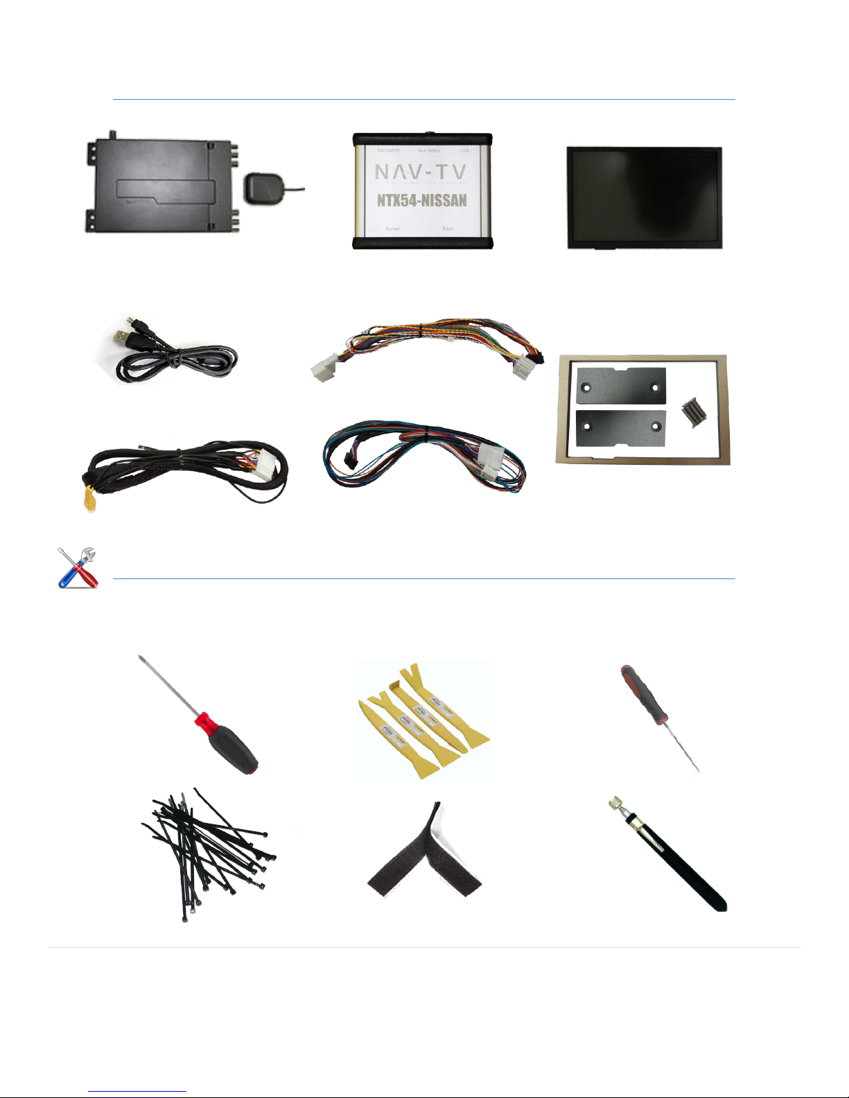
Long Phillips Screwdriver
NTX54-Nissan module
NTV-ASY184
Straight pick
Zip Ties
Velcro
Telescoping Magnet
Plastic panel tool
Garmin Navigation
system and GPS antenna
NTV-NAV009
NTX54 Power T-Harness
NTV-HAR232
OEM Nissan touch
screen monitor
NTV-NAV010
NTX54 Screen T-Harness
NTV-HAR233
Garmin Harness
NTV-HAR225
LCD Trim kit (optional)
NTV-431
USB Cable
NTV-CAB009
Included Parts:
Needed Tools:
Agreement: End user agrees to use this product in compliance with all State and Federal laws. NAV-TV Corp. would not be held liable for misuse of its product.
If you do not agree, please discontinue use immediately and return product to place of purchase. This product is intended for off-road use and passenger
entertainment only.
2 | P a g e

The connector pin outs above are for the black mini Molex connectors that plug into the NTX-NIS/INF
interface module. The view is from the back side of the Molex connectors (the view you would see if
the connectors were plugged into the NTX-NIS/INF module). From left to right is the 18 pin mini Molex
from the 20 pin power plug T-harness, the 22 pin mini Molex from the 24 pin video T-harness and the
24 pin mini Molex from the 24 pin to 24 pin NTX-NIS/INF module to the NTX-54 navigation module.
Module connector layout
NTX54-Nissan Module pin out (wire side)
Video T-Harness (22-pin)
Navigation Harness (24-pin)
*Note: Wire colors may change without warning. Always reference pin locations, not
wire colors!
Video
Navigation
Video T-Harness
Power T-Harness
Power T-Harness (18-pin)
USB
Speaker OUT +
In From Radio +
Speaker OUT In From Radio -
Agreement: End user agrees to use this product in compliance with all State and Federal laws. NAV-TV Corp. would not be held liable for misuse of its product.
If you do not agree, please discontinue use immediately and return product to place of purchase. This product is intended for off-road use and passenger
entertainment only.
3 | P a g e

Overview:
Insert the pick tool or a small screwdriver
into the shift lock hole and depress the shift
lock mechanism
Make sure that the emergency brake is
engaged and then move the shifter into
reverse.
3
2
4
The accessory of the vehicle must be off during the next several steps. Make sure that
either the key is removed from the key cylinder or that the push to start switch is in the off
position. If this step is ignored you will receive an airbag light warning!
Remove the plastic trim ring around the shifter
using a plastic pry tool.
With a pick tool, remove the shift lock hole
cover.
1
The NTX Nissan/Infiniti is a touch screen Navigation interface for compatible 2008 to current Nissan and Infinity
vehicles. The module will also allow the integration of a video source or a front facing camera. During the installation
the original color LCD monitor will be replaced. The installation is performed entirely AT THE RADIO and not at the monitor.
FAILURE TO FOLLOW THESE INSTRUCTIONS MAY LEAD TO PRODUCT FAILURE OR AN AIRBAG MALFUNCTION LIGHT.
G37 Radio & Screen Removal:
Agreement: End user agrees to use this product in compliance with all State and Federal laws. NAV-TV Corp. would not be held liable for misuse of its product.
If you do not agree, please discontinue use immediately and return product to place of purchase. This product is intended for off-road use and passenger
entertainment only.
4 | P a g e

5
Remove the screws from the left and right
bottom corners and pull the HVAC panel
from the bottom up and away from the
dash.
Gently pull the top section back and away from the dash to
release the top clips. Make sure that the vehicle is off and
disconnect all the harnesses from the back of the HVAC panel.
DO NOT turn the key or push the push to start button until
after the HVAC panel has been plugged back in during later
steps.
Remove the screws on the bottom left and
right that holds the monitor trim in place.
These screws were hidden by the HVAC
panel.
Pull the monitor shroud up and back towards the rear of
the vehicle and remove it. The ribbon cable attached to
the shroud should have already been removed in step 6.
7
Remove the two screws holding the top of
the radio bracket and the bottom of the
monitor brackets.
Using a long Phillips screwdriver, remove the two screws holding
the bottom of the radio bracket. You may need the magnet to
retrieve these screws if they drop inside the dash.
9
6
8
10
Agreement: End user agrees to use this product in compliance with all State and Federal laws. NAV-TV Corp. would not be held liable for misuse of its product.
If you do not agree, please discontinue use immediately and return product to place of purchase. This product is intended for off-road use and passenger
entertainment only.
5 | P a g e
 Loading...