

Page 1
NMEA 2000 Network Fundamentals
+
-
A NMEA 2000 network is made of connected NMEA 2000 devices that communicate using basic plug-and-play connectivity.
This guide provides descriptions of the NMEA 2000 connectors and cables sold by Garmin, and the fundamental concepts of installing a
NMEA 2000 network on your boat. If you experience difculty installing a NMEA 2000 network, contact Garmin Product Support or a certied
NMEA 2000 technician. In the USA, contact Garmin Product Support by phone: (913) 397-8200 or (800) 800-1020 or go to
www.garmin.com/support/. In Europe, contact Garmin (Europe) Ltd. at +44 (0) 870.8501241 (outside the UK) or 0808 2380000
(within the UK).
If your boat already contains a NMEA 2000 network and you would like to add Garmin NMEA 2000 components, see page 8.
For a glossary of commonly used NMEA 2000 terms, see page 8.
After you have installed your NMEA 2000 network, use the checklist on page 9 to verify the installation.
Garmin NMEA 2000 Devices and Components:
Garmin uses NMEA 2000 micro connectors on units, sensors, and T-connectors that follow the NMEA 2000 standard and are compatible with
other NMEA 2000 micro connectors, cables, and NMEA 2000-compatible devices. Garmin sensors are commonly packaged with a drop cable,
a T-connector, and two terminators. Garmin displays may also include additional NMEA 2000 components (such as a power cable). The NMEA
2000 components included with a Garmin sensor or display are listed in the product documentation. A diagram on the product box shows which
NMEA 2000 components are included.
Sample Box Diagram (GFS 10)
In the sample box diagram, a complete NMEA 2000 network is shown, and the parts included with the sensor are shaded. In this example, a
T-connector and two terminators are included with a Garmin GFS 10 fuel sensor. A NMEA 2000 power cable, an additional drop/backbone
cable, and additional T-connectors are not included with a GFS 10 fuel sensor. The GFS 10 fuel sensor, as shown by the shaded components on
the box diagram, is intended to be connected to an existing NMEA 2000 network on your boat. If you do not have a NMEA 2000 network on
your boat, this guide will help you assemble one.
January 2008 190-00891-00 Rev. A Printed in Taiwan
Page 2
InstallatIon InstructIons
NMEA 2000 Components
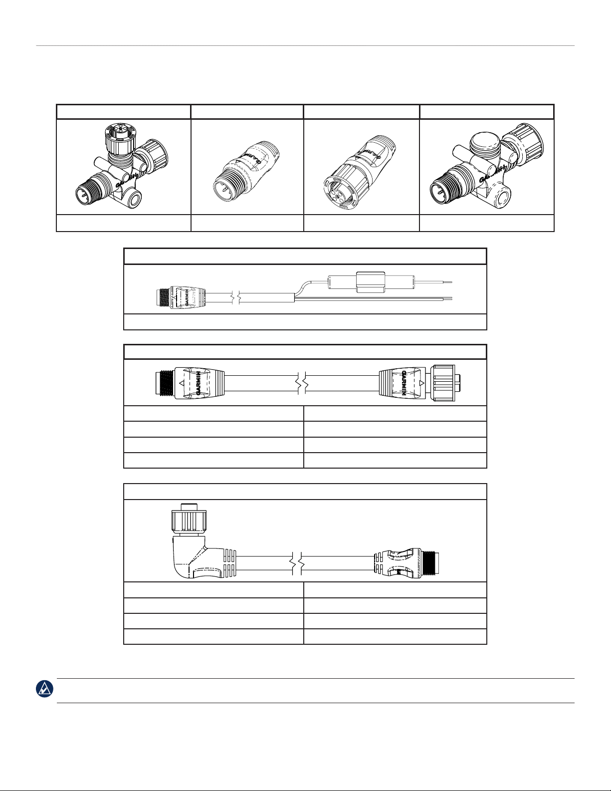
The main components of a NMEA 2000 network are T-connectors, terminators, backbone/drop cables, and a power cable.
T-connector Male Terminator Female Terminator In-line Terminator
010-11078-00 (Garmin part number) 010-11080-00 010-11081-00 010-11096-00
Power Cable
010-11079-00 (2 Meters [6.5 feet]) (3 A fuse included)
Backbone/Drop Cable
305 Millimeters (1 foot) 010-11076-03
2 Meters (6.5 feet) 010-11076-00
6 Meters (20 feet) 010-11076-01
10 Meters (33 feet) (Backbone only) 010-11076-02
Specialty Cable/Connectors
Right Angle Drop Cable, 2 Meters (6.5 feet) 010-11089-00
Field-Installable Connector - Male* 010-11094-00
Field-Installable Connector - Female* 010-11095-00
NMEA 2000 Network Power Switch K00-00368-00
*The eld-installable connectors are used to create custom-length drop cables and custom-length backbone extension cables. The eld-installable connectors can be used to
shorten any Garmin NMEA 2000 drop/backbone cable.
NOTE: All male/female connections are interchangeable. Ensure that the T-connectors are used properly when constructing your NMEA 2000 network.
See page 4.
2 NMEA 2000 Network Fundamentals
Page 3
InstallatIon InstructIons
+
-
Building a NMEA 2000 Network
The main communication channel of a NMEA 2000 network is a backbone to which your NMEA 2000 devices connect. Each NMEA 2000
device connects to the backbone with a T-connector. The NMEA 2000 backbone must be connected to power, and terminators must be installed
at both ends for the network to function correctly.
When you design a NMEA 2000 network, start by creating a diagram of the network. This diagram will include important information such as:
The devices you intend to connect to your network
•
The approximate location of the backbone and devices on your boat
•
Approximate distances between devices and the backbone, as well as the overall length of the backbone
•
Power consumption of each device (Load Equivalency Number)
•
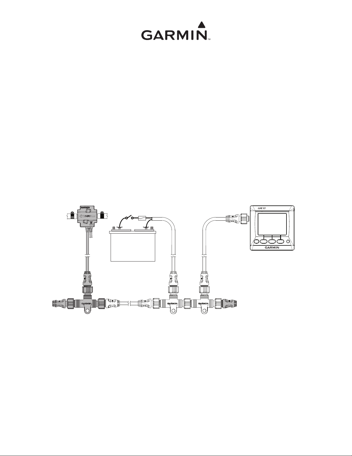
Sample NMEA 2000 Network
Intelligent transducer
Female
terminator
Fuel sensor
Marine instrument
Ignition or
in-line switch
Fuse
Battery - 12 Vdc
Power cable
Backbone extension cable
NMEA 2000 backbone
Chartplotter
Drop cable
T-connector
Male
terminator
NOTE: This diagram illustrates the NMEA 2000 data connections to each device or sensor. Some devices or sensors can be powered by the NMEA
2000 network; others may require a separate power connection. Consult the installation instructions for each device you connect to your NMEA 2000
network to be sure you supply power to the device appropriately.
When building a NMEA 2000 network, you must follow certain rules to make sure your NMEA 2000 network functions correctly. Be sure to
understand the following concepts:
Linear backbone construction (page 4)
•
Power connection and distribution (page 5)
•
Proper termination (page 7)
•
Cable length and device limits (page 8)
•
3NMEA 2000 Network Fundamentals
Page 4
InstallatIon InstructIons
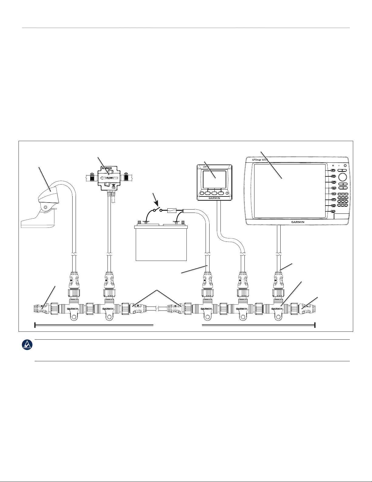
Linear Backbone Construction
Use the NMEA 2000 T-connectors to construct your NMEA 2000 backbone, and extend the backbone with appropriate lengths of backbone
cable if necessary. Use one T-connector per device. Use the sides of the T-connector to construct the backbone of the NMEA 2000 network, and
use the top of the T-connector to attach a NMEA 2000 device. By using only the sides of the T-connectors to construct the backbone, you create
a linear construction to your NMEA 2000 network. T-connectors can be separated by backbone cable or connected directly together
Although the male and female connectors on the T-connectors and backbone cables will t on all sides of a T-connector, it is very important to
use only the top of the T-connector to attach NMEA 2000 devices, not to attach other T-connectors or backbone cables.
To NMEA 2000 devices
and power
T-connector
installed incorrectly
Male
terminator
(also installed
incorrectly)
Female
terminator
Backbone extension cable
CORRECT Linear Backbone Construction
To NMEA 2000 devices
and power
Backbone extension cable
Male
terminator
Female
terminator
INCORRECT Linear Backbone Construction
4 NMEA 2000 Network Fundamentals
Page 5

InstallatIon InstructIons
+
-
Power Connection and Distribution
Your NMEA 2000 network must be connected to a 12 Vdc power supply. Do not connect your NMEA 2000 network to any other voltage
source, such as a 24 Vdc power supply. Use a NMEA 2000 power cable to connect your NMEA 2000 backbone to the auxiliary power switch
on your boat. If you do not have an auxiliary power switch, or if connecting to the auxiliary power switch causes electrical interference, connect
the NMEA 2000 power cable directly to the battery and install an in-line switch.
CAUTION: If you connect the NMEA 2000 network to your battery without an in-line switch, it may drain your battery.
Be sure to ground the NMEA 2000 power cable. Ground the drain wire (bare) to the same location as the ground wire.
The Garmin NMEA 2000 power cable connects to a T-connector like other drop cables. Make sure to connect the NMEA 2000 power cable to
the top of a T-connector; never connect the NMEA 2000 power cable to the side of a T-connector. You can connect power either at the end of
your NMEA 2000 network or in the middle. When planning where to place the power cable and T-connector on your NMEA 2000 network,
you will need to evaluate how the NMEA 2000 devices connected to your network use power. The NMEA 2000 network will work properly as
long as there is no more than a 3 Vdc drop in the supply voltage between the power source and the NMEA 2000 device located farthest from the
power source on the NMEA 2000 network. To determine the voltage drop in your NMEA 2000 network, use this equation:
Voltage Drop = Cable resistance (ohms/m)* × Distance (from the battery to the farthest device, in meters) × Network Load** ×
*Garmin cable resistance value = 0.053
**Network Load = the sum of Load Equivalent Numbers (LEN) between the battery and the end of the network. The LEN for each device should be visible on
the device, or provided in the documentation for the device.
If you calculate a voltage drop of 3.0 Vdc or less, then you can connect power to either the end or the middle of your NMEA 2000 network,
•
0.1
and it will function correctly.
If you calculate a voltage drop of more than 3.0 Vdc, you must connect power to the middle of your NMEA 2000 network. The location will
•
depend on the network load and distance from the battery. Try to balance the voltage drop equally on both sides of the power connection.
If a voltage drop of under 3.0 Vdc is not possible on your NMEA 2000 network, contact a professional installer
•
Examples
The following examples show a correctly designed, end-powered NMEA 2000 network; an incorrectly designed NMEA 2000 network; and a
redesign of the incorrectly designed NMEA 2000 network to correctly balance power on the network.
End-powered NMEA 2000 network, correctly designed:
NMEA 2000compliant device
LEN = 4
Drop cable
Length = 2 m
Power cable
Length = 2 m
Backbone cable
Length = 10 m
NMEA 2000compliant device
LEN = 5
Drop cable
Length = 6 m
NMEA 2000compliant device
LEN = 7
Drop cable
Length = 6 m
Backbone cable
Length = 10 m
When the voltage-drop formula is applied to this example, we see that the voltage drop is less than 3.0 Vdc, so this NMEA 2000 network will
function correctly when powered at the end.
Voltage Drop = 0.053 × (2 + 10 + 10 + 6) × (4 + 5 + 7) × 0.1 = 2.37 Vdc
Cable
Cable
resistance
resistance
Distance Network load
Distance Network load
5NMEA 2000 Network Fundamentals
Page 6

InstallatIon InstructIons
+
-
+
-
End-powered NMEA 2000 network, incorrectly designed:
Power cable
Length = 2 m
NMEA 2000compliant device
LEN = 4
Drop cable
Length = 2 m
Backbone cable
Length = 20 m
NMEA 2000compliant device
LEN = 5
Drop cable
Length = 6 m
Length = 6 m
Backbone cable
Length = 10 m
NMEA 2000compliant device
LEN = 7
Drop cable
When the voltage drop formula is applied to this example, we see that the voltage drop is greater than 3.0 Vdc, so this NMEA 2000 network
will not function correctly when powered at the end.
Voltage Drop = 0.053 × (2 + 20 + 10 + 6) × (4 + 5 + 7) × 0.1 = 3.22 Vdc
Cable
Cable
resistance
resistance
Distance Network load
Distance Network load
This NMEA 2000 network must be redesigned with the power connected to the center of the network in order to function correctly.
Middle-powered NMEA 2000 network, correctly designed:
NMEA 2000compliant device
LEN = 4
NMEA 2000compliant device
LEN = 5
NMEA 2000compliant device
LEN = 7
Drop cable
Length = 2 m
Backbone cable
Length = 20 m
Power cable
Length = 2 m
Drop cable
Length = 6 m
Backbone cable
Length = 10 m
Drop cable
Length = 6 m
When the NMEA 2000 network is redesigned with the power source in the center, you calculate the voltage drop in both directions. If the
T-connector to which you connect the power source is connected directly to another T-connector (as shown in this example), use the LEN from
that device as part of the calculation for both directions.
When the voltage drop formula is applied to both the left and right sides of the power source in this example, we see that the voltage drop is less
than 3.0 Vdc on each side, so the NMEA 2000 network will function correctly.
Voltage Drop Left = 0.053 × (2 + 20 + 2) × (4 + 5) × 0.1 = 1.145 Vdc
Cable
Cable
resistance
resistance
Distance
Distance
Network load
Network load
Voltage Drop Right = 0.053 × (2 + 10 + 6) × (5 + 7) × 0.1 = 1.145 Vdc
NOTE: The equation and examples provide conservative estimates for calculating voltage drop.
6 NMEA 2000 Network Fundamentals
Page 7

InstallatIon InstructIons
Proper Termination
You must install terminators at the ends of your NMEA 2000 backbone for it to function correctly. You have two options when installing
terminators on your NMEA 2000 network.
1. Typical Terminators
If your NMEA 2000 network is built with correct linear backbone construction, you will use one female terminator and one male terminator.
The terminators are installed at opposite ends of your NMEA 2000 network.
To NMEA 2000 devices
and power
Female
terminator
Backbone extension cable
Using Standard Terminators
Male
terminator
2. In-line Terminators
If one or both of the NMEA 2000 devices at opposite ends of your NMEA 2000 network are separated from the rest of the NMEA 2000
network by a length of backbone cable, and the typical T-connector/drop cable/terminator combination is not feasible or is too bulky for the
area, use an in-line terminator instead of the nal T-connector on the backbone. Connect the nal device to the in-line terminator with the
appropriate length of drop cable, or connect the nal device directly to the in-line terminator, without a drop cable.
Standard Termination
To a NMEA
2000 device
Female
terminator
To power
Backbone
extension
cable
Inline Termination
To the nal NMEA 2000 device in the
backbone on this end. Connect the in-line
terminator directly to a NMEA 2000 device,
or use a drop cable up to 6 m (20 ft.) long.
Do not connect additional T-connectors or
terminators.
Inline
terminator
Using an Inline Terminator
CAUTION: Do not use more than two terminators in a NMEA 2000 network.
NOTE: The in-line terminator connects to the NMEA 2000 backbone with a male connector, and to the nal NMEA 2000 device with a female
connector. Because of this, you can only use one in-line terminator on a NMEA 2000 network.
7NMEA 2000 Network Fundamentals
Page 8

InstallatIon InstructIons
Cable Length and Device Limits
When building your NMEA 2000 network, keep in mind these cable length limitations:
The distance between any two points on the NEMA 2000 network must not exceed 100 m (328 ft). To estimate this distance, measure
•
between the terminators on your backbone and add the length of the drop cable for the devices connected to the T-connnectors at the ends of
the Network.
The total length of all drop cables cannot exceed 78 m (256 ft).
•
The maximum length of a single drop cable to a NMEA 2000 device is 6 m (20 ft).
•
No more than 50 NMEA 2000 devices can be connected to your NMEA 2000 network.
•
NMEA 2000 Glossary
T-connector—Three-way connector with 1 male and 2 female micro connectors. A T-connector is used to connect a NMEA 2000 device to the
NMEA 2000 backbone.
Terminator—120 ohm resistor located at each end of the NMEA 2000 backbone. Proper termination helps ensure signal integrity across the
entire length of the backbone.
Inline Terminator
the NMEA 2000 backbone. Simplies installation by not requiring a T-connector, Terminator, and Drop Cable for the device at the end of the
backbone.
Drop Cable
Backbone Cable
A backbone cable extends the NMEA 2000 backbone to connect NMEA 2000 devices located in different places on the boat. The maximum
backbone cable length is 100 m (328 ft).
Device—Electronic hardware that connects to the NMEA 2000 network. A device may only receive data transmitted by other devices on the
network, or may both transmit and receive data on the network.
Network Power—12 Vdc power supplied to the NMEA 2000 network. Power should be connected through a switch (instead of directly
connected to the battery) because some devices are always on when NMEA 2000 power is present. Note: NMEA 2000 devices must operate
from 9–16 Vdc, with a nominal voltage of 12 Vdc.
LEN (Load Equivalency Number)—This number indicates the amount of current a device draws from the NMEA 2000 network.
1 LEN = 50mA. Each device should have an LEN specied on the product or in the product documentation.
—Special terminator with male and female connectors on either end. Allows direct connection to the a device at the end of
—Cable connecting a NMEA 2000 device to the NMEA 2000 backbone. Drop cables are limited to 6 m (20 ft) maximum length.
—In conjunction with T-connectors, the backbone cables create the main communication path of the NMEA 2000 network.
Existing NMEA 2000 Installation Considerations
If your boat has an existing NMEA 2000 installation, and you would like to add Garmin NMEA 2000 equipment, there are a few things to
consider:
Cable Type:
2000 mini connectors and cables in the backbone. Mini connectors are larger than micro connectors, and you will need to use a converter or
adapter to connect with Garmin NMEA 2000 devices.
Garmin uses NMEA 2000 micro connectors for all cables and connectors. Your existing NMEA 2000 network may use NMEA
Power: Is the existing NMEA 2000 network connected to power? A NMEA 2000 network must be connected to power to function correctly
(page 5). Do not connect the NMEA 2000 network to power in more than one location.
Termination: Are terminators installed on the ends of the existing NMEA 2000 backbone? A NMEA 2000 network must be terminated to
function correctly. Do not add more terminators to a NMEA 2000 network if it is already properly terminated.
If you are unsure of any of these considerations, contact your boat manufacturer or a certied NMEA 2000 technician for assistance.
8 NMEA 2000 Network Fundamentals
Page 9

NMEA 2000 Checklist
Use this checklist to conrm your NMEA 2000 installation.
Is the NMEA 2000 network connected to power, and is the power balanced correctly on the network? (page 5)
Is the NMEA 2000 network power connected through the ignition switch - if not, did you install a switch? (page 5)
Is the NMEA 2000 power cable grounded? Is the drain wire (bare) connected to the same ground location? (page 5)
Is the NMEA 2000 network backbone built using linear construction? (page 4)
Are there terminators on both ends of the NMEA 2000 network? (page 7)
Are all drop cables less than 20 ft (6 m)? (page 8)
NMEA 2000 PGN Information
InstallatIon InstructIons
All data transmitted on a NMEA 2000 network are organized into groups. These groups are identied by a parameter group number (PGN) that
describes the type of data contained in the group. All Garmin NMEA 2000 devices use the proprietary PGN numbers 126720 and 61184. All the
other PGN numbers follow the NMEA 2000 standard.
PGN Information on Garmin NMEA 2000 Devices
The following tables list the PGN information for all Garmin NMEA 2000-compliant devices.
GPSMAP 4000/5000 Series Chartplotters
Receive Transmit
059392 ISO Acknowledgment 059392 ISO Acknowledgment
059904 ISO Request 059904 ISO Request
060928 ISO Address Claim 060928 ISO Address Claim
126208 NMEA - Command/Request/Acknowledge Group Function 126208 NMEA - Command/Request/Acknowledge Group Function
126464 Transmit/Receive PGN List Group Function 126464 Transmit/Receive PGN List Group Function
126992 System Time 126996 Product Information
126996 Product Information 127250 Vessel Heading
127250 Vessel Heading 127258 Magnetic Variation
127488 Engine Parameters - Rapid Update 128259 Speed - Water Referenced
127489 Engine Parameters - Dynamic 128267 Water Depth
127505 Fluid Level 129025 Position - Rapid Update
128259 Speed - Water Referenced 129026 COG & SOG - Rapid Update
128267 Water Depth 129029 GNSS Position Data
129025 Position - Rapid Update 129540 GNSS Sats in View
129026 COG & SOG - Rapid Update 129283 Cross Track Error
(Continued)
9NMEA 2000 Network Fundamentals
Page 10

InstallatIon InstructIons
129029 GNSS Position Data 129284 Navigation Data
129539 GNSS DOPs 12985 Navigation - Route/Waypoint Information
129540 GNSS Sats in View 130306 Wind Data
130306 Wind Data 130312 Temperature
130310 Environmental Parameters
130311 Environmental Parameters
130312 Temperature
130313 Humidity
130314 Actual Pressure
GMI 10
Receive Transmit
059392 ISO Acknowledgment 059392 ISO Acknowledgment
059904 ISO Request 059904 ISO Request
060928 ISO Address Claim 060928 ISO Address Claim
126208 NMEA - Command/Request/Acknowledge Group Function 126208 NMEA - Command/Request/Acknowledge Group Function
126464 Transmit/Receive PGN List Group Function 126464 Transmit/Receive PGN List Group Function
126992 System Time 126996 Product Information
126996 Product Information
127250 Vessel Heading
127488 Engine Parameters - Rapid Update
127489 Engine Parameters - Dynamic
127505 Fluid Level
128259 Speed - Water Referenced
128267 Water Depth
129025 Position - Rapid Update
129026 COG & SOG - Rapid Update
129029 GNSS Position Data
129044 Datum
129283 Cross Track Error
129284 Navigation Data
129285 Navigation - Route/WP information
129539 GNSS DOPs
129540 GNSS Sats in View
130306 Wind Data
130310 Environmental Parameters
130311 Environmental Parameters
130312 Temperature
130313 Humidity
130314 Actual Pressure
10 NMEA 2000 Network Fundamentals
Page 11

InstallatIon InstructIons
GPS 17x
Transmit Receive
059392 ISO Acknowledgment 059392 ISO Acknowledgment
060928 ISO Address Claim 059904 ISO Request
126208 NMEA - Command/Request/Acknowledge Group Function 060928 ISO Address Claim
126464 Transmit/Receive PGN List Group Function 126208 NMEA - Command/Request/Acknowledge Group Function
126992 System Time and Date
126996 Product Information
129025 Position - Rapid Update
129026 COG & SOG - Rapid Update
129029 GNSS Position Data
129539 GNSS DOPs
129540 GNSS Sats in View
GFS 10
Transmit Receive
059392 ISO Acknowledgement 059392 ISO Acknowledgement
060928 ISO Address Claim 059904 ISO Request
126208 NMEA–Command/Request/Acknowledge Group Function 060928 ISO Address Claim
126464 Transmit/Receive PGN List Group Function 126208 NMEA–Command/Request/Acknowledge Group Function
126996 Product Information 127489 Engine Parameters - Dynamic
127489 Engine Parameters–Dynamic 127497 Trip Parameters, Engine
127497 Trip Parameters, Engine 127505 Fluid Level (when calibrated on a Garmin chartplotter or
instrument)
127505 Fluid Level (when calibrated on a Garmin chartplotter or
instrument)
Intelliducers
Transmit Receive
059392 ISO Acknowledgement 059392 ISO Acknowledgement
060928 ISO Address Claim 059904 ISO Request
126208 NMEA–Command/Request/Acknowledge Group Function 060928 ISO Address Claim
126464 Transmit/Receive PGN List Group Function 126208 NMEA–Command/Request/Acknowledge Group Function
126996 Product Information
128267 Water Depth
130312 Temperature
11NMEA 2000 Network Fundamentals
Page 12

© Copyright 2008 Garmin Ltd. or its subsidiaries
Garmin International, Inc.
1200 E 151st Street, Olathe, Kansas 66062 USA
Tel. 913/397.8200
Fax. 913/397.8282
Garmin (Europe) Ltd
Liberty House, Hounsdown Business Park, Southampton, Hampshire, SO40 9RB UK.
Tel. 44/0870.8501241 (outside the UK.) or 0808 2380000 (UK only)
Fax. 44/0870.8501251
Garmin Corporation
No. 68, Jangshu 2nd Road, Shijr, Taipei County, Taiwan
Tel. 886/2.2642.9199
Fax. 886/2.2642.9099
Part Number 190-00891-00 Rev. A
 Loading...