

Page 1
®
Do not apply grease or lubricant to the screws when fastening
the remote control to the mounting surface. Grease or other
lubricants can cause damage to the remote control housing.
MS-ERX400 Installation Instructions
Important Safety Information
WARNING
See the Important Safety and Product Information guide in the
product box for product warnings and other important
information.
CAUTION
To avoid possible personal injury, always wear safety goggles,
ear protection, and a dust mask when drilling, cutting, or
sanding.
NOTICE
When drilling or cutting, always check what is on the opposite
side of the surface to avoid damaging the vessel.
What's In the Box
• Mounting gasket
• Mounting template
• Four 8-gauge, self-tapping screws
• Two screw covers
• Dust cover
• Network/power cable
Tools Needed
• Phillips screwdriver
• Electric drill
• Drill bit (size varies based on surface material and screws
used)
• Rotary cutting tool or jigsaw
• Silicone-based marine sealant (optional)
Mounting Considerations
• You must mount the remote control on a flat surface.
• If there is not much clearance behind the mounting surface or
you prefer to drill a smaller hole in the mounting surface, you
can use an MS-ERX400 spacer accessory (010-12922-02)
• If you are connecting the remote control to a stereo that may
be exposed to water, add a drip loop to the cable near the
stereo to allow water to drip off of the cable and avoid
damage to the stereo. The drip loop should include the
Ethernet cable and the power wires.
• If you need to mount the remote control on the exterior of a
boat, you must mount it in a location far above the waterline,
where it is not submerged, and where it cannot be damaged
by docks, pilings, or other pieces of equipment.
• To avoid interference with a magnetic compass, you must
install the remote control at least 15 cm (5.9 in.) away from a
compass.
Mounting the Remote Control
NOTICE
Do not use the remote control as a template when drilling the
mounting holes because this may damage the remote control
and void the warranty.
Before you can mount the remote control, you must select a
location in accordance with the mounting considerations.
Trim the template and adhere it to the mounting surface.
1
Drill a hole inside the corner of the dashed line on the
2
template, and use a jigsaw or rotary cutting tool to cut along
the inside of the solid line on the template.
NOTE: If you are using the accessory spacer and you would
like a smaller hole in the surface, use a 44 mm (13/4) hole
saw to cut the hole shown on the template.
Ensure the mounting holes on the remote control line up
3
with the pilot holes on the template.
Using an appropriately sized drill bit for the mounting surface
4
and screw type, drill the pilot holes.
Remove the template from the mounting surface.
5
Complete an action:
6
• If you are installing the remote control in a dry location,
place the included mounting gasket on the back of the
remote control.
• If you are installing the remote control in a location that is
exposed to water, apply silicone-based marine sealant on
the mounting surface around the cutout.
NOTICE
Do not install the included mounting gasket if you applied
sealant to the mounting surface. Using sealant and the
mounting gasket may reduce water resistance.
If you are using the spacer accessory, install the gasket or
7
sealant on the back of the spacer.
If you will not have access to the back of the remote control
8
after installation, connect the network/power cable to the
back of the remote control, and tighten the locking ring.
If you are using the spacer accessory, install the spacer and
9
gasket or sealant between the mounting surface and the
remote control.
Refer to the diagram that came with the spacer.
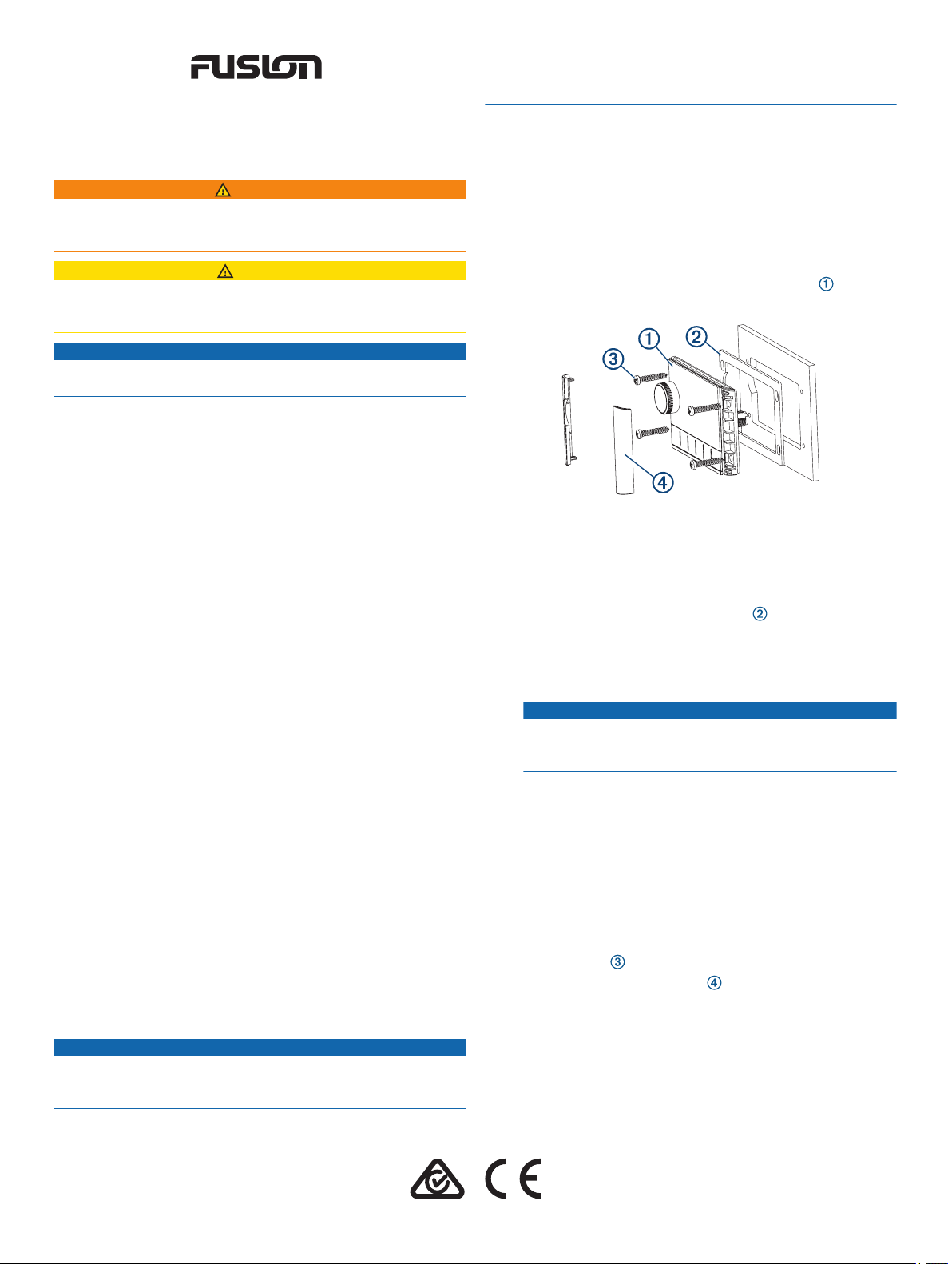
Secure the remote control to the mounting surface using the
10
included screws .
Snap the screw covers in place .
11
Power and Network Considerations
If you must extend the power and ground wires, you must use
the appropriate gauge of wires. 18 AWG (0.82 mm2) wires are
suitable for most installations.
If you must extend the network cable, extension cables and
couplers are available. See your Garmin® dealer for details.
GUID-0E8EFC1A-5B75-4554-B74B-B79F5E3CC812 v2January 2021
Page 2
This remote control can either connect to a single stereo, such
as an MS-RA770, or it can connect to the Fusion PartyBus
™
network to view and control all of the stereos on the network.
You can use this example to help plan a basic Fusion PartyBus
network. If you need information about creating a more
advanced network with additional stereos and devices, see the
installation instructions for your compatible stereo.
MS-ERX400 remote control
Wired network switch or wired network router
Compatible stereo, such as an MS-RA770
Compatible stereo, such as an MS-RA670
Connecting to Power and the Network
Route the network/power cable to the stereo or to the
1
network switch or router.
NOTICE
Do not connect the cable to the stereo until after you have
connected the power wires to avoid possible damage to the
stereo.
More Information
Software Updates
You must update the software for this device using a connected
compatible stereo or using the Fusion-Link™ app. To make sure
the device functions correctly with all compatible stereos on the
Fusion PartyBus network, you should update the software in all
FUSION devices after you install this device.
For software update instructions, see the online owner's manual
for this device or for a connected compatible stereo.
Specifications
Dimensions (W × H) 11 × 7 cm (4.32 × 2.76 in.)
Dust cover dimensions (W × H) 11.8 × 8 cm (4.66 × 3.15 in.)
Weight (excluding cable) 100 g (3.5 oz.)
Input voltage From 10.8 to 32 Vdc negative ground
Current (normal operation at
12 Vdc)
Current (normal operation at
14.4 Vdc)
Current (device off) Less than 50 mA
Fuse 1 A ATO blade-type
Compass-safe distance 15 cm (6.1 in.)
Operating temperature From 0 to 50°C (from 32 to 122°F)
Storage temperature From -20 to 70°C (from -4 to 158°F)
Water rating IEC 60529 IPX6 and IPX7
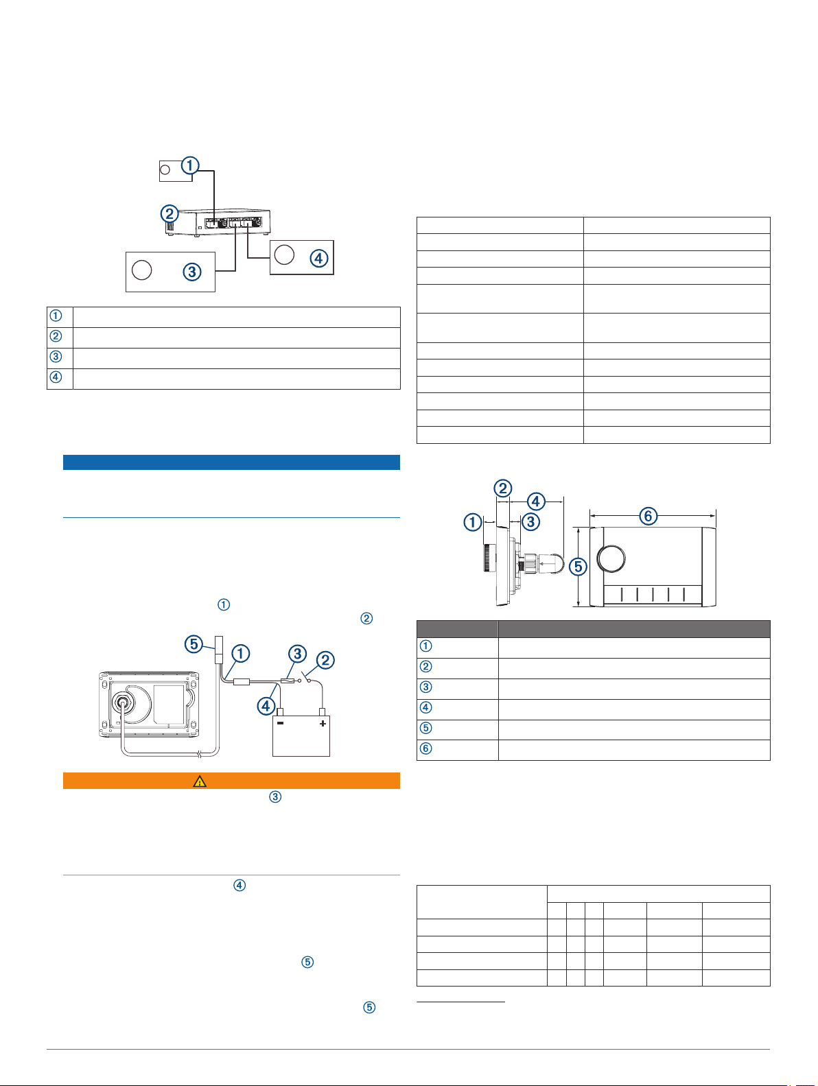
Dimensions
150 mA
125 mA
1
TIP: To avoid running additional wires to the battery, you can
connect the power and ground wires from this remote control
to the power and ground wires used by the stereo. The
stereo should be connected to power though the ignition or
another manual switch.
Connect the red power wire to the positive (+) battery
2
terminal through the ignition or another manual switch .
WARNING
Do not remove the in-line fuse holder , to prevent the
possibility of injury or product damage caused by fire or
overheating. Connecting the wire without the appropriate fuse
in place voids the product warranty. If you must extend the
wire run, you should relocate the fuse so it is near the power
source.
Connect the black ground wire to the negative (-) battery
3
terminal.
Select an option:
4
• If you are using this device to control one stereo and do
not have additional devices on a Fusion PartyBus
network, connect the network connector to the
ETHERNET port on the stereo.
• If you have a network on the boat connecting multiple
compatible devices, connect the network connector to
an open port on the network switch or router.
Item Measurement
12.3 mm (0.48 in.)
10 mm (0.39 in.)
10.9 mm (0.43 in.)
49.1 mm (1.93 in.)
70 mm (2.76 in.)
110 mm (4.32 in.)
連絡地址
製造銷售:台灣國際航電股份有限公司
聯絡地址:新北市汐止區樟樹二路 68 號
電 話:(02)2642-8999
客服專線:(02)2642-9199
物質宣言
部件名称 有毒有害物质或元素
铅 汞 镉 六价铬 多溴联苯 多溴二苯醚
印刷电路板组件 X O O O O O
屏幕/背光 X O O O O O
金属零件 X O O O O O
电缆 电缆组件 连接器 X O O O O O
1
The device withstands incidental exposure to water of up to 1 m for up to 30 min,
and is protected against powerful jets of water. For more information, go to
www.garmin.com/waterrating.
2 MS-ERX400 Installation Instructions
Page 3

本表格依据 SJ/T11364 的规定编制。
O: 代表此种部件的所有均质材料中所含的该种有害物质均低于
(GB/T26572) 规定的限量
X: 代表此种部件所用的均质材料中, 至少有一类材料其所含的有害
物质高于
(GB/T26572) 规定的限量
*該產品說明書應提供在環保使用期限和特殊標記的部分詳細講解
產品的擔保使用條件。
© 2020 Garmin Ltd. or its subsidiaries
Garmin®, the Garmin logo, Fusion®, and the Fusion logo, are trademarks of Garmin Ltd.
or its subsidiaries, registered in the USA and other countries. These trademarks may not
be used without the express permission of Garmin.
M/N: A03775
產
品
MS-ERX400 Installation Instructions 3
Page 4

© 2020 Garmin Ltd. or its subsidiaries www.fusionentertainment.com
 Loading...