

Garmin Montana 700, Montana 700i, Montana 750i User manual [de]

Marine Mount Instructions..................................................................................................................2
Instructions pour le support de fixation pour bateau.......................................................................... 4
Istruzioni per l'installazione su staffa nautica..................................................................................... 7
Bootshalterung – Anweisungen....................................................................................................... 10
Instrucciones del soporte para navegación..................................................................................... 13
Instruções para suporte marítimo.................................................................................................... 16
Instrukcje montażu uchwytu do urządzeń morskich........................................................................ 19
Pokyny k námořnímu držáku........................................................................................................... 22
Navodila za pomorski nosilec.......................................................................................................... 24
Upute za montiranje nautičkog nosača............................................................................................ 26
Инструкции по установке судового крепления............................................................................ 28
Garmin® and the Garmin logo are trademarks of Garmin Ltd. or its subsidiaries, registered in the USA and other countries. These trademarks may not be used without the express permission of Garmin.
El número de registro COFETEL/IFETEL puede ser revisado en el manual a través de la siguiente página de internet.
GUID-EFE10BC9-4C8E-4C48-9A7E-55BD727DDE56 v2May 2020
Marine Mount Instructions
WARNING
See the Important Safety and Product Information guide in the
GPS device product box for product warnings and other
important information.
Garmin® strongly recommends having an experienced installer
with the proper knowledge of electrical systems install the
device. Incorrectly wiring the power cable can result in damage
to the vehicle or the battery and can cause bodily injury.
CAUTION
Always wear safety goggles, ear protection, and a dust mask
when drilling, cutting, or sanding.
NOTICE
The metal contacts on the GPS device and the mount should be
kept dry to avoid equipment damage. Use the weather cap on
the mount at all times when the unit is not mounted to keep the
metal contacts dry and protected.
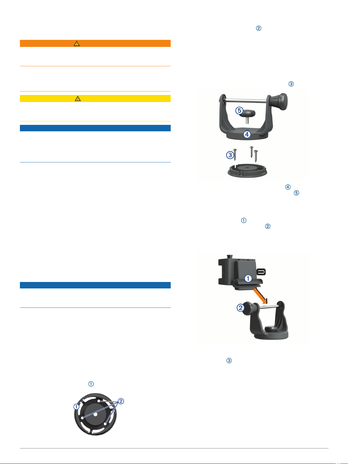
• If you intend to secure the base with self-tapping screws,
drill three 1.5 mm (1/16 in.) starter holes.
NOTE: Do not make the holes deeper than half of the
screw length.
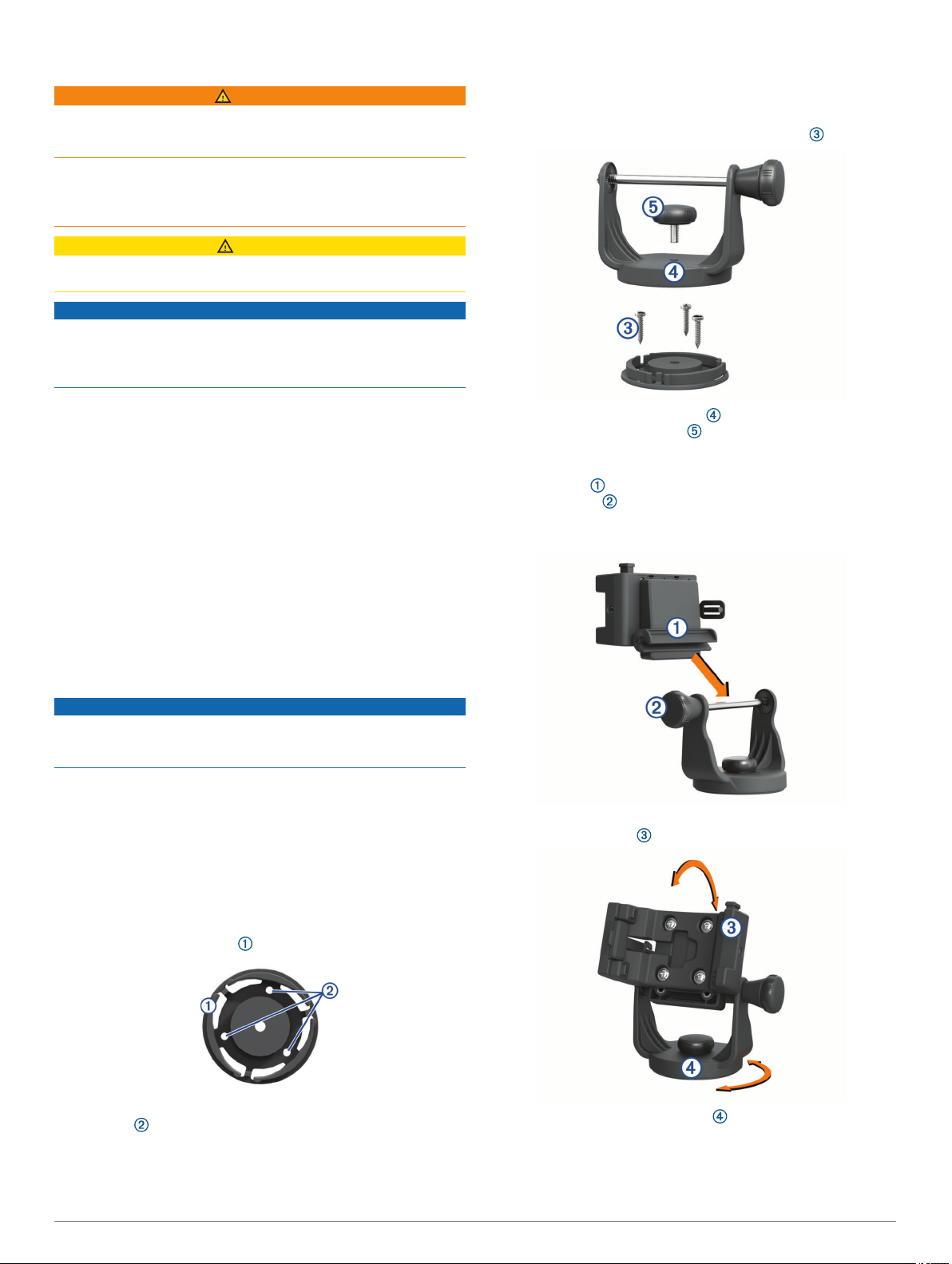
Secure the swivel base with the bolts or screws .
4
To obtain the best performance and to avoid damage to your
boat, install the device according to these instructions.
Read all installation instructions before proceeding with the
installation. If you experience difficulty during the installation,
contact Garmin Product Support.
Tools Needed
• Drill
• Phillips screwdriver
• 3 bolts or 3 screws:
◦ #8 (4 mm) pan-head machine bolts with nuts and washers
and a 5 mm (5/32 in.) drill bit
◦ #8 (4 mm) pan-head self-tapping screws and a 1.5 mm
(1/16 in.) drill bit
Mounting Considerations
NOTICE
The swivel base must be mounted using pan-head machine
bolts or self-tapping screws. Using screws with countersunk
heads can damage the mounting bracket.
The device should be mounted in a location that provides a clear
view of the screen and is easy to reach.
The device should be mounted in a location that is sturdy
enough to support the mount and device.
The device must be mounted in a location that allows room to
route and connect the cables. You should allow at least 8 cm
(3 in.) of clearance behind the case.
Place the swivel mount bracket over the swivel base and
5
secure it with the short knob .
Installing the Mount on the Mounting Bracket
Align the slot on the back of the cradle with the long
1
mounting knob , and slide the cradle into place on the bar.
NOTE: You can turn the long mounting knob to adjust the
width of the bracket arms.
Adjust the angle of the cradle, and tighten the long mounting
2
knob until the cradle is secure.
Mounting the Bracket Assembly
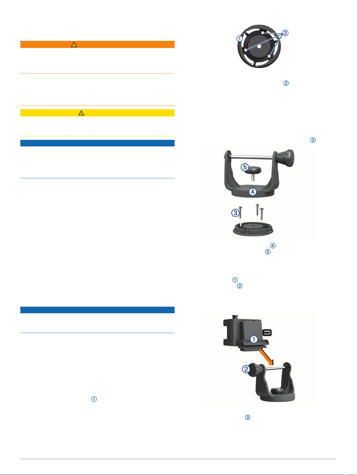
Separate the swivel base from the mount.
1
Using the swivel base as a template, mark the pilot hole
2
locations .
Select an option:
3
• If you intend to secure the base with machine bolts, drill
three 5 mm (5/32 in.) holes.
2 Installation Instructions
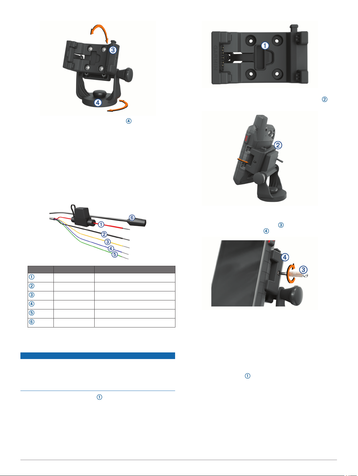
Rotate the swivel mount bracket to an optimal viewing
3
angle, and tighten the knob.
The bracket clicks as you turn it.
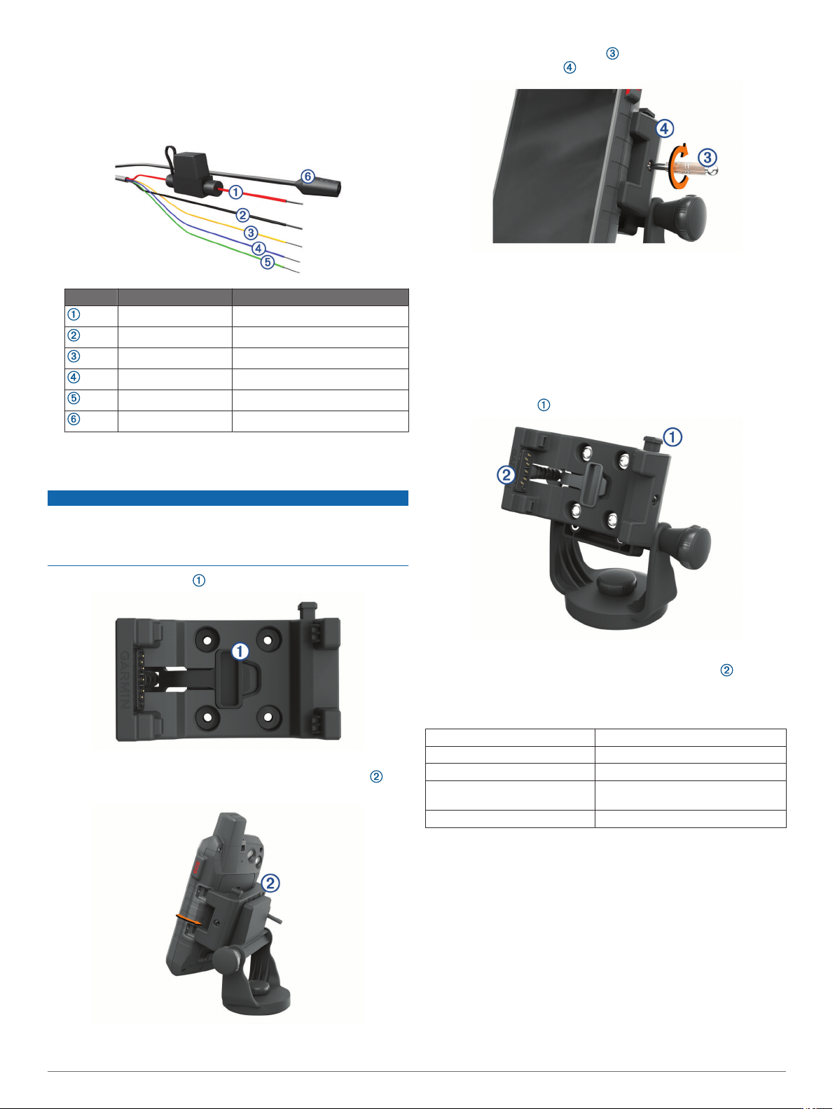
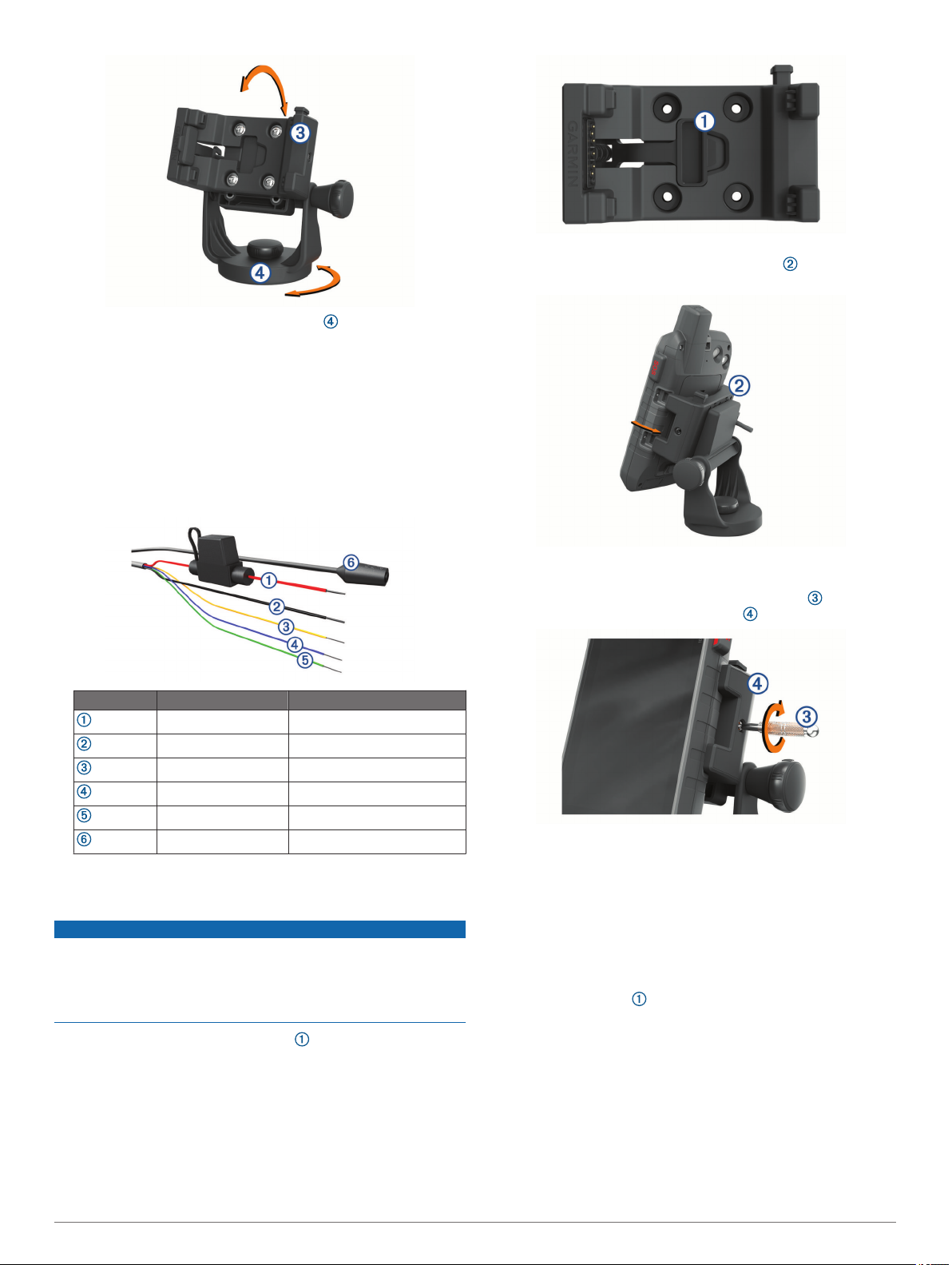
Connecting Power to the Mount
Select a mounting location based on available power
1
sources, safe cable routing, and an unobstructed view.
You should not run cables near high-heat sources.
Connect the cables.
2
Item Wire Color Wire Function
Red (+) Power
Black (-) Ground
Yellow Serial data input
Blue Serial data output
Green Serial ground wire
Audio jack
Insulate and secure unconnected wires.
3
Using the security screw tool , tighten the security screw on
4
the side of the mount .
NOTE: The security screw is used to deter device theft and
helps prevent you from accidentally pressing the release
latch.
Removing the Device from the Mount
When you do not plan to use the device for an extended period
of time, you should remove the device from the mount or power
it from an ignition-controlled relay.
Loosen the security screw.
1
Press the button on the mount to release the device.
2
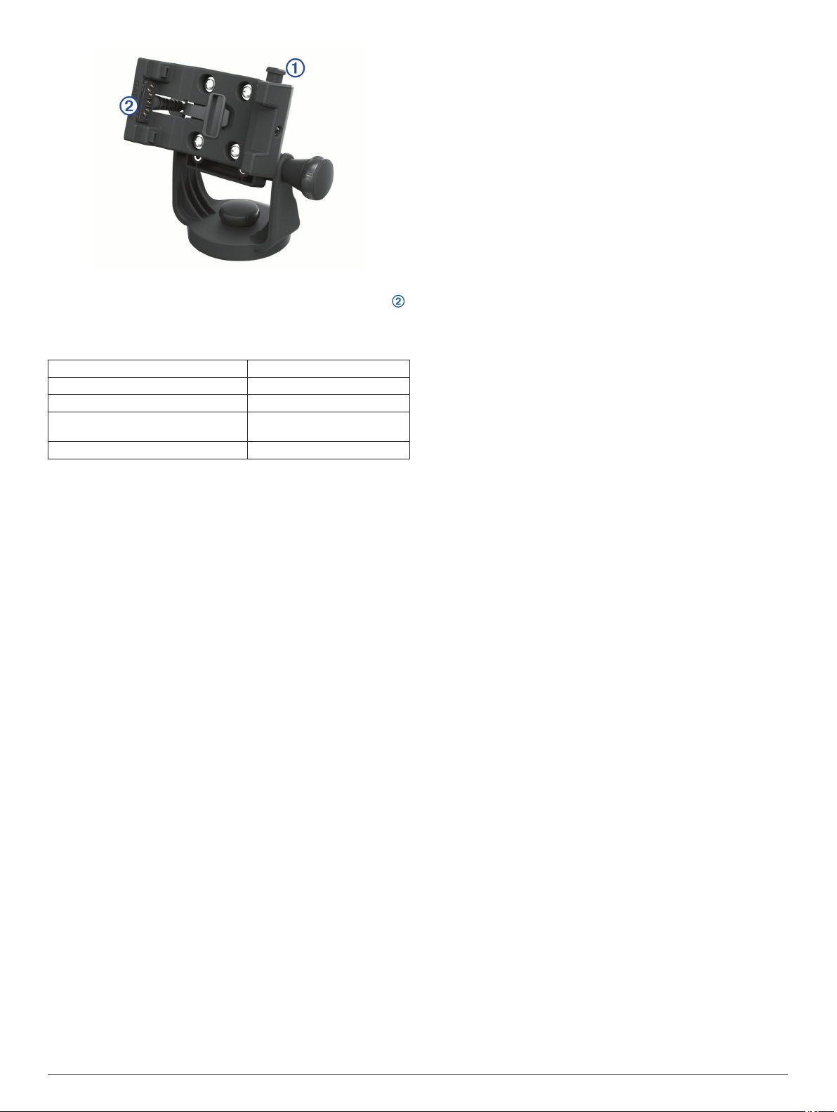
Installing the Device in the Mount
NOTICE
Before you place the device in the mount, ensure the metal
contacts on the device and the mount are dry. Moisture on the
contacts causes equipment damage. Use the weather cap to
keep the mount cradle dry.
Place the weather cap in the storage area on the mount.
1
Align the contacts on the device with the contacts in the
2
mount, and place the side of the device into the cradle ,
contacts first.
Lift the device out of the mount.
3
Place the weather cap securely over the contacts on the
4
cradle.
Specifications
Fuse 3 A
Input voltage 10 to 30 V
Input current 1.5 A Max.
Input current without device
installed
Operating temperature range From -20º to 60ºC (from -4º to 140ºF)
0.5 mA Max.
Limited Warranty
The Garmin standard limited warranty applies to this accessory.
For more information, go to www.garmin.com/support/warranty.
Tilt the device to the opposite side until it snaps into place to
3
prevent the device from falling out.
Installation Instructions 3
Instructions pour le support de
fixation pour bateau
AVERTISSEMENT
Consultez le guide Informations importantes sur le produit et la
sécurité inclus dans l'emballage du GPS pour prendre
connaissance des avertissements et autres informations sur le
produit.
Garmin vous conseille vivement de faire installer l'appareil par
un technicien expérimenté disposant des connaissances
appropriées en matière de circuits électriques. Le raccordement
incorrect du câble d'alimentation peut endommager le véhicule
ou la batterie et entraîner des blessures corporelles.
ATTENTION
Portez toujours des lunettes de protection, un équipement
antibruit et un masque anti-poussière lorsque vous percez,
coupez ou poncez.
AVIS
Les contacts métalliques de l'appareil GPS et du support doivent
être conservés à l'abri de l'humidité, afin d'éviter d'endommager
le matériel. Utilisez toujours le capuchon étanche du support
lorsque l'appareil n'est pas installé afin de protéger les contacts
métalliques de l'humidité.
Pour obtenir des performances optimales et éviter toute
détérioration du bateau, installez l'appareil selon les instructions
suivantes.
Lisez toutes les instructions d'installation avant de procéder à
l'installation. Si vous rencontrez des difficultés durant
l'installation, contactez le service d'assistance produit de
Garmin.
En utilisant la base pivotante comme modèle, marquez
2
l'emplacement des trous d'implantation .
Sélectionnez une option :
3
• Si vous voulez fixer la base à l'aide de boulons
mécaniques, percez trois trous de 5 mm (5/32 po).
• Si vous voulez fixer la base à l'aide de vis autoperceuses,
percez trois trous d'implantation de 1,5 mm (1/16 po).
REMARQUE : la profondeur des trous ne doit pas
dépasser la moitié de la longueur de la vis.
Fixez la base pivotante à l'aide des boulons ou vis .
4
Outils requis
• Perceuse
• Tournevis cruciforme
• 3 écrous ou 3 vis :
◦ Boulons mécaniques à tête cylindrique n° 8 (4 mm) avec
écrous et rondelles et un foret de 5 mm (5/32 po)
◦ Vis autoperceuses à tête cylindrique n° 8 (4 mm) et un
foret de 1,5 mm (1/16 po)
Considérations relatives au montage
AVIS
La base pivotante doit être fixée à l'aide de boulons mécaniques
ou de vis autoperceuses. Si vous utilisez des vis à tête fraisée,
vous risquez d'endommager le support de montage.
L'appareil doit être installé dans un endroit offrant une vue
dégagée de l'écran et qui soit facile à atteindre.
L'appareil doit être installé dans un endroit suffisamment solide
pour supporter le poids du support et de l'appareil.
L'appareil doit être installé dans un endroit offrant assez
d'espace pour acheminer et connecter les câbles. Vous devez
laisser au moins 8 cm (3 po) d'espace libre derrière le boîtier.
Montage du support
Séparez la base pivotante du support.
1
Placez le support d'étrier pivotant sur la base pivotante et
5
fixez-le à l'aide du bouton court .
Installation du support sur le support de fixation
Alignez l'encoche située à l'arrière du socle avec le long
1
bouton de montage , puis faites glisser le socle pour le
placer sur la barre.
REMARQUE : vous pouvez faire pivoter le long bouton de
montage pour régler la largeur des bras du support.
Réglez l'angle du socle et serrez le long bouton de montage
2
jusqu'à ce que le socle soit correctement fixé.
4 Instructions d'installation
Faites tourner le support d'étrier pivotant pour qu'il offre un
3
angle de vue optimal, puis serrez la vis.
Le support émet un déclic lorsque vous le faites pivoter.
Raccordement du support à l'alimentation
Choisissez un emplacement de montage en vous assurant
1
de disposer d'une source d'alimentation à proximité, de
pouvoir acheminer les câbles de manière sécurisée et de
disposer d'une vue dégagée.
Il est déconseillé d'acheminer des câbles près de sources de
chaleur élevée.
Connectez les câbles.
2
Alignez les contacts métalliques de l'appareil avec ceux du
2
support, puis insérez le côté de l'appareil dans le socle , en
commençant par les contacts.
Inclinez l'appareil vers le côté opposé jusqu'à ce qu'il se
3
mette en place, afin d'éviter qu'il ne tombe.
À l'aide de l'outil pour vis de sécurité , serrez la vis de
4
sécurité sur le côté du support .
Élément Couleur du fil Fonction du fil
Rouge (+) Alimentation
Noir (-) Terre
Jaune Entrée des données série
Bleu Sortie des données série
Vert Fil de terre des données série
Prise jack audio
Isolez et sécurisez les fils non connectés.
3
Installation de l'appareil sur le support
AVIS
Avant d'installer l'appareil dans le support, assurez-vous que le
support et les contacts métalliques de l'appareil sont secs. Vous
risquez d'endommager votre équipement si les contacts sont
mouillés. Utilisez le capuchon étanche pour protéger le socle
des intempéries.
Placez le capuchon étanche dans l'emplacement du
1
support prévu à cet effet.
REMARQUE : la vis de sécurité sert à éviter le vol de
l'appareil et un appui accidentel sur la languette de
déverrouillage.
Retrait de l'appareil du support
Si vous prévoyez de ne pas utiliser l'appareil pendant une
période prolongée, il est conseillé de le retirer du support ou de
l'alimenter via un relais contrôlé par l'allumage du véhicule.
Desserrez la vis de sécurité.
1
Appuyez sur le bouton situé sur le support pour libérer
2
l'appareil.
Instructions d'installation 5

Soulevez l'appareil du support.
3
Placez le capuchon étanche sur les contacts du socle.
4
Caractéristiques
Fusible 3 A
Alimentation De 10 à 30 V
Courant en entrée 1,5 A maximum
Courant en entrée sans l'appareil 0,5 mA maximum
Plage de températures de fonctionne-
ment
De -20 à 60 ºC (de -4 à 140 ºF)
Garantie limitée
La garantie limitée standard de Garmin s'applique à cet
accessoire. Pour plus d'informations, rendez-vous sur le site
www.garmin.com/support/warranty.
6 Instructions d'installation
Istruzioni per l'installazione su staffa
nautica
AVVERTENZA
Per avvisi sul prodotto e altre informazioni importanti, consultare
la guida Informazioni importanti sulla sicurezza e sul prodotto
inclusa nella confezione del dispositivo GPS.
Garmin consiglia di far installare il dispositivo esclusivamente da
tecnici esperti e qualificati. Il collegamento errato del cavo di
alimentazione potrebbe provocare danni al prodotto o alla
batteria, nonché lesioni alla persona.
ATTENZIONE
Durante le operazioni di foratura, taglio o carteggiatura,
indossare degli occhiali protettivi, una maschera antipolvere e
un'adeguata protezione per l'udito.
AVVISO
I contatti metallici sul dispositivo GPS e sulla staffa devono
essere mantenuti asciutti per evitare di danneggiare
l'apparecchiatura. Utilizzare un cappuccio protettivo sulla staffa
ogni volta che l'unità non è installata per mantenere i contatti
metallici asciutti e protetti.
Per ottenere le massime prestazioni ed evitare danni
all'imbarcazione, installare il dispositivo attenendosi alle
istruzioni riportate di seguito.
Prima di procedere all'installazione, leggere attentamente le
istruzioni. In caso di difficoltà durante l'installazione, contattare il
servizio di assistenza ai prodotti di Garmin.
Strumenti necessari per l'installazione
• Trapano
• Cacciavite a croce
• 3 bulloni o 3 viti:
◦ Bulloni a testa piatta n.8 (4 mm) con dadi e rondelle e una
punta da trapano da 5 mm (5/32 poll.)
◦ Viti autofilettanti a testa piatta numero 8 (4 mm) e una
punta da trapano da 1,5 mm (1/16 poll.)
Utilizzando la base girevole come modello, contrassegnare le
2
posizioni dei fori di riferimento .
Selezionare un'opzione:
3
• Se si desidera fissare la base mediante bulloni, praticare
tre fori da 5 mm (5/32 poll.).
• Se si desidera fissare la base mediante viti autofilettanti,
praticare tre fori guida da 1,5 mm (1/16 poll.).
NOTA: la profondità dei fori non deve essere superiore a
metà della lunghezza della vite.
Fissare la base girevole con tre bulloni o viti .
4
Posizionare la staffa di montaggio girevole sulla base
5
girevole e fissarla mediante la manopola corta .
Installazione del supporto sulla staffa di montaggio
Allineare la scanalatura sul retro della base di appoggio
1
alla manopola di montaggio lunga , quindi far scorrere la
base di appoggio in posizione sulla barra.
NOTA: è possibile ruotare la manopola di montaggio lunga
per regolare la larghezza dei bracci della staffa.
Informazioni sull'installazione
AVVISO
La base girevole deve essere installata utilizzando bulloni a
testa piatta o viti autofilettanti. Se si utilizzano viti a testa
svasata, si rischia di danneggiare la staffa di installazione.
Il dispositivo deve essere installato in una posizione che
garantisce una visualizzazione nitida dello schermo e semplice
da raggiungere.
Il dispositivo deve essere installato in una posizione abbastanza
robusta da sostenere il supporto e il dispositivo.
Il dispositivo deve essere installato in una posizione che lascia
libero abbastanza spazio per posizionare e collegare i cavi.
Occorre lasciare uno spazio di almeno 8 cm (3 poll.) dietro
l'unità.
Montaggio del gruppo staffa
Separare la base girevole dal supporto.
1
Regolare l'angolazione della base di appoggio e stringere la
2
manopola di montaggio lunga fino a fissare saldamente la
base di appoggio .
Istruzioni di installazione 7
Ruotare la staffa di montaggio girevole fino a raggiungere
3
un angolo di visualizzazione ottimale e stringere la manopola.
Quando viene ruotata, la staffa scatta.
Collegamento dell'alimentazione al supporto
Scegliere una posizione di installazione vicino alle fonti di
1
alimentazione disponibili, dove sia possibile posizionare al
sicuro i cavi e dove sia garantita una visualizzazione priva di
ostacoli.
Non passare i cavi in prossimità di fonti di calore.
Collegare i cavi.
2
Elemento Colore del cavo Funzione cavo
Rosso (+) Accensione
Nero (-) Terra
Giallo Ingresso dei dati seriali
Blu Uscita dei dati seriali
Verde Cavo di terra seriale
Jack audio
Isolare e fissare i cavi non collegati.
3
Allineare i contatti sul dispositivo ai contatti nel supporto e
2
posizionare il lato del dispositivo nella base , inserendo
prima i contatti.
Inclinare il dispositivo sul lato apposito finché non scatta in
3
posizione per impedire che cada.
Utilizzando lo strumento per la vite di sicurezza , serrare la
4
vite di sicurezza sul lato del supporto .
NOTA: la vite di sicurezza viene utilizzata per impedire il furto
del dispositivo ed evitare la pressione accidentale del fermo
di rilascio.
Installazione del dispositivo nel supporto
AVVISO
Prima di posizionare il dispositivo nel supporto, accertarsi che i
contatti metallici sul dispositivo e sul supporto siano asciutti. I
contatti bagnati possono danneggiare l'apparecchiatura.
Utilizzare il cappuccio protettivo per mantenere asciutta la base
di appoggio del supporto.
Posizionare il cappuccio protettivo nell'area di appoggio
1
del supporto.
8 Istruzioni di installazione
Rimozione del dispositivo dal supporto
Prima di riporre il dispositivo per un lungo periodo di tempo, è
necessario rimuovere il dispositivo dal supporto o accenderlo da
un relè controllato dal motore.
Allentare la vite di sicurezza.
1
Premere il pulsante sul supporto per rimuovere il
2
dispositivo.
Estrarre il dispositivo dal supporto sollevandolo.
3
Posizionare saldamente il cappuccio protettivo sui contatti
4
della base.
Caratteristiche tecniche
Fusibile 3 A
Tensione operativa Da 10 a 30 V
Corrente in entrata 1,5 A Max.
Corrente in entrata senza dispositivo
installato
Intervallo temperatura di esercizio Da -20 a 60 °C (da -4 a 140 °F)
0,5 mA Max.
Garanzia limitata
Il presente accessorio è coperto dalla garanzia limitata standard
di Garmin. Per ulteriori informazioni, visitare il sito Web
www.garmin.com/support/warranty.
Istruzioni di installazione 9
 Loading...