

Garmin GPSMAP740s/GMR18HD Bundle, GPSMAP 750s, GPSMAP 750 Installation Instructions
GPSMAP® 700 Series Installation Instructions
WARNING
See the Important Safety and Product Information guide in the product box for product warnings and other important information.
CAUTION
Always wear safety goggles, ear protection, and a dust mask when drilling, cutting, or sanding.
Notice
When drilling or cutting, always check what is on the opposite side of the surface to avoid damaging your boat.
The GPSMAP 700 series chartplotter must be properly installed according to the following instructions. You need the appropriate fasteners,
tools, and mounts listed in each section. These items are available at most marine dealers.
Contact Garmin® Product Support if you have any questions while installing your GPSMAP 700 series chartplotter. In the USA, go to www.
garmin.com/support, or contact Garmin USA by phone at (913) 397.8200 or (800) 800.1020. In the UK, contact Garmin (Europe) Ltd. by phone
at 0808 2380000. In Europe, go to www.garmin.com/support and click Contact Support for in-country support information, or contact Garmin
(Europe) Ltd. by phone at +44 (0) 870.8501241.
Before installing your GPSMAP 700 series chartplotter, conrm that the package contains the items listed on the box. If any parts are missing,
contact your Garmin dealer immediately.
Product Registration
Help us better support you by completing our online registration today. Go to http://my.garmin.com. Keep the original sales receipt, or a
photocopy, in a safe place.
For future reference, write the serial number assigned to your GPSMAP 700 series chartplotter in the space provided. The serial number is
located on a sticker on the back of the device.
Chartplotter serial number:
To install the GPSMAP 700 series chartplotter, you must:
1. Mount the GPSMAP 700 series chartplotter.
2. Connect the chartplotter to power (page 5).
3. Ensure that the chartplotter software is up-to-date (page 7).
The following additional installation options are not necessary in order to use the GPSMAP 700 series chartplotter. They have
been included for your convenience:
• Connecting the chartplotter to a NMEA 2000 network (page 6)
• Connecting the chartplotter to a GA 30 remote GPS antenna (page 6).
• Connecting the chartplotter to a Garmin marine radar (page 6).
• Connecting the chartplotter to other NMEA 0183-compatible devices such as a VHF radio with DSC (page 5).
• Connecting the chartplotter to a sonar transducer (“s” models only) (page 6).
Mounting the Chartplotter
You can mount the GPSMAP 700 series chartplotters using one of two methods. You can use the included bracket and hardware to bail mount
the chartplotter, or you can use the included template and hardware to ush mount the chartplotter.
Mount the GPSMAP 700 series chartplotter in a location that provides a clear, glare-free view of the display and easy operation of the power
key and the touch screen.
February 2010 Part Number 190-01155-02 Rev. B Printed in Taiwan
Bail Mounting the Chartplotter
Use the included bracket to bail mount the GPSMAP 700 series chartplotter. You can route cables from under the mounting surface through the
included bail-mount bracket, though it is not necessary. See page 3 for instructions on installing the bail-mount bracket without routing cables
through the bracket.
Hardware (included):
• Bail-mount bracket
• Cable-organization bracket
• Bail-mount template
• Four 35 mm M 4.2 × 1.4 screws (to secure the bail-mount bracket )
• Two 20 mm M 3.5 × 1.3 screws (to secure the cable-organization
bracket)
To install the bail-mount bracket with the cables routed through the bracket:
1. Using the included bail-mount bracket template, determine the best place to install the bracket. Be sure to leave adequate clearance behind
the chartplotter for the wiring.
NOTE: To avoid interference, mount the GPSMAP 700 series chartplotter at least 32 in. (813 mm) from a magnetic compass.
2. The bail-mount bracket template has adhesive on the back. Remove the
protective liner and apply the template to the location at which you want to install
the bail-mount bracket.
3. Use a 1 1/4 in. (32 mm) drill bit to drill the pass-through hole in the center of the
template.
4. Use a use a 1/8 in. (3 mm) drill bit to drill the six pilot holes marked on the bailmount template.
NOTE: If you are mounting the chartplotter in berglass, it is recommended to use
a countersink bit to drill a clearance-counter bore through only the top gel-coat
layer. This will help to avoid any cracking in the gel-coat layer when the screws
are tightened.
5. Remove the bail-mount bracket template from the mounting surface.
6. Route the cables pertinent to your installation through the hole you drilled in step 3,
from under the mounting surface.
If you plan to use all four cables, route them in the following order to ensure that
they will all t correctly:
Radar cable
•
Power/data wiring cable
•
GA 30 GPS antenna cable
•
NMEA 2000 cable
•
NOTE: Do not install the locking ring (page 4) on the power/data or radar cable until after you route it through the mounting surface.
7. Place the cable-organization bracket around the cables and into the 1 1/4 in. (32 mm) hole you drilled in step 3.
8. Use the two included 20 mm M 3.5 × 1.3 screws to secure the cable-organization bracket to the mounting surface.
NOTE: Stainless-steel screws may bind when screwed into berglass and
overtightened. Garmin recommends applying an anti-galling, stainless anti-seize
lubricant to the screw before using.
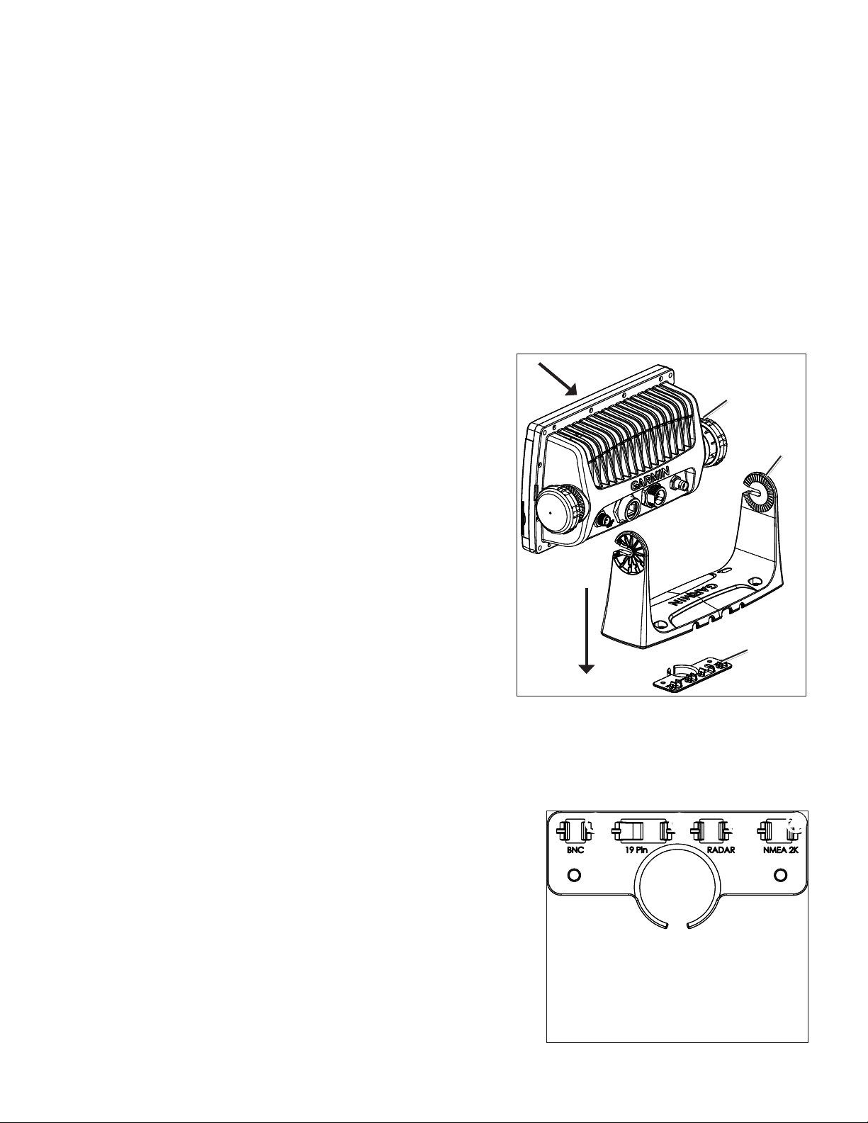
9. Extend 6–7 in. (152–178 mm) of cable slack through the cable organization bracket, and
secure each cable to the correct clips. Refer to the cable-organization bracket diagram
for the clip assignments.
10. Place the bail-mount bracket over the cable-organization bracket and route the cables
through the back of the bail-mount bracket.
11. Secure the bail mount to the surface using the four included 35 mm M 4.2 × 1.4 screws.
12. Follow the steps on page 3 to install the GPSMAP 700 series chartplotter on the bail
mount bracket. Test the slack-length of the cables routed through the bracket.
13. Make cable slack-length adjustments if necessary. Apply marine sealant (optional).
Tools required (not included):
• Jigsaw
• Drill and drill bits—1 1/4 in. (32 mm), and 1/8 in. (3 mm)
• Number 2 Phillips screwdriver
GPSMAP
GPSMAP
700 series
700 series
chartplotter
chartplotter
Cable-organization
Cable-organization
Bail-Mounting the GPSMAP 700 Series Chartplotter
Bail-Mounting the GPSMAP 700 Series Chartplotter
➊ ➋
➊ ➋
➊
GA 30 GPS antenna cable clip
➊
GA 30 GPS antenna cable clip
➋
Power/data cable clip
➋
Power/data cable clip
➌
Garmin Marine Radar cable clip
➌
Garmin Marine Radar cable clip
➍
NMEA 2000 cable clip
➍
NMEA 2000 cable clip
➌
➌
Bail-mount
Bail-mount
bracket
bracket
bracket
bracket
➍
➍
Cable-Organization-Bracket Clip Identication
Cable-Organization-Bracket Clip Identication
2 GPSMAP 700 Series Installation Instructions

To install the bail-mount bracket without the cables routed through the bracket:
1. Using the included bail-mount bracket template, determine the best place to install the bracket. Be sure to leave adequate clearance behind
the chartplotter for the wiring.
NOTE: To avoid interference, mount the GPSMAP 700 series chartplotter at least 32 in. (813 mm) from a magnetic compass.
2. The bail-mount bracket template has adhesive on the back. Remove the protective liner and apply the template to the location at which you
want to install the bail-mount bracket.
3. Use a 1/8 in. (3 mm) drill bit to drill the four outer pilot holes marked on the template. Do not drill the two pilot holes marked on the cableorganization bracket.
NOTE: If you are mounting the chartplotter in berglass, it is recommended to use a countersink bit to drill a clearance-counter bore through
only the top gel-coat layer. This will help to avoid any cracking in the gel-coat layer when the screws are tightened.
4. Remove the bail-mount bracket template from the mounting surface.
5. Secure the bail mount to the surface using the four included 35 mm M 4.2 × 1.4 screws.
NOTE: Stainless-steel screws may bind when screwed into berglass and overtightened. Garmin recommends applying an anti-galling,
stainless anti-seize lubricant to the screw before using.
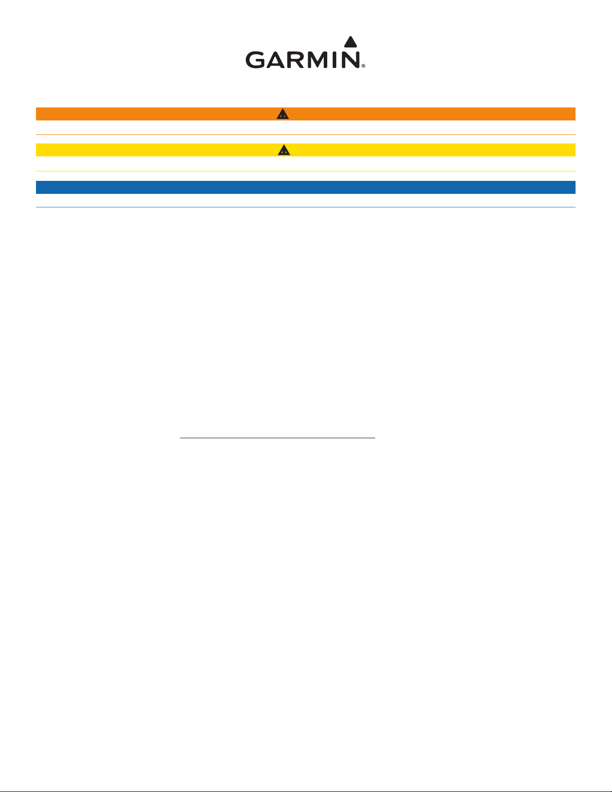
To install the GPSMAP 700 series chartplotter on the bail-mount bracket:
1. Loosely attach the mounting knobs to the GPSMAP 700 series chartplotter.
2. Slide the chartplotter onto the bail mount, and tighten the mounting knobs.
Flush Mounting the Chartplotter
Hardware (included):
• Flush-mount template
• Four 35 mm M 4.2 × 1.4 screws
Tools required (not included):
• Jigsaw
• Drill and drill bits—3/8 in. (9.5 mm) and 1/8 in. (3 mm)
• Number 2 Phillips screwdriver
• Center punch and hammer
• File and sandpaper
To ush mount a GPSMAP 700 series chartplotter:
1. The ush-mount template is included in the product box. Trim the template and ensure it will t in the location where you want to ush mount
the chartplotter.
NOTES:
Make sure the surface on which you mount the chartplotter has adequate open space behind it to t the chartplotter and the connected
•
cables, and make sure to leave approximately 1/2 in. (13 mm) of space on the right side of the chartplotter to access the SD card door and
sun cover.
To avoid interference, mount a GPSMAP 700 series chartplotter at least 32 in. (813 mm) from a magnetic compass.
•
2. The ush-mount template has adhesive on the back. Remove the protective liner and apply the template to the location at which you want to
mount the chartplotter.
3. Using a 3/8 in. (9.5 mm) drill bit, drill a pilot hole inside the corner of the template to begin cutting the mounting surface.
4. Using the jigsaw, cut the mounting surface along the inside of the solid line indicated on the ush-mount template. Use a le and sandpaper
to rene the size of the hole.
5. If the top and bottom mounting covers are attached to the front of the chartplotter, remove them by unsnapping the covers from the sides.
6. Place the chartplotter in the hole, and make sure that the mounting holes on the chartplotter line up with the pilot holes on the ush-mount
template after cutting, sanding, and ling the hole. If they do not line up, mark the locations where the pilot holes need to be.
7. Using the center punch, indent the center of each of the mounting-hole locations.
8. Using a 1/8 in. (3 mm) drill bit, drill the pilot holes.
NOTE: If you are mounting the chartplotter in berglass, it is recommended to use a countersink bit to drill a clearance-counter bore through
only the top gel-coat layer. This will help to avoid any cracking in the gel-coat layer when the screws are tightened.
9. Place the chartplotter into the cutout.
10. Securely tighten the four included 35 mm M 4.2 × 1.4 mounting screws through the chartplotter into the pilot holes.
NOTE: Stainless-steel screws may bind when screwed into berglass and overtightened. Garmin recommends applying an anti-galling,
stainless anti-seize lubricant to the screw before using.
11. Install the top and bottom mounting covers by snapping them into place.
GPSMAP 700 Series Installation Instructions 3
 Loading...