

Page 1
Owner’s
Manual &
Reference
®
Page 2

Software Version 2.05 or above
GARMIN International, Inc., 1200 E. 151st Street, Olathe, Kansas 66062 USA
Tel: 913-397-8200 Fax: 913-397-8282
GARMIN (Europe) Ltd., Unit 5, The Quadrangle, Abbey Park Industrial Estate, Romsey SO51 9AQ UK
Tel: 011-44-1794-519944 Fax: 011-44-1794-519222
GARMIN (Asia) Corp., 3F, No.1, Lane 45, Pao-Hsing Road, Hsin Tien, Taipei, Taiwan R.O.C.
Tel: 011-886-02-2917-3773 Fax: 011-886-02-2917-1758
Web Site Address: www.garmin.com
© 1997-1999 GARMIN Corporation All rights reserved. Except as expressly provided herin, no part of this manual may
be reproduced, copied, transmitted, disseminated or stored in any storage medium, for any purpose without the express
written permission of GARMIN. GARMIN Corporation hereby grants permission to download a single copy of this manual and of any revision to this manual onto a hard drive or other electronic storage medium to be viewed and to print
one copy of this manual or of any revision hereto, provided that such electronic or printed copy of this manual or revision must contain the complete text of this copyright notice and provided further that any unauthorized commercial
distribution of this manual or any revision hereto is strictly prohibited.
Information in this document is subject to change without notice. GARMIN reserves the right to change or improve its
products and to make changes in the content without obligation to notify any person or organization of such changes.
March 1999 Part # 190-00127-00 Rev. B Printed in Taiwan.
Page 3

INTRODUCTION
Thank You!
Thank you for choosing the GARMIN GPS III Pilot —the smallest, easiest-to-use GPS navigator for today’s
sophisticated aviator! The GPS III Pilot represents GARMIN’s continuing commitment to provide a quality airborne navigation system in a versatile and user-friendly flexible design you’ll enjoy for years. To get the most
from your new GPS, take the time to read through this owner’s manual in order to understand the operating
features of the GPS III Pilot. This manual is organized into three sections for your convenience:
Section One (Getting Started) introduces you to the basic features of the unit and provides a quick-start
orientation to the GPS III Pilot.
Section Two (Simulator Tour) provides a step-by-step lesson in how your new GPS III Pilot would oper-
ate in actual flight by utilizing the built-in simulator mode.
Section Three (Reference) provides details about the advanced features and operations of the GPS III Pilot
by topic.
Before getting started with your GPS, check to see that your GARMIN GPS III Pilot package includes the
following items. If you are missing any parts, please contact your dealer immediately.
Standard Package:
• GPS III Pilot Unit with Detachable Antenna
• Wrist Strap
• GPS III Pilot Owner’s Manual
• Quick Reference Card
• Velcro™ Fasteners
• Mounting Bracket
About This Manual
i
Page 4

INTRODUCTION
Cautions
!
#
CAUTION: The Global Positioning System (GPS) is operated by the government of the United States,
which is solely responsible for its accuracy and maintenance. The system is subject to changes which could
affect the accuracy and performance of all GPS equipment. Although the GPS III Pilot is a precision electronic
NAVigation AID (NAVAID), any NAVAID can be misused or misinterpreted and, therefore, become unsafe.
!
#
WARNING: For vehicular applications, it’ s the sole responsibility of the owner/operator of the GPS III Pilot
to secure the GPS unit so that it will not cause damage or personal injury in the event of an accident. For automotive use, do not mount the GPS III Pilot over airbag panels or in a place where the driver or passengers are
likely to have an impact with it in an accident or collision. The mounting hardware provided by GARMIN is
not warranted against collision damage or the consequences thereof.
!
#
WARNING: For vehicular operations, it is the sole responsibility of the operator of the vehicle to operate
his or her vehicle in a safe manner, maintain full surveillance of all conditions at all times, and never become
distracted by the GPS III Pilot to the exclusion of safe operating practices. It is unsafe to operate the GPS III
Pilot while flying or driving. Failure by the operator of a vehicle equipped with a GPS III Pilot to pay full attention to operating the vehicle while the vehicle is in motion could result in an accident.
ii
Page 5

INTRODUCTION
FCC Compliance
This device complies with Part 15 of the FCC limits for Class B digital devices. This equipment generates,
uses, and can radiate radio frequency energy and, if not installed and used in accordance with the instructions,
may cause harmful interference to radio communications. Furthermore, there is no guarantee that interference
will not occur in a particular installation.
If this equipment does cause harmful interference to other equipment, which can be determined by turning the affected equipment off and on, the user is encouraged to try and correct the interference by relocating
the equipment or connecting the equipment to a different circuit than the affected equipment. Consult an
authorized dealer or other qualified service technician for additional help if these remedies do not correct the
problem.
Operation is subject to the following conditions: (1) This device may not cause harmful interference,
and (2) this device must accept any interference received, including interference that may cause undesired
operation.
The GPS III Pilot does not contain any user-serviceable parts. Repairs should only be made by an authorized
GARMIN service center. Unauthorized repairs or modifications could void your warranty and your authority to
operate this device under Part 15 regulations.
iii
Page 6

INTRODUCTION
Limited Warranty
GARMIN Corporation warrants this product to be free from defects in materials and workmanship for one
year from the date of purchase. GARMIN will, at its sole option, repair or replace any components which fail in
normal use. Such repairs or replacement will be made at no charge to the customer for parts or labor. The customer is, however, responsible for any transportation costs. This warranty does not cover failures due to abuse,
misuse, accident or unauthorized alteration or repairs.
THE WARRANTIES AND REMEDIES CONTAINED HEREIN ARE EXCLUSIVE AND IN LIEU OF ALL
OTHER WARRANTIES EXPRESSED OR IMPLIED, INCLUDING ANY LIABILITY ARISING UNDER WARRANTY OF MERCHANTABILITY OR FITNESS FOR A PARTICULAR PURPOSE, STATUTORY OR OTHERWISE.
THIS WARRANTY GIVES YOU SPECIFIC LEGAL RIGHTS, WHICH MAY VARY FROM STATE TO STATE.
IN NO EVENT SHALL GARMIN BE LIABLE FOR ANY INCIDENTAL, SPECIAL, INDIRECT OR CONSEQUENTIAL DAMAGES, WHETHER RESULTINGFROM THEUSE, MISUSE ORINABILITY TOUSETHIS
PRODUCT OR FROM DEFECTS IN THE PRODUCT. SOME STATES DO NOT ALLOW THE EXCLUSION OF
INCIDENTAL ORCONSEQUENTIAL DAMAGES, SOTHEABOVELIMITATIONSMAY NOT APPLYTOYOU.
To obtain warranty service, call the GARMIN Customer Service department (913-397-8200) for a returned
merchandise tracking number . The unit should be secur ely packaged with the tracking number clearly marked on
the outside of the package, and sent freight prepaid and insured to a GARMIN warranty service station. A copy of
the original sales receipt is required as the proof of purchase for warranty repairs. GARMIN retains the exclusive
right to repair or replace the unit or software or offer a full refund of the purchase price at its sole discretion. SUCH
REMEDY SHALL BE YOUR SOLE AND EXCLUSIVE REMEDY FOR ANY BREACH OF WARRANTY.
iv
Page 7

INTRODUCTION
Table of Contents
INTRODUCTION
About This Manual . . . . . . . . . . . . . . . . . . . .i
Cautions . . . . . . . . . . . . . . . . . . . . . . . . . . .ii
FCC Compliance . . . . . . . . . . . . . . . . . . . . .iii
Limited Warranty . . . . . . . . . . . . . . . . . . . . .iv
GETTING STARTED
Unit Features . . . . . . . . . . . . . . . . . . . . . . . .1
Keypad Usage / Display . . . . . . . . . . . . . . . . .2
Battery Installation . . . . . . . . . . . . . . . . . . . .3
What is GPS? . . . . . . . . . . . . . . . . . . . . . . . .4
Initialization . . . . . . . . . . . . . . . . . . . . . . . . .5
Main Page Sequence . . . . . . . . . . . . . . . . . . .7
Satellite Status Page . . . . . . . . . . . . . . . . . . .8
Position Page . . . . . . . . . . . . . . . . . . . . . . . .9
Map Page . . . . . . . . . . . . . . . . . . . . . . . . . .10
HSI Page . . . . . . . . . . . . . . . . . . . . . . . . . .11
Highway Page . . . . . . . . . . . . . . . . . . . . . . .12
Main Menu . . . . . . . . . . . . . . . . . . . . . . . . .13
Viewing Database Info . . . . . . . . . . . . . . . .14
Going to a Waypoint . . . . . . . . . . . . . . . . . .15
Cancel GOTO / Active Route . . . . . . . . . . . .16
SIMULATOR TOUR . . . . . . . . . . . . . . . . . . .17
REFERENCE
Satellite Status Page . . . . . . . . . . . . . . . . . .27
Position Page . . . . . . . . . . . . . . . . . . . . . . .32
Map Page . . . . . . . . . . . . . . . . . . . . . . . . . .35
HSI Page . . . . . . . . . . . . . . . . . . . . . . . . . .40
Vertical Navigation . . . . . . . . . . . . . . . . . . .44
Highway Page . . . . . . . . . . . . . . . . . . . . . . .46
Waypoint Categories . . . . . . . . . . . . . . . . . .48
Nearest Page . . . . . . . . . . . . . . . . . . . . . . . .53
User Waypoints . . . . . . . . . . . . . . . . . . . . .55
GOTO . . . . . . . . . . . . . . . . . . . . . . . . . . . .61
TracBack . . . . . . . . . . . . . . . . . . . . . . . . . .64
Routes . . . . . . . . . . . . . . . . . . . . . . . . . . . .66
Active Route Page . . . . . . . . . . . . . . . . . . . .70
v
Page 8

INTRODUCTION
Table of Contents
Main Menu . . . . . . . . . . . . . . . . . . . . . . . . .73
Setup Functions . . . . . . . . . . . . . . . . . . . . .76
APPENDIX A: Mounting Instructions . . . . . . . .88
APPENDIX B: Specifications . . . . . . . . . . . . . . .90
APPENDIX C: Wiring/Interfacing . . . . . . . . . . .91
APPENDIX D: Antenna/Remote Mounting . . . . .92
APPENDIX E: Messages . . . . . . . . . . . . . . . . . .93
APPENDIX F: Map Datums . . . . . . . . . . . . . . .95
APPENDIX G: Navigation Terms . . . . . . . . . . . .98
APPENDIX H: Index . . . . . . . . . . . . . . . . . . .100
vi
Page 9

To change the screen
orientation, press and
hold the PAGE key.
GETTING STARTED
Unit Features
Antenna
(detachable)
Function Keys
Power/Backlight
Key (red)
Rocker Keypad
LCD Display
Battery Door
1
Page 10
GETTING STARTED
Keypad Usage/Display
(POWER)— Red key turns the unit on and off, and
controls three levels of screen backlighting intensity.
(PAGE)— Scrolls main pages in sequence and returns
display from a menu/options page to a main page.
Press and hold this key to change screen orientation.
(MENU)— Displays a menu of available options for
the current page. Press twice to display the Main Menu.
(GOTO/
NRST
dow, allowing you to select the destination waypoint.
Press and hold this key to display the nine nearest airports, airspaces, navaids, waypoints, etc.
(ENTER/
confirms menu options and data entry. Press and hold
this key to mark present position as a waypoint.
(QUIT)— Returns the display to a previous page or
restores a data field’s previous value.
(IN and OUT)— Allows you to zoom in/out through
23 scales on the Map Page. Also adjusts scale on the
Highway and HSI pages.
(ROCKER KEYPAD)— Controls the movement of
the cursor, is used to select options and positions, and
to enter data.
2
)— Displays the GOTO waypoint win-
MARK
)— Activates highlighted fields and
CURSOR— A solid black bar which can be moved
up, down, left, and right with the keypad to select individual fields on the display (see above).
DEFAULT— A system-selected format, built into the
operating software or the unit’s memory, that will be
followed unless the user chooses a different setting.
FIELD— The location on a page (see above) where a
group of characters or option is entered and displayed.
HIGHLIGHT— The act of using the cursor to select a
field for the purpose of entering data.
SCROLL— The act of moving through characters or
options from a selected field.
DATA ENTRY— Entering data, such as waypoint
names, typically begins and ends with the ENTER/
MARK key. Use the rocker keypad to enter the actual
data: UP/DOWN to change the highlighted character,
RIGHT to move on to the next character.
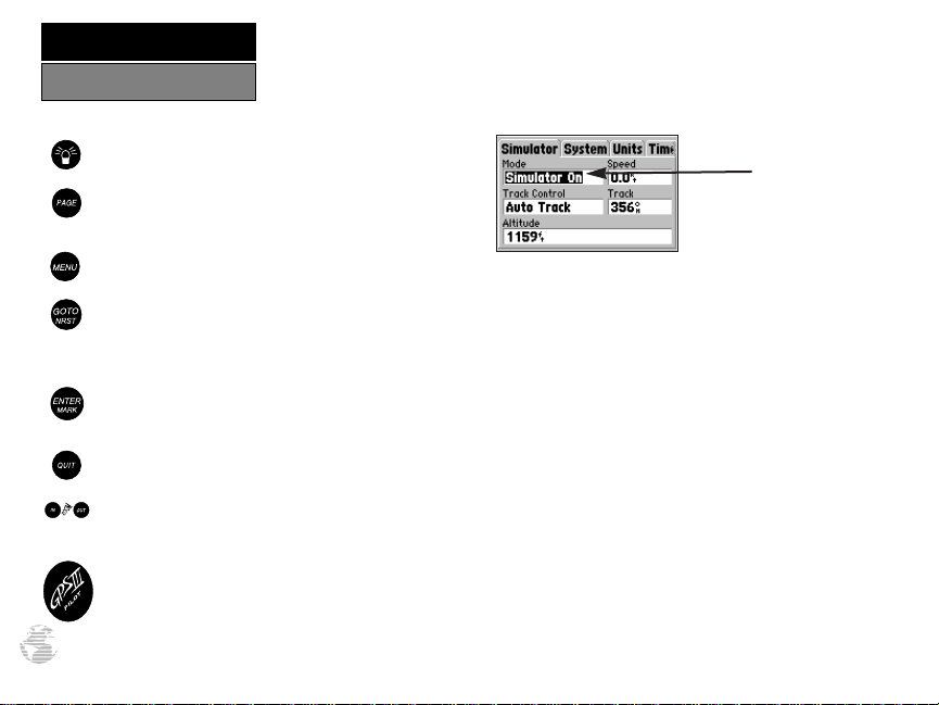
Example of
Cursor highlighting the
‘Mode’ Field
Page 11
The GPS III Pilot operates on 4 AA batteries, which are installed at the base of
the unit. These batteries provide up to 24 hours of continuous use. Rechargeable
NiCad or lithium batteries may also be used.
?
NOTE: The on-screen battery level indicator is calibrated for alkaline batteries,
and will not be accurate when using NiCad or lithium batteries (see page 79).
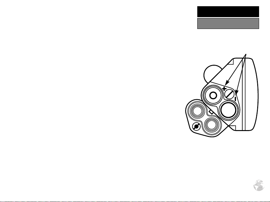
To install the batteries:
1. Flip up the metal ring at the base of the unit, and turn the ring 90˚ counterclockwise.
2. Install the batteries and close the battery compartment door. When replacing the
GPS III Pilot’s batteries, observe the polarity markings engraved in the plastic
case.
3. Lock the door in the closed position by rotating the metal ring 90˚ clockwise.
Battery life varies due to a variety of factors, including temperature and
backlighting. You may find that the battery life varies in different conditions and
that lithium batteries provide longer life in colder conditions. An internal 10year lithium battery will retain your data while you’re changing batteries.
#
GETTING STARTED
Battery Installation
Polarity
Markings
3
Page 12

GETTING STARTED
What is GPS?
Hold the receiver at a
comfortable height with the
antenna pointing up.
When new (or if a position
cannot be determined after 10
minutes), the GPS IIIPilot will
prompt you to initialize the
receiver. The unit needs a
starting position to determine
4
which satellites are in view.
The Global Positioning System (GPS) is a system of 24 satellites which circle the
earth twice a day in a very precise orbit and transmit information to earth. The GPS
III Pilot must continuously “see” at least three of these satellites to calculate your
position and track your movement. At times, additional satellites may be needed to
determine a position.
By using an almanac (a timetable of satellite numbers and their orbits) stored in
the receiver’s memory, the GPS III Pilot can determine the distance and position of
any GPS satellite and use this information to compute your position.
Your GPS receiver can only see satellites above the horizon, so it needs to know
what satellites to look for at any given time. To use this almanac data, your GPS
needs to either be told its general location (“initialized”) or given the opportunity to
find itself. Once you initialize the unit to a position, it will typically compute a fix within a few minutes. We’ll show you how to initialize your new GPS III Pilot on page 5.
Initialization is only necessary under the following conditions:
• The first time you use your receiver (new from the factory).
• After the receiver has been moved over 500 miles (with the power off) from
the last time you used it.
• If the receiver’s memory has been cleared and all internally stored data has
been lost.
Because the GPS III Pilot relies on satellite signals to provide you with navigation
guidance, the receiver needs to have an unobstructed, clear view of the sky for best
performance. In a nutshell, the GPS receiver’s view of the sky will generally determine
how fast you get a position fix—or if you get a fix at all. GPS signals are relatively
weak and do not travel through rocks, buildings, people, metal, or heavy tree cover,
so remember to keep a clear view of the sky at all times for best performance.
Page 13
GETTING STARTED
Once the GPS III Pilot has calculated a position fix, you’ll usually have anywhere
from five to twelve satellites in view. The receiver will then continuously select the best
satellites in view to update your position. If some of the satellites in view get blocked
or “shaded,” the receiver can simply use an alternate satellite to maintain the position
fix. Although a GPS receiver needs four satellites to provide a three-dimensional
(3D) fix, it can maintain a two-dimensional (2D) fix with only three satellites. A
three-dimensional fix means the unit knows its latitude, longitude, and altitude, while
a two-dimensional fix means the unit knows only its latitude and longitude.
Initializing Your GPS III Pilot
To initialize the GPS III Pilot, take the receiver outside and find an open area where
the antenna has a clear view of the sky. You may either hold the receiver at a comfortable height with the antenna pointing up (see page 4), or mount the receiver on the
dash of a vehicle, as described in Appendix A. (Likewise, when you use your GPS III
Pilot in a vehicle, make sure the antenna is pointing up.)
To turn the GPS III Pilot on, press and hold the red power key.
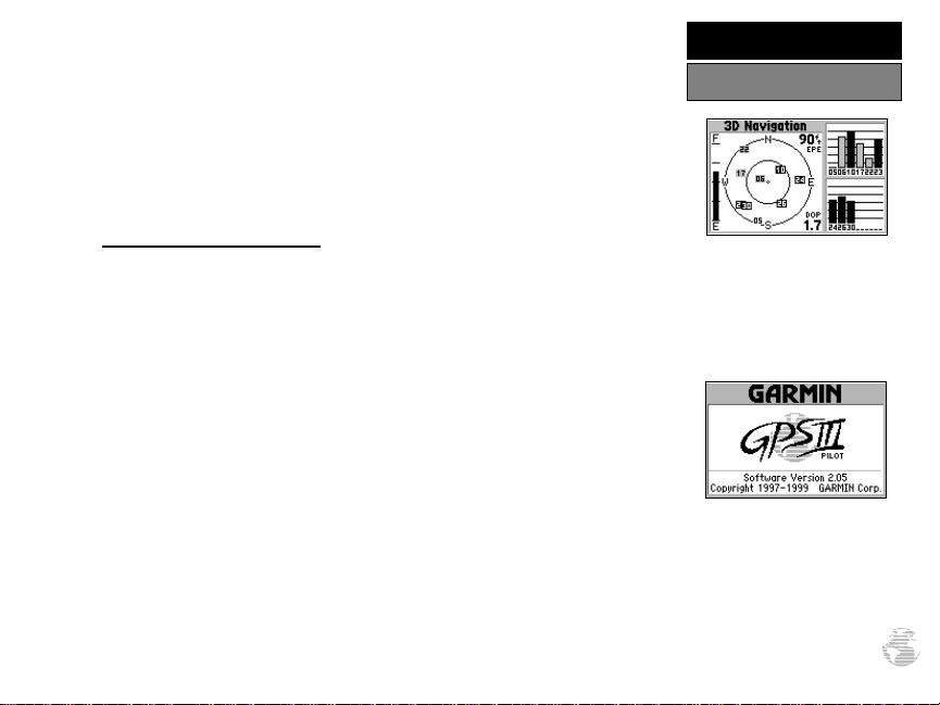
The Welcome Page will be displayed while the unit conducts a self test. Once
testing is complete, the Welcome Page is replaced by the Database Page (which shows the
effective date for the Jeppesen database), followed by a warning page, then by the Satellite
Status Page. A message will inform you to “select initialization method.” (If the initialization prompt has not automatically appeared, press MENU and select ‘Initialize Position’.)
To initialize your unit:
1. Press ENTER to acknowledge the message. A window will appear prompting you to
select an initialization method.
2. Use the rocker keypad to highlight ‘Use Map’, and press ENTER.
3. Use the rocker keypad to point the map cursor to your approximate location (within at
least 250 miles). You may also wish to use the IN and OUTzoom keys to make it easier to
identify your approximate position.
4. Press ENTER to select the position and begin searching for satellites.
Initialization
Check the Satellite Status
Page for ‘2D Navigation’ or
‘3D Navigation’ to verify a
position fix.
The Welcome Page is
displayed when the GPS III
Pilot is first turned on. During
this time the receiver is conducting a self-test.
5
Page 14

GETTING STARTED
Initialization
To initialize the GPS III Pilot,
designate your approximate
location directly on the map
display. Use the rocker keypad
and IN/OUT zoom keys to
position the cursor on the map.
Once the GPS III Pilot has a
position fix, it will automatically transition from the
Satellite Status Page to the
Map Page.
6
This usually provides a position fix in one minute. You’ll know you have a fix
when the unit automatically transitions from the Satellite Page to the Map Page
(shown bottom left). Your receiver is now ready to use!
To turn the unit off:
1. Press and hold the red power key for one second.
Troubleshooting
If you have trouble initializing or getting a position fix, check the following:
• Does the receiver have a clear view of the sky?
If there are large buildings or mountains, or if there is heavy tree cover, the receiv-
er may not be receiving enough satellite signals to calculate a fix. Also, if you’re
using the GPS III Pilot inside the cockpit, make sure the unit is placed so that it
has the clearest possible view of the sky. Your GPS will only be able to detect satel-
lites that it can “see” through your vehicle’s windshield. Depending on the slope
of glass or the overall surface area, it may be necessary to remote mount an anten-
na inside the cockpit or install an outside antenna. (Contact your local GARMIN
dealer and inquire about the GA 26 Remote Antenna, part number 010-10052-
02, or the GA 56 Low Profile Antenna, part number 010-10040-01.)
• Have you selected the right area when initializing?
Check for the correct approximate position on the Map Page (press PAGE until
the Map Page appears; see pages 7 and 10), or reselect your approximate
location to restart the initialization.
• Have you moved more than 500 miles from the last calculated position
with the receiver off?
Reinitialize the receiver by selecting your approximate position on the map, or
select ‘AutoLocate’ from the Satellite Status Page Options (see page 31).
Page 15
GETTING STARTED
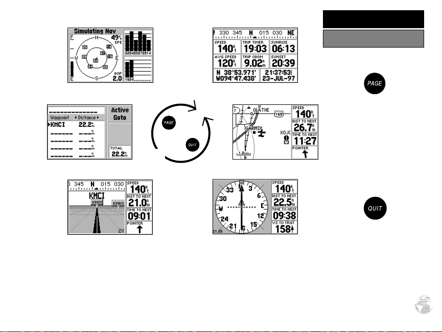
Main Page Sequence
Position PageSatellite Status Page
Press the PAGE key to move
through each of the main
pages in normal fashion.
Map PageActive Route Page
Highway Page
To turn the GPS III Pilot back on, press and hold the red power key.
The GPS III Pilot features six main pages which are linked together in a chain. You
HSI Page
Press the QUIT key to
sequence through the main
pages in reverse order.
can quickly scroll through the pages in either direction using the PAGE or QUIT keys.
Let’s briefly tour each of these pages in order to give you some insight into how they
help you navigate. We’ll go over all of them in more detail in the reference section.
7
Page 16
GETTING STARTED
Satellite Status Page
The signal strength bars give
you an indication of what
satellites are visible to the
receiver, whether or not they’re
being used to calculate a position fix, and the signal quality.
Let’s start with the Satellite Status Page, which is the page you’ll view while your
unit is getting a position fix. If you’re not already on this page, press PAGE or QUIT
until it appears. The Satellite Status Page shows you status information that helps
you understand what the receiver is doing at any given time, and it’s a page that
you’ll want to occasionally refer back to as you use your unit. It features a sky view
of available satellites, corresponding signal strength bars, the status of your current
position fix (acquiring, 2D, 3D, etc.), and your estimated position error (EPE). You
can also tell how much battery power is remaining, and you can adjust the screen
contrast by pressing the rocker keypad.
Satellites are indicated on the sky view and the signal strength bars by their corresponding number, from 01 through 32. The sky view shows where it is looking in
the sky for each satellite, by indicating the direction and elevation (angle above the
horizon). The signal strength bars depict the relative strength of the signal from each
satellite being received. The taller the bar, the stronger the signal.
If satellite reception is lost, or
an insufficient number of
satellites are available, you
will be alerted with a ‘Poor
Coverage’ receiver status and
message.
8
Receiver Status
Battery Level
Indicator
Signal Strength Bar
Sky View
Satellite Status Page
Page 17
GETTING STARTED
The Position Page shows you where you are, what direction you’re heading, and
how fast you’re going—and it’s a page you may want to use when you don’t have a
destination selected.
A graphic compass display at the top of the page shows your direction of travel
(track) while you’re moving, while six user-selectable data fields below display your
current speed, average speed, trip odometer, trip timer, and sunrise/sunset times at
your current position. “User-selectable” means you can change them to display other
navigation information. We’ll cover these fields more in the reference section.
Below the user-selectable data fields are additional data fields to display your
current position, along with current time and date. The current position readout can
be in latitude/longitude, UTM/UPS, Maidenhead or one of several regional grids.
Current time and date can be in local time or UTC (Coordinated Universal Time, or
“zulu” time).
Position Page showing current
position in degrees, minutes
and seconds.
Position Page
Track Compass
Current Position
Coordinates
Position Page
Trip Odometer
Current Time
and Date
The trip odometer, trip timer
and average speed readings
can all be reset from the ‘Trip
Computer’ option on the Main
Menu. See page 75.
9
Page 18

GETTING STARTED
Map Page
With the map oriented to
‘Track Up’, the pointer always
points up and the map rotates
to your current direction of
travel (track). Note the north
indicator on the map.
The Map Page shows your movement using a real-time track log (an electronic
breadcrumb trail that appears directly on the map as you’re traveling), and your
present position as an airplane icon in the center of the map. The Map Page also
shows any nearby airspace boundaries, lakes, rivers, highways and towns. The map
scale is shown in the lower left-hand corner of the map. Use the zoom keys (IN and
OUT) to adjust the map to the desired scale.
To change the map scale:
1. Press the IN zoom key to select a smaller scale and more detail for a smaller area.
2. Press the OUT zoom key to select a larger scale and display a larger area.
The map can be oriented with the top of the page always pointing north,
oriented along your desired course, or it can automatically rotate to keep your
current direction of travel (track) at the top of the screen. ‘North Up’ is the default
setting.
Nearby airports, VORs, NDBs, intersections and user waypoints are depicted on
the map (each with its own unique symbol) with the identifier listed directly above
the waypoint’s symbol. We’ll cover more about the GPSIII Pilot’s waypoint features
and the Map Page in the reference section of this manual.
You can also select a fullscreen map from the Map
Page Options. See page 37.
10
Nearby Navaid
(Intersection)
Present Position
Data Fields
Nearby Airport
Map Page
Page 19

GETTING STARTED
The GPS III Pilot features two different navigation pages: HSI (horizontal situation
indicator) and Highway. The HSI Page is first. The HSI Page provides graphic steering
guidance to a destination waypoint and will likely become your primary navigation
screen. (The Highway page also provides graphic steering guidance by displaying a
three-dimensional perspective of your course and the surrounding area.) The HSI
graphically depicts a mechanical HSI, showing the desired course using a ‘D-bar’
(course deviation bar; which is part of the course deviation indicator, or ‘CDI’) and
course pointer. If you move off course, the D-bar will indicate off course distance and
direction. To return to the desired course, simply steer in the direction of the D-bar
until it returns to the center of the CDI. The CDI scale is adjustable, with the current
scale indicated at the bottom of the page. The scale setting represents the distance from
the center of the CDI to full left or right limits.
The HSI depicts your (ground) track heading using a rotating ‘compass card’.
Don’t confuse this with the aircraft heading indicated on your panel. On a windy day
these two figures can differ significantly!
The HSI page also provides a TO/FROM indication and vertical guidance, when
using the unit’s vertical navigation (VNAV) features. Four user-selectable data fields
indicate current speed, distance to destination, time en route and time of day.
Pointer
(Desired Course)
D-bar
(part of CDI)
Compass Card
(Track)
HSI Page
Current Speed
and Distance to
Waypoint
Time to Waypoint
If you move off course, steer
in the direction of the D-bar
until it returns to the center of
the CDI.
The ‘Big Numbers’ option
(available from the HSI Page
Options) shows a smaller
compass-type display and
larger data field characters.
See page 42.
HSI Page
11
Page 20

GETTING STARTED
Highway Page
If you move off course, the
highway display will move,
indicating the direction you
are off course. To stay on
course, simply move toward
the center of the highway.
The GPS III Pilot’s Highway Page also provides graphic steering guidance to a
destination waypoint. As you head toward your destination, the middle of the screen
provides visual guidance to your waypoint on a moving graphic “highway.” Your present position is at the bottom center of the highway display. The line down the middle of the highway represents your desired course. As you navigate toward a waypoint, the highway will actually move—indicating the direction you’re off course. To
stay on course, simply move toward the center of the highway.
The top of the page indicates speed and distance to your destination (or the next
waypoint in a route), along with a track compass showing current direction of
travel. Directly below the distance reading is the time required to reach your destination (or the next waypoint in a route), in hours/minutes or minutes/seconds. The
pointer at the bottom of the page also shows the bearing to your destination, relative
to your current track. If the pointer points straight ahead, you’re heading directly to
your destination!
As you approach your destination, the graphic highway
will stop at the destination
waypoint. You have arrived
when the waypoint is at the
bottom center of the display.
12
Track Compass
Highway Display
Highway Page
Distance to
Destination (or Next
Route Waypoint)
Pointer
(Bearing to
Destination)
Page 21
GETTING STARTED
The GPS III Pilot’s Main Menu provides access to an additional set of pages that
are used to create or edit waypoints, create routes, review track log or trip information,
configure the vertical navigation features, perform E6B calculations or make changes
to system settings. These seven menu items are divided into categories by function.
The waypoint and route management features of the Main Menu are described in more
detail in the Reference section of this manual. Let’s take a look at the Main Menu and
one of its options.
To view the Main Menu:
1. Press the MENU key twice.
To select an item from the Main Menu:
1. Highlight the desired item using the rocker keypad, and press ENTER.
2. To return to the Main Menu, press QUIT.
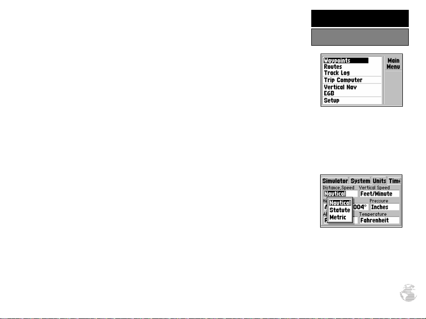
The ‘Setup’ option provides a list of choices (presented as a series of ‘file tabs’) to
perform various configuration settings including system settings, selection of position
format and units of measure, time display, setting various alarms, enabling the built-in
simulator feature and interface options with other equipment:
To change units of measure for distance and speed:
1. Select the ‘Setup’ option from the Main Menu (as described above), and press ENTER.
2. Highlight the ‘Units’ tab with the rocker keypad. The units settings are automatically
displayed.
3. Highlight the ‘Distance & Speed’ field using the rocker keypad, and press ENTER.
A pop-up menu appears showing the available options.
4. Select the desired option using the rocker keypad, and press ENTER.
Main Menu
The Main Menu provides
access to additional pages,
including database information, flight
information and unit settings.
The ‘Setup’ option provides a
list of menu choices to perform various configuration
settings, such as changing
units of measure for distance
and speed.
plans (routes), trip
13
Page 22

GETTING STARTED
Viewing Database Info
To view database information
directly from the map, place
the panning cursor on the
desired item and press
ENTER.
To view database information
by manually entering the
identifier, name or city, select
the ‘Waypoints’ option from
the Main Menu.
14
One of the most important features of the GPS III Pilot is the built-in Jeppesen
database, which includes information on airports, runways, communication frequencies, VORs, NDBs, intersections and airspace boundaries. This information is readily
available directly from the map, or from the ‘Waypoints’ option on the Main Menu.
To view the database information from the Map Page:
1. With the Map Page displayed, use the rocker keypad to place the panning cursor
over the desired facility on the map. When the cursor is directly over the desired
item, the identifier for that item is highlighted. (For airspace information, place the
cursor over any open area within the boundary of the desired airspace.)
2. Press ENTER to view the database information for the selected facility/airspace. If
an airport was selected, use the rocker keypad to select the ‘Airport’, ‘Runway’ or
‘Comm’ information pages for that airport.
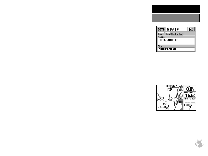
To view the database information by entering the identifier, name or city
for the desired facility:
1. Press MENU twice to display the Main Menu.
2. Highlight ‘Waypoints’ and press ENTER. A series of tabs appear for each category of
waypoint information: airports, runways, comm frequencies, VORs, NDBs, intersections, user-entered waypoints. Select the desired category using the rocker keypad.
3. To view information by identifier, highlight the identifier field and press ENTER. Enter
the identifier, using the rocker keypad, and press ENTER to display the information.
4. To view information by facility name or city (only applicable to the ‘Airport’, ‘VORs’, and
‘NDBs’ information pages), highlight the appropriate field and press ENTER.
name/city using the rocker keypad, and press ENTER to display the information.
Enter the
Page 23
GETTING STARTED
The GPS III Pilot’s GOTO feature allows you to quickly and easily navigate to any
airport, navaid or user-entered waypoint stored in memory. A GOTO is really nothing
more than a straight-line course from your present position to the destination you’ve
selected. A GOTO can be performed several ways: by specifying the destination from
the GOTO Page, graphically from the map display or by highlighting the waypoint
name on any page (such as the Nearest Page).
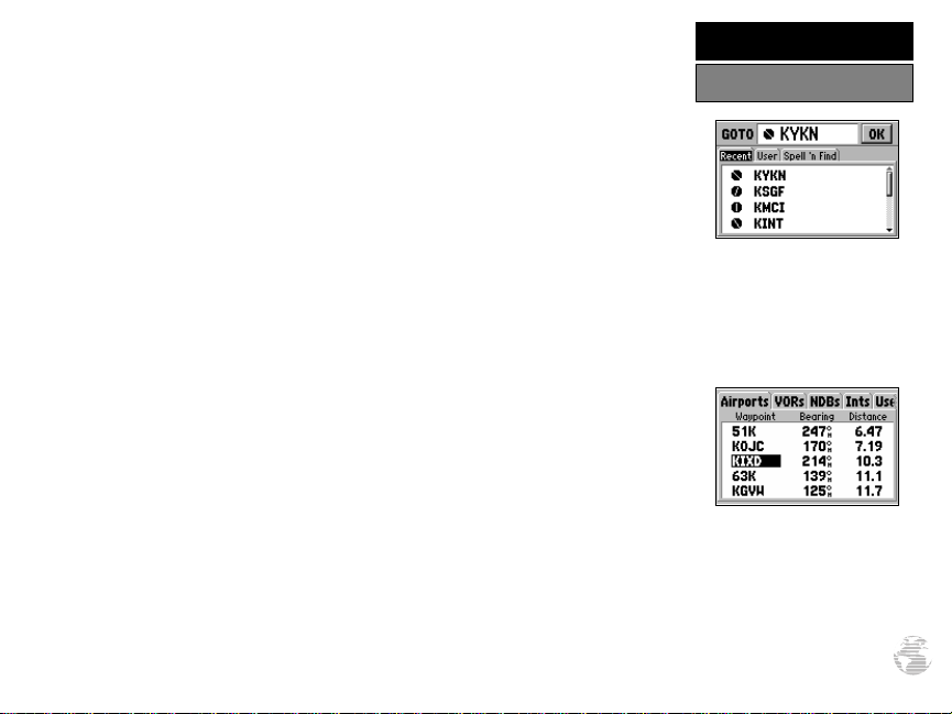
To select a GOTO destination from the GOTO Page:
1. Press GOTO/NRST. This captures your current position as the starting point for your trip.
2. Highlight the identifier field at the top of the page and press ENTER. This allows you to
enter the identifier for any waypoint position stored in memory.
3. Use the rocker keypad to enter the identifier for the desired waypoint and press ENTER.
To select a GOTO destination from the Map Page:
1. With the Map Page displayed, use the rocker keypad to place the cursor over the
desired destination waypoint. (If no waypoint exists at the destination location, the GPS
III Pilot will automatically create one, named ‘MAP’ in the step below.)
2. Press GOTO/NRST, and then ENTER to navigate to the selected location.
To GOTO a listed waypoint on the Nearest Page:
1. Press and hold the GOTO/NRST key to display the Nearest Page.
2. Use the rocker keypad to select a tab for the desired waypoint category (e.g. ‘Airport’).
3. Use the rocker keypad to highlight the desired waypoint, press GOTO/NRST and ENTER.
Once the GOTO destination is selected, use the Map Page, HSI Page and/or
Highway Page to keep track of your progress as you head toward your destination.
To select the GOTO destination from a list of all user
waypoints or from a list of
recently used waypoints, select
the ‘User’ or ‘Recent’ tabs.
To GOTO one of the listed
‘Nearest Waypoints’, highlight
the desired waypoint, press
GOTO/NRST and then
ENTER.
Going to a Waypoint
15
Page 24
GETTING STARTED
Cancel GOTO/Active Route
To cancel the current GOTO
destination, select ‘Cancel
GOTO’ from the GOTO
Options Page.
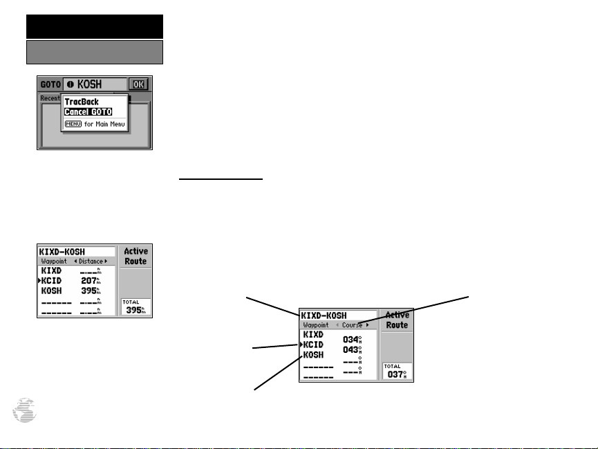
To cancel the current GOTO destination, simply select another destination. If no
destination is currently desired, or you want to resume a previously selected route,
the GOTO operation may be cancelled from the GOTO Options Page.
To cancel the current GOTO destination:
1. Press GOTO.
2. Press MENU.
3. Highlight ‘Cancel GOTO’ and press ENTER.
Active Route Page
The last of the six main pages is the Active Route Page. This page shows the
GOTO waypoint or each waypoint of a route, with waypoint name and the course
along each leg (segment) of the route. When using a route, the current destination is
marked with an arrow on the left-hand side of the screen. If no destination has been
specified using the GOTO key or a route, no waypoints will be listed on
the page.
(For more information on using routes, see page 66 in the Reference section.)
Use the LEFT/RIGHT keys on
the rocker keypad to select the
desired data item. Available
items include course, distance,
fuel, and sunrise/sunset times.
16
Route Name
Field
Current Destination
Waypoint Name
Selectable Field,
showing Course to
this Waypoint from
Previous Waypoint
(or start of GOTO)
Active Route Page
Page 25

SIMULATOR TOUR
The GPS III Pilot is a powerful navigation system providing detailed mapping
information in a convenient, compact package. This simulator tour is designed to show
you the basic features of your new GPS III Pilot during a simulated trip. The simulator
tour assumes that the receiver has been properly initialized as outlined in the Getting
Started section of this manual, and that you have not changed any of the factory default
settings. If you have changed any settings (position formats, units of measure, etc.), the
descriptions and pictures in the tour may not match your configuration.
Once you’re familiar with the primary functions of the GPS III Pilot, you’ll be ready
to use your new receiver on a real trip to a destination of your choice. The Reference
section of this manual may be consulted for any additional questions you may have, or
to learn about the more advanced features of the GPS III Pilot. For now, let’s get started on the Simulator Tour!
If the GPS III Pilot is currently off, you’ll need to start by turning it on.
To turn the GPS III Pilot on, press and hold the red power key.
The Welcome Page will be displayed while the unit conducts a self test. Once testing is complete, the Welcome Page is replaced by the Database Page, then by a warning page, and finally by the Satellite Status Page. Since we’ll be using the simulator
mode, we don’t need to wait for the receiver to acquire satellites.
Selecting Simulator Mode
The Welcome Page is displayed
when the GPS IIIPilot is tur ned
on. After a brief self-test, it is
replaced by database and
warning pages. To skip these
pages, press ENTER.
!
WARNING: Keep in mind that the GPS III Pilot does not track satellites in
simulator mode and this mode should never be used for actual navigation. The GPS III
Pilot cannot be turned on in simulator mode. If you forget to change back to normal
operation before shutting the receiver off, it will automatically return to normal mode
the next time you use the receiver.
#
The Satellite Status Page
appears next. For simulator
mode operations, there’s no
need to wait for the GPS III
Pilot to acquire satellites.
17
Page 26
SIMULATOR TOUR
Selecting Simulator Mode
Select ‘Start Simulator’ from
the Satellite Status Page
Options to enable the built-in
simulator.
The simulator imitates satellite reception and shows that
information on the Satellite
Status Page. Remember, in
this mode the GPS IIIis not
actually tracking satellites.
18
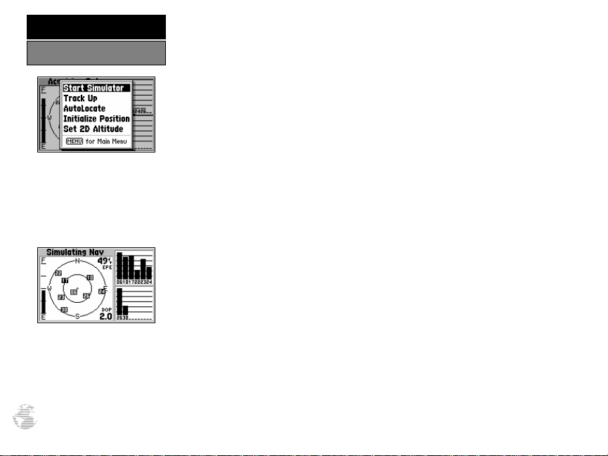
To select the simulator mode:
1. Press MENU to list the options for the Satellite Status Page.
2. Highlight ‘Start Simulator’ with the rocker keypad, and press ENTER.
3. Press ENTER to acknowledge the warning message.
Let’s look at the sequence of pages again. The PAGE and QUIT keys are used to
find your way around on the GPS III Pilot.
To cycle through the main pages:
1. Press PAGE to move through each of the main pages in normal fashion.
2. Press QUIT to sequence through the main pages in reverse order.
In normal mode operation, the GPS III Pilot would automatically sequence from
Satellite Status Page to Map Page once enough satellites where received to determine
your position. At that point the receiver is ready to use for navigation. Since we’re
in simulator mode we won’t see that automatic sequence of steps, but as you cycle
through the main pages, notice that the simulator imitates satellite reception and
shows that information on the Satellite Status Page.
The Position Page will show the last known position as a starting location. If
you’ve already initialized the receiver, as outlined in the Getting Started section, the
starting location should be very close to your current position! We’ll use this starting location from which to begin our simulated trip. Let’s move on to the Map Page
to see where we are, select a GOTO destination and explore the navigation features
of the GPS III Pilot.
To select the Map Page, press PAGE repeatedly until it appears.
Page 27

The GPS III Pilot’s Map Page combines digital charts and Jeppesen data with a
number of user-selectable features. Before we select our destination and begin navigating toward it, let’s take a look at some of those features.
SIMULATOR TOUR
Using the Map Page
Background Cities,
Roads and Lakes
Current Scale
Setting
The map display shows your present position using an airplane icon in the center
of the screen. The Map Page also shows any nearby airports, navaids, airspace boundaries, lakes, rivers, highways and towns. Use the zoom keys (IN and OUT) to adjust
Present Position
Nearby Airport
In the ‘Track Up’ orientation,
the map is automatically
rotated to keep your current
direction of travel at the top
of the screen. Note the north
indicator in upper-left corner.
the map to the desired scale. The current scale is indicated in the lower-left corner.
To change the map scale:
1. Press the IN zoom key to select a smaller scale and display a smaller geographic area.
2. Press the OUT zoom key to select a larger scale and display a larger geographic area.
The map can be oriented with the top of the page always pointing north (‘North
Up’), oriented along your desired course (‘Course Up’), or it can automatically rotate
to keep your current direction of travel at the top of the screen (‘Track Up’).
Let’s try panning around on the map display to see how that process works, and
then we’ll find a nearby airport, VOR, NDB or intersection and navigate to it. First we
will need to select an appropriate map scale to begin our search.
Use the IN/OUT zoom keys
to change the map scale. The
current scale appears in the
lower-left corner of the map
display.
Select a five nautical mile scale by pressing zoom IN or OUT repeatedly.
19
Page 28

SIMULATOR TOUR
Viewing Waypoint Info
Use the rocker keypad to pan
to other areas on the map
display. When panning, an
on-screen cursor appears for
reference.
Working from the Map Page is a simple process that centers around the use of
the cursor. Controlled by the rocker keypad, the cursor is an important tool allowing you to pan to other areas on the map display, view waypoint information, create
waypoints, specify a GOTO target and create routes. To get a feel for using the Map
Page and the cursor, try the following exercise:
1. Using the rocker keypad to move the cursor, try following a highway (or other feature) near your position. Simply press and hold one side of the rocker keypad to
move more quickly. Notice how a data field appears above the map, showing the
bearing and distance from present position to the cursor, along with the latitude/
longitude of the cursor.
2. Using the rocker keypad, continue moving the cursor in any direction until you find
an airport or navaid. Once you find one, place the cursor over that waypoint so that
its identifier is highlighted.
3. Press ENTER to view the database information for the selected waypoint. If an airport is selected, use the LEFT/RIGHT keys on the rocker keypad to select between
‘Airport’, ‘Runway’ and ‘Comm’ information pages.
Place the cursor over an onscreen airport or navaid to
highlight the item, then press
ENTER to view database
information for the selected
item.
20
‘File Tabs’ for
other info types
Waypoint
Identifier Field
4. When finished reviewing the information press QUIT to return to the Map Page.
(Pressing QUIT a second time will end the panning operation and return the map to
your present position. For now, we’ll stay in panning mode and leave the selected
waypoint highlighted on the map.)
Waypoint
Symbol Field
Waypoint Position
Page 29
SIMULATOR TOUR
Now that we’ve seen how to find waypoints on the map and view information
about them, let’s see how the GPS III Pilot is used to navigate to the waypoint we just
selected. (Keep in mind that the cursor can also be used to GOTO any point on the
map–even without a waypoint already at that location–by simply panning to a location
and pressing GOTO/NRST. A waypoint named ‘MAP’ is automatically created. We
won’t try that here, but you might want to experiment with this procedure at the end
of the Simulator Tour.)
To select the highlighted waypoint as a GOTO destination, press GOTO/
NRST and ENTER.
Notice that a course line appears on the map display showing the way to our
destination, panning mode is automatically cancelled and the map re-centers itself
around your present position. Now that we have our destination selected, it’s about
time we get started—so let’s plug a speed into this simulator to animate the displays!
To enter a simulated speed and animate the displays:
1. Press PAGE repeatedly until the HSI Page appears (see page 22).
2. Enter a simulated speed of ‘100’ (knots) using the rocker keypad. (Press UP on the rocker keypad repeatedly to select ‘100’. The speed readout is on the upper-right corner of
the HSI Page.)
3. Press PAGE (or QUIT)repeatedly to return to the Map Page.
Notice the information on the map display is slowly moving? That’s how it would
look in actual use as well. The background map information, airports, navaids and airspace boundaries will move across the screen, while your current position remains
fixed in the center.
Going to the Waypoint
To select a GOTO destination
from the map, highlight the
desired waypoint, press
GOTO/NRST and then
ENTER.
Once the GOTO destination is
selected, a course line appears
on the map display and the
map re-centers itself around
your current position.
21
Page 30
SIMULATOR TOUR
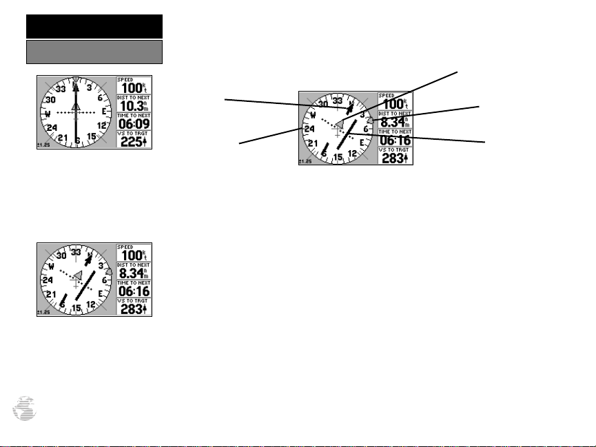
HSI Page
The other primary navigation screens are the HSI and Highway pages, with the
HSI Page appearing first in the sequence of main pages.
To view the HSI Page, press PAGE.
TO/FROM Indicator
From the HSI Page, you can
increase/decrease the
simulated speed using the
UP/DOWN keys on the
rocker keypad.
To move off course in simulator mode, use the LEFT/
RIGHT rocker keypad keys.
22
Pointer
(Desired Course)
Compass Card
(Track)
Bug Indicator
D-bar and
CDI Scale
The HSI Page provides graphic steering guidance to your destination waypoint.
The page features a graphic HSI (horizontal situation indicator), including a rotating
‘compass card’ that shows your course over ground (track) while you’re moving, a
course pointer and CDI (course deviation indicator) which indicate the desired
course to your destination. The compass card, pointer arrow and CDI work independently to show—at a glance—the direction you’re travelling, the desired course
and whether or not you are off course.
At the center of the CDI is a ‘D-bar’, or course deviation bar. If you move off
course, the D-bar will indicate how far off course you are and in what direction. The
scale for the CDI is indicated at the bottom of the page. The scale represents the
distance from the center of the CDI to full left or right limits.
As you approach the waypoint, a TO/FROM indicator will signal waypoint crossing. The current speed, distance to the next waypoint, time to the next waypoint and
vertical speed to target are all displayed to the right of the graphic HSI. To see how all
this works on our simulated trip, let’s head off course and watch the displays change.
To move off course/on course in simulator mode, use the LEFT/RIGHT
keys on the rocker keypad.
Page 31

SIMULATOR TOUR
The GPS III Pilot’s Highway Page provides a graphic highway display that shows
your movement relative to the desired course. The line down the middle of the highway represents your desired course. As you navigate toward your destination, the highway will actually move, indicating the direction you’re off course. To stay on course,
simply steer toward the center of the highway. As you approach the waypoint, the
highway will end at the final destination. When the waypoint marker is at the bottom
center of the highway display, you’ve arrived at your destination.
Track Compass
Highway
Display
The distance to the next waypoint, time to the next waypoint and current speed
are displayed to the right of the highway display. A track compass also shows your
current track directly above the highway display, making it easy to see at a glance
which way you’re headed.
The pointer arrow at the bottom of the page indicates the direction to the
destination waypoint (bearing) relative to the direction you are moving (track). If the
pointer points straight ahead, you’re heading directly to the waypoint. If not, turn in
the direction of the pointer and the pointer will swing around, pointing straight ahead
as you begin moving toward the destination waypoint. Let’s try changing the course
again and see how the highway display changes.
To move off course/on course in simulator mode, use the LEFT/RIGHT
keys on the rocker keypad.
Current Speed
Pointer
(Bearing to
Destination)
Highway Page
If you move off course, the
highway moves to indicate the
direction you’re off course. To
return to the course, steer
toward the highway centerline.
As you approach your destination, the highway will end
at the destination waypoint.
23
Page 32

SIMULATOR TOUR
Marking Present Position
Press and hold the ENTER/
MARK key to save your
present position as a user
waypoint.
Imagine you’ve just departed. Your home airport is thirty minutes behind you.
You fly over a nice fishing lake or golf course you’ve never noticed before and decide
you would like to return to this place in your car. How would you mark this spot?
The GPS III Pilot’s ENTER/MARK key provides a simple way to mark your present
position and save it as a waypoint.
To mark your present position:
1. Press and hold the ENTER/MARK key. The mark position page will appear, with a
default three-digit name for the new waypoint in the upper-left portion of the page.
2. Let’s call this location ‘SIMUL8’. To change the name, highlight the waypoint name
field (at the top of the page) and press ENTER. Use the rocker keypad to enter the
new name — UP/DOWN to change the first character (‘S’), RIGHT to move to the next
character (‘I’), and repeat. Press and hold UP or DOWN to cycle through the characters more quickly. Once the new name is spelled out, press ENTER to accept it.
Waypoint Name
Field
Position
Coordinates
Waypoint
Symbol Field
User waypoints can be
assigned a custom symbol,
making it easy to identify the
waypoint on the Map Page.
24
3. Now let’s use a special symbol to identify the location. Highlight the waypoint symbol
field (immediately right of the name field) and press ENTER. Use UP/DOWN on the
rocker keypad to select the ‘Information’ icon (‘?’) and press ENTER.
4. To save the new waypoint, highlight ‘DONE’ with the rocker keypad and press ENTER.
Page 33

Suppose another thirty minutes into your flight you experience an emergency and
need to find a place to land. Or, you just want to stop for a break at a nearby airport
or top off the tanks. A list of the nine nearest airports within 200 miles of your present
position is just a keystroke away! Instantly, you can select an airport from the list and
designate it as your destination waypoint. Or, you can review all the available Jeppesen
data for that particular airport. Let’s take a look at the closest airports in your area.
To view the nine nearest airports:
1. Press and hold the GOTO/NRST key. The Nearest Page will appear.
2. Using the LEFT/RIGHT keys on the rocker keypad, select the ‘Airports’ tab to see up to
nine nearest airports, along with bearing and distance to each.
To GOTO a nearest airport:
1. Using the UP/DOWN keys on the rocker keypad, highlight the desired airport.
2. Press GOTO/NRST, followed by ENTER, to designate the airport as your destination.
To view the Jeppesen data for a nearest airport:
1. Using the UP/DOWN keys on the rocker keypad, highlight the desired airport.
2. Press ENTER to view the waypoint information pages.
3. Use the LEFT/RIGHT keys on the rocker keypad to select the ‘Airport’, ‘Runway’ or
‘Comm’ information pages.
SIMULATOR TOUR
Nearest Waypoints
Press and hold the GOTO/
NRST key to view the Nearest
Page. Select the ‘Airports’ file
tab to see the nine nearest
airports.
To GOTO a nearest airport,
highlight the desired airport
using the rocker keypad, press
GOTO/NRST, then ENTER.
25
Page 34

SIMULATOR TOUR
Airspace War nings
When you are projected to
enter an airspace, the first
alert is typically ‘Airspace
Ahead Less Than 10 minutes’.
To view additional information about the airspace alert,
press and hold the GOTO/
NRST key and select the
‘Airspaces’ file tab.
26
As you continue along your route, you may pass in close proximity to, or enter,
an airspace. Whenever you are within 2 nm, projected to enter, or inside an airspace,
the GPS III Pilot will notify you with a message and supply detailed information
about each airspace you are being alerted to. Look closely at the map display. If you
see an airspace ahead of your present course, you may be alerted with a message as
you approach it.
?
NOTE: The airspace alert occurs when your current altitude places you within
the floor and ceiling limits of the airspace. If you are several hundred feet, or more,
below or above these limits, the GPS III Pilot will not bother you with an alert, but
the airspace boundary will still appear on the Map Page.
To view detailed information about an airspace alert:
1. Press and hold the GOTO/NRST key.
2. Use the LEFT/RIGHT keys on the rocker keypad to highlight the ‘Airspaces’ tab.
3. Use the UP/DOWN keys to highlight the desired airspace (if more than one is listed)
and press ENTER.
That’s it! You’ve covered the basics and you’re ready to venture off on your own.
Operating the GPS III Pilot is just as simple as you’ve seen here in the Simulator Tour,
but in real applications you won’t need to change speed and track with the rocker
keypad. That’s all done automatically utilizing information from the GPS satellites as
you move about.
Before ending the tour, try a few experiments of your own, such as going to the
‘SIMUL8’ waypoint or experimenting with the vertical navigation features (see page
43). Use the Reference section of this manual for more ideas.
To end the Simulator Tour, turn the GPS III Pilot off with the power key.
#
Page 35

REFERENCE
The GPS III Pilot’s Satellite Status Page provides a visual reference of various
receiver functions, including current satellite coverage, receiver status, battery level
and position accuracy. As the receiver locks onto satellites, a signal strength bar will
appear for each satellite in view, with the appropriate satellite number (01-32) underneath each bar. The progress of satellite acquisition is shown in three stages:
• No signal strength bars— the receiver is looking for the satellites indicated.
• Hollow signal strength bars— the receiver has found the satellite(s) and is
collecting data.
• Solid signal strength bars— the receiver has collected the necessary data and
the satellite(s) is ready for use.
Each satellite has a 30-second data transmission that must be collected (hollow bar
status) before that satellite may be used for navigation (solid bar status). Once a fix has
been calculated, the GPS III Pilot will then update your position, track, and speed by
selecting and using the best satellites in view. You can also access the GPS III Pilot’s
contrast feature from this page.
To adjust the screen contrast:
1. Press LEFT or RIGHT on the rocker keypad to adjust the level of contrast, and press
ENTER to save the new contrast setting.
Satellite Status Page
The Satellite Status Page
shows where the satellites are
and how strong the signal is
from each one. A solid signal
bar means the satellite is
ready to use.
Sky View and Signal Strength Bars
The sky view and signal strength bars give you an indication of what satellites are
visible to the receiver, whether or not they are being used to calculate a position fix,
and the signal quality. The satellite sky view shows a bird’s-eye view of the position of
each available satellite relative to the unit’s last known position. The outer circle represents the horizon (north up); the inner circle 45º above the horizon; and the center
point directly overhead.
Use the LEFT/RIGHT keys on
the rocker keypad to adjust
the screen contrast. Press
ENTER to save the setting.
27
Page 36

REFERENCE
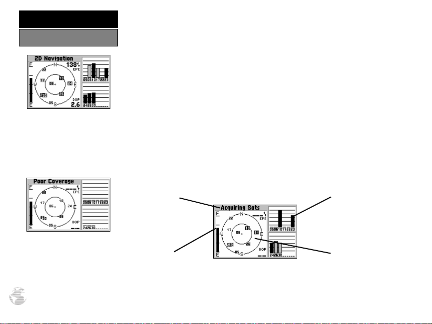
Satellite Status Page
‘2D Navigation’ means the
GPS III Pilot has determined a
horizontal position (latitude/
longitude), but is unable to
determine altitude. Additional
satellites may be needed.
‘3D Navigation’ means the
GPS IIIPilot has determined
a horizontal and vertical position (latitude, longitude and
altitude). The receiver is
ready for navigation.
28
You can use the sky view to help determine if any satellites are being blocked,
and whether you have a current position fix (indicated by ‘2D Navigation’ or ‘3D
Navigation’ in the status field). You can also set the sky view to a ‘Track Up’ configuration, causing the top of the sky view to align along your current track heading.
When the receiver is looking for a particular satellite, the corresponding signal
strength bar will be blank and the sky view indicator will not be highlighted. Once
the receiver has found the satellite, a hollow signal strength bar will appear, indicating that the satellite has been found and the receiver is collecting data from it. The
satellite number on the sky view will appear highlighted. As soon as the GPS III Pilot
has collected the necessary data to calculate a fix, the status field will indicate a 2D
or 3D status. (For ‘2D’, you may need to enter your altitude. See page 32.)
Receiver Status
Receiver status is indicated at the top left of the page. The status will be shown
as one of the following conditions:
Searching— the GPS III Pilot is looking for any available satellites in view.
AutoLocate— the GPS III Pilot is initializing and collecting new almanac data. This
process can take up to 5 minutes, depending on the satellites currently in view.
Acquiring— the receiver is collecting data from available satellites, but has not
collected enough data to calculate a position fix.
2D Navigation— at least three satellites with good geometry have been locked
onto and a 2-dimensional position fix (latitude and longitude) is being calculat-
ed. ‘2D Diff’ will appear when you are receiving DGPS corrections in 2D mode.
3D Navigation— at least four satellites with good geometry have been locked
onto, and your position is now being calculated in latitude, longitude and alti-
tude. ‘3D Diff’ will appear when you are receiving DGPS corrections in 3D mode.
Page 37

Poor GPS Coverage— the receiver isn’t tracking enough satellites for a 2D or 3D
fix due to bad satellite geometry.
Not Usable— the receiver is unusable, possibly due to incorrect initialization or
abnormal satellite conditions. Turn the unit off and back on to reset, and reinitialize the receiver if necessary.
Simulating Nav— the receiver is in simulator mode.
‘Need to Select Initialization’ Prompt
If no satellites are received for several minutes (or an insufficient number of satellites are received to determine a position fix) a message will appear, prompting you to
initialize the receiver (see page 5). This allows you to specify a starting location from
which to search for satellites, or to enable the AutoLocate feature, and is useful if you
have traveled over 500 miles with the receiver off. (This message will automatically
appear when you first use your GPS III Pilot. The prompt may also appear during normal use if the antenna is shaded or the unit is used indoors.)
Battery Level Indicator
The Satellite Status Page also features a battery level indicator, located to the left of
the sky view, which displays the strength of the unit’s batteries. The battery indicator
will not appear if the receiver is operating on external power.
?
NOTE: The battery level indicator is calibrated for alkaline batteries. NiCad and
lithium batteries will display the battery level differently due to voltage differences. To
display battery level accurately select the appropriate type, as described on page 79.
The GPS III Pilot features an internal 10-year lithium battery that will maintain the
unit’s memory when the receiver is not running off batteries or external power.
#
REFERENCE
Satellite Status Page
‘Poor GPS Coverage’ means
the receiver isn’t tracking
enough satellites for a position
fix. Check for obstructions,
including metal objects, trees,
buildings, etc.
This message appears if a
position fix cannot be determined after several minutes.
After acknowledging the message, select ‘Use Map’ or
‘AutoLocate’.
29
Page 38

REFERENCE
Satellite Status Page
When screen backlighting is
on, a bulb icon will appear in
the lower-left corner of the
Satellite Status Page.
The Satellite Status Page
Options allow you to enable
the built-in simulator, change
the sky view orientation or
initialize the receiver.
30
EPE and DOP
The Satellite Status Page also indicates the accuracy of the position fix, using
Estimated Position Error (EPE) and Dilution of Precision (DOP) figures. DOP measures satellite geometry quality (i.e., number of satellites received and where they are
relative to each other) on a scale from one to ten. The lowest numbers are the best
accuracy and the highest numbers are the worst. EPE uses DOP and other factors to
calculate a horizontal position error, in feet or meters.
Screen Backlighting
The GPS III Pilot’s backlight feature illuminates the display and keypad for a
user-defined interval (the default is 15 seconds) after the last key press. There are
three levels of backlighting. When backlighting is on, a bulb icon will appear at the
bottom left of the sky view. To adjust the duration of the screen backlighting, refer
to the operation setup section (see p. 79).
To turn the screen backlighting on:
1. Cycle through the three levels of backlight by repeatedly pressing the red power key.
To turn the screen backlighting off:
1. Press the red power key. Whenever the GPSIII Pilot’s backlighting is off, the bulb
icon disappears from the Satellite Status Page.
Satellite Status Page Options
Many features of the GPS III Pilot are menu driven. Each of the main pages has
an options menu, allowing you to custom tailor the corresponding page to your preferences and/or select special features which specifically relate to that page.
To display the Satellite Status Page Options, press MENU (with the
Satellite Status Page displayed).
Page 39

REFERENCE
The following Satellite Status Page options are available:
Start Simulator— allows you to activate the GPS III Pilot’s built-in simulator mode.
If ‘Start Simulator’ is selected, ‘Stop Simulator’ will appear as an option instead.
To activate (deactivate) simulator mode:
1. Highlight ‘Start Simulator’ (or ‘Stop Simulator’) and press ENTER.
2. Press ENTER again to confirm.
Track Up— changes the sky view display from ‘North Up’ orientation to align to
current direction of travel (track). If ‘Track Up’ is selected, ‘North Up’ will appear
as an option instead.
To change the sky view orientation:
1. Highlight ‘Track Up’ (or ‘North Up’) and press ENTER.
AutoLocate— forces the GPS III Pilot to search for any available satellite(s) to
determine its position. This option may be used if you’ve relocated a long distance
(>500 mi.) from the last location the GPS III Pilot was used.
To select AutoLocate, highlight ‘AutoLocate’ and press ENTER.
Initialize Position— allows you to designate your approximate position in order
to speed up satellite acquisition. This option may be used in lieu of ‘AutoLocate’
(above) and typically provides a position fix quicker.
To initialize your starting position:
1. Highlight ‘Initialize Position’ and press ENTER.
2. Designate your approximate position on the map using the rocker keypad and press
ENTER. (You may wish to use the IN/OUT zoom keys to adjust the level of detail
displayed, as you determine your approximate position.)
Satellite Status Page Options
‘AutoLocate’ forces the receiver to search for all satellites
(twelve at a time) until
enough satellites are found to
determine a position.
‘Initialize Position’ is used to
designate your approximate
position directly on the map
display. The receiver uses this
information to determine
which satellites should be in
view.
31
Page 40

REFERENCE
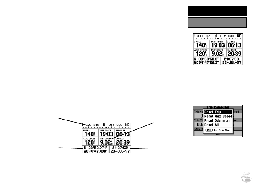
Position Page
The Position Page shows you
where you are, what direction
you’re heading and how fast
you’re going.
With 2D coverage, you will
need to enter your approximate altitude. Without an
approximate altitude, your
position error can be substantial.
32
The second page in the GPS III Pilot’s main page sequence is the Position Page.
This page shows you where you are, what direction you’re heading, and how fast
you’re going, and it’s most useful when you are traveling without an active destination waypoint. The graphic heading display at the top of the page indicates the direction you’re heading, or track, only while you’re moving.
Directly below this display are the speed, average speed, trip timer, trip odometer and sunrise/sunset fields (default). The sunrise/sunset times indicated are for
your present position. These times, and the current time display in the lower righthand corner, can be displayed in local time or UTC (zulu) time. The lower left-hand
corner of the page shows your current latitude and longitude in degrees and minutes
(default). Units of measure and the position readout are selectable from the Main
Menu, as outlined on page 77. Average speed, max speed, trip odometer and timers
can each be reset from the Main Menu, as described on page 75.
2D Altitude Entry
When the GPS III Pilot is acquiring satellites or navigating in the 2D mode, the
last known altitude will be used to compute your position. If the altitude shown is
off by several hundred feet, you can manually enter your altitude for greater accuracy. In cases where the GPS III Pilot has only 2D coverage, entering your approximate
altitude will enable the receiver to more accurately determine a position fix.
To enter an altitude:
1. Press PAGE(or QUIT) until the Satellite Status Page appears, then press MENU to
view the available options.
2. Highlight ‘Set 2D Altitude’ and press ENTER.
3. Enter your approximate altitude using the rocker keypad, and press ENTER.
Page 41

Many features of the GPS III Pilot are menu driven. Each of the main pages has an
options menu, allowing you to custom tailor the corresponding page to your preferences and/or select special features which specifically relate to that page.
To display the Position Page Options, press MENU (with the Position
Page displayed).
The following options are available:
Average Position— allows you to average position samples over time and save
the averaged result as a waypoint. Averaging reduces the effects of selective availability on position error and results in a more accurate position reading.
To average position samples and save the result as a waypoint:
1. Highlight ‘Average Position’ and press ENTER. The Average Position Page will appear.
Observe the ‘Estimated Accuracy’ and ‘Measurement Time’ fields.
2. When the ‘Estimated Accuracy’ and/or ‘Measurement Time’ figures reach the desired
value(s), highlight ‘Save’ and press ENTER. (To cancel the averaging function, highlight
‘Discard’ and press ENTER.)
3. The Waypoint Definition Page appears with a three-digit number assigned as a name
for the new waypoint. To save the waypoint with this name, highlight ‘Done’ and
press ENTER. Or,
4. To change the waypoint name, highlight the waypoint name field and press ENTER.
Use the rocker keypad to enter a new name for this waypoint and press ENTER when
finished. Highlight ‘Done’ and press ENTER to save the waypoint.
REFERENCE
Position Page Options
The Position Page Options
allow you to average position
samples and save the result as
a waypoint, change data fields
or restore factory defaults.
When averaging positions to
create a waypoint, observe the
‘Estimated Accuracy’ and
‘Measurement Time’ figures.
When they reach the desired
value(s), highlight ‘Save’ and
press ENTER.
33
Page 42

REFERENCE
Position Page Options
‘Change Fields’ allows you to
custom tailor the information
that appears on the Position
Page. Select the desired data
type from the list.
‘Restore Defaults’ will override any data field changes
you’ve made to the Position
Page, reverting back to the
factory default settings.
34
Change fields— allows you to choose the data displayed on the six user-selectable
data fields. Available data types are: Altitude, Average (Avg) Speed, Battery (Bat)
Timer, Max Speed, Odometer, Speed, Sunrise (at present position), Sunset (at pre
sent position), Track, Trip Odometer, Trip Timer, User Timer and Voltage. See
page 98 for descriptions of navigation terms.
To change a data field:
1. Highlight ‘Change Fields’ and press ENTER.
2. Highlight the data field you wish to change (using the rocker keypad) and press ENTER.
3. Select the type of data you want to appear on this field and press ENTER.
Restore Defaults— resets all data fields to the factory default settings.
To restore the factory default settings, highlight ‘Restore Defaults’ and
press ENTER.
Page 43

REFERENCE
The GPS III Pilot features a powerful real-time moving map that can do much more
than just plot your course and route. The Map Page also displays a digital chart, including airspace boundaries, airports, navaids, lakes, rivers, coastlines and highways. An onscreen cursor lets you pan ahead to other map areas, determine the distance and bearing to any map position, and perform various waypoint and route functions. The GPS III
Pilot also features dedicated zoom keys for instant zooming (see p. 2). The map portion
of the page displays your present position using an aircraft icon, with your track and/or
route displayed as small points on the screen (an electronic bread crumb trail, if you
will). You may select which features are shown via the Map Page Options (see pp. 37).
The data window beside (or above when display is vertical) the map displays the
time and distance to next waypoint, plus your current speed (all defaults). A bearing
pointer lets you know if you’re heading toward your destination. If the pointer points
straight ahead, you’re heading directly to it. If the pointer points any direction other
than up, turn toward the arrow until it points up—then continue in that direction.
Each data field may be configured to display any one of twenty-eight data options.
Zooming and Panning
There are three main functions you can perform from the Map Page: zooming,
panning, and pointing. The map display has 23 scales (from 120 feet to 500 miles, or
30 meters to 800 km) which are selected by pressing the IN and OUT zoom keys. The
current map scale is indicated in the bottom left corner of the map display.
To change the map scale:
1. Press zoom IN to see a smaller area with more detail.
2. Press zoom OUT to see a larger area with less detail.
Map Page
The Map Page displays a digital chart, including airspace
boundaries, airports, navaids,
rivers, lakes and highways.
Zoom IN to see more detail
for a smaller area. Zoom
OUT to see a larger area.
35
Page 44

REFERENCE
Map Page
Use the rocker keypad to pan
away from your present position.
Place the pointer over an airport
or navaid and press ENTER to
see more information.
By placing the panning pointer
over an on-screen waypoint
and pressing GOTO/ NRST,
you won’t have to manually
enter the identifier for the
waypoint.
36
Another function on the Map Page is the pan function, which allows you to
move the map with the keypad in order to view areas beyond the current map.
To activate the pan function:
1. Use the rocker keypad to move the map in any direction, including diagonally.
As you begin to pan on the map, a pointer appears. This map pointer will serve
as a target marker for the map. When the pointer is placed on an object, the name
of that object will be highlighted. (If the name wasn’t originally displayed it will
appear when the pointer is placed on the object.) This feature applies to airports,
navaids, user-created waypoints, roads, lakes, rivers—pretty much everything displayed except route lines and track log data.
When a waypoint name is highlighted, you can review information about the
waypoint, list waypoint options, or execute a GOTO right from the Map Page.
To select an on-screen airport or navaid with the panning pointer:
1. Use the rocker keypad to highlight the desired item.
2. To view additional database information about the selected item, press ENTER/MARK.
3. To exit the information pages, press QUIT.
To GOTO a highlighted waypoint:
1. With the waypoint highlighted, press GOTO/NRST, followed by ENTER.
The GOTO function can be used anywhere on the map. If nothing currently
exists at the map pointer position, a new waypoint (called ‘MAP’) will be created at
the pointer’s location before the GOTO is initiated.
To cancel the pan function and re-center the map on your position:
1. Press the QUIT key.
Page 45

Many features of the GPS III Pilot are menu driven. Each of the main pages has an
options menu, allowing you to custom tailor the corresponding page to your preferences and/or select special features which specifically relate to that page.
To display the Map Page Options, press MENU (with the Map Page displayed).
The following options are available:
Data Fields Off— allows you to select between a full-screen map display or the
default map display with data window. If the data fields are off, ‘Data Fields On’
will appear as an option instead.
To turn the data fields off (or on), highlight ‘Data Fields Off’ (or ‘Data
Fields On’) and press ENTER.
Change fields— allows you to choose the data displayed on four user-selectable
data fields. There are twenty-eight available data types, including Average (AVG)
Speed, Bearing, Distance, ETA to Destination (DEST), Speed, Time to Destination,
Track and a Trip Odometer. See page 98 for descriptions of navigation terms.
To change a data field:
1. Highlight ‘Change Fields’ and press ENTER.
2. Highlight the data field you wish to change and press ENTER.
3. Select the type of data you want to appear on this field and press ENTER.
Measure Dist— allows you to measure the bearing and distance between any two
points on the map display.
To measure bearing and distance between two points:
1. Highlight ‘Measure Dist’ and press ENTER. An on-screen pointer will appear on the
map display at your present position.
REFERENCE
Map Page Options
A full-screen map, without the
data fields, is available by
selecting the ‘Data Fields Off’
option.
When using the ‘Measure
Dist’ option, an arrow
appears with an ‘Enter
Reference’ prompt. Point to
the initial reference point and
press ENTER.
37
Page 46

REFERENCE
Map Page Options
‘Setup Map’ allows you to
change map orientation,
background map detail, onscreen Jeppesen data, text
size, etc.
The map settings are organized by a series of ‘file tabs’.
Use the rocker keypad to
select the desired tab, and to
select the desired setting(s).
38
2. Move the pointer to the desired reference point (the point you want to measure from)
and press ENTER.
3. Move the pointer to the point you want to measure to. The bearing and distance from
the reference point will be displayed at the bottom left of the data window.
Restore Defaults— resets all data fields to the factory default settings.
To restore the factory default settings, highlight ‘Restore Defaults’ and
press ENTER.
Setup Map— allows you to configure the map display to your preferences,
including map orientation, land data enable/disable, Jeppesen data enable/disable, automatic zoom, airspace boundaries, and text size. The map setup option
uses a ‘file tab’ feature, making it easier to organize the various settings and easier for you to use. The following table lists the file tabs and available settings:
Map Orientation, AutoZoom, Land Data, Aviation Data
Line Track Log, Active Route Lines, Lat/Long Grid Lines
Wpt User Waypoints, Waypoint Text, Active Route Wpts
Apt Large/Medium/Small Airports and Text
Nav VORs, NDBs, Intersections and Text
Ctrl Controlled Airspace: Class B/C/D
SUA Special-Use Airspace: Restricted, MOA, Other
City Large/Medium/Small Cities and Text
Road Freeway, Nat’l Highway, Local Highway, Local Road
Other States/Prov, Rivers/Lakes, Metro Areas, Railroads
NOTE: Large airports are those with a runway longer than 8000’. Medium airports are those with
a runway longer than 5000’ or with a control tower. Large cities are those with approximate populations greater than 100,000 and medium cities are those with approximate populations over 5,000.
Page 47

To change a map setup feature:
1. Highlight ‘Map Setup’ and press ENTER.
2. To change map orientation, select the ‘Map’ tab (if not already selected) and press
ENTER. Highlight the ‘Orientation’ field and press ENTER. Select ‘North Up’ to fix the
top of the map display to a north heading. Select ‘Track Up’ to adjust the top of the
map display to your current track heading. Select ‘DTK Up’ to fix the top of the map
display to your desired course. Press ENTER to accept the selected option.
3. To enable/disable automatic zoom, select the ‘Map’ tab (if not already selected), highlight the ‘Auto Zoom’ field and press ENTER. Select ‘On’ or ‘Off to enable or disable
automatic zoom. Press ENTER to accept the selected option. The automatic zoom feature will automatically adjust the map scale from 80 nm through each lower scale, stopping at 800 ft as you approach your destination waypoint.
4. To enable/disable all land data or aviation data, select the ‘Map’ tab (if not already
selected) and press ENTER. Highlight the appropriate field and press ENTER. Select
‘On’ or ‘Off’ to enable or disable all land data. Press ENTER to accept selected option.
5. For airports, navaids, active route waypoints, user waypoints, state/provincial boundaries, rivers/lakes and cities: select the appropriate tab (per the chart on page 38) and
press ENTER. Highlight the zoom field for the desired feature and press ENTER. Select
the maximum scale at which the feature should appear on screen, or ‘Off’ to never display, and press ENTER. Highlight the text field for the desired feature and press ENTER.
Select the text size for the desired feature, or ‘None’ to disable text, and press ENTER.
6. For airspace boundaries, highways, roads, railroad lines, metro areas, track log data,
active route lines and lat/long grid: select the appropriate tab (per the chart on page
38) and press ENTER. Highlight the zoom field for the desired feature and press ENTER.
Select the maximum scale at which the feature should appear on screen, or select ‘Off’
to never display the feature. Press ENTER to accept the settings.
Select the ‘North Up’ option
to keep the top of the map
display fixed on North. ‘Track
Up’ will cause the map to
rotate so the top of the map is
the direction you’re heading.
The ‘Zoom’ setting allows you
to define the maximum scale
at which the feature will
appear. Once selected, that
feature will appear at the
selected scale and all lower
scale settings.
REFERENCE
Map Page Options
39
Page 48

REFERENCE
HSI Page
This example shows the aircraft heading parallel to the
desired course, with the aircraft right of course more
than 0.5 nm.
When off course beyond the
limits of the CDI scale, the
D-bar will appear in gray
and stay at the edge of the
scale (until your off course
error is less than the limits of
40
the scale).
Desired Course
Pointer
TO/FROM
Indicator
CDI Scale Setting
Bug Indicator
Compass Card
(Track)
D-bar
(part of CDI)
The primary navigation page, the HSI Page, also provides graphic steering guidance to your destination. The graphic HSI depicts the desired course to the destination
waypoint (or the next waypoint in a route), current track, off course error and a
TO/FROM indication. The rotating compass card indicates your current track, at the
top of the page. The desired course pointer and CDI indicate the desired course and
whether or not you’re on the desired course. A bug indicator provides course to steer
(CTS) information, guiding you back to the desired course should you stray off course.
The CDI is indicated by a course deviation scale (across the center of the HSI) and
a moving D-bar (course deviation bar). If you move off course, the D-bar will indicate
how far off course you are, based upon its placement along the course deviation scale.
To get back on course and center the D-bar, simply steer toward the D-bar. The CDI
scale setting is adjustable for 0.25, 1.25 or 5.0 (nautical mile/ statute mile/kilometer).
The default setting is 1.25, which represents the distance from the center of the CDI
to full left or right limits.
To change the CDI scale, use the IN/OUT zoom keys.
As you reach your destination, a TO/FROM indicator at the center of the HSI will
indicate waypoint passage. Along the right-hand side of the page (top, when display
is vertical) are four user-selectable data fields that display current speed, distance and
time to next waypoint, and vertical speed to target (a vertical navigation function,
described on page 43). These data fields may be configured to display different data.
Page 49

Many features of the GPS III Pilot are menu driven. Each of the main pages has an
options menu, allowing you to custom tailor the corresponding page to your preferences and/or select special features which specifically relate to that page.
To display the HSI Page Options, press MENU (with the HSI Page
displayed).
The following options are available:
Set OBS and Hold— allows you to manually define the course to your destination waypoint. Once selected, the GPS III Pilot will use the OBS course setting for
steering guidance with the CDI and desired course pointer.
?
NOTE: When using the GPS III Pilot’s route features, ‘Set OBS and Hold’ will pre-
vent the unit from automatically sequencing to the next route waypoint. To maintain
the OBS course and retain automatic sequencing, you must also select the ‘Release
Hold’ option, described on the following page.
To manually set a course to the destination waypoint:
1. Highlight ‘Set OBS and Hold’ and press ENTER. An OBS data field will appear on the
HSI display.
2. Select the desired OBS course using the LEFT/RIGHT keys on the rocker keypad and
press ENTER. The D-bar on the CDI and the desired course pointer will now provide
steering guidance to the selected course.
To cancel the OBS course and reset a direct course to the waypoint, press
GOTO and ENTER (or re-activate the route).
#
The ‘Set OBS and Hold’
option allows you to specify
an inbound heading to a
destination waypoint.
Use the rocker keypad to
select the desired OBS
heading. Note the heading at
bottom center of HSI display
(155° in this example).
REFERENCE
HSI Page Options
41
Page 50

REFERENCE
HSI Page Options
‘Big Numbers’ provides a
smaller compass-type display,
with a pointer indicating the
bearing to your destination.
The ‘Change Fields’ option
allows you to select from a list
of available data types. Four
different items may be displayed on the HSI Page’s user-
selectable data fields.
42
Release Hold— cancels the ‘hold’ feature enabled when the ‘Set OBS and Hold’
option was selected. This option returns the GPS III Pilot to automatic sequencing of waypoints along the active route. However, if an OBS course has been
selected, that course setting will be retained until cancelled (as described on page
41) or until waypoint passage.
To release a waypoint hold and return to automatic sequencing of route
waypoints, highlight ‘Release Hold’ and press ENTER.
Big Numbers— allows you to select a different page layout, with a smaller
compass-type display and two user-selectable, large-character data fields. If
‘Big Numbers’ is selected, ‘HSI’ will appear as an option instead.
To toggle between HSI and Big Numbers page formats, highlight ‘Big
Numbers’ (or ‘HSI’) and press ENTER.
Change Fields— allows you to choose the data displayed on four user-selectable
data fields. There are twenty-nine available data types, including Average (AVG)
Speed, Bearing, Distance, ETA at Destination (DEST), Speed, T ime to Destination
(DEST), Track, and a Trip Odometer. See page 98 for descriptions of data terms.
To change a data field:
1. Highlight ‘Change Fields’ and press ENTER.
2. Highlight the data field you wish to change and press ENTER.
3. Select the type of data you want to appear on this field and press ENTER.
Restore Defaults— resets all data fields to the factory default settings.
To restore the factory default settings, highlight ‘Restore Defaults’ and
press ENTER.
Page 51

Capture VNA V Profile— is used to center/re-center the VNAV indicator (see illus-
tration to the right) on the HSI display. To utilize this feature, a GOTO or route must
HSI Page Options
be in use and a valid vertical navigation profile must be entered on the vertical navigation setup page (see the following page and page 75).
Cancel Capture— is used to return the VNAV indicator to the settings originally
entered on the vertical navigation setup page (see the following page and page 75).
Vertical Navigation
VNAV PROFILE
DISTANCE TO PROFILE
GLIDE RATIO TO TARGET
TARGET ALTITUDE
DISTANCE TO TARGET
AIRPORT
When using the vertical
navigation features, a VNAV
indicator (moving horizontal
bar) will guide you as you
descend to the target altitude.
The GPS III Pilot’s vertical navigation feature allows you to create a threedimensional profile which guides you from your present position and altitude to a
final (target) altitude at a specified location. Once the profile is defined, message alerts
and additional data on the HSI Page will keep you informed of your progress.
?
NOTE: To use the vertical navigation feature, your speed must be greater than 35
#
The Main Menu’s ‘Vertical Nav’
option allows you to define the
target altitude and where it
should occur. The default settings are intended to guide you
to pattern altitudes.
knots and you must be navigating to a GOTO destination or using a route.
REFERENCE
43
Page 52

REFERENCE
Vertical Navigation
Your target altitude can be
defined as height ‘Above Wpt’
or ‘MSL’. ‘Above Wpt’ only
applies to airports. Use ‘MSL’
for all other waypoint types.
When using a route, vertical
navigation can apply to any
waypoint along the route by
selecting it as the ‘VNAV
Waypoint’.
44
To create a vertical navigation profile:
1. Select the Main Menu by pressing MENU twice.
2. Select ‘Vertical Nav’ using the rocker keypad and press ENTER.
3. With the ‘Target Altitude’ field highlighted, press ENTER. Enter the desired target altitude and press ENTER.
4. With the altitude reference field (immediately to the right of ‘Target Altitude’) highlighted, press ENTER. Select ‘Above Wpt’ or ‘MSL’ (as desired) and press ENTER.
‘Above Wpt’ will use the altitude of a destination airport as stored in the internal
Jeppesen database. ‘MSL’ lets you set a specific target altitude for any waypoint
category: airport, VOR, NDB, intersection or user waypoint.
5. With the waypoint distance ‘By’ field highlighted, press ENTER. Enter an offset distance from the destination waypoint where the target altitude should be reached. If
the target altitude occurs at the destination waypoint, enter a distance of zero. Press
ENTER when finished.
6. With the offset direction field (immediately to the right of ‘By’) highlighted, press
ENTER. Select ‘Before’ or ‘After’ and press ENTER. This setting designates whether
the offset distance defines a point before you reach the destination waypoint or after
you reach the destination waypoint.
7. When using a route, the ‘VNav Waypoint’ field allows you to specify which route
waypoint will be used for the vertical navigation profile. By default, the GPS IIIPilot
will select the last waypoint in the route. To select a different waypoint, highlight the
‘VNAV Waypoint’ field, press ENTER, select the desired waypoint and press ENTER.
8. The default profile utilizes a 400 foot-per-minute descent rate. To change the rate,
highlight the ‘Profile’ field, press ENTER, enter a new rate and press ENTER again.
9. To enable/disable all vertical navigation messages, highlight the ‘Message’ field and
press ENTER. Select ‘On’ or ‘Off’ (as desired) and press ENTER.
Page 53

REFERENCE
With the profile set, the HSIPage will guide you thr ough the maneuver . Data fields
on the HSI Page can be configured to indicate the time to beginning of maneuver, glide
ratio and vertical speed to target. A VNAV indicator on the HSI display will guide you
along the proper descent angle. Expect the following to occur when using the vertical
navigation feature:
• As you approach the initial descent point, the time to vertical navigation
(‘Time to VNV’) field indicates the time to reach the initial descent point.
• At one minute prior to the initial descent point, a message ‘Approaching
VNAV Profile’ occurs. The time to vertical navigation (‘Time to VNV’) will
sequence from indicating time to initial descent point to indicating time to
reach target altitude. Finally, the descent angle will lock to prevent changes
in speed from altering the profile.
• At 500 feet above the target altitude, an ‘Approaching Target Altitude’ message is provided. The time to vertical navigation (‘Time to VNV’) figure will
go blank and the VNAV indicator will disappear from the HSI Page.
!
WARNING: GPS accuracy may be degraded by the U.S. Department of Defense-
imposed Selective Availability (SA) pr ogram. W ith ‘SA’ on, GPS altitude may be in error
by several hundred feet. Errors of this magnitude may result in fluctuations in the
VNAV indicator on the HSIPage. The GPS III Pilot is a VFR navigation tool and should
not be used to perform instrument approaches.
#
Vertical Navigation
Within one minute of the
initial descent point, an
‘Approaching VNAV Profile’
message will appear.
Once you are within 500 feet
of the target altitude, the
‘Approaching Target Altitude’
message will appear and the
VNAV indicator will be
removed from the HSI
display.
45
Page 54

REFERENCE
Highway Page
Your course is represented by
the highway center line. Keep
the center line in the middle
of the display to stay on
course.
When using a route, the
Highway Page will guide you
to each waypoint along the
route.
46
Whenever a destination waypoint(s) has been selected, the GPS III Pilot’s
Highway Page will guide you to your destination with digital readouts and a highway display. Along the right side of the page (top, when display is vertical) are four
user-selectable data fields that display current speed, distance and time to next waypoint, and a bearing pointer (defaults). The bearing pointer always points to the destination waypoint (or the next waypoint when using a route) relative to the direction
you are moving (track). If the bearing pointer points straight ahead, you are heading
directly to your destination. If the bearing pointer points any direction other than
up, turn toward the arrow until it points up—then continue in that direction.
The graphic heading compass at the top of the page indicates the direction you are
moving (track). Directly below the heading compass, the highway display provides
visual guidance to the destination waypoint and keeps you on your intended course
line. Your course is represented by the center line down the middle of the graphic
highway. As you head toward your destination, the highway perspective will move to
indicate your progress to the waypoint and which direction you should steer to stay on
course. If you are navigating a route, the highway display will show each route waypoint in sequence, with the route course indicated by a black highway. Nearby airports
not in the route will also be displayed. Five available scale settings allow you to zoom
in or out on the highway display for a smaller or larger view. The current scale setting,
ranging from 1X to 16X, appears on the lower right corner of the highway display.
To zoom in or out on the highway display:
1. Press the IN zoom key to decrease the scale and show a smaller view area.
2. Press the OUT zoom key to increase the scale and show a larger view area.
Page 55

Many features of the GPS III Pilot are menu driven. Each of the main pages has an
options menu, allowing you to custom tailor the corresponding page to your preferences and/or select special features which specifically relate to that page.
To display the Highway Page Options, press MENU (with the Highway
Page displayed).
The following options are available:
Sign Posts Off— removes the waypoint markers from the highway display. If ‘Sign
Posts Off’ is selected, ‘Sign Posts On’ will appear as an option instead.
To remove (or display) waypoint markers on the highway, highlight ‘Sign
Posts Off ’ (or ‘Sign Posts On’) and press ENTER.
Change Fields— allows you to choose the data displayed on four user-selectable
data fields. There are twenty-seven available data types, including Average (AVG)
Speed, Bearing, Distance, ETA at Destination (DEST), Speed, Time to Destination
(DEST), Track, a Trip Odometer and a bearing pointer. See page 98 for descrip-
tions of navigation terms.
To change a data field:
1. Highlight ‘Change Fields’ and press ENTER.
2. Highlight the data field you wish to change and press ENTER.
3. Select the type of data you want to appear on this field and press ENTER.
Restore Defaults— resets all data fields to the factory default settings.
To restore the factory default settings, highlight ‘Restore Defaults’ and
press ENTER.
REFERENCE
Highway Page Options
The Highway Page Options
let you configure the Highway
Page to your preferences.
‘Change Fields’ allows you to
choose the type of data to display on four user-selectable
data fields. Select the desired
type from the ‘Change Fields’
list.
47
Page 56

REFERENCE
Waypoint Categories
The Main Menu’s ‘Waypoints’
option allows you to view
database information for airports, runways, comm frequencies, VORs, NDBs, etc.
Select the desired waypoint
category by selecting the
corresponding ‘file tab’ at the
top of the page.
48
Your GPS III Pilot uses a built-in Jeppesen database to provide position and
facility information for thousands of airports, VORs, NDBs and intersections. Each
facility in the database is stored as a waypoint, with its own latitude/longitude, identifier (up to six letters and/or numbers) and other pertinent information. Waypoint
information is available from the ‘Waypoints’ selection under the Main Menu.
Waypoint information is divided into categories (each represented by a ‘file tab’),
with different types of information available for each. The following table lists the file
tabs and information available under each tab:
Airport Identifier, city/state, name, position, elevation, fuel
Runway Length, width, orientation, surface, lighting, diagram
Comm Frequencies for: ATIS, pre-taxi, clearance, ground,
tower, unicom, multicom, approach, departure,
arrival, class B, class C, TMA, CTA, TRSA
VOR Identifier, city/state, facility name, position, freq.,
indication of co-located DME or TACAN
NDB Identifier, city/state, facility name, position, freq.
Int Intersection name, region/country, nearest VOR
User Wpt Name, position, user comments, reference waypoint
User List Name, symbol, total number of user waypts created
To view waypoint information:
1. Press MENU twice to display the main menu.
2. Highlight ‘Waypoints’ using the rocker keypad and press ENTER. One of the waypoint
information pages listed above will be displayed.
3. A series of tabs across the top of the page will indicate the other available pages.
Select the desired page using the rocker keypad.
Page 57

REFERENCE
Waypoint Category
‘File Tabs’
Waypoint
Waypoint
Identifier Field
To select the desired waypoint, by identifier:
1. Highlight the waypoint identifier field using the rocker keypad and press ENTER.
2. Use the rocker keypad to enter the desired identifier—UP/DOWN to change each
character and RIGHT to move to the next character.
3. As the identifier is entered, the GPS IIIPilot will scroll through the database, displaying
any waypoints with the same identifier letters you have entered to that point. When
the desired waypoint is displayed, press ENTER.
?
NOTE: The GPS III Pilot uses International Civil Aviation Organization (ICAO)
identifiers to designate airports. In the United States, the prefix letter for airports is ‘K’.
This applies to airport identifiers that are letters only. For example, ‘LAX’ becomes
‘KLAX’ and ‘JFK’ becomes ‘KJFK’. Airport identifiers that use numbers, such as ‘H34’
or ‘7M5’, do not use the ‘K’ prefix.
Some waypoints in the database may have the same identifier. When you have
entered a waypoint name that is not unique, a Duplicate Waypoint Page appears,
prompting you to select the desired waypoint. A list showing each duplicate by waypoint category and region/country makes it easy to identify the correct one.
To select the desired waypoint from a list of duplicates, highlight the
desired waypoint and press ENTER.
#
Symbol Field
Waypoint Infor mation Pages
Waypoints are selected by
identifier (or name). Enter the
desired identifier in the waypoint identifier field, using the
rocker keypad.
If more than one waypoint
uses the same identifier, the
Duplicate Waypoint Page
allows you to choose the
correct one.
49
Page 58

REFERENCE
Waypoint Infor mation Pages
Airports, VORs and NDBs
can also be selected by the
facility’s name or the city
where the facility is located.
The Airport Information Page
includes airport position coordinates, field elevation and
available fuels. This page will
also indicate if the facility is
public use or military.
50
The ‘Airport’, ‘VOR’ and ‘NDB’ information pages also allow you to retrieve the
desired waypoint by entering the facility name or the city name.
To select the desired waypoint, by facility or city name:
1. Use the rocker keypad to highlight the facility name or city name field. Press ENTER.
2. Use the rocker keypad to enter the desired name—UP/DOWN to change each
character and RIGHT to move to the next character.
3. As the name is entered, the GPS IIIPilot will scroll through the database, displaying
any waypoints with the same letters you have entered to that point. In some instances
there may be more than one waypoint with the desired name. (This often occurs when
searching by city name.) To view all waypoints with the desired name, continue
spelling the name with the rocker keypad. Once the name appears on-screen,
continue to press UP/DOWN on the rocker keypad to view all entries for that name.
4. When the desired waypoint is displayed, press ENTER.
Airport Information Page
The Airport Information Page displays the identifier, facility name, city, position,
elevation and available fuels for the selected airport. Position and elevation information will be in the format specified on the Setup pages (see page 77). Available fuel
can be any of the following types:
• AV — AVGAS: 80-87 octane, 100LL, 100-130 octane
• JET — Jet A, Jet A-1, Jet A+
• MO — MOGAS: 87 octane unleaded
Page 59

REFERENCE
Runway Information Page
The Runway Information Page displays the identifier, designations, length, width,
surface type and lighting information for the selected airport. This page also provides
a graphic diagram of the runways and a map of the surrounding area. The surface type
information can be any one of: hard, turf, sealed, gravel, dirt, soft, unknown, or water .
The lighting information will indicate one of five lighting schemes: part time, full time,
pilot controlled (with frequency), no lighting or unknown.
If the selected airport has more than one runway, additional runway data can be
viewed by selecting another runway from the runway designation field.
To view additional runway data:
1. Highlight the runway designation field and press ENTER. A list of the available runways
will appear.
2. Select the desired runway using the rocker keypad and press ENTER.
Communication Information Page
The Communication Information Page displays the identifier and radio frequencies for the selected airport, along with any usage restrictions which may apply to a
given frequency. When a frequency type is followed by an ‘*’, that frequency will have
usage restrictions, typically based upon sector and/or altitude.
To view usage restrictions for a communication frequency:
1. Highlight the desired frequency (one with a type that’s followed by ‘*’) and press
ENTER. An information page will appear with additional data about the frequency.
2. Press QUIT to return to the Communication Information Page.
Waypoint Infor mation Pages
The Runway Information
Page allows you to view the
runways and the surrounding
area. Select the runway designation field to view data for
additional runways.
The Airport Communication
Information Page shows the
radio frequencies for the
selected airport. Any frequencies with restrictions are
denoted by an asterisk (‘*’)
after the frequency type.
51
Page 60

REFERENCE
Waypoint Infor mation Pages
The VOR Information Page
provides complete information
about the selected VOR,
including facility name, city,
frequency and designation for
co-located DME or TACAN.
Both the NDB and VOR
Information Pages provide
‘WX’ indications if the selected facility broadcasts weather
information.
52
VOR Information Page
The VOR Information Page displays the identifier, facility name, city name,
region/country, position and frequency for the selected VOR. The facility type (terminal, low altitude or high altitude) is also indicated. If DME or TACAN equipment
is co-located at the site, it will be indicated next to the transmitting frequency.
Likewise, if the facility broadcasts weather information, ‘WX’ will appear next to the
transmitting frequency. Position information will be in the format specified on the
Setup pages (see page 86).
NDB Information Page
The NDB Information Page displays the identifier, facility name, city name,
region/country, position and frequency for the selected NDB. If the facility broadcasts
weather information, it will be indicated by a ‘WX’ appearing next to the transmitting
frequency.
Intersection Information Page
The Intersection Information Page displays the identifier, position, region and
country for the selected intersection. The page also shows the bearing and distance to
the nearest VOR facility.
?
NOTE: The VOR displayed is simply the nearest facility and may not be the
facility used to define the intersection.
#
Page 61

In addition to being used to define a GOTO destination, the GPS III Pilot’s
GOTO/NRST key can also be used to view detailed information on the nine nearest
airports, VORs, NDBs, intersections and user waypoints within 200 miles of your present position. Information regarding the five nearest FSS (flight service station) and
center (ARTCC) points of communication, along with associated frequency(s) is available from the Nearest Page, as well. When an airspace alert is provided, the Nearest
Page will even provide additional detail about the airspace. Nearest information is
selected by choosing the appropriate ‘file tab’, based upon the desired information. The
following table lists the file tabs and information available under each tab:
Airports nine nearest with identifier, bearing to and distance
VORs nine nearest with identifier, bearing to and distance
NDBs nine nearest with identifier, bearing to and distance
Ints nine nearest with identifier, bearing to and distance
User Wpts nine nearest with name, bearing to and distance
ARTCC five nearest with bearing to, distance and frequency(s)
FSS five nearest with bearing to, distance, freq(s) and VOR
(for duplex operations)
Airspaces up to three (depending on number of alerts provided)
with type, controlling agency, frequency(s) and floor/
ceiling altitude limits
To view the Nearest Page:
1. Press and hold the GOTO/NRST key.
2. Select the desired information by highlighting the appropriate tab from the chart above.
REFERENCE
Nearest Airports, etc.
The Nearest Page organizes the
nearest airports, navaids, FSS,
center and airspace information by ‘file tab’ headings.
Select the appropriate tab for
the desired information.
Nearest airspace information
is available on the Nearest
Page, once an airspace alert
has been provided.
53
Page 62

REFERENCE
Nearest Airports, etc.
To view the database information for a nearby airspace,
highlight the airspace on the
Nearest Page and press
ENTER.
To immediately set a GOTO
course for a nearest airport,
highlight the desired airport
on the Nearest Page, press
GOTO/NRST and then
ENTER.
54
As mentioned earlier, additional information is stored in the GPSIII Pilot’s
Jeppesen database. This information may be retrieved using the ‘W aypoints’ option on
the Main Menu, but it is also available from the Nearest Page.
To view additional information for a nearest airport, VOR, NDB, intersection, user waypoint or airspace:
1. Highlight the desired item (from the Nearest Page) using the rocker keypad.
2. Press ENTER to view the database information for the selected item.
3. Press QUIT to return to the Nearest Page.
You can easily set a GOTO course dir ectly to a nearest waypoint. In an emer gency,
a few simple keystrokes can guide you to the closest point to set down. (See page 61
for more detail about the GPS III Pilot’s GOTO features.)
To GOTO a nearest waypoint, highlight the desired waypoint from the
Nearest Page, press GOTO/NRST and ENTER.
Airspace information also includes the frequency(s) of the controlling agency.
To view controlling agency frequency(s) for a nearby airspace:
1. With the information page displayed for the desired airspace, highlight the
‘Frequencies’ field and press ENTER.
The Nearest Page displays one FSS or ARTCC at a time. Information for up to five
remote communication outlets is available.
To view additional nearest FSS or ARTCC points of communication:
1. Highlight the ‘Station’ field and press ENTER.
2. Select the desired listing, numbered 1 through 5, and press ENTER.
Page 63

REFERENCE
In addition to the built-in database, the GPS III Pilot also stores up to 500 userdefined waypoints, with a selectable symbol and comment available for each waypoint.
User-defined waypoints can be created using four methods:
Mark Present Position— your present position can be captured and saved as a
user waypoint using the ENTER/MARK key (press & hold).
On Map— a new user waypoint position can be created directly on the map
display using the panning pointer and ENTER/MARK key (press momentarily).
Text Entry— user waypoints can be created by entering position coordinates
manually (from a chart, etc.) or by referencing bearing and distance from a
previously stored waypoint (or present position).
Average Position— position samples can be averaged over time and the result
saved as a user waypoint. Averaging reduces the effects of selective availability and
improves the accuracy of the position reading. (See page 33 for more info.)
Marking Present Position
The GPS III Pilot’s “mark” feature lets you quickly capture your present position in
order to create a new user waypoint. You must be locked onto satellites, with a valid
position fix, to mark your present position.
To mark your present position:
1. Press and hold the ENTER/MARK key. The New Waypoint Page is automatically
displayed.
2. To change the waypoint name (a three-digit number is automatically assigned),
highlight the waypoint name field and press ENTER. Use the rocker keypad to enter
the new waypoint name and press ENTER when finished.
3. To save the waypoint in memory, highlight ‘Done’ and press ENTER.
Creating User Waypoints
The ENTER/MARK key allows
you to mark your current position as a user waypoint. You
can give this waypoint any
name you choose.
You can also choose from a
list of symbols used to identify
the user waypoint on the map
display.
55
Page 64

REFERENCE
Creating User Waypoints
User waypoints can be created
directly from the Map Page,
by placing the panning pointer
on the desired position and
pressing ENTER.
User waypoints can also be
created by entering the
position coordinates for the
waypoint.
56
Marking User Waypoints on the Map Page
User waypoints can also be quickly created from the Map Page, which allows you
to “point and shoot” at any map position to create a new waypoint.
To create a new user waypoint on the map:
1. Press the PAGEkey repeatedly to select the Map Page.
2. Use the rocker keypad to move the pointer to the desired map position. You may
also need to use the IN and OUT zoom keys, in conjunction with the rocker keypad, to
speed up this process.
3. Press ENTER (momentarily) to capture the pointer’s position and display the New
Waypoint Page.
4. To change the waypoint name (a three-digit number is automatically assigned),
highlight the waypoint name field and press ENTER. Use the rocker keypad to enter
the new waypoint name and press ENTER when finished.
5. To save the waypoint in memory, highlight ‘Done’ and press ENTER.
Creating User Waypoints by Text Entry
User waypoints may be created by manually entering the position coordinates or
by entering the bearing and distance from an existing waypoint (or present position).
To create a new user waypoint by manually entering its coordinates, or
by bearing/distance from another position:
1. Press the MENU key twice to select the Main Menu.
2. Highlight ‘Waypoints’ and press ENTER.
3. Press MENU to display the Waypoint Options.
4. Highlight ‘New Waypoint’ and press ENTER. The Waypoint Definition Page appears.
Page 65

5. To enter a name for the new waypoint, highlight the waypoint name field and press
ENTER. Use the rocker keypad to enter the waypoint name and press ENTER when
finished.
6. To enter position coordinates for the new waypoint, highlight the waypoint coordinates
field and press ENTER. Use the rocker keypad to enter the position coordinates and
press ENTER when finished. (For lat/lon coordinates, enter both the latitude and
longitude information before pressing ENTER.) Or,
7. To create the new waypoint by referencing another position, highlight the reference
waypoint name field and press ENTER. Use the rocker keypad to enter the name of
the reference waypoint and press ENTER. (If the reference waypoint name field is
left blank, your present position will be used as the reference position.) Use the same
procedure to enter the bearing (BRG) and distance (DST) from the reference waypoint to the new waypoint. (Remember to press ENTER once each data item is
selected with the rocker keypad.)
8. To save the new waypoint in memory, highlight ‘Done’ and press ENTER.
Waypoint Options
The Waypoint Options wer e displayed using the first three steps above.In addition
to ‘New Waypoint’, ther e are additional options which vary depending on whether you
are viewing Jeppesen database waypoints or user-defined waypoints:
Show Map— allows you to view the map area around the selected waypoint.
While viewing the map display, you can also use the IN and OUT zoom keys to
see additional detail.
Edit Waypoint (‘User Wpt’ tab only)— allows you to modify name, symbol, com-
ment or position information for the selected waypoint.
Delete Waypoint (‘User Wpt’ and ‘User List’ tabs only)— allows you to delete the
selected user waypoint from memory.
REFERENCE
Creating User Waypoints
Select the ‘Show Map’ option
to display the map area
around a selected waypoint.
Once ‘Show Map’ is selected,
use the panning pointer
and/or the IN/OUT zoom
keys to view the desired area
and detail.
57
Page 66

REFERENCE
Editing User Waypoints
User waypoints can be deleted individually, by common
symbol or all at once. Select
the desired ‘Delete’ option and
press ENTER.
To rename a user waypoint,
enter the new name directly
over the old name and press
ENTER.
58
Delete by Symbol (‘User List’ tab only)— allows you to select a user waypoint
symbol and all waypoints with this corresponding symbol will be deleted from
memory.
Delete All (‘User List’ tab only)— deletes all user waypoints currently stored in
memory.
To delete a user waypoint (or waypoints):
1. Select the desired delete option from the list above and press ENTER.
2. If ‘Delete by Symbol’ is selected, select the desired symbol and press ENTER.
Editing User Waypoints
Once you have created and stored a user waypoint, it may be modified, renamed
or deleted at any time through the Waypoint Edit Page. The Waypoint Edit Page for
any stored user waypoint can be retrieved by selecting the desired waypoint on the
map display, or from the waypoint information pages (‘User Wpt’ or ‘User List’ tabs).
To access the Waypoint Edit Page for a user waypoint:
1. Press the rocker keypad to highlight the desired user waypoint on the map display
and press ENTER. Or,
2. Highlight ‘Waypoints’ from the Main Menu and press ENTER. Select the desired file
tab. If ‘User Wpt’ is selected, press MENU, select ‘Edit Waypoint’ and press ENTER. If
‘User List’ is selected, highlight the desired waypoint and press ENTER.
From the Waypoint Edit Page, highlight the appropriate field to rename a way-
point, change its symbol, edit the comment or edit the position.
To rename the user waypoint:
1. Highlight the waypoint name field and press ENTER.
2. Use the rocker keypad to enter the new waypoint name and press ENTER.
3. If finished, highlight ‘Done’ and press ENTER.
Page 67

To change the user waypoint’s symbol:
1. Highlight the waypoint symbol field and press ENTER.
2. Use the rocker keypad to select the desired symbol and press ENTER. The selected
symbol will be used to denote the waypoint position on the map display.
When a waypoint is created, the time and date of creation is automatically added
as a waypoint comment. You can edit this information or create an entirely new
comment, as needed.
To edit the user waypoint comment:
1. Highlight the waypoint comment field and press ENTER.
2. Use the rocker keypad to enter the desired comment and press ENTER.
To edit the user waypoint position:
1. Highlight the waypoint coordinates field to change the position coordinates, or
highlight the reference waypoint name, bearing or distance fields to change the
reference waypoint information. Press ENTER to begin editing.
2. Use the rocker keypad to enter the new information. Press ENTER to accept the new
information.
A user waypoint’s position may also be edited, graphically, using the map display.
To move a waypoint’s position on the map display:
1. From the Waypoint Edit Page, press MENU to display the Waypoint Edit Options.
2. Use the rocker keypad to select ‘Show Map’ and press ENTER.
3. Press MENU to display an options window. Select ‘Move Wpt’ and press ENTER.
4. Use the rocker keypad to select the new location for the waypoint and press ENTER.
REFERENCE
Editing User Waypoints
The default waypoint comment is the time and date the
waypoint was created. You
can enter your own comment
using the rocker keypad.
Edit a user waypoint’s
position by entering the new
position coordinates directly
over the old position.
59
Page 68

REFERENCE
Waypoint Options
‘Show Map’ allows you to
view the area around the user
waypoint’s position.
‘Display Options’ lets you
determine what user waypoint information will appear
on the map display.
60
The Waypoint Edit Page featur es additional options, besides the ‘Show Map’ option
described in the previous steps. Waypoint Edit Options allow you to delete user waypoints, define how a user waypoint will appear on the map display or average the waypoint position to improve accuracy.
To display the Waypoint Edit Options, press MENU (with the Waypoint
Edit Page displayed).
The following options are available:
Show Map— allows you to view the area surrounding the selected waypoint’s
position. While viewing the map display, you can also use the IN and OUT zoom
keys to see additional detail.
Delete Waypoint— allows you to remove the selected user waypoint from memory.
To delete a waypoint:
1. Highlight ‘Delete Waypoint’ and press ENTER. A confirmation screen is displayed.
2. ENTER to delete (or QUIT to cancel).
Display Options— lets you select how the highlighted user waypoint will appear
on the map display. Options are provided to show symbol & name, symbol &
comment, or symbol only.
To change the display options for a user waypoint:
1. Highlight ‘Display Options’ and press ENTER.
2. Highlight the desired option and press ENTER.
Average Position— allows you to average position samples over time to improve
the accuracy of the position reading and save the result as a user waypoint. (See
page 33 for more information on averaging.)
Page 69

REFERENCE
The GPS III Pilot can navigate to a destination using any of three different methods:
GOTO— lets you select a waypoint as your destination and quickly plot a direct
course from present position to that waypoint.
TracBack— allows you to retrace your path using the track log automatically
stored in the receiver’s memory. This eliminates the need to store waypoints along
the way. (See page 64 for more information about TracBack.)
Routes— allows you to manually create a sequence of intermediate waypoints
which lead you to your final destination. The GPS III Pilot will store up to 20
reversible routes, with up to 30 waypoints in each route.
GOTO Navigation
The easiest way to select your destination is by using the GOTO key. The GOTO
key can be used by itself, after highlighting a waypoint name on a list, or after
designating a position on the map display.
To GOTO a waypoint:
1. Press GOTO/NRST. The GOTO page shows a series of file tabs for ‘Recent’ waypoints,
‘User’ waypoints or ‘Spell n Find’.
2. To GOTO a recently used waypoint, select the ‘Recent’ tab, highlight the desired waypoint and press ENTER.
3. To GOTO a user waypoint, select the ‘User’ tab, highlight the desired waypoint
and press ENTER.
4. To enter the identifier of the destination waypoint, select the ‘Spell n Find’ tab and
highlight the waypoint identifier (name) field. Press ENTER and use the rocker keypad
to enter the identifier of the desired waypoint—UP/DOWN to change each character
and RIGHT to move to the next character. Press ENTER to confirm the selection.
Navigation/GOTO
To GOTO a waypoint, press
GOTO/NRST and highlight
the waypoint identifier field at
the top of the page.
Press ENTER and use the
rocker keypad to enter the
identifier of the destination
waypoint. Press ENTER to
begin navigation.
61
Page 70

REFERENCE
GOTO
By highlighting a waypoint
identifier on a list and pressing GOTO/NRST, you won’t
have to manually enter the
identifier for the waypoint.
A GOTO can also be initiated
from the map display by placing the panning pointer on the
desired target waypoint.
62
To designate a GOTO waypoint from a list of waypoints:
1. Highlight the desired waypoint on the list and press GOTO/NRST. A confirmation page
shows the selected destination waypoint.
2. Press ENTER to confirm the selected waypoint and begin navigating.
To GOTO an existing waypoint on the map display:
1. Use the rocker keypad to place the crosshair on the desired target waypoint.
2. Press GOTO/NRST, followed by ENTER, to begin navigating.
To GOTO any position on the map display:
1. Use the rocker keypad to place the crosshair on any position you wish to navigate to.
2. Press GOTO/NRST to create a waypoint, called ‘MAP’, at the crosshair position. Each
time you perform this step, it will overwrite any previously created ‘MAP’ waypoint.
3. Press ENTER to being navigating.
To select a GOTO waypoint by facility name or city (applicable to airports,
VORs and NDBs only):
1.
Press GOTO/NRST and select the ‘Spell n Find’ tab, as described on the previous page.
2. Highlight the facility name or city name field, as desired, and press ENTER.
3. Use the rocker keypad to enter the facility name/city. As you enter the first few characters, the GPS IIIPilot’s Spell n Find feature will scroll through the database, displaying any waypoints which match the letters you have entered. When searching by city
name, there may be mulitiple waypoints for the same city. Continue scrolling with the
UP/DOWN portion of the rocker keypad to scroll through these entries.
4. When the desired waypoint appears, press ENTER.
Page 71

GOTO Options are also provided to initiate a TracBack route or to cancel the
current GOTO destination.
To display the GOTO Options, press MENU (immediately after pressing
GOTO/NRST).
The following options are available:
TracBack— allows you to retrace your path using the track log automatically
stored in the receiver’s memory. This eliminates the need to store waypoints
along the way. (See page 64 for more information about TracBack.)
Cancel GOTO— cancels the current GOTO destination and resumes navigation
of any previously selected route. If no route is currently in use; bearing, distance,
etc. will remain blank until a destination waypoint is defined.
To cancel the current GOTO destination, highlight ‘Cancel GOTO’ and
press ENTER.
REFERENCE
GOTO Options
‘TracBack’ allows you to
retrace your path based upon
an automatic track log
recording.
To cancel a current GOTO
destination, select ‘Cancel
GOTO’ from the GOTO
Options.
63
Page 72

REFERENCE
TracBack
Clear the old track log before
you depart. This defines the
starting point for a TracBack
route.
‘TracBack’ can also be initiated from the Main Menu’s
‘Track Log’ option.
64
The TracBack navigation feature allows you to retrace your path using the track
log automatically stored in the receiver’s memory. This eliminates the need to manually store waypoints along the way. A track log is an electronic breadcrumb trail showing the path you have travelled. Your GPSIII Pilot can be set to automatically record
track log points anytime the receiver is on and locked onto satellites (see page 74).
TracBack routes are created by reducing your track log into a route of up to 30
waypoints and activating the new route in reverse order along those waypoints. Once
activated, a TracBack route will lead you back to the oldest track log point stored in
memory, so it’s a good idea to clear the existing track log at the beginning of your current trip (e.g., at your home airport) before you get started.
To clear the track log and define the starting point for a TracBack route:
1. Press MENU twice to display the Main Menu.
2. Highlight ‘Track Log’ and press ENTER.
3. Highlight ‘Clear Log’ and press ENTER.
4. Press ENTER to delete the track log data (or press QUIT to cancel).
To create and activate a TracBack route:
1. Enable track log recording and leave the GPS III Pilot on to automatically record track
log positions while under way. Refer to page 74 for information on track log settings.
2. Press MENU twice to display the Main Menu.
3. Highlight ‘Track Log’ and press ENTER.
4. Highlight ‘TracBack’ and press ENTER to create/activate the TracBack route. (A
message box will appear while the unit analyzes the data and creates the route.)
Page 73

REFERENCE
Once a TracBack has been activated, the GPS III Pilot will take the track log currently stored in memory and divide it into route segments, called ‘legs’. Up to 30 track
log waypoints (labeled ‘T###’, e.g. ‘T001’) will be created to mark the most significant
features of the track log in order to duplicate your path as closely as possible. To gain
the most benefit from the TracBack feature, keep the following tips in mind:
• Always clear the track log at the point you want to return to (your home, your
home airport, etc.)
• The ‘Record Mode’ on the Track Log Setup Page must be set to ‘Wrap’ or ‘Fill’.
• There must be at least two track log points stored in memory to create a
TracBack route.
• If there is not enough available memory to add more waypoints and create a
TracBack route, you will be alerted with a ‘waypoint memory full’ message. The
receiver will use the available waypoints to create a route with an emphasis on
the track log closest to the destination. Also, existing track log waypoints that are
not contained in any route will be erased to free more memory. The GPS III Pilot
will create the new waypoints using the first available three-digit number.
• If the Track Log Setup Page’s ‘interval’ field is set to ‘T ime’, the r oute may not follow your exact path. (Keep the ‘interval’ field set to ‘Resolution’ for best results.)
• If the receiver is turned off or satellite coverage is lost during your trip, TracBack
will draw a straight line between any point where coverage was lost and where
it resumed.
• If there are frequent changes in direction and distance in your track log, 30 waypoints may not accurately depict your exact path. The receiver will then assign
the 30 waypoints to the most significant points of your track log, and simplify
segments with fewer changes in direction.
TracBack Tips
A TracBack route contains a
series of waypoints labeled
‘T###’ that approximate your
previous route of travel.
‘Wrap’ will overwrite the old
track log data in memory,
once all memory has been
used.
65
Page 74

REFERENCE
Routes
To display the Route List,
showing all routes stored in
memory, select ‘Routes’ from
the Main Menu.
Select ‘New Route’ from the
Route Options and enter the
identifiers for the route waypoints in the sequence you
wish to follow them.
66
Route navigation allows you to manually create a sequence of intermediate waypoints which lead you to your final destination. The GPS III Pilot will store up to 20
reversible routes, with up to 30 waypoints in each route. Routes can be created and
modified by text entry—using the rocker keypad to enter waypoint names. All of the
GPS III Pilot’s route functions are accessed through a ‘Routes’ option on the Main Menu.
To create a new route:
1. Press MENU twice to display the Main Menu.
2. Highlight ‘Routes’ and press ENTER. The Route List is displayed, showing all routes
stored in memory.
3. Press MENU to display the Route Options.
4. Highlight ‘New Route’ and press ENTER. The GPS III Pilot creates a route called
‘Empty-XX’. (The name changes as you add waypoints to the route, so make note of
the route name for future reference.)
5. Highlight the first waypoint name field and press ENTER to begin entering the name of
an existing waypoint in memory.
6. Use the rocker keypad to enter the name of the route waypoint and press ENTER.
7. Highlight the next waypoint name field, press ENTER and repeat step 6 until all route
waypoints have been added to the route.
Route List
The GPS III Pilot’s Route List displays all the routes currently stored in memory,
along with a descriptive name for each route. Once a route has been created, it can be
activated and used for navigation from the Route List. A route may be followed in the
same sequence as it was originally created, or you can invert the route and navigate
from the end waypoint back to the beginning waypoint.
Page 75

To activate a route:
1. Press MENU twice to display the Main Menu.
2. Highlight ‘Routes’ and press ENTER. The Route List is displayed, showing all routes
stored in memory.
3. Highlight the desired route and press MENU to display the Route Options.
4. Highlight ‘Activate’ to navigate the route in sequence, and press ENTER.
The Route List also allows you to enter your own 13-character name for any list-
ed route. By default the name includes the first and last waypoints in the route.
To enter a custom route name:
1. Follow steps 1 and 2 above to display the Route List.
2. Highlight the desired route and press ENTER to display the Route Edit Page.
3. Highlight the route name field (top line) and press ENTER to begin editing.
4. Use the rocker keypad to enter the desired name and press ENTER when finished.
When a route is highlighted on the Route List, additional functions are available
from the Route Options.
To display the Route Options, press MENU (with the Route List
displayed).
The following Route Options are available:
New Route— allows you to create a new route, as described on page 66.
Activate— allows you to navigate the route in the same sequence it was original-
ly created, as described above.
REFERENCE
Route List
Activating a route tells the
GPS IIIPilot you wish to use
this route for navigation
guidance.
Selecting a GOTO destination
along the current route will
take you directly to that waypoint, then continue with the
remainder of the route.
67
Page 76

REFERENCE
Route Options
‘Copy’ allows you to make a
duplicate of a route before
making editing changes.
‘Delete’ will remove the route
from memory, but not the
waypoints contained in the
route.
68
Invert— allows you to reverse the order of waypoints in the route.
Copy— allows you to copy the selected route to a new route. The copy function
can be used to save a TracBack route for future use. The copy function is also
useful for duplicating an existing route before making changes.
To copy a route:
1. Highlight ‘Copy’ and press ENTER.
2. The Route Plan Page will appear for the duplicate route and the name for the new
route will be first and last waypoints in the route. If this name is identical to the original route name (or any other saved route), then a number will be added to the end of
the name to create a unique name.
Delete Route— allows you to remove the selected route from memory. The
waypoints contained in the route will still appear in memory, but not as part of
the route.
To delete a route from memory:
1. Highlight ‘Delete Route’ and press ENTER. A confirmation page will appear.
2. Press ENTER to delete the route (or QUIT to cancel).
Delete All— allows you to remove all routes from memory. The waypoints contained in all stored routes will remain in memory, but not as part of any route.
To delete all routes from memory:
1. Highlight ‘Delete All’ and press ENTER. A confirmation page will appear.
2. Press ENTER to delete all routes (or QUIT to cancel).
Page 77

Once a route is added to memory, you can review and/or edit the route from the
Route Edit Page. The Route Edit Page shows the sequence of waypoints for the selected route and provides additional options to insert waypoints, remove waypoints or
perform trip/fuel planning functions.
To edit a route:
1. From the Route List, highlight the route you wish to edit and press ENTER. The Route
Edit Page appears for the selected route.
2. To change a route waypoint, highlight the waypoint you wish to change and press
ENTER. Use the rocker keypad to enter the new waypoint and press ENTER.
3. To review the information for a route waypoint, highlight the desired waypoint and
press MENU. A pop-up menu appears with additional options. Highlight ‘Review Wpt’
and press ENTER to display the Waypoint Definition Page for the selected waypoint.
4. To insert a waypoint in the route, highlight the waypoint that will immediately follow the
new route waypoint and press MENU. A pop-up menu appears with additional options.
Highlight ‘Insert Wpt’ and press ENTER to display a blank line for the new waypoint.
Enter the name of the new waypoint and press ENTER.
5. To delete a waypoint from the route, highlight the waypoint you wish to delete and
press MENU. Highlight ‘Remove Wpt’ on the pop-up menu and press ENTER.
To edit a route from the map display:
1. Follow step 1 above to select the Route Edit Page, press MENU and select ‘Show Map’.
2. To insert a new waypoint move the pointer to the route leg in which the new waypoint
will be placed. press ENTER, move the pointer to the new waypoint location and press
ENTER to insert the new waypoint.
3. To remove a waypoint, move the pointer to the waypoint, press MENU and select
‘Remove Wpt’.
REFERENCE
Route Editing
The Route Options allow for
easy editing of an existing
route.
To edit a route, highlight the
route waypoint which is
affected by the change. If
inserting a waypoint, highlight
the existing waypoint which
follows the new waypoint.
69
Page 78

REFERENCE
Route Editing
With a route displayed, use
the LEFT/RIGHT keys on the
rocker keypad to select the
trip planning features.
The Active Route Page shows
the route currently being used
for navigation guidance.
70
The Route Edit Page also displays trip planning information for each leg or the
entire route. Available information includes desired course, time to waypoint, distance
to waypoint, required fuel and sunrise/sunset times at the waypoint location.
To use the trip planning features:
1. To select the desired planning figure, highlight the desired route from the Route List
and press ENTER to display the Route Edit Page. One of ten available planning figures
appears to the right of each route waypoint. Use the LEFT/RIGHT keys on the rocker
keypad to select the desired item.
2. To enter planning information, Press MENU and select ‘Setup Plan’ from the options
list. Enter the figures for speed, fuel flow and departure date/time.
Active Route Page
The last page appearing in the main sequence (using the PAGE or QUIT keys) is
the Active Route Page. Whenever you have activated a route, GOTO or TracBack, the
Active Route Page will show each waypoint (by name) of the active route, along with
the desired course, distance to waypoint, time to each waypoint, fuel requirements or
sunrise/sunset times at each route waypoint. As you navigate the route, the information on the Active Route Page will automatically update to indicate the destination
waypoint and any remaining interim waypoints.
From the Active Route Page, you can change the name of the active route (see page
67), review information on a route waypoint (see page 48) or bypass route waypoints
and GOTO any waypoint in the route (see page 62). The user-selectable data field on
the right side of the page also keeps you informed of current conditions. There are ten
different data items available. See page 98 for descriptions of navigation terms.
To change the Active Route Page data, press the LEFT/RIGHT keys on the
rocker keypad.
Page 79

Many features of the GPS III Pilot are menu driven. Each of the main pages has an
options menu, allowing you to custom tailor the corresponding page to your preferences and/or select special features which specifically relate to that page.
To display the Active Route Page Options, press MENU (with the Active
Route Page displayed).
The following options are available:
Setup Plan— displays a trip planning screen, allowing you to plan and review
distance, fuel and time en route information for the selected route.
To use the trip planning features:
1. Highlight ‘Setup Plan’ and press ENTER. A setup screen is provided for planned speed,
fuel flow and departure time.
2. To enter a speed for your trip, highlight the speed field, press ENTER and use the
rocker keypad to select the desired speed. Press ENTER to confirm.
3. Enter an hourly fuel flow (if desired) in the fuel field, using the same steps above.
4. Enter the date and time of departure (the current date/time will be offered automatically), using the same steps above.
5. Press QUIT to return to the Active Route Page, and use the LEFT/RIGHT portion of the
rocker keypad to select the planning figures (to the immediate right of each listed route
waypoint’s identifier).
Re-evaluate— reactivates the current route and selects the route leg closest to
your current position as the active leg. The active leg defines the current ‘from’
and ‘to’ waypoints.
Deactivate— cancels navigation of the route you are currently using.
REFERENCE
Active Route Page Options
‘Setup Plan’ allows you to
define planned speed, fuel
flow and departure time in
order to review trip planning
figures.
‘Re-evaluate’ will reactivate
the current route and select
the closest leg. This feature is
handy if you stray well off
course and later wish to
return to the route.
71
Page 80

REFERENCE
Active Route Page Options
To reverse the sequence of
waypoints in the active route,
select the ‘Invert’ option.
To delete the active route from
memory, select the ‘Delete
Route’ option.
72
Invert— reactivates the current route in reverse order and navigates from the end
waypoint back to the beginning waypoint.
Insert Wpt— allows you to insert an additional waypoint into the route, directly
in front of the currently highlighted waypoint in the route. If no route waypoint is
highlighted, this option is not available. See page 69 for route editing info.
Remove Wpt— removes the currently highlighted waypoint from the route. If
no waypoint is highlighted, this option is not available. See page 69 for route
editing information.
Review Wpt— allows you to view the Waypoint Definition Page for the currently highlighted waypoint in the route. If no route waypoint is highlighted, this
option is not available. See page 48 for waypoint review information.
Delete Route— allows you to remove the current route from memory. The waypoints contained in the route will still appear in memory, but not as part of the
route. See page 68.
Page 81

The GPS III Pilot’s Main Menu provides access to the waypoint, route, track log,
trip planning and setup features of the receiver . The Main Menu can be accessed at any
time using the MENU key.
To display the Main Menu, press the MENU key twice.
The 7 menu options are divided into categories by function: waypoints/routes/
track log, trip computer, vertical navigation/E6B and system setups.
To select an option from the Main Menu, highlight the desired item and
press ENTER.
The following menu options are available:
Waypoints— allows you to review database information and create/edit/delete
user waypoints. See pages 48-52 and pages 55-59.
Routes— allows you to create, edit, activate or delete routes. See pages 66-70.
Track Log— lets you specify whether or not to record a track log (an electronic
‘breadcrumb trail’ recording of your path) and defines how it is recorded. This
submenu page also provides an indicator of the percentage of track memory used
and options to clear the track memory or start a TracBack route. See pages 64-65
for TracBack information.
REFERENCE
Main Menu
Press MENUtwice to display
the Main Menu.
Select the desired menu option
by highlighting it with the
rocker keypad and pressing
ENTER.
73
Page 82

REFERENCE
Main Menu
‘Fill’ will record track log data
until memory is full, then provide a ‘Track Memory Full’
message.
To utilize the TracBack feature, you should clear the
track log before leaving the
departure airport.
74
Track Log Settings
Record Mode lets you select one of three track recording options:
‘Off’ – No track log will be recorded.
?
NOTE: Selecting ‘Off’ will prevent you from using the TracBack feature.
‘Fill’ – A track log will be recorded until the track memory is full.
‘Wrap’ (default) – A track log will be continuously recorded by wrapping through
available memory and replacing the oldest track data with new data.
Interval defines the frequency with which the track plot is recorded. Three interval
settings are available:
‘Time’ – Records track log based on a user-defined time interval.
‘Resolution’ (default) – Records track log based upon a user-defined variance from
your course over ground. The resolution option is recommended for the most
efficient use of memory and TracBack performance. The distance value (entered in
the ‘Interval Value’ field) is the maximum left/right deviation allowed from the last
defined ground track before recording a new point.
‘Distance’ – Records track log based on a user-defined distance between points.
Interval Value defines the distance or time inter val used to record the track log.
Clear Log allows you to clear the track log data currently stored in memory.
To delete the track log data, highlight ‘Delete Track’ and press ENTER.
TracBack converts the track log data in memory into an inverted route and begins
navigation along the route. See pages 64-65.
#
Page 83

Trip Computer— provides readouts for average speed, maximum speed,
odometer, trip odometer and trip timer. These readouts can be reset from the Trip
Computer Options.
To reset a trip computer readout(s):
1. Press MENU (with the Trip Computer Page displayed). An options list is displayed.
2. To reset all trip computer readouts, highlight ‘Reset All’ and press ENTER.
3. To reset a single readout item, highlight the desired option and press ENTER.
?
NOTE: The ‘Reset Trip’ option resets trip odometer, trip timer and average speed readouts.
V ertical Nav— allows you to define a vertical navigation profile used to descend
(or climb) to a target altitude at a specified location. See pages 43-45.
E6B— provides calculation features for density altitude, true airspeed and winds
aloft. The winds aloft function will calculate wind direction, speed and the head/tail
wind component.
To calculate density altitude and true airspeed:
1. Select the ‘Density Altitude’ file tab using the rocker keypad.
2. Highlight the ‘Indicated Altitude’ field and press ENTER. Enter the altitude from your
altimeter and press ENTER.
3. Highlight the ‘Calibrated Airspeed’ field and press ENTER. Enter the airspeed from
your airspeed indicator and press ENTER.
4. Highlight the ‘Pressure’ field and press ENTER. Enter the current altimeter setting
(barometric pressure) and press ENTER.
#
REFERENCE
Main Menu
‘Trip Computer’ provides
readouts for the trip odometer,
trip timer, average speed and
maximum speed. Options are
provided to reset these figures.
Density altitude and true airspeed may be calculated by
entering values for indicated
altitude, calibrated airspeed,
barometric pressure and total
air temperature.
75
Page 84

REFERENCE
Main Menu / Setup
The ‘Winds’ option allows you
to calculate the current headwind or tailwind component.
The ‘Setup’ option uses file
tabs for quick selection/review
of unit settings.
76
5. Highlight the ‘Total Air Temperature’ (TAT) field and press ENTER. Enter the TAT and
press ENTER.
?
NOTE: TAT is the temperature of the air including the heating effect caused by speed.
The temperature reading on a standard outside air temperature gauge found on most
piston aircraft is TAT.
6. The ‘Density Altitude’ and ‘True Airspeed’ figures will appear at the bottom of the page.
To calculate winds aloft:
1. Select the ‘Winds’ file tab, using the rocker keypad.
2. Highlight the ‘Heading’ field and press ENTER. Enter the current aircraft heading and
press ENTER.
3. Highlight the ‘True Airspeed’ field and press ENTER. Enter the current true airspeed
and press ENTER. (If the true airspeed was previously determined on the ‘Density
Altitude’ page, the calculated figure will automatically appear here as the default.)
4. The ‘Head (Tail) Wind’, ‘Wind From’ and ‘Wind Speed’ figures will appear at the bottom
of the page.
Setup— provides a group of pages to perform various system setup functions,
including selection of position format, units of measure, setting various alarms, configuring the display and backlighting. Each available page is denoted by a ‘file tab’
which identifies the function of that page.
To select a Setup option, highlight the file tab for the desired function.
The information is automatically displayed when the file tab is highlighted.
#
Page 85

The file tab headings and setup functions for these pages are:
Simulator Enable/Disable; Settings for simulated track, speed
and altitude
System Backlight timeout, Battery type, Display Contrast and
Orientation
Units Units of measure settings for—Distance & Speed,
Heading, Altitude, Pressure and Temperature
Timers Count up/down User Timer, Battery Timer, and
usage timers for current day and since new
Time Formats for local 24 hour, local 12 hour (AM/PM) or
UTC; Difference setting from UTC to local time
Alarms Alarm Clock, Arrival Alarm, Off Course Alarm
Airspace Airspace alarms for: Class B, Class C, Class D,
Restricted Areas, MOAs, Other SUAs and Mode C
Veils; Altitude buffer above/below airspace limits
Nearest Runway surface type and Minimum Runway
Length for nearest airport search
Position Position Format (latitude/longitude, UTM/UPS,
Maidenhead, regional grids); Map Datum selection
Interface Format (NMEA, RTCM, GARMIN proprietary);
Mode setting for use with PC or a second unit
The following pages describe, in more detail, the available settings for each Setup
file tab item.
REFERENCE
Setup
To display the desired information, highlight the appropriate file tab.
Once the desired information
is selected, use the UP/
DOWN keys on the rocker
keypad to select the desired
item on the page.
77
Page 86

REFERENCE
Setup: Simulator
‘Simulator’ allows you to
enable/disable the built-in
simulator feature—and set
simulated speed, track and
altitude.
The ‘Track Control’ setting
allows the simulator to automatically “line up” on the correct bearing to a destination
waypoint.
78
Simulator Settings
Mode lets you turn the built-in simulator on or off.
To enable/disable the built-in simulator:
1. Highlight the ‘Mode’ field and press ENTER.
2. Select ‘Simulator Off’ or ‘Simulator On’ (as desired) and press ENTER.
Speed lets you select a simulated speed when the simulator is enabled.
Track Controlallows the built-in simulator to automatically align track heading to the
desired course (when using a GOTO or route), or it allows you to manually adjust the
track heading, as desired.
Track allows you to manually enter a track heading. This setting is only available when
Track Control is set to ‘User Track’.
Altitude allows you to specify a user-defined altitude for your simulated position.
To select a simulator setting:
1. For track control, highlight the ‘Track Control’ field and press ENTER. Select ‘AutoTrack’ or
‘User Track’ and press ENTER.
2. For simulated speed, user track, or altitude, highlight the desired field and press ENTER. Enter
the desired value using the rocker keypad and press ENTER when finished.
Page 87

System Settings
Backlight lets you keep the screen/keypad backlighting on continuously (‘always on’)
when selected, or enables the automatic shutoff to preserve battery life. Automatic shutoff
times from 15 seconds to 4 minutes (since last key press) are available.
To set the backlight timeout:
1. Highlight the ‘Backlight’ field and press ENTER.
2. To keep backlighting on continuously, select ‘Always On’ and press ENTER. Or,
3. To set a timeout duration, select the desired time period and press ENTER.
?
NOTE: Backlighting timeout is automatically disabled when using external power.
Battery is used to designate the type of batteries currently being used to power your GPS
III Pilot: Alkaline, Lithium or NiCad. This setting ensures accurate readings from the
battery gauge on the Satellite Status Page (see page 29).
Contrast lets you adjust the screen for optimum viewing in all lighting conditions. Screen
contrast is set using an on-screen bar scale. Contrast can also be set from the Satellite
Status Page, as described on page 27.
To set the screen contrast:
1. Highlight the ‘Contrast’ field and press ENTER.
2. Use the LEFT/RIGHT keys on the rocker keypad to select desired level and press ENTER.
Display allows you set the display orientation to horizontal (‘Landscape’) or vertical
(‘Portrait’).
NOTE: Display orientation can also be changed by pressing and holding the PAGE key.
#
?
#
REFERENCE
Setup: System
You can adjust the screen contrast from the Satellite Status
Page or from the ‘System’ settings.
Display orientation is
adjustable by pressing/holding
the PAGE key or from the
‘System’ settings.
79
Page 88

REFERENCE
Setup: Units
Select nautical, statute or
metric units of measure from
the ‘Units’ settings.
The ‘User Mag’ option allows
you to define the magnetic
variation for your area. ‘Auto
Mag Var’ is the preferred setting in most cases.
80
Units Settings
Distance & Speed lets you select the desired units of measure for distance and speed
readouts in ‘Nautical’, ‘Statute’ or ‘Metric’ terms.
Heading lets you select the reference used in calculating heading information. You can
select from ‘Auto Mag Var’, ‘True’, ‘Grid’ and ‘User Mag Var’. ‘Auto Mag Var’ provides
magnetic north heading references which are automatically determined from your current
position. ‘True’ provides headings based upon a true north reference. ‘Grid’ provides
headings based on a grid north reference (and is used in conjunction with the grid position formats described on page 84). ‘User Mag Var’ allows you to specify the magnetic
variation at your current position and provides magnetic north heading references based
upon the variation you enter.
Altitude lets you select altitude readouts in ‘Feet’ or ‘Meters’.
Vertical Speed lets you select a vertical speed in ‘Feet/Minute’ or ‘Meters/Minute’.
Pressure lets you select altimeter settings (barometric pressure) in ‘Inches’ or ‘Millibars’.
Temperature lets you select temperature readouts in degrees ‘Fahrenheit’ or ‘Celsius’.
To select a units setting:
1. Highlight the desired field and press ENTER to display the available options.
2. Select the desired option and press ENTER.
3. If ‘User Mag Var’ is selected in the ‘Heading’ field, highlight the heading reference field (immed-
iately to the right) and press ENTER. Enter the magnetic variation at your current position using
the rocker keypad and press ENTER.
!
WARNING: If ‘User Mag Var’ is selected, you must periodically update the magnetic varia-
tion as your position changes. Using this setting, the GPS III Pilot will not automatically calculate and update the magnetic variation at your present position. Failure to update this setting may result in substantial differences between the information displayed on your GPS III
Pilot and external references, such as a magnetic compass.
#
Page 89

Timers Settings
User Timer lets you select a count up or count down timer. For a count down timer, you
may also specify the count down duration.
To select a user timer setting:
1. For a count down timer, highlight the ‘User Timer’ field in the right-hand column, press ENTER and
enter the count duration using the rocker keypad. Press ENTER to accept. Then (with the left-hand
column highlighted) press ENTER to view the User Timer options. Select ‘Down’ and press ENTER.
2. For a count up timer, highlight the ‘User Timer’ field in the left-hand column, press ENTER and
select ‘Up’. Press ENTER to confirm.
3. To reset the timer or turn the timer off, highlight the ‘User Timer’ field in the left-hand column,
press ENTER and select ‘Reset’ or ‘Off’ (as appropriate). Press ENTER to confirm.
Battery Timer provides a running count of how long the GPS III Pilot has been in
operation with the current batteries. The timer automatically stops when using an external
power source. The timer will automatically reset when depleted batteries are replaced, but
can also be manually reset.
To select a battery timer setting:
1. Highlight the ‘Battery Timer’ field in the right-hand column and press ENTER.
2. Select ‘Off’, ‘On’ or ‘Reset’ (as appropriate) and press ENTER.
Since Midnight provides a running count of how long the GPS III Pilot has been in
operation since midnight of the current day.
Since Factory Reset provides a running count of total GPS III Pilot operating time since
the receiver was shipped from the factory.
REFERENCE
Setup: Timers
The ‘User Timer’ option provides both count up and count
down timers.
The battery timer will automatically reset when depleted
batteries are replaced with a
fresh set.
81
Page 90

REFERENCE
Setup: Time
Enter an offset amount to
adjust the time display to
your local area. In the United
States, all offset amounts will
be ‘Behind UTC’.
If you’re unsure of the exact
offset select a ‘Local’ time format, then enter offset values
until you arrive at the correct
local time.
82
Time Settings
Time Format allows current time to be displayed using a 12- or 24- hour clock. This
field is also used to select between local and UTC time readouts.
To select a time format:
1. Highlight the ‘Time Format’ field and press ENTER to display the available options.
2. Select ‘Local 24hr’ or ‘Local 12hr’ to display local time references. ‘Local 12hr’ will show current
time using a traditional AM/PM format. Or,
3. Select ‘UTC’ to display universal time references (also referred to as ‘Greenwich’ or ‘zulu’ time).
Local Time Zone is used to define the current local time. UTC date and time are calculated directly from the satellites’ signals and cannot be edited. If you prefer to use local
time, you may designate an offset, either ‘Behind UTC’ or ‘Ahead of UTC’. The offset is
the difference, in hours and minutes, between local time and UTC time.
To enter the local time zone:
1. Highlight the ‘Local Time Zone’ field and press ENTER.
2. Select the desired offset amount (in hours and minutes) using the rocker keypad and press ENTER.
3. Highlight the offset direction field (immediately to the right) and press ENTER.
4. Select ‘Behind UTC’ or ‘Ahead of UTC’ (as appropriate) and press ENTER.
Time displays the current time based on the settings made above and information
provided by the satellites received.
Date displays the current date based on the settings made above and information
provided by the satellites received.
Page 91

Alarms Settings
Clock Alarm uses the internal clock to provide an ‘Alarm Clock’ message at the time
you set.
To enable/disable the alarm clock:
1. Highlight the ‘Clock Alarm’ field and press ENTER.
2. Select ‘On’ or ‘Off’ (as desired) and press ENTER.
3. If enabling the alarm, highlight the time field (to the immediate right) and press ENTER. Enter the
alarm time using the rocker keypad and press ENTER.
?
NOTE: The GPS III Pilot must be turned on when the alarm time is reached. Otherwise,
the message will not occur.
Arrival Alarm provides an alarm message once you’ve come within a set distance from
your destination waypoint. As you approach the destination waypoint, an ‘Arrival at ____’
message occurs when you are within the alarm distance you entered.
Off Course Alarm provides an alarm message (‘Off Course Alarm’) when you deviate off
course beyond the specified limits.
To set the arrival and/or off course alarms:
1. Highlight the ‘Arrival Alarm’ or ‘Off Course Alarm’ field and press ENTER.
2. Select ‘On’ or ‘Off’ (as desired) and press ENTER.
3. If enabling the alarm, highlight the alarm distance field (to the immediate right) and press ENTER.
Enter the alarm distance using the rocker keypad and press ENTER.
#
REFERENCE
Setup: Alarms
An ‘Approaching’ message
automatically appears one
minute before reaching the
destination waypoint. The
arrival alarm allows you to set
a distance-defined message.
The ‘Off Course Alarm’ provides an alert if you drift off
course beyond the limits you
have set.
83
Page 92

REFERENCE
Setup: Airspace
You may enable/disable the
airspace alerts by the individual categories shown.
The altitude buffer provides
an added margin of safety
beyond the floor/ceiling limits
of a given airspace.
84
Airspace Settings
Class B is used to enable/disable alarms for Class B or CTA (ICAO control areas) airspace.
Class C allows you to enable/disable alarms for Class C or TMA (ICAO terminal control
areas) airspace.
Tower Zone provides an alarm within a 4.3 nm radius from airports with control towers
which are not associated with Class B or Class C airspace. (Typically referred to as Class D.)
Restricted allows you to enable/disable alarms for restricted areas.
MOAs lets you enable/disable alarms for military operations areas.
Other SUAs provides alarms for other special-use airspace categories including: training,
caution, danger, warning and alert areas.
Mode C Veils provides an alarm within the outer limit of an airspace (usually Class B or
C) where a Mode C altitude-encoding transponder is required.
Altitude Buffer expands the vertical range of an airspace, providing an added margin of
safety. For example, if the buffer is set at 500 feet, and you are more than 500 feet above
or below an airspace, you will not be notified with an alert message. If you are less than
500 feet from the floor/ceiling limits of the airspace, you will be notified with an alert
message. The default setting for the altitude buffer is 200 feet.
To turn an airspace alar m on or off and enter an altitude buffer:
1. Highlight the desired airspace category or the ‘Altitude Buffer’ field and press ENTER.
2. For airspace alarms, select ‘On’ or ‘Off’ and press ENTER.
3. For the altitude buffer, enter the desired buffer distance and press ENTER.
?
NOTE: Alarms for prohibited areas are always on. Disabling any of the above listed airspace
categories only removes the alert. The boundaries will still appear on the map display.
#
Page 93

Airspace Settings (cont.)
The airspace alarms are designed to provide message alerts in several stages, depending on
whether you are projected to enter the airspace or are just in close proximity. The alerts are:
• Airspace Ahead, Less Than 10 minutes — occurs if your projected course will
take you inside an airspace within the next ten minutes.
• Airspace Near and Ahead — is displayed when you are within two nautical miles
of an airspace and your current course will take you inside the airspace.
• Inside Airspace — occurs when you have entered the boundaries of the airspace.
• Near Airspace, Less Than 2 nm — appears when you are within two nautical
miles of an airspace, but your current course will not take you inside the airspace.
?
NOTE: Some airspace altitude limits may be charted in terms of altitude above ground level
(AGL). If the actual lower limit of an airspace is charted in AGL, the GPS III Pilot will alert you
at any altitude below the upper limit. However, if the actual upper limit is also charted in AGL,
the GPS III Pilot will provide the alert at all altitudes.
#
Nearest Settings
Runway Surface determines which surface type or types will be included when display-
ing nearest airports on the Nearest Page. Available types include: ‘Any’ (includes water
landing facilities), ‘Hard Only’ surface, ‘Hard or Soft’ surface and ‘Water Only’ facilities.
Min Runway Length determines the minimum allowable runway length when displaying
nearest airports on the Nearest Page.
To select the nearest airport criteria:
1. Highlight the ‘Runway Surface’ or ‘Min Runway Length’ field and press ENTER.
2. For ‘Runway Surface’, select the desired surface type and press ENTER.
3. For ‘Min Runway Length’, enter the minimum allowable runway length and press ENTER.
REFERENCE
Setup: Nearest
Due to vertical airspace limits, if you fly above or below
an airspace then descend or
climb into the airspace, the
‘Inside Airspace’ message may
be the only alert provided.
‘Hard Only’ includes only
concrete, asphalt, or similar
sealed surface runways.
85
Page 94

REFERENCE
Setup: Position
Only the latitude/longitude,
UTM/UPS and Maidenhead
settings apply worldwide. The
additional grid settings are
only valid for a specific region.
Over 100 different datums
are provided to allow the GPS
III Pilot to correspond to various paper charts. Use WGS
84 unless your chart specifies
otherwise.
86
Position Settings
Position Format is used to change the coordinate system in which a given position
reading is displayed. The default format is latitude and longitude in degrees and minutes
(hddd°mm.mmm’). The following additional formats are available:
• hddd.ddddd° — latitude/longitude in decimal degrees only
• hddd°mm’ss.s” — latitude/longitude in degrees, minutes, seconds
• UTM/UPS — Universal Transverse Mercator / Universal Polar Stereographic grids
• British Grid • German Grid
• Irish Grid • Swedish Grid
• Swiss Grid • Taiwan Grid
• Maidenhead
Map Datum allows you to select the datum reference used to determine where a given
position is. The default setting is ‘WGS 84’. Although over 100 datums are available (as
listed on page 95), you should only change the datum if you are using a map or chart
that specifies a different datum. If no datum is specified, you may select each datum
applicable to your region until you find the datum that provides the best positioning at a
known point.
!
WARNING: Selecting the wrong map datum can result in substantial position errors.
When in doubt, use the default WGS 84 datum for best overall performance.
To change the position format and/or map datum:
1. Highlight the ‘Position Format’ or ‘Map Datum’ field and press ENTER.
2. Select the desired setting (using the rocker keypad) and press ENTER.
#
Page 95

Interface Settings
Format lets you control the input/output format used when connecting your GPS III Pilot
to external NMEA devices, a DGPS beacon receiver, or a personal computer, etc. Five format settings are available:
• Aviation In — allows the GPS III Pilot to communicate with a GARMIN
panel-mounted GPS. Flight plans (or GOTO destinations) selected on the
panel-mounted GPS will also appear on the GPS IIIPilot.
• GARMIN — the proprietary format used to exchange waypoint, route, track log
data with a PC or with another GPS III Pilot.
• NMEA — supports the input/output of standard NMEA 0183 version 2.0 data.
• None — provides no interfacing capabilities.
• RTCM/NMEA — allows Differential GPS(DGPS) input using a standard RTCM
format and also provides NMEA 0183 version 2.0 output.
• RTCM In — allows DGPS input using a standard RTCM format, without any
output capabilities.
To select an input/output format:
1. Highlight the ‘Format’ field and press ENTER.
2. Select the desired setting and press ENTER.
3. If the ‘GARMIN’ format is selected, highlight the ‘Transfer Mode’ field and press ENTER. Select
the desired setting and press ENTER. The ‘Transfer Mode’ field allows you to specify what information to request or send to a second GPS III Pilot. The ‘Host’ setting lets you control all data
transfer functions from the second GPS III Pilot or from a PC.
4. If an ‘RTCM’ format is selected, additional fields are provided to control a GARMIN differential
beacon receiver (such as GARMIN’s GBR 21) directly from your GPSIII Pilot. You can enter the
beacon frequency and bit rate on the GPS III Pilot and the information will be used to tune the
beacon receiver. For more information, refer to the owner’s manual for your beaon receiver.
REFERENCE
Setup: Interface
The ‘GARMIN’ option allows
the GPS IIIPilot to exchange
data with a PC or another
GPS IIIPilot. Use this setting
to perform database updates.
When transferring data to/
from another unit, select the
type of data and whether to
‘request’ it from or ‘send’ it to
the other unit.
87
Page 96

APPENDIX A
Mounting Instructions
88
The GPS III Pilot can be mounted on any flat surface using the two Velcro™ strips
provided in the standard package, or you can use the supplied mounting bracket.
To mount the GPS III Pilot using the Velcro strips:
1. Select a location for the unit that provides a clear and unobstructed
view of the sky for the GPS antenna, but will not obstruct your field
of view while flying.
2. Make sure the surface to which you’re adhering the Velcro is clean
and dry. Remove the paper liners from both Velcro pieces.
3. Place the adhesive side of the rough piece of Velcro on the desired
mounting surface, and press into place.
4. Place the adhesive side of the smooth piece of Velcro on the bottom
of the unit (between the rubber anti-skid bumps), and press into place.
5. Mount the unit, placing one piece of Velcro on top of the other.
To mount the GPS III Pilot using the bracket:
1. Select a location for the unit that provides a clear and unobstructed
view of the sky for the GPS antenna, but will not obstruct your field
of view while flying.
2. Make sure the surface to which you’re adhering the Velcro is clean
and dry. Remove the paper liners from both Velcro pieces.
3. Place the adhesive side of the rough piece of Velcro on the desired
mounting surface, and press into place.
Page 97

4. Place the adhesive side of the smooth piece of Velcro on the bottom of the bracket
(inside the large rectangular recessed area), and press into place.
5. Mount the bracket in place by placing one piece of Velcro on top of the
other.
To insert the GPS III Pilot into the bracket:
1. Remove the upper half of the mounting bracket by unscrewing the pivot knob
(shown at bottom right) and sliding the upper bracket off the pivot pins of the
lower bracket.
2. Mate the two clips (opposite the thumb tab) on the upper bracket with the
notches on the bottom of the GPS IIIPilot.
3. Rotate the GPS III Pilot into place in the upper bracket and snap the thumb
tab clips into the notches on the top of the GPS IIIPilot.
4. For additional security, place the 3mm locking knob into the hole at the rear
of the upper bracket and GPS III Pilot. (Use only the knobs supplied. Using
incorrect hardware may damage the mount and/or GPS IIIPilot.)
To reassemble the bracket and adjust viewing angle:
1. Match the pin holes on the upper bracket with the pins on the lower bracket
and slide together.
2. Place the pivot knob through the side of the lower bracket and the screw
into the upper bracket, but do not tighten.
3. Rotate the upper bracket to the desired viewing angle and tighten the pivot
knob.
APPENDIX A
Mounting Instructions
Thumb Tab
Upper Bracket
Lower Bracket
Pivot Knob
89
Page 98

APPENDIX B
Specifications
attempt any repairs yourself. To protect your GPS III Pilot, keep it in its carrying case (optional accessory) when not in
use, and never allow gasoline or other solvents to come into contact with the case. To clean the case and lens, use a soft
cloth and a household window cleaner.
PHYSICAL
Case: Fully-gasketed, high-impact plastic alloy;
waterproof to IPX7 standards
Size: 6.15”H x 2”W x 1.23”D (15.6 x 5.1 x 1.23 cm)
Weight: Approx. 9 ounces (255g) w/ batteries
Temperature Range: 5 to 158ºF (-15º to 70ºC)
Memory Back Up: Internal Lithium Battery
PERFORMANCE
Receiver: Differential-ready PhaseTrac12™
Acquisition Time: Approx. 15 seconds (warm start)
Approx. 45 seconds (EZinit/cold start)
Approx. 5 minutes (AutoLocate™)
Update Rate: 1/second, continuous
Specifications subject to change without notice.
* With optional GARMIN Differential GPS (DGPS) Beacon Receiver Input.
** Subject to accuracy degradation to 100m 2DRMS under the U.S. DoD-imposed Selective Availability Program.
† Alkaline batteries lose a significant amount of their capacity as temperature decreases. Use lithium batteries when operating the GPS IIIPilot
90
in below freezing conditions. Extensive use of screen backlighting will significantly reduce battery life.
The GPS III Pilot is constructed of high-quality materials and should not require
user maintenance. If your unit ever needs repair, please take it to an authorized
GARMIN service center. The GPS III Pilot has no user-serviceable parts. Never
Position Accuracy: 1-5 meters (3-15 ft) with DGPS
corrections*
15 meters (49 ft) RMS**
Velocity Accuracy: 0.1 knot RMS steady state
Dynamics: Performs to specification to 6g’s
Interfaces: NMEA 183, RTCM in (for DGPS corrections),
Aviation in and RS-232 for PCinterface
Antenna: Detachable with standard BNC connector
POWER
Input: Four 1.5-volt AA batteries or 10-32 VDC external
Power Consumption: 0.5 watts max.
Battery Life: Up to 24 hours †
Page 99

Interfacing formats are selected from the Setup options, described on page 87.
GARMIN
GBR 21
The input/output lines on your GPS III Pilot are RS-232 compatible allowing easy
interface to a wide range of external devices, including PCs, differential
beacon receivers, marine autopilots and/or a second GPS receiver.
The NMEA 0183 version 2.0 interface format is supported by the
GPS III Pilot and enables the unit to drive up to three NMEA devices:
NMEA 0183 version 2.0 Approved sentences:
GPGGA, GPGLL, GPGSA, GPGSV, GPRMB, GPRMC, GPRTE,
GPWPL, GPBOD
Proprietary sentences:
PGRME (estimated error), PGRMM (map datum), PGRMZ
(altitude), PSLIB (beacon receiver control)
GARMIN GBR 21 Beacon Receiver
DGPS (Differential GPS) corrections are accepted in RTCM SC-104
version 2.0 format through the Data In line. The GARMIN GBR 21 is the
recommended beacon receiver for use with the GPS III Pilot. Other beacon
receivers with the correct RTCM format may be used, but may not correctly display status or allow tuning control from the GPS unit.
The GPS III Pilot may be hard-wired to a vehicle’s electrical system (1032 VDC) using an optional power/data cable. Consult the wiring diagram to
Data In Data Out
the right for proper connections. (The male connector on the back of the
GPS III Pilot is illustrated.) A cigarette lighter adapter is also available to
power your GPS III Pilot without making permanent connections.
Additional cables are available to connect your GPS III Pilot to a PCcompatible computer’s serial port (PC Interface Cable) or to connect to a
second GPS III Pilot (Data Cross-Load Cable). Contact your GARMIN dealer for any of these accessories.
GPS III Pilot Connections (from back of unit)
APPENDIX C
Wiring / Interfacing
(-) Ground
(+) Power
91
Page 100

APPENDIX D
Antenna / Remote Mounting
be mounted in a location which provides an unobstructed view of much of the sky. A minimum of four satellites are
needed to determine a three-dimensional position. Satellite coverage will vary throughout the day, but may be checked
at any time using the Satellite Status Page (see page 27). If satellite reception is limited in your particular installation,
you may want to consider one of the following options:
Remote Suction Cup Mount – allows you to mount the standard detachable antenna up to 6 feet away from the
GPS III Pilot unit, using a suction cup mount. This mount should only be used inside a vehicle.
GA 26 Remote Antenna – allows you to mount an amplified antenna outside the vehicle, up to 8 feet away, using
supplied magnetic or suction cup mounts. Trunk lip and permanent flange mounts are also available.
GA 56 Low Profile Antenna - allows you to permanently mount an amplified antenna outside the aircraft, with
a feed cable up to 60 feet in length.
92
The GPS III Pilot’s antenna may be removed to allow attachment of an optional
remote-mounted antenna. In some applications, using a remote-mounted antenna
will dramatically increase the number of satellites received. The GPS antenna should
To remove the attached antenna:
1. Rotate the antenna toward the rear of the unit as shown.
Note: The antenna can only be removed or installed in this position.
2. Pull the antenna gently away from the unit.
3. To install an optional external antenna, mate the BNC connector notches
with the mounting posts and turn the knurled knob one-quarter turn
clockwise.
 Loading...