


Garmin GPS GNS 530 User Manual
500 SERIES
INSTALLATION MANUAL
GPS 500 and GNS TM 530A
GNS is a trademark of Garmin Ltd. or its subsidiaries and
may not be used without the express permission of Garmin.
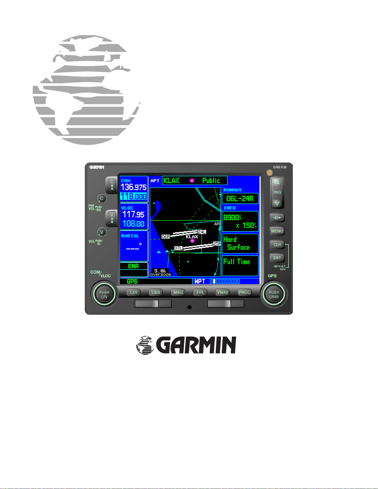
(GNSTM 530 Shown)
Garmin International, Inc.
190-00181-02, Revision G
May 2003
£
© Copyright 1998 - 2003
Garmin Ltd. or its subsidiaries
All Rights Reserved
Except as expressly provided herein, no part of this manual may be reproduced, copied, transmitted, disseminated,
downloaded or stored in any storage medium, for any purpose without the express prior written consent of Garmin.
Garmin hereby grants permission to download a single copy of this manual and of any revision to this manual onto a
hard drive or other electronic storage medium to be viewed and to print one copy of this manual or of any revision
hereto, provided that such electronic or printed copy of this manual or revision must contain the complete text of this
copyright notice and provided further that any unauthorized commercial distribution of this manual or any revision
hereto is strictly prohibited.
Garmin International, Inc.
1200 E. 151
Olathe, KS 66062 USA
st
Street
Telephone: 913-397-8200
Aviation Panel-Mount Technical Support Line (Toll Free): 1-888-606-5482
Web Site Address: www.garmin.com
RECORD OF REVISIONS
Revision Revision
Date
A 2/10/00 Initial Release 12684
B 3/6/00 Add new installation accessory kits. 12845
C 9/22/00 Add unit versions with 14/28 volt transmitter. Update configuration
pages.
D 4/12/01 Add GPS 500 data. Update configuration pages. 15595
E 5/22/02 Add gray unit and 16 watt “A” versions. Update configuration
pages
F 12/13/02 Add Fault Detection and Exclusion
G 5/5/03 Correct 28 volt and 11-33 volt part numbers 21002
Description ECO #
LIST OF EFFECTIVE PAGES
Page Rev.
A ............... G
i................. G
ii................ G
iii............... G
iv............... G
1-1............. G
1-2............. G
1-3............. G
1-4............. G
1-5............. G
1-6............. G
1-7............. G
1-8............. G
2-1............. G
2-2............. G
Page Rev.
2-3............. G
2-4............. G
3-1............. G
3-2............. G
3-3............. G
3-4............. G
3-5............. G
3-6............. G
3-7............. G
3-9............. G
3-11........... G
3-13........... G
3-15........... G
3-17........... G
4-1............. G
Page ...... Rev.
4-2............. G
4-3............. G
4-4............. G
4-5............. G
4-6............. G
4-7............. G
4-8............. G
4-9............. G
4-10........... G
4-11........... G
4-12........... G
4-13........... G
4-14........... G
4-15........... G
4-16........... G
Page Rev.
4-17........... G
4-18........... G
4-19........... G
4-20........... G
4-21........... G
4-23........... G
4-25........... G
4-27........... G
4-29........... G
4-31........... G
4-33........... G
4-35........... G
4-37........... G
4-39........... G
4-41........... G
Page ...... Rev.
4-43 ...........G
4-45 ...........G
4-47 ...........G
4-49 ...........G
4-51 ...........G
4-53 ...........G
4-55 ...........G
4-57 ...........G
4-59 ...........G
4-61 ...........G
4-63 ...........G
4-65 ...........G
4-67 ...........G
4-69 ...........G
5-1 .............G
Page Rev.
5-2 .............G
5-3 .............G
5-4 .............G
5-5 .............G
5-6 .............G
5-7 .............G
5-8 .............G
5-9 .............G
5-10 ...........G
5-11 ...........G
5-12 ...........G
5-13 ...........G
5-14 ...........G
5-15 ...........G
5-16 ...........G
Page Rev.
5-17 ...........G
5-18 ...........G
A-1 ............G
A-2 ............G
A-3 ............G
A-4 ............G
A-5 ............G
A-6 ............G
B-1.............G
B-2.............G
B-3.............G
B-4.............G
B-5.............G
B-6.............G
C-1.............G
14159
18221
19978
Page Rev.
C-2.............G
C-3.............G
C-4.............G
D-1 ............G
D-2 ............G
D-3 ............G
D-4 ............G
E-1............. G
E-2............. G
Page A 500 SERIES INSTALLATION MANUAL
Rev G P/N 190-00181-02

This manual is written for main software version 4.00. Information in this document is subject to change
without notice. Visit the Garmin web site (www.garmin.com) for current updates and supplemental
information concerning the operation of this and other Garmin products.
INFORMATION SUBJECT TO EXPORT CONTROL LAWS
This document may contain information which is subject to the Export Administration Regulations
("EAR") issued by the United States Department of Commerce (15 CFR, Chapter VII, Subchapter C) and
which may not be exported, released, or disclosed to foreign nationals inside or outside of the United States
without first obtaining an export license. A violation of the EAR may be subject to a penalty of up to 10
years imprisonment and a fine of up to $1,000,000 under Section 2410 of the Export Administration Act of
1979. Include this notice with any reproduced portion of this document.
WARNING
This product, its packaging, and its components contain chemicals known to the State of California to
cause cancer, birth defects, or reproductive harm. This Notice is being provided in accordance with
California's Proposition 65. If you have any questions or would like additional information, please refer to
our web site at www.garmin.com/prop65.
500 SERIES INSTALLATION MANUAL Page i
P/N 190-00181-02 Rev G

TABLE OF CONTENTS
1. GENERAL DESCRIPTION
1.1 INTRODUCTION .........................................................................................................................................1-1
1.2 EQUIPMENT DESCRIPTION......................................................................................................................1-1
1.3 TECHNICAL SPECIFICATIONS.................................................................................................................1-1
1.4 LICENSE REQUIREMENTS .......................................................................................................................1-7
1.5 CERTIFICATION .........................................................................................................................................1-7
1.6 FAULT DETECTION AND EXCLUSION (FDE) ......................................................................................1-7
1.7 LIMITED WARRANTY ...............................................................................................................................1-8
2. INSTALLATION
2.1 INTRODUCTION .........................................................................................................................................2-1
2.2 ANTENNA CONSIDERATIONS .................................................................................................................2-1
2.3 RACK CONSIDERATIONS .........................................................................................................................2-3
2.4 CABLING AND WIRING ............................................................................................................................2-3
2.5 COOLING AIR..............................................................................................................................................2-3
2.6 MINIMUM INSTALLATION REQUIREMENTS .......................................................................................2-3
3. INSTALLATION PROCEDURE
3.1 UNIT AND ACCESSORIES.........................................................................................................................3-1
3.2 DATA BASE OPTIONS................................................................................................................................3-3
3.3 MISCELLANEOUS OPTIONS.....................................................................................................................3-3
3.4 INSTALLATION ACCESSORIES REQUIRED BUT NOT PROVIDED ...................................................3-3
3.5 ANTENNA INSTALLATION ......................................................................................................................3-3
3.6 CABLE INSTALLATION.............................................................................................................................3-4
3.7 RACK INSTALLATION...............................................................................................................................3-5
3.8 500 SERIES UNIT INSERTION AND REMOVAL.....................................................................................3-6
3.9 COM ANTENNA INSTALLATION CHECK (GNS 530)............................................................................3-6
3.10 GA 56 ANTENNA INSTALLATION DRAWING.....................................................................................3-7
3.11 MOUNTING RACK DIMENSIONS...........................................................................................................3-9
3.12 MOUNTING RACK INSTALLATION ......................................................................................................3-13
3.13 RECOMMENDED PANEL CUTOUT DIMENSIONS ..............................................................................3-17
4. SYSTEM INTERCONNECTS
4.1 PIN FUNCTION LIST...................................................................................................................................4-1
4.2 POWER, LIGHTING, AND ANTENNAS....................................................................................................4-5
4.3 ALTIMETER.................................................................................................................................................4-6
4.4 MAIN INDICATOR......................................................................................................................................4-7
4.5 ANNUNCIATORS/SWITCHES ...................................................................................................................4-9
4.6 SERIAL DATA .............................................................................................................................................4-11
4.7 COM/VOR/ILS AUDIO (GNS 530 ONLY)..................................................................................................4-14
4.8 VOR/ILS INDICATOR (GNS 530 ONLY)...................................................................................................4-16
4.9 RMI/OBI........................................................................................................................................................4-18
4.10 DME TUNING (GNS 530 ONLY)..............................................................................................................4-19
4.11 500 SERIES INTERCONNECTS................................................................................................................4-21
5. POST INSTALLATION CONFIGURATION & CHECKOUT PROCEDURE
5.1 CONFIGURATION MODE OPERATIONS.................................................................................................5-1
5.2 INSTALLATION CONFIGURATION PAGES............................................................................................5-1
5.3 ADDITIONAL GROUND TESTS ................................................................................................................5-16
Appendix A. CERTIFICATION DOCUMENTS
A.1 CONTINUED AIRWORTHINESS..............................................................................................................A-1
A.2 ENVIRONMENTAL QUALIFICATION FORM—GNS 530......................................................................A-3
A.3 ENVIRONMENTAL QUALIFICATION FORM—GPS 500 ......................................................................A-4
A.4 ENVIRONMENTAL QUALIFICATION FORM—GA 56..........................................................................A-5
Appendix B. STC PERMISSION ..............................................................................................................B-1
Appendix C. 500 SERIES RS-232 AVIATION DATA FORMAT...........................................................C-1
Appendix D. 500 SERIES RS-232 FUEL/AIR DATA INPUT FORMAT ...............................................D-1
Appendix E. 500 SERIES LRU INTERFACE OVERVIEW ....................................................................E-1
Note: Throughout this document references made to GNS 530 shall equally apply to the GNS 530A
except where specifically noted.
Page ii 500 SERIES INSTALLATION MANUAL
Rev G P/N 190-00181-02

LIST OF FIGURES
FIGURE 2-1. GPS ANTENNA INSTALLATION CONSIDERATIONS .................................................................2-2
FIGURE 3-1. COAXIAL CABLE INSTALLATION ................................................................................................3-4
FIGURE 3-2. GA 56 ANTENNA INSTALLATION DRAWING .............................................................................3-7
FIGURE 3-3. GNS 530 MOUNTING RACK DIMENSIONS ...................................................................................3-9
FIGURE 3-4. GPS 500 MOUNTING RACK DIMENSIONS....................................................................................3-11
FIGURE 3-5. GNS 530 MOUNTING RACK INSTALLATION...............................................................................3-13
FIGURE 3-6. GPS 500 MOUNTING RACK INSTALLATION ...............................................................................3-15
FIGURE 3-7. 500 SERIES RECOMMENDED PANEL CUTOUT DIMENSIONS..................................................3-17
FIGURE 4-1. 500 SERIES SYSTEM INTERFACE DIAGRAM ..............................................................................4-21
FIGURE 4-2. GNS 530 TYPICAL INSTALLATION ...............................................................................................4-23
FIGURE 4-3. GPS 500 TYPICAL INSTALLATION................................................................................................4-25
FIGURE 4-4. POWER, LIGHTING, AND ANTENNAS INTERCONNECT...........................................................4-27
FIGURE 4-5. ALTIMETER INTERCONNECT........................................................................................................4-29
FIGURE 4-6. MAIN INDICATOR INTERCONNECT .............................................................................................4-31
FIGURE 4-7. KI 209A MAIN INDICATOR INTERCONNECT ..............................................................................4-33
FIGURE 4-8. KI 208A MAIN INDICATOR INTERCONNECT ..............................................................................4-35
FIGURE 4-9. ANNUNCIATORS/SWITCHES INTERCONNECT ..........................................................................4-37
FIGURE 4-10. RS-232 SERIAL DATA INTERCONNECT .....................................................................................4-39
FIGURE 4-11. ARINC 429 EFIS INTERCONNECT................................................................................................4-41
FIGURE 4-12. ARINC 429 SANDEL EHSI INTERCONN. (1 500 SERIES UNIT, 1 SANDEL SN3308)..............4-43
FIGURE 4-13. ARINC 429 SANDEL EHSI INTERCONNECT (2 GNS 530, 1 SANDEL SN3308).......................4-45
FIGURE 4-14. ARINC 429 SANDEL EHSI INTERCONNECT (2 GNS 530, 2 SANDEL SN3308).......................4-47
FIGURE 4-15. ARINC 429 AIR DATA/IRU/AHRS INTERCONNECT..................................................................4-49
FIGURE 4-16. ARINC 429 FLIGHT CONTROL INTERCONNECT ......................................................................4-51
FIGURE 4-17. TRAFFIC ADVISORY SYSTEM INTERCONNECT ......................................................................4-53
FIGURE 4-18. WEATHER AND TERRAIN INTERCONNECT .............................................................................4-55
FIGURE 4-19. AUDIO PANEL INTERCONNECT..................................................................................................4-57
FIGURE 4-20. VOR/ILS INDICATOR INTERCONNECT ......................................................................................4-59
FIGURE 4-21. RMI/OBI INTERCONNECT.............................................................................................................4-61
FIGURE 4-22. KING SERIAL PANEL DME TUNING INTERCONNECT ............................................................4-63
FIGURE 4-23. KING SERIAL REMOTE DME TUNING INTERCONNECT.........................................................4-65
FIGURE 4-24. PARALLEL 2 OF 5 DME TUNING INTERCONNECT ..................................................................4-67
FIGURE 4-25. PARALLEL BCD/SLIP CODE DME TUNING INTERCONNECT ................................................4-69
FIGURE 5-1. MAIN ARINC 429 CONFIG PAGE....................................................................................................5-1
FIGURE 5-2. MAIN RS-232 CONFIG PAGE ...........................................................................................................5-3
FIGURE 5-3. MAIN INPUTS PAGE.........................................................................................................................5-4
FIGURE 5-4. INSTRUMENT PANEL SELF TEST PAGE ......................................................................................5-5
FIGURE 5-5. MAIN LIGHTING PAGE....................................................................................................................5-5
FIGURE 5-6. MAIN LIGHTING PAGE (DISPLAY LIGHTING FROM LIGHTING BUS) ...................................5-6
FIGURE 5-7. DATE/TIME SETUP PAGE................................................................................................................5-6
FIGURE 5-8. MAIN DISCRETE I/O PAGE..............................................................................................................5-7
FIGURE 5-9. MAIN CDI/OBS CONFIG PAGE........................................................................................................5-8
FIGURE 5-10. COM SETUP PAGE (GNS 530 ONLY)............................................................................................5-10
FIGURE 5-11. VOR DISCRETE INPUTS PAGE (GNS 530 ONLY).......................................................................5-11
FIGURE 5-12. VOR/LOC/GS CDI PAGE (GNS 530 ONLY)...................................................................................5-11
FIGURE 5-13. VOR/LOC/GS ARINC 429 CONFIG PAGE (GNS 530 ONLY).......................................................5-12
FIGURE 5-14. STORMSCOPE CONFIG PAGE.......................................................................................................5-13
FIGURE 5-15. STORMSCOPE TEST PAGE............................................................................................................5-13
FIGURE 5-16. STORMSCOPE DOWNLOAD DATA PAGE ..................................................................................5-14
FIGURE 5-17. TRAFFIC PAGE (SKYWATCH)......................................................................................................5-14
FIGURE 5-18. TRAFFIC PAGE (TCAD)..................................................................................................................5-14
FIGURE 5-19. RYAN TCAD CONFIG PAGE..........................................................................................................5-15
FIGURE 5-20. GAD 42 CONFIG PAGE ...................................................................................................................5-15
FIGURE 5-21. DATA LINK PAGE...........................................................................................................................5-15
Note: Throughout this document references made to GNS 530 shall equally apply to the GNS 530A
except where specifically noted.
500 SERIES INSTALLATION MANUAL Page iii
P/N 190-00181-02 Rev G

500 SERIES HARDWARE MOD LEVEL HISTORY
The following table identifies hardware modification (Mod) Levels for the GPS 500 and GNS 530.
Mod Levels are listed with the associated service bulletin number, service bulletin date, and the purpose of
the modification. The table is current at the time of publication of this manual (see date on front cover) and
is subject to change without notice. Authorized Garmin Sales and Service Centers are encouraged to
access the most up-to-date bulletin and advisory information on the Garmin Dealer Resource web site at
www.garmin.com using their Garmin-provided user name and password.
MOD
LEVEL
1 0019 11/7/00
2 0101 2/16/01
3 0111 7/9/01
4 0203, Rev B 8/12/02
5 0207 4/2/02
6 0211 6/4/02
SERVICE
BULLETIN
NUMBER
SERVICE
BULLETIN
PURPOSE OF MODIFICATION
DATE
Replace fuse in COM circuit with a resistor
Remote COM transfer
Improves VLOC Morse code ident
Improve receiver audio compressor
performance
Remove excess solder from COM board
Reduce input transients from Audio Panel
Page iv 500 SERIES INSTALLATION MANUAL
Rev G P/N 190-00181-02
1. GENERAL DESCRIPTION
1.1 INTRODUCTION
This manual describes the physical, mechanical, and electrical characteristics and the installation
requirements for the 500 Series (GPS 500 and GNS 530) panel-mounted units. After installation of the
500 Series system, FAA Form 337 must be completed by an appropriately certificated agency to return the
aircraft to service.
Note: Throughout this document references made to GNS 530 shall equally apply to the GNS 530A
except where specifically noted.
1.2 EQUIPMENT DESCRIPTION
The 500 Series units are mark width (6.25” wide) units, and 4.60” high. The display is a 320 by 234 pixel
color LCD. The units include two removable data cards, one with a Jeppesen database, and the second
being an optional custom data card.
The GPS 500 is a GPS receiver certifiable for IFR en route, terminal, and non-precision approach
operations.
The GNS 530 includes all the features of the GPS 500, and also includes IFR certified airborne VHF
communications transceiver and an IFR certified airborne VOR/Localizer and Glideslope receivers. The
(A) model is a 28 Vdc unit with a 16 Watt COM transmitter.
GPS signals are received by Garmin's low profile GA 56 antenna (P/N 010-10040-0X).
CAUTION
The 500 Series product lens is coated with a special anti-reflective coating which is very sensitive to skin
oils, waxes and abrasive cleaners. CLEANERS CONTAINING AMMONIA WILL HARM THE ANTIREFLECTIVE COATING. It is very important to clean the lens using an eyeglass lens cleaner which is
specified as safe for anti-reflective coatings and a clean, lint-free cloth.
1.3 TECHNICAL SPECIFICATIONS
The conditions and tests required for TSO approval of the 500 Series are minimum performance standards.
It is the responsibility of those desiring to install this article either on or within a specific type or class of
aircraft to determine that the aircraft installation conditions are within the TSO standards. The article may
be installed only if further evaluation by the applicant documents an acceptable installation and is approved
by the administrator. For TSO Compliance, see Appendix A.
1.3.1 Physical Characteristics
Bezel Height 4.58 in. (116 mm)
Bezel Width 6.25 in. (159 mm)
Rack Height (Dimple-to-dimple) 4.60 in. (117 mm)
Rack Width 6.32 in. (161 mm)
Depth Behind Panel with
Connectors (Measured from
face of aircraft panel to rear of
connector backshells)
GPS 500 Weight (Unit only) 5.5 lbs. (2.5 kg)
GPS 500 Weight (Installed with
rack and connectors)
GNS 530 Weight (Unit only) 6.8 lbs. (3.1 kg)
GNS 530 Weight (Installed with
rack and connectors)
11.00 in. (279 mm)
6.9 lbs. (3.1 kg)
8.5 lbs. (3.9 kg)
500 SERIES INSTALLATION MANUAL Page 1-1
P/N 190-00181-02 Rev G

1.3.2 General Specifications
Operating Temperature Range
-20°C to +55°C. For more details see Environmental
Qualification Form.
Humidity 95% non-condensing
Altitude Range -1,500 ft to 50,000 ft
Input Voltage Range
11 to 33 Vdc
GPS 500 (011-00562-00, -10)
GNS 530 (011-00550-10, -30)
Input Voltage Range
22 to 33 Vdc
GNS 530 (011-00550-00)
Input Voltage Range
28 Vdc
GNS 530A (011-00835-00, -10)
Power Requirements—P5001
(GNS 530 Main Connector)
Power Requirements—P5002
(COM Connector)
1.8 A @ 27.5 Vdc (maximum)
3.6 A @ 13.75 Vdc (maximum)
15 mA @ 27.5 Vdc (not transmitting);
3.0 A @ 27.5 Vdc (transmitting)
GNS 530 (011-00550-00)
GNS 530A (011-00835-00, -10)
Power Requirements—P5002
(COM Connector)
GNS 530 (011-00550-10)
15 mA @ 27.5 Vdc (not transmitting);
3.0 A @ 27.5 Vdc (transmitting)
15 mA @ 13.75 Vdc (not transmitting);
6.0 A @ 13.75 Vdc (transmitting)
Superflag Power Requirements 500 mA max. Per superflag output @ 27.5 Vdc
1.0 A max. @ 27.5 Vdc on P5001 (Main Superflags).
1.0 A max. @ 27.5 Vdc on P5006 (VOR/LOC, G/S
Superflags).
Software RTCA DO-178B level C
Environmental Testing RTCA DO-160C.
For more details see Environmental Qualification Forms.
.
1.3.3 GPS Specifications
Regulatory Compliance TSO C129a Class A(1), RTCA DO-208
Acquisition Time a) Search-the-Sky (without almanac, without initial position
or time): 5 minutes
b) AutoLocate™ (with almanac, without initial position or
time): 5 minutes
c) Cold Start (position known to 300 nm, time known to 10
minutes, with valid almanac): 45 seconds
d) Warm Start (position known to 10 nm, time known to 10
minutes, with valid almanac and ephemeris): 15 seconds
Max Velocity 1000 kts.
Dynamics 6 g
Page 1-2 500 SERIES INSTALLATION MANUAL
Rev G P/N 190-00181-02

1.3.4 COM Transceiver Specifications (GNS 530 Only) **
Regulatory Compliance TSO-C37d Class 4 & 6* (3 & 5 for “A” models),TSO-C38d
Class C & E, JTSO-2C37e, JTSO-2C38e, RTCA DO-186a
ICAO Annex 10 Volume III (Part II – Voice Communications
Systems) Par. 2.3.3
Audio Output
100 mW minimum into a 500 Ω load.
Audio Response Less than 6 dB of Variation between 350 and 2500 Hz.
Audio Distortion The distortion in the receiver audio output shall not exceed
15% at all levels up to 100 mW.
AGC Characteristics The audio output shall not vary by more than 6 dB when the
level of the RF input signal, modulated 30% at 1000 Hz, is
varied from 5 µV to 450,000 µV.
Sensitivity (S+N)/N on all channels shall be greater than 6 dB when the
RF level is 2 µV (hard) modulated 30% at 1000 Hz at rated
audio.
Squelch
2 µv ±6 dB for 25 kHz channels.
3 µv ±6 dB for 8.33 kHz channels.
Selectivity
6 dB BW is greater than ±8 kHz for 25 kHz channeling.
60 dB BW is less than ±25 kHz for 25 kHz channeling.
6 dB BW is greater than ±2.778 kHz for 8.33 kHz channeling.
60 dB BW is less than ±7.37 kHz for 8.33 kHz channeling.
Spurious Response Greater than 85 dB.
Transmitter Power At Least 10 Watts*, 16 watts for “A” models.
Transmitter Duty Cycle Recommended 10% maximum.
Modulation Capability The modulation shall not be less than 70% and not greater
than 98% with a standard modulator signal applied to the
transmitter.
Carrier Noise Level Shall be at least 45 dB (S+N)/N.
Frequency Stability 0.0005%
Demodulated Audio Distortion Less than 10% distortion when the transmitter is modulated
at least 70%.
Sidetone
1.4 V
into a 500 Ω load when the transmitter is modulated
RMS
at least 70%.
Demodulated Audio Response Shall be less than 6 dB when the audio input frequency is
varied from 350 to 2500 Hz.
* C37d Class 4 & 6 may not provide suitable COM transmit range for some high-altitude aircraft.
** Specifications shown apply at nominal input voltages of 13.75 Vdc or 27.5 Vdc, as applicable, and with
a nominal 50 ohm resistive load at the antenna connector.
500 SERIES INSTALLATION MANUAL Page 1-3
P/N 190-00181-02 Rev G

1.3.5 VOR Specifications (GNS 530 Only)
Regulatory Compliance TSO C40c, JTSO-2C40c, RTCA DO-196, EuroCAE ED-22B
ICAO Annex 10 Volume I (Radio Navigation Aids) Par. 3.3.8
Receiver Audio Sensitivity At -103.5 dBm (S+N)/N shall not be less than 6 dB.
Course Deviation Sensitivity -103.5 dBm or less for 60% of standard deflection.
Flag The VOR Course Deviation Flag must be flagged:
a) in the absence of an RF signal.
b) in the absence of the 9960 Hz modulation.
c) in the absence of either one of the two 30 Hz
modulations.
d) When the level of a standard VOR deviation test signal
produces less than a 50% of standard deflection.
AGC Characteristics From -99 dBm to -13 dBm input of a Standard VOR Audio
Test Signal, audio output levels shall not vary more than 3
dB.
Spurious Response Greater than 80 dB.
VOR OBS Bearing Accuracy The bearing information as presented to the pilot shall not
have an error in excess of 2.7° as specified by RTCA DO-196
and EuroCAE ED-22B.
Audio Output
A minimum 100 mW into a 500 Ω load.
Audio Response Less than 6 dB of variation between 350 and 2500 Hz.
Except the 1020 Hz Ident Tone is at least 20 dB down in
voice mode.
Audio Distortion The distortion in the receiver audio output shall not exceed
10% at all levels up to 100 mW.
Page 1-4 500 SERIES INSTALLATION MANUAL
Rev G P/N 190-00181-02

1.3.6 LOC Specifications (GNS 530 Only)
Regulatory Compliance TSO C36e, JTSO-C36e, RTCA DO-195 Class A, EuroCAE
ED-46B
Annex 10 Volume I (Radio Navigation Aids) Par. 3.1.4
Receiver Audio Sensitivity At -103.5 dBm (S+N)/N shall not be less than 6 dB.
Course Deviation Sensitivity -103.5 dBm or less for 60% of standard deflection.
Flag The LOC Course Deviation Flag must be flagged:
a) in the absence of an RF signal.
b) When either the 90 or 150 Hz modulating signals is
removed and the other is maintained at its normal 20%.
c) In the absence of both 90 and 150 Hz modulation.
d) When the level of a standard localizer deviation test
signal produces less than a 50% of standard deflection.
AGC Characteristics From -86 dBm and -33 dBm input of a Standard VOR Audio
Test Signal, audio output levels shall not vary more than 3
dB.
Selectivity Nose Bandwidth: The input signal level required to produce
the reference AGC voltage shall not vary more than 6 dB
over the input signal frequency range of ± 9 kHz from the
assigned channel frequency.
Skirt Bandwidth: The input signal level required to produce
reference AGC voltage shall be at least 70 dB greater than
the level required to produce reference AGC voltage at the
assigned channel frequency at ± 36 kHz from the assigned
channel frequency.
Spurious Response Greater than 80 dB.
Centering Accuracy
Audio Output
Typical 0 ± 3 mV (Max error 9.9 mV per RTCA DO-195).
A minimum 100 mW into a 500 Ω load.
Audio Response Less than 6 dB of Variation between 350 and 2500 Hz.
Except the 1020 Hz Ident Tone is at least 20 dB down in
voice mode.
Audio Distortion The distortion in the receiver audio output shall not exceed
10% at all levels up to 100 mW.
500 SERIES INSTALLATION MANUAL Page 1-5
P/N 190-00181-02 Rev G

1.3.7 Glideslope Specifications (GNS 530 Only)
Regulatory Compliance TSO C34e, JTSO-C34e, RTCA DO-192, EuroCAE ED-47B
Sensitivity -87 dBm or less for 60% of standard deflection.
Centering Accuracy
Selectivity
0 ±.0091 ddm or 0 ±7.8 mV.
The course deviation shall be 0 ddm ±.0091ddm when using
the Glideslope Centering Test Signal as the RF frequency is
varied ±17 kHz from the assigned channel.
At frequencies displaced by ±132 kHz or greater, the input
signal shall be at least 60 dB down.
Standard deflection a) With a standard deflection ‘FLY DOWN’ condition (90 Hz
dominant), the output shall be -78 mV ±7.8 mV.
b) With a standard deflection ‘FLY UP’ condition (150 Hz
dominant), the output shall be +78 mV ±7.8 mV.
Flag The unit Flags:
a) When the level of a standard deviation test signal
produces 50% or less of standard deflection of the deviation
indicator.
b) In the absence of 150 Hz modulation.
c) In the absence of 90 Hz modulation.
d) In the absence of both 90 Hz and 150 Hz modulation.
e) In the absence of RF.
Page 1-6 500 SERIES INSTALLATION MANUAL
Rev G P/N 190-00181-02

1.4 LICENSE REQUIREMENTS
The following guidance is provided to help ensure the proper licensing of the GNS 530 COM within the
United States and its territories. Outside the United States, the operator must verify compliance with any
applicable communications regulations for the area in which the equipment is operated.
1. The Telecommunications Act of 1996 effective February 8, 1996 provides the FCC discretion to
eliminate radio station license requirements for aircraft. At present, an individual license to operate
the 500 Series unit aboard a private aircraft is not needed in many circumstances. Please see FCC Fact
Sheet PR5000 or contact the FCC at 1-800-322-1117 for more information.
2. No license change is required for an aircraft which already has a station license per FCC 404
Instructions dated 1994.
3. If an aircraft license is required or desired, contact the FCC at 1-800-322-1117 to request FCC Form
404, “Application for Aircraft Radio Station License,” to apply for FCC authorization. The FCC also
has a “Fax on Demand” service to provide forms by FAX at 202-418-0177.
This equipment has been type accepted by the FCC. The bandwidth/emission designator is 6K00 A3E.
CAUTION
THE VHF TRANSMITTER IN THIS EQUIPMENT IS GUARANTEED TO MEET FEDERAL
COMMUNICATIONS COMMISSION ACCEPTANCE OVER THE OPERATING TEMPERATURE
RANGE. MODIFICATIONS NOT EXPRESSLY APPROVED BY GARMIN COULD INVALIDATE
THE LICENSE AND MAKE IT UNLAWFUL TO OPERATE THE EQUIPMENT.
1.5 CERTIFICATION
The GPS receivers in the 500 Series units are certified for IFR enroute, terminal, and non-precision
approaches. The 500 Series initial certification was accomplished via STC’s by Garmin in a Piper PA32.
See Appendix B for copies of the STC’s.
The 500 Series units have been qualified to RTCA/DO-160 Section 22 lightning requirements. Special
installation considerations are required, refer to the Environmental Qualification Forms in Appendix A.
1.6 FAULT DETECTION AND EXCLUSION (FDE)
NOTE
The 500 Series equipment as installed has been found to comply with the requirements for GPS
primary means of navigation in oceanic and remote airspace, when used in conjunction with the
500 Series Trainer Program incorporating the FDE Prediction Program. This does not constitute
an operational approval.
The Garmin 500 Series Main and GPS Software version 3.00 and higher incorporate Fault Detection and
Exclusion (FDE) display interface and control, satisfying the requirements for GPS as a Primary Means of
Navigation for Oceanic/Remote Operations per FAA Notice N8110.60.
Fault Detection and Exclusion consists of two parts. The fault detection function detects a satellite failure
that can affect navigation. The exclusion function refers to the capability of excluding one or more failed
satellites and preventing them from affecting navigation.
FDE is provided for Oceanic and Remote Operations, non-precision approaches, en route and terminal
phases of flight. FDE for non-oceanic flight phases adhere to the same missed alert probability, false alert
probability, and failed exclusion probability specified by N8110.60.
500 SERIES INSTALLATION MANUAL Page 1-7
P/N 190-00181-02 Rev G

The FDE function is built into the GPS 500/GNS 530 and does not require pilot interaction. In contrast,
the FDE Prediction Program does require pilot interaction and must be used prior to oceanic/remote area
flights to predict FDE availability.
The 500 Series Trainer software includes an FDE Prediction Program to meet the requirements for GPS as
a primary means of navigation for oceanic/remote operations per N8110.60. The oceanic flight phase
occurs on the GPS 500/GNS 530 when more than 200 nautical miles from the nearest airport.
All operators using the GPS 500/GNS 530 as primary means of navigation in oceanic/remote areas under
FAR parts 91, 121, 125 and 135 must utilize the FDE Prediction Program prior to conducting a flight in
these areas.
1.7 LIMITED WARRANTY
This Garmin product is warranted to be free from defects in materials or workmanship for one year from
the date of purchase. Within this period, Garmin will at its sole option, repair or replace any components
that fail in normal use. Such repairs or replacement will be made at no charge to the customer for parts or
labor, provided that the customer shall be responsible for any transportation cost. This warranty does not
cover failures due to abuse, misuse, accident or unauthorized alteration or repairs.
THE WARRANTIES AND REMEDIES CONTAINED HEREIN ARE EXCLUSIVE AND IN LIEU OF
ALL OTHER WARRANTIES EXPRESS OR IMPLIED OR STATUTORY, INCLUDING ANY
LIABILITY ARISING UNDER ANY WARRANTY OF MERCHANTABILITY OR FITNESS FOR A
PARTICULAR PURPOSE, STATUTORY OR OTHERWISE. THIS WARRANTY GIVES YOU
SPECIFIC LEGAL RIGHTS, WHICH MAY VARY FROM STATE TO STATE.
IN NO EVENT SHALL GARMIN BE LIABLE FOR ANY INCIDENTAL, SPECIAL, INDIRECT OR
CONSEQUENTIAL DAMAGES, WHETHER RESULTING FROM THE USE, MISUSE, OR
INABILITY TO USE THIS PRODUCT OR FROM DEFECTS IN THE PRODUCT. Some states do not
allow the exclusion of incidental or consequential damages, so the above limitations may not apply to you.
Garmin retains the exclusive right to repair or replace the unit or software or offer a full refund of the
purchase price at its sole discretion. SUCH REMEDY SHALL BE YOUR SOLE AND EXCLUSIVE
REMEDY FOR ANY BREACH OF WARRANTY.
To obtain warranty service, contact your local Garmin Authorized Service Center. For assistance in
locating a Service Center near you, call Garmin Customer Service at one of the numbers shown below.
Products sold through online auctions are not eligible for rebates or other special offers from Garmin.
Online auction confirmations are not accepted for warranty verification. To obtain warranty service, an
original or copy of the sales receipt from the original retailer is required. Garmin will not replace missing
components from any package purchased through an online auction.
Garmin International, Inc. Garmin (Europe) Ltd.
1200 East 151
st
Street Unit 4, The Quadrangle, Abbey Park Industrial Estate
Olathe, Kansas 66062, U.S.A. Romsey, SO51 9DL, U.K.
Phone: 913/397.8200 Phone: 44/1794.519944
FAX: 913/397.0836 FAX: 44/1794.519222
Page 1-8 500 SERIES INSTALLATION MANUAL
Rev G P/N 190-00181-02

2. INSTALLATION
2.1 INTRODUCTION
Careful planning and consideration of the suggestions in this section are required to achieve the desired
performance and reliability from the 500 Series unit. Any deviations from the installation instructions
prescribed in this document shall be accomplished in accordance with the requirements set forth in FAA
AC 43.13-2A, and 14 CFR Part 43 Maintenance, Preventive Maintenance, Rebuilding, and Alteration.
2.2 ANTENNA CONSIDERATIONS
Antenna installations on pressurized cabin aircraft require FAA approved installation design and
engineering substantiation data whenever such antenna installations incorporate alteration (penetration) of
the cabin pressure vessel by connector holes and/or mounting arrangements. For needed engineering
support pertaining to the design and approval of such pressurized aircraft antenna installations, it is
recommended that the installer proceed according to any of the following listed alternatives:
1. Obtain approved antenna installation design data from the aircraft manufacturer.
2. Obtain an FAA approved STC, pertaining to, and valid for the antenna installation.
3. Contact the FAA Aircraft Certification Office in the appropriate Region and request identification of
FAA Designated Engineering Representatives (DERs) who are authorized to prepare and approve the
required antenna installation engineering data.
4. Obtain FAA Advisory Circular AC-183C and identify a DER from the roster of individuals in it.
5. Contact an aviation industry organization such as the Aircraft Electronics Association for assistance.
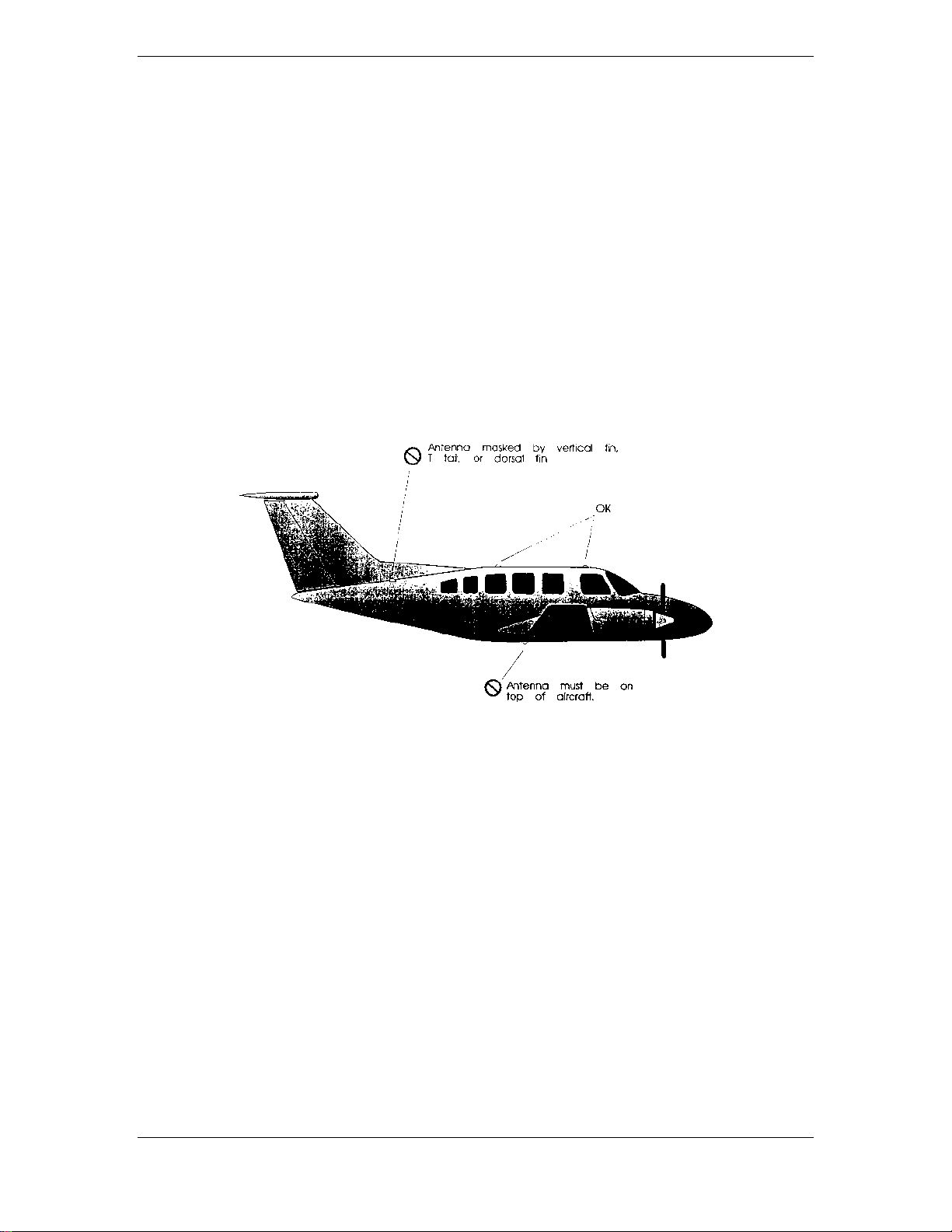
2.2.1 GPS ANTENNA LOCATION
The GA 56 Antenna must be mounted on top of the aircraft. For best performance, select a location with
an unobstructed view of the sky above the aircraft when in level flight. Figure 2-1 illustrates a typical GPS
antenna installation. The antenna should be located at least three feet from transmitting antennas such as
VHF COM, HF transmitter, DME, Transponder and Radar.
For rotorcraft, locate the GA 56 Antenna as far as possible from the main rotor hub. This reduces the
percentage of time the blade blocks the antenna. Also mount it as far below the blade surface as possible if
installing the antenna under the blade. This reduces signal distortion caused by the blades.
2.2.2 COM ANTENNA LOCATION
The GNS 530 COM antenna should be well removed from all projections, engines and propellers. The
ground plane surface directly below the antenna should be a flat plane over as large an area as possible (18
inches square, minimum). The antenna should be mounted a minimum of six feet from any DME or other
COM antennas, four feet from any ADF sense antennas, and three feet from the 500 Series and its GPS
antenna.
If simultaneous use of two COM transceivers is desired (Spit-COM or simulcomm), use of the TX
interlock function is mandatory. In addition, the COM antennas should be spaced for maximum isolation.
A configuration of one topside antenna and one bottom side antenna is recommended.
2.2.3 VOR/LOC ANTENNA LOCATION
The GNS 530 VOR/LOC antenna should be well removed from all projections, engines and propellers. It
should have a clear line of sight if possible. The antenna must be mounted along the centerline of the
aircraft, minimizing the lateral offset.
2.2.4 GLIDESLOPE ANTENNA LOCATION
The GNS 530 Glideslope antenna should be well removed from all projections, engines and propellers. It
should have a clear line of sight if possible.
2.2.5 ELECTRICAL BONDING
No special precautions need to be taken to provide a bonding path between the GPS antenna and the
aircraft structure. Follow the manufacturers’ instructions for the COM, VOR/LOC and Glideslope
antennas.
500 SERIES INSTALLATION MANUAL Page 2-1
P/N 190-00181-02 Rev G
2.2.6 ANTENNA LIMITATIONS
Garmin’s GA 56 Antennas are recommended for installations where the airspeed of the aircraft is subsonic.
In such installations, GA 56—Mod 1 or later—must be used. See the COM, VOR/LOC, and Glideslope
antenna specifications for their limitations.
2.2.7 VHF COM INTERFERENCE OF GPS
On many panel-mounted installations, VHF COM transceivers can radiate strong harmonics from the
transceiver and its antenna. The 500 Series COM does not interfere with its own GPS section. However,
placement of the GA 56 GPS antenna relative to a COM transceiver and COM antenna, including the GNS
530 COM antenna, is critical.
Use the following guidelines, in addition to others in this document, when locating the 500 Series unit and
its antennas.
• GPS Antenna—Locate as far as possible from all COM antennas and all COM transceivers
(including the 500 Series COM). The GPS antenna i much less sensitive to COM antennas that
use a 1.57542 GHz notch filter.
• Locate the 500 Series unit as far as possible from all COM antennas.
Figure 2-1. GPS Antenna Installation Considerations
If a COM antenna is found to be the problem, a 1.57542 GHz notch filter (Garmin P/N 330-00067-00) may
be installed in the VHF COM coax, as close to the COM as possible. This filter is not required for the
GNS 530 transmitter.
If a COM is found to be radiating, the following can be done:
1. Replace or clean VHF COM rack connector to ensure good coax ground.
2. Place a grounding brace between the 500 Series unit, VHF COM and ground.
3. Shield the VHF COM wiring harness.
2.2.8 COM, VOR/LOC, and Glideslope Antenna Installation Instructions
Install the COM, VOR/LOC, and Glideslope antennas according to the manufacturer’s recommendations.
Avoid running other wires and coaxial cables near the VOR/LOC antenna cable.
Page 2-2 500 SERIES INSTALLATION MANUAL
Rev G P/N 190-00181-02

2.3 RACK CONSIDERATIONS
Plan a location which gives the pilot complete and comfortable access to the entire keypad and which is
plainly visible from the pilot’s perspective. Installation of remote switches and annunciators may not be
required if the 500 Series unit is installed in the pilot’s normal field of view (refer to the FAA letter in
Appendix B).
Check that there is adequate depth for the rack in the instrument panel. A location away from heating
vents or other sources of heat generation is optimal.
2.4 CABLING AND WIRING
Coaxial cable with 50 Ω nominal impedance and meeting applicable aviation regulations should be used
for the installation. A typical maximum cable length for the GPS antenna is 40 feet. The installer should
insure that the attenuation does not exceed 10 dB at 1.5 GHz for the specific installation.
Check that there is ample space for the cabling and mating connectors. Avoid sharp bends in cabling,
particularly the COM antenna cable, and routing near aircraft control cables. Cabling for the 500 Series
unit should not be routed near components or cabling which are sources of electrical noise. Do not route
the COM antenna cable near any ADF antenna cables. Route the GPS, VOR/LOC, and Glideslope antenna
cables as far as possible away from all COM transceivers and antenna cables.
2.5 COOLING AIR
The 500 Series units meet all TSO requirements without external cooling. However, as with all electronic
equipment, lower operating temperatures extend equipment life. On the average, reducing the operating
temperature by 15-20 °C (25 to 35 °F) doubles the mean time between failure (MTBF). Recommended
airflow rating is 1 CFM (cubic foot per minute) at a pressure equivalent to 0.1 inches of water.
Potential damage to your 500 Series unit may occur by using outside forced air to cool the equipment.
Therefore, it is recommended that an electric forced air fan be installed, of the indicated rating, to cool this
equipment.
Units tightly packed in the avionics stack heat each other through radiation, convection, and sometimes by
direct conduction. Even a single unit operates at a much higher temperature in still air than in moving air.
Fans or some other means of moving the air around electronic equipment are usually a worthwhile
investment. A 5/8” diameter air fitting is provided on the rear of the mounting rack for the purpose of
admitting cooling air under such conditions. If a form of forced air cooling is installed, make certain that
rainwater cannot enter and be sprayed on the equipment.
2.6 MINIMUM INSTALLATION REQUIREMENTS
Below is a list of required devices for TSO C129a category A1 and A2 certification. For a specific list of
equipment used in the initial STC, obtain a copy of “GNS 530 in Piper PA32 Documented Installation”
(P/N 190-00181-06). Deviations from that set of equipment should be approved by the FAA or the
governing organization.
Pressure Altitude Device
This device delivers pressure altitude data to the 500 Series unit. This data can come from a parallel
encoding altimeter, blind encoder, serializer, or an air data system.
Manual Course Device (Required for GNS 530 Only)
This device delivers the manual course select to the 500 Series unit, which is required for the GNS 530
VOR receiver, and optional for the 500/530 GPS receiver. Course information can come from an analog
resolver, or from an EFIS/EHSI via ARINC 429 serial data.
HSI/CDI Indicator or EFIS
This device displays Nav Flag, Left/Right, To/From, Glideslope Flag, and Up/Down. The indicator(s)
used in conjunction with the GNS 530 VOR/ILS receivers shall be TSO'd.
500 SERIES INSTALLATION MANUAL Page 2-3
P/N 190-00181-02 Rev G

Qualified GPS Antenna
This antenna must be one of those listed in the accessories list, or meet the following requirements:
1. DO-160C Environmental Conditions
The antenna shall meet the environmental conditions listed below and shall conform to the test
requirements of RTCA DO-160C.
Environmental Condition Category Description
Temperature (operating) F2 -55 to +70oC
(ground survival) F2 -55 to +85
Altitude F2 55,000 feet
Temperature Variation A 10
o
Humidity C 95% at +55
o
C
C per minute
o
C
Vibration CLMY Turbo/Reciprocating/Helicopter
Waterproofness S Continuous Stream
Fluids F Deicing Fluid
Lightning 2A Direct Effects
Icing C 0.15” thick
2. Electrical Characteristics
LNA Supply voltage 4.5 ±0.5 Vdc
LNA Supply Current 20 mA Maximum
LNA Operating Frequency 1575.42 ± 2.00 MHz
LNA Gain 20 dB Maximum, 12dB Minimum
LNA Noise Figure 3.0 dB Maximum
LNA Output VSWR (50 Ω)2:1 Maximum
LNA Input power at -1 dB Gain Compression -6 dB Minimum
LNA Bandwidth
(-3 dB) 40 MHz Maximum
(-20 dB) 100 MHz Maximum
(-40 dB) 250 MHz Maximum
3. Radiation Characteristics
Polarization RHCP
Operating Frequency 1575.42 ± 2.00 MHz
Gain (on axis) 2.0 dBic Minimum
(at 160
o
beam width) -6.0 dBic Minimum
Cross Pole Gain (LHCP)
(on axis) -8 dBic Maximum
o
(at 160
beam width) -9 dBic Maximum
4. Mounting Requirements
Cable connection BNC Female
Mounting studs Four 8-32 UNC-2A studs 0.50” long
Page 2-4 500 SERIES INSTALLATION MANUAL
Rev G P/N 190-00181-02
3. INSTALLATION PROCEDURE
3.1 UNIT AND ACCESSORIES
The GNS 530 units are available under the following part numbers:
3.1.1 GNS 530
CATALOG
P/N
010-00182-00 011-00550-00 N N BLACK 28 10 W
010-00182-01 011-00550-00 N Y BLACK 28 10 W
010-00182-10 011-00550-10 N N BLACK 14 or 28 Vdc 10 W
010-00182-11 011-00550-10 N Y BLACK 14 or 28 Vdc 10 W
010-00182-30 011-00550-30 N N GRAY 14 or 28 V (2) 10 W
010-00182-31 011-00550-30 N Y GRAY 14 or 28 V (2) 10 W
010-00285-00 011-00835-00 Y N BLACK 28 Vdc 16 W
010-00285-01 011-00835-00 Y Y BLACK 28 Vdc 16 W
010-00285-10 011-00835-10 Y N GRAY 28 Vdc (2) 16 W
010-00285-11 011-00835-10 Y Y GRAY 28 Vdc (2) 16 W
1) The following accessories are included with the GNS 530 for those indicated with a “Y” above:
MOUNTING RACK (115-00345-00)
CONNECTOR KIT (011-00351-00)
BACK PLATE ASSEMBLY (011-00671-00)
GNS 530 PRODUCT INFO KIT (K00-00060-00)
UNIT
P/N
GNS
530A
ACCESSORIES
(1)
COLOR OPERATING
VOLTAGE
MINIMUM
XMIT PWR
2) Denotes alternate (secondary) power input available, (review installation drawing).
NOTE
The connector kit 011-00351-0x includes a single 78-pin high-density D connector for P5001. The second
78-pin connector on the back of the 500 Series unit (P5050) is for future expansion and is not used at this
time. There is a separate P5050 connector kit (011-00558-00) not included with the 500 Series units.
The GPS 500 units are available under the following part numbers:
3.1.2 GPS 500
CATALOG
P/N
010-00176-00 011-00562-00 N BLACK N
010-00176-01 011-00562-00 Y BLACK N
010-00176-10 011-00562-10 N GRAY Y
010-00176-11 011-00562-10 Y GRAY Y
1) The following accessories are included with the GNS 500 for those indicated with a “Y” above:
MOUNTING RACK (115-00345-00)
CONNECTOR KIT (011-00351-03)
BACK PLATE ASSEMBLY (011-00671-01)
GNS 500 PRODUCT INFO KIT (K00-00060-01)
UNIT
P/N
ACCESSORIES
(1)
COLOR ALT PWR
AVAILABL
E
500 SERIES INSTALLATION MANUAL Page 3-1
P/N 190-00181-02 Rev G
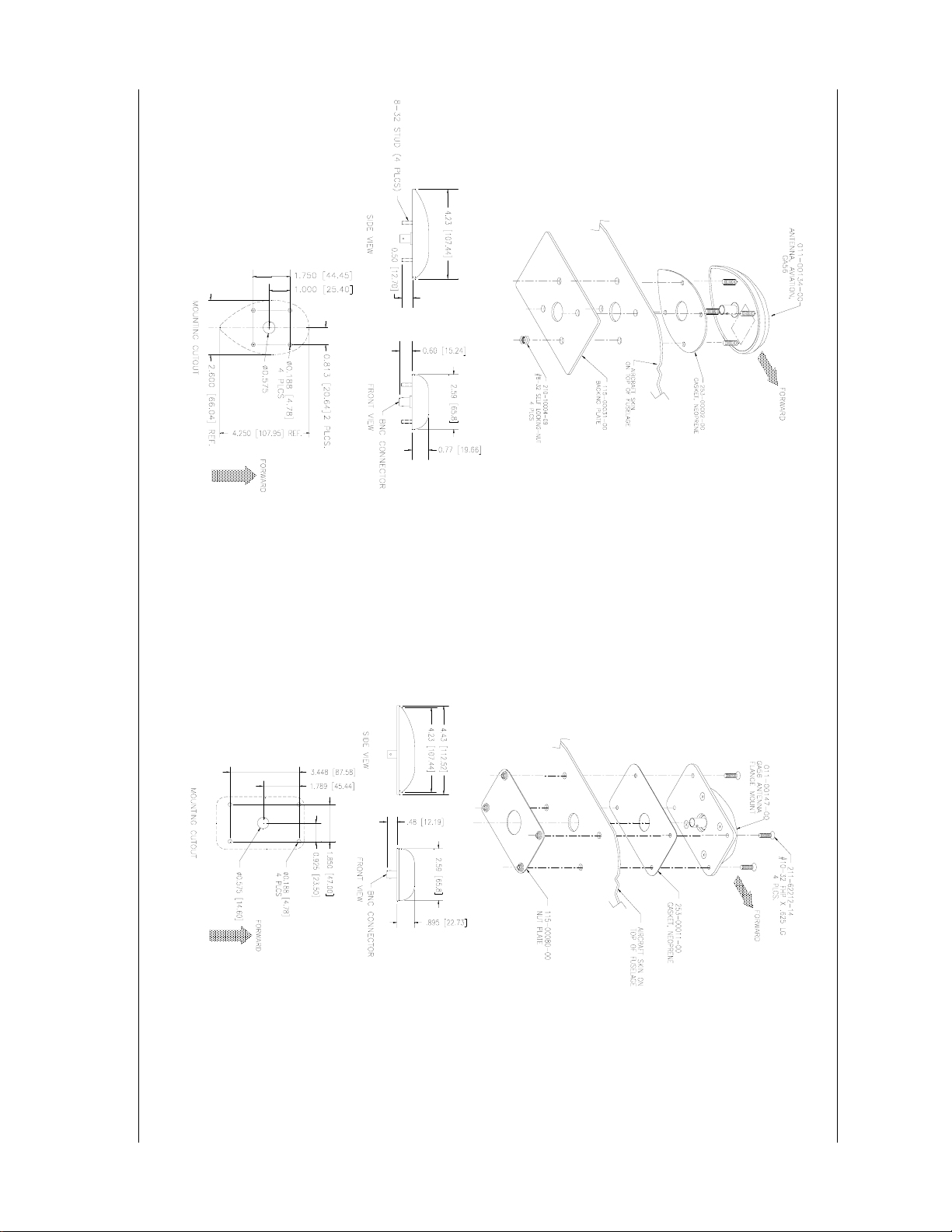
The following installation accessories are available:
1. GPS Antenna Options:
• GA 56 Antenna Kit, without cable (Mod 1 or later, Garmin P/N 010-10040-01).
• This kit contains the following items:
ITEM GARMIN P/N QTY
GA 56 ANTENNA SUB-ASSEMBLY 011-00134-00 1
BACKING PLATE 115-00031-00 1
NUT, SELF-LOCKING, #8-32 210-10004-09 4
ANTENNA GASKET 253-00002-00 1
• GA 56 Flange Mount Antenna Kit (Mod 1 or later, Garmin P/N 010-10040-02).
• This kit contains the following items:
ITEM GARMIN P/N QTY
FLANGE MOUNT GA 56 ANTENNA
SUB-ASSEMBLY
NUT PLATE 115-00080-00 1
SCREW, #10-32 x 5/8” 211-62212-14 4
ANTENNA GASKET 253-00011-00 1
2. Other accessories include the following:
011-00147-00 1
ITEM GARMIN P/N
MOUNTING RACK, 500/530 115-00345-00
P5050 CONNECTOR KIT 011-00558-00
GPS 500 PILOT’S GUIDE 190-00181-60
GPS 500 QUICK REFERENCE GUIDE 190-00181-61
GPS 500 SAMPLE AIRPLANE FLIGHT
MANUAL SUPPLEMENT
GNS 530 PILOT’S GUIDE 190-00181-00
GNS 530 QUICK REFERENCE GUIDE 190-00181-01
GNS 530 SAMPLE AIRPLANE FLIGHT
MANUAL SUPPLEMENT
190-00181-64
190-00181-04
NOTE
A mounting rack is required for approved installations. The following hardware is required for installation
of the mounting rack, but is not provided--#6-32 Flat Head Screw (6 ea.), #6-32 Self-locking Nut (6 ea.).
Page 3-2 500 SERIES INSTALLATION MANUAL
Rev G P/N 190-00181-02
3.2 DATA BASE OPTIONS
ITEM GARMIN P/N
DATA CARD, WORLD WIDE 010-10201-00
DATA CARD, AMERICAS 010-10201-01
DATA CARD, INTERNATIONAL 010-10201-02
3.3 MISCELLANEOUS OPTIONS
ITEM GARMIN P/N
CONNECTOR, BNC, MALE, CLAMP 330-00087-00
LOW-LOSS AVIATION ANTENNA
EXTENSION CABLE WITH RIGHT
ANGLE BNC CONNECTOR, 15 FT.
LOW-LOSS AVIATION ANTENNA
EXTENSION CABLE WITH RIGHT
ANGLE BNC CONNECTOR, 30 FT.
GPS 1.57542 GHz NOTCH FILTER 330-00067-00
320-00003-00
320-00003-02
3.4 INSTALLATION ACCESSORIES REQUIRED BUT NOT PROVIDED
The following installation accessories are required but not provided:
COM Antenna: (GNS 530 Only) Shall meet TSO C37() and C38(). Broad band,
50 Ω, vertically polarized with coaxial cable
VOR/LOC Antenna: (GNS 530 Only) Shall meet TSO C40() and C36(). Broad band, 50 Ω,
horizontally polarized with coaxial cable
Glideslope Antenna: (GNS 530 Only) Shall meet TSO C34(). Broad band, 50 Ω, horizontally polarized
with coaxial cable or low-loss splitter used with the VOR/LOC antenna
Headphones: (GNS 530 Only) 500 Ω nominal impedance
Microphone: (GNS 530 Only) Low impedance, carbon or dynamic, with transistorized pre-amp
3.5 ANTENNA INSTALLATION
For the COM, VOR/LOC, and Glideslope antennas, follow the manufacturers’ instructions.
The remainder of this section applies to the GPS antenna. The GA 56 antenna outline and footprint
dimensions are shown in Figure 3-2, page 3-7.
1. Using the backing plate as a template, mark the location of the mounting holes and the through
hole for coaxial cable. Drill or punch the holes.
2. The antenna installation must provide adequate support for the antenna considering a maximum
drag load of 5 lbs. For the GA 56 antennas (at subsonic speed). Install a doubler plate to
reinforce thin-skinned aircraft. Observe guidelines for acceptable installation practices as
outlined in AC 43.13-2A.
3. Seal the antenna and gasket to the fuselage using a good quality electrical grade sealant. Use
caution to insure that the antenna connector is not contaminated with sealant. Insure that the
mounting screws are fully tightened and that the antenna base is well seated against the gasket.
CAUTION
Do not use construction grade RTV sealant or sealants containing acetic acid. These sealants may damage
the electrical connections to the antenna. Use of these type sealants may void the antenna warranty.
500 SERIES INSTALLATION MANUAL Page 3-3
P/N 190-00181-02 Rev G
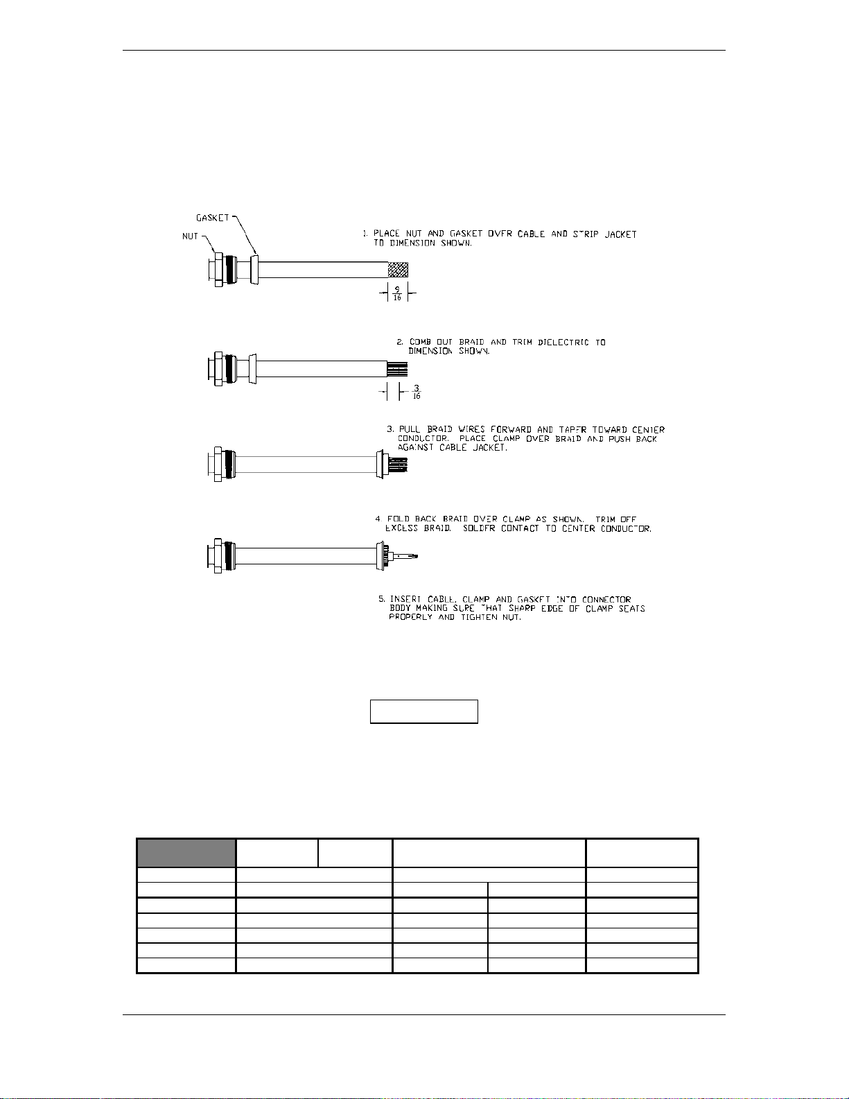
3.6 CABLE INSTALLATION
1. Route the coaxial cable to the rack location keeping in mind the recommendations of Section 2.
Secure the cable in accordance with good aviation practice.
2. Trim the coaxial cable to the desired length and install the BNC connector (330-00087-00) per
the cabling instructions on Figure 3-1. If the connector is provided by the installer, follow the
connector manufacturer’s instructions for cable preparation.
Figure 3-1. Coaxial Cable Installation
3. The card-edge connector may be used to terminate shield grounds to the 500 Series back plate.
CAUTION
4. Feed wires through the connector backshells before insertion into the 78, 44, and 25 pin connectors.
5. Contacts for the 78, 44 and 25 pin connectors must be crimped onto the individual wires of the aircraft
wiring harness. The following tables list contact part numbers (for reference) and recommended crimp
tools:
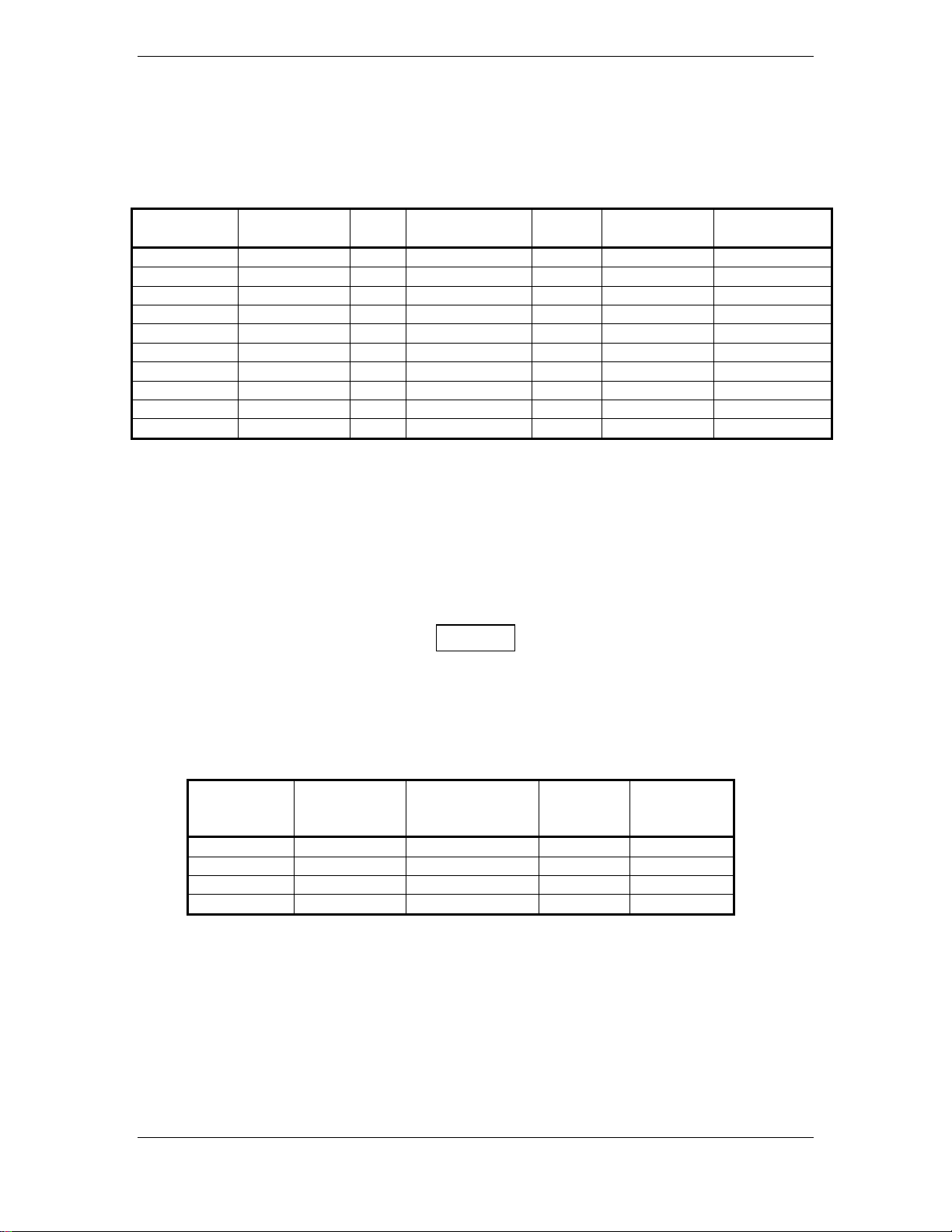
Table 3-1. Pin Contact Part Numbers
78 pin conn
(P5001/5008)
Connector Type High Density Pin Contact Standard Density Socket Contact .1” Pitch Card-edge
Wire Gauge 22-24 AWG 18 AWG 20-24 AWG 20-24 AWG
Garmin P/N 336-00021-00 336-00023-00 336-00022-00 336-00029-00
Military P/N M39029/58-360 N/A M39029/63-368 N/A
AMP 204370-2 N/A 205090-1 583853-4
Positronic M39029/58-360 FC6018D M39029/63-368 N/A
ITT Cannon 030-2042-000 See Note 3 031-1007-042 N/A
Page 3-4 500 SERIES INSTALLATION MANUAL
Rev G P/N 190-00181-02
44 pin conn
(P5006)
25 pin connector (P5002) Shield ground
connector
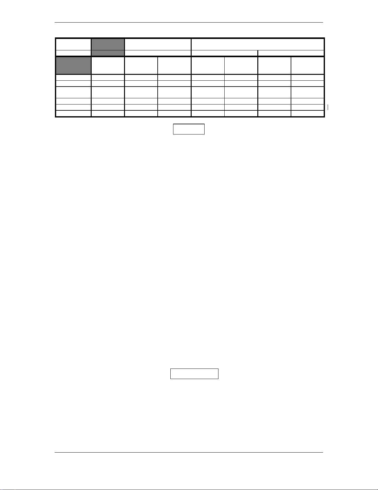
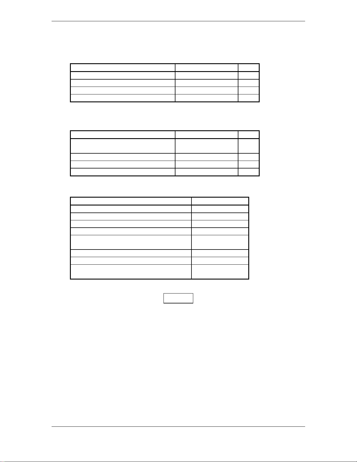
Table 3-2. Recommended Crimp Tools (or equivalent)
Connector
Type
Wire Gauge 22-24 AWG 18 AWG 20-24 AWG
Hand
Crimping
Tool
Military P/N M22520/2-01 M22520/2-09 M81969/1-04 N/A M81969/1-02 M22520/2-08 M81969/1-02
Positronic 9507 9502-3 M81969/1-04 9502-11 M81969/1-02 9502-5 M81969/1-02
ITT Cannon 995-0001-
584
AMP 601966-1 601966-6 91067-1 N/A N/A 601966-5 91067-2
Daniels AFM8 K42 M81969/1-04 K774 M81969/1-02 K13-1 M81969/1-02
Astro 615717 615725 M81969/1-04 N/A M81969/1-02 615724 M81969/1-02
High Density Standard Density
Positioner Insertion/
995-0001-
739
Extraction
Tool
N/A N/A N/A 995-0001-
Positioner Insertion/
Extraction
Tool
Positioner Insertion/
604
Extraction
Tool
980-2000-
426
NOTES
1. Insertion/extraction tools from ITT Cannon are all plastic; others are plastic with metal tip.
2. Non-Garmin part numbers shown are not maintained by Garmin and consequently are subject to change
without notice.
3. Alternate contacts for 18 AWG wire: As an alternative to the Positronic contacts listed (and provided in
the installation kit), the installer may use contacts made by ITT Cannon under P/N 031-1007-001. These
contacts require the use of a different crimp tool positioner than shown in the table, with the part numbers
as follows: Daniels P/N K250, Astro P/N 616245, or ITT Cannon P/N 980-0005-722.
4. For the card-edge connector pin contacts, use AMP part number 90272-1 or equivalent crimping tool.
To prevent a possible short across the pins in the wiring harness, Teflon shrink tubing P/N
312-00005-05, provided in Connector Kit 011-00351-00 (P4002) covers the oversized power and
ground pin contacts P/N 336-00023-00 (pins 11, 12, 21, 22) that protrude from the back of the
connector shell. Before crimping the pins onto the wire:
1. Cut the tubing (312-00005-05) into 4 equal lengths.
2. Slide a short piece of the tubing over the wire.
3. Strip the wire and crimp the pin (336-00023-00) onto the wire.
4. Insert the pin into the connector shell.
5. Slide the tubing over the exposed portion of the pin and shrink using a heat gun.
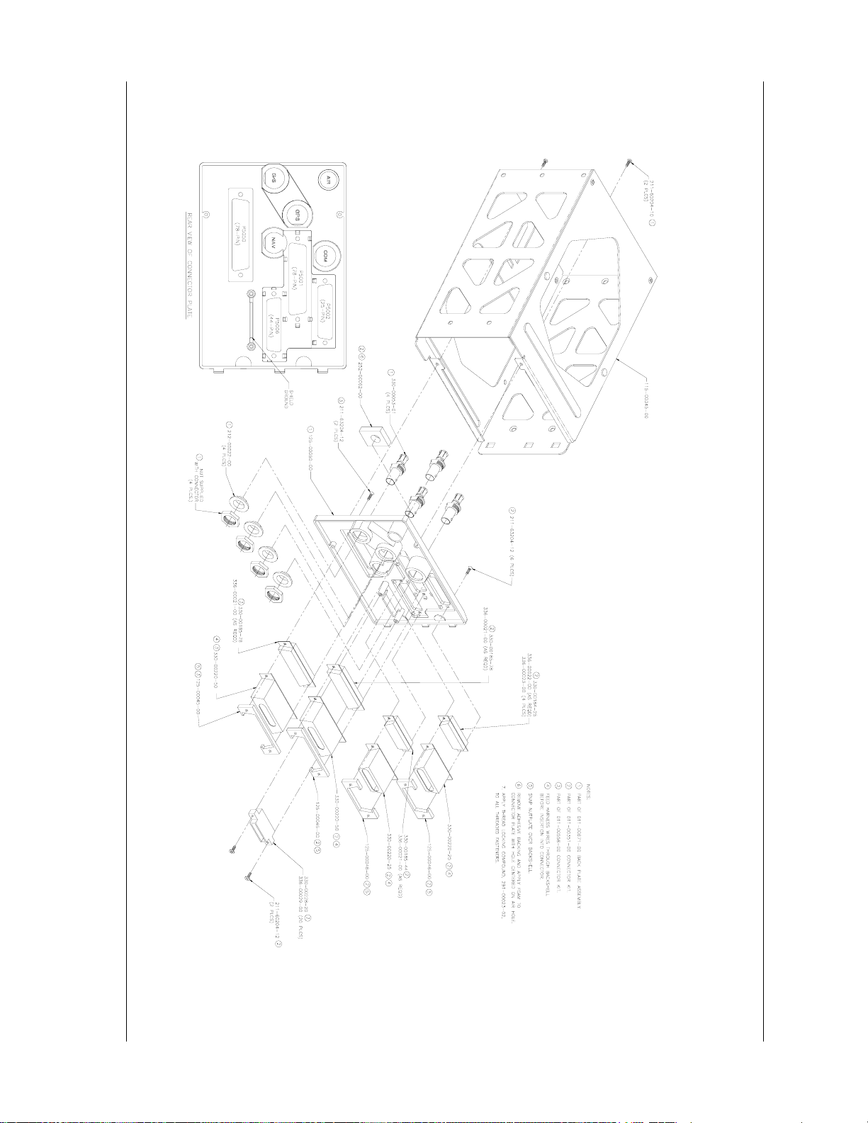
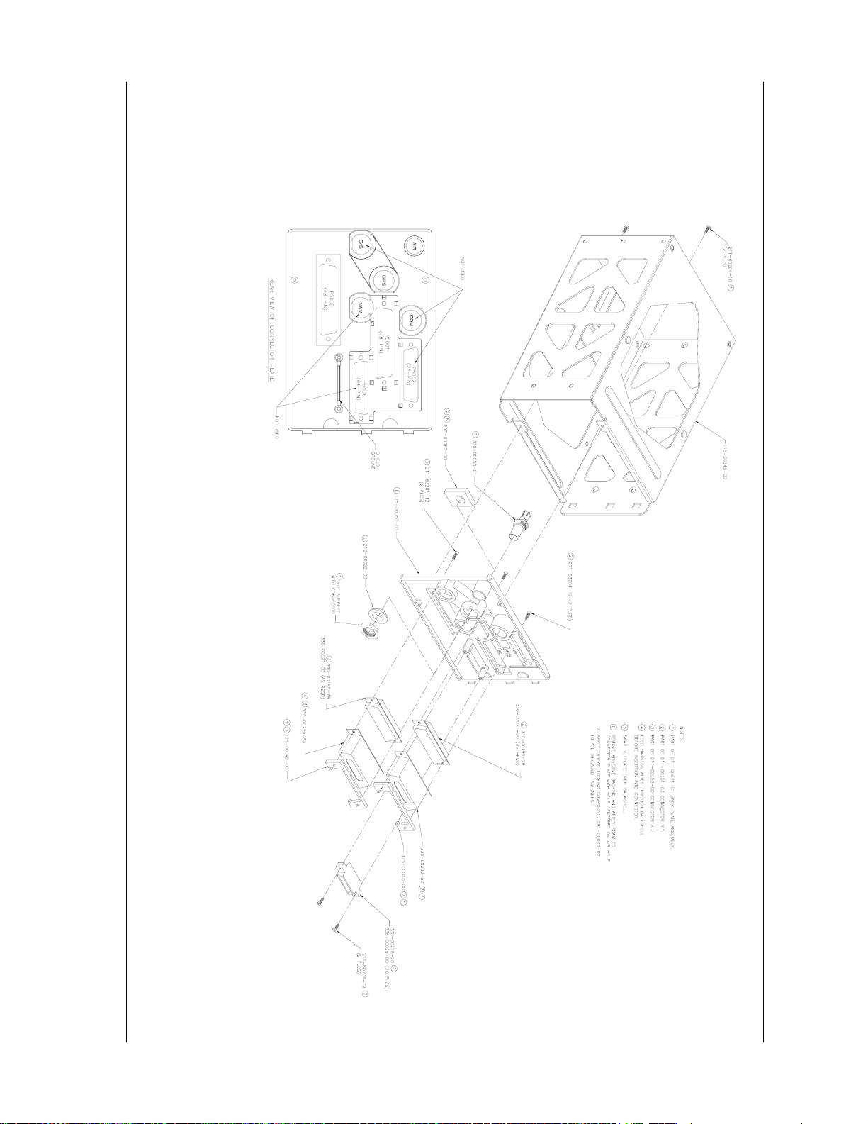
3.7 RACK INSTALLATION
1. The back plate of the rack may optionally be removed for ease of mounting in the aircraft
panel. To do so, remove the two #4-40 screws, tilt the back plate away from the tray, and then
slide the back plate to the side.
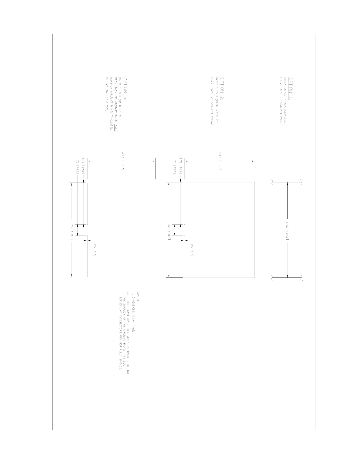
2. Figures 3-3 and 3-4, starting on page 3-9, shows outline dimensions for the aviation rack for
the various 500 Series units. Install the rack in a rectangular 6.320” x 4.600” hole (or gap
between units) in the instrument panel (refer to Figure 3-7, page 3-17). The lower-front lip of
the rack should be flush with, or extend slightly beyond, the finished aircraft panel.
CAUTION
If the front lip of the mounting rack is behind the surface of the aircraft panel, the 500 Series
unit connectors may not fully engage.
Make sure that no screw heads or other obstructions prevent the unit from fully engaging in the
rack (refer to the “Connector Engagement Test,” section 5.3.1, page 5-16). Exercise caution
when installing the rack into the instrument panel. The rack is designed to facilitate removal of
the 500 Series for use in Demo Mode outside the aircraft. Deformation of the rack may make it
difficult to install and remove the 500 Series unit.
500 SERIES INSTALLATION MANUAL Page 3-5
P/N 190-00181-02 Rev G

3. Install the rack in the aircraft panel using six #6-32 flat head screws and six self-locking nuts.
The screws are inserted from the inside through the holes in the sides of the rack.
4. If the back plate was previously removed (see step #1), replace the back plate by positioning
the tabs on the back plate in the slots of the left side of the rack (viewing it from the cockpit)
and attaching it by replacing the two #4-40 screws.
3.8 500 SERIES UNIT INSERTION AND REMOVAL
It may be necessary to insert the hex drive tool into the access hole and rotate the mechanism 90°
counterclockwise to insure correct position prior to placing the unit in the rack. The 500 Series unit is
installed in the rack by sliding it straight in until it stops, about 1 inch short of the final position. A 3/32”
hex drive tool is then inserted into the access hole at the bottom of the unit face. Rotate the hex tool
clockwise while pressing on the left side of the bezel until the unit is firmly seated in the rack.
To remove the unit from the rack, insert the hex drive tool into the access hole on the unit face and rotate
counterclockwise until the unit is forced out about 3/8” and can be freely pulled from the rack.
Be sure not to over tighten the unit into the rack. The application of hex drive tool torque exceeding
15 in•lbs can damage the locking mechanism.
3.9 COM ANTENNA INSTALLATION CHECK (GNS 530)
Check for insertion loss and VSWR (voltage standing wave ratio). VSWR should be checked with an inline type VSWR/wattmeter inserted in the coaxial transmission line between the transceiver and the
antenna. The VSWR should be inserted as close to the transceiver as possible. When rack and harness
buildup is performed in the shop, the coax termination may be provisioned by using a 6” inline BNC
connection. This would be an acceptable place to insert the VSWR. Any problem with the antenna
installation is most likely seen as high reflected power. A VSWR of 3:1 may result in up to a 50% loss in
transmit power.
Page 3-6 500 SERIES INSTALLATION MANUAL
Rev G P/N 190-00181-02
500 SERIES INSTALLATION MANUAL Page 3-7 (Page 3-8 blank)
P/N 190-00181-02 Rev G
3.10 GA 56 Antenna Installation Drawing
Figure 3-2. GA 56 Antenna Installation Drawing
500 SERIES INSTALLATION MANUAL Page 3-9 (Page 3-10 blank)
P/N 190-00181-02 Rev G
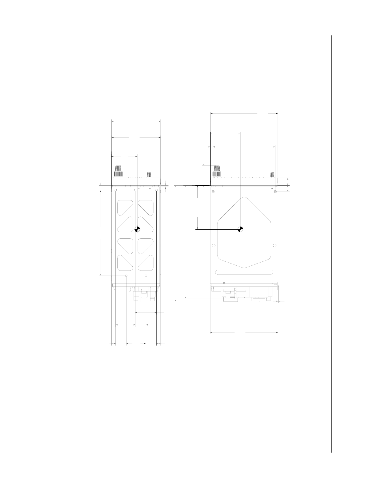
%).1%#6+10+0%.7&'54#&+110.;
8+&'1%#4&%100'%614-+69'+)*6ÄÄ.$5-)5
3.11 Mounting Rack Dimensions
=?
$'<'.
&+/2.'5
=?
61
=?
=?
=?
=?
=?
)2570+610.;9'+)*6.$5-)5
&+/'05+105+0%*OO
016'5
+056#..'&9+6*4#%-#0&%100'%61459'+)*6.$5-)5
=?
$'<'.
=?
=?
=?
=?
=?
=?
=?
=?
=?
=?
61&Ä57$564#+04'.+'(5
Figure 3-3. GNS 530 Mounting Rack Dimensions
&+/2.'5
61
=?
=?
=?
=?
&+/2.'5
61
=?
=?
61%1#:'5
=?
=?
4#%-
500 SERIES INSTALLATION MANUAL Page 3-11 (Page 3-12 blank)
P/N 190-00181-02 Rev G
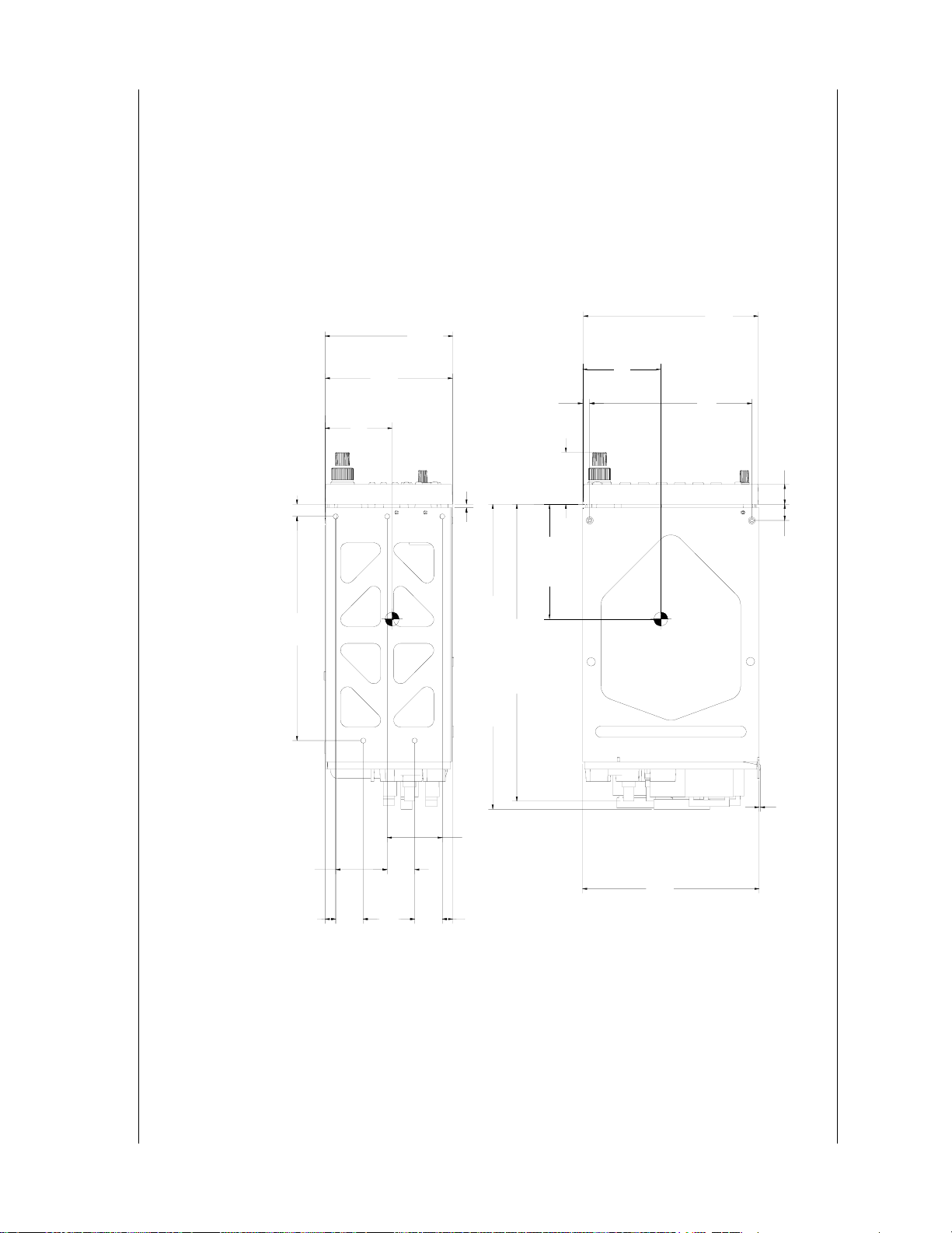
=?
$'<'.
&+/2.'5
=?
61
%).1%#6+10+0%.7&'54#&+110.;
)2570+610.;9'+)*6.$5-)5
&+/'05+105+0%*OO
016'5
8+&'1%#4&%100'%614-+69'+)*6ÄÄ.$5-)5
+056#..'&9+6*4#%-#0&%100'%61459'+)*6.$5-)5
=?
$'<'.
=?
=?
=?
=?
=?
=?
=?
=?
=?
=?
=?
Figure 3-4. GPS 500 Mounting Rack Dimensions
=?
=?
=?
=?
&+/2.'5
61
=?
=?
=?
=?
61&Ä57$564#+04'.+'(5
61%1#:'5
=?
=?
=?
4#%-
&+/2.'5
61
=?
500 SERIES INSTALLATION MANUAL Page 3-13 (Page 3-14 blank)
P/N 190-00181-02 Rev G
3.12 Mounting Rack Installation
Figure 3-5. GNS 530 Mounting Rack Installation
500 SERIES INSTALLATION MANUAL Page 3-15 (Page 3-16 blank)
P/N 190-00181-02 Rev G
Figure 3-6. GPS 500 Mounting Rack Installation
500 SERIES INSTALLATION MANUAL Page 3-17 (Page 3-18 blank)
P/N 190-00181-02 Rev G
3.13 Recommended Panel Cutout Dimensions
Figure 3-7. 500 Series Recommended Panel Cutout Dimensions