

Page 1

GPSMAP® 695/696
Portable Aviation Receiver
Owner’s Manual
Page 2

Page 3

OVERVIEW
GPS NAVIGATION
FLIGHT PLANNING
HAZARD AVOIDANCE
ADDITIONAL FEATURES
APPENDICES
INDEX
Page 4

Page 5

Copyright © 2008, 2012 Garmin Ltd. or its subsidiaries. All rights reserved.
This manual reflects the operation of System Software version 6.00 or later. Some differences
in operation may be observed when comparing the information in this manual to earlier or later
software versions.
Garmin International, Inc., 1200 East 151st Street, Olathe, Kansas 66062, U.S.A.
Tel: 913/397.8200 Fax: 913/397.8282
Garmin AT, Inc., 2345 Turner Road SE, Salem, OR 97302, U.S.A.
Tel: 503/391.3411 Fax 503/364.2138
Garmin (Europe) Ltd, Liberty House, Bulls Copse Road, Hounsdown Business Park,
Southampton, SO40 9RB, U.K.
Tel: 44/0870.8501241 Fax: 44/0870.8501251
Garmin Corporation, No. 68, Jangshu 2nd Road, Shijr, Taipei County, Taiwan
Tel: 886/02.2642.9199 Fax: 886/02.2642.9099
Web Site Address: www.garmin.com
Except as expressly provided herein, no part of this manual may be reproduced, copied, transmitted,
disseminated, downloaded or stored in any storage medium, for any purpose without the express
written permission of Garmin. Garmin hereby grants permission to download a single copy of this
manual and of any revision to this manual onto a hard drive or other electronic storage medium to
be viewed for personal use, provided that such electronic or printed copy of this manual or revision
must contain the complete text of this copyright notice and provided further that any unauthorized
commercial distribution of this manual or any revision hereto is strictly prohibited.
Garmin®,GPSMAP®, FliteCharts® and SafeTaxi® are registered trademarks of Garmin Ltd. or its
subsidiaries. These trademarks may not be used without the express permission of Garmin.
Jeppesen® is a registered trademark of Jeppesen, Inc.
NavData® is a registered trademark of Jeppesen, Inc.
AC-U-KWIK
SiriusXM Satellite Radio is provided by SiriusXM Satellite Radio, Inc.
SiriusXM Weather is provided by SiriusXM Satellite Radio, Inc.
®
is a registered trademark of Penton Business Media, Inc.
.
July, 2012 190-00919-00 Rev. F Printed in Taiwan.
Page 6

Warnings, Cautions & Notes
WARNING: When installing the GPSMAP® 695/696, place the unit so it does
not obstruct the field of view or interfere with operating controls.
WARNING: The indicators represented on the Panel are based on GPS-derived
data and may differ from the instruments in the aircraft.
WARNING: The GPSMAP 695/696 is intended only as an aid for VFR
navigation. Do not attempt to use this unit for any purpose requiring precise
measurement of direction, distance, location, or topography.
WARNING: Navigation and terrain separation must NOT be predicated upon
the use of the terrain function. The GPSMAP 695/696 Terrain Proximity feature
is NOT intended to be used as a primary reference for terrain avoidance
and does not relieve the pilot from the responsibility of being aware of
surroundings during flight. The Terrain Proximity feature is only to be used
as an aid for terrain avoidance and is not certified for use in applications
requiring a certified terrain awareness system. Terrain data is obtained from
third party sources. Garmin is not able to independently verify the accuracy
of the terrain data.
WARNING: The displayed minimum safe altitudes (MSAs) are only advisory
in nature and should not be relied upon as the sole source of obstacle and
terrain avoidance information. Always refer to current aeronautical charts
for appropriate minimum clearance altitudes.
WARNING: The altitude calculated by GPSMAP 695/696 GPS receiver is
geometric height above Mean Sea Level and could vary significantly from
the altitude displayed by pressure altimeters. GPS altitude should never be
used for vertical navigation.
WARNING: Do not use outdated database information. Databases used
in the GPSMAP 695/696 must be updated regularly in order to ensure that
the information remains current. Pilots using any outdated database do so
entirely at their own risk.
WARNING: Do not use basemap (land and water data) information for
primary navigation. Basemap data is intended only to supplement other
approved navigation data sources and should be considered as an aid to
enhance situational awareness.
Garmin GPSMAP 695/696 Owner’s Manual
190-00919-00 Rev. F
Page 7

Warnings, Cautions & Notes
WARNING: Do not rely solely upon the display of traffic information for
collision avoidance maneuvering. The traffic display does not provide collision avoidance resolution advisories and does not under any circumstances
or conditions relieve the pilot’s responsibility to see and avoid other aircraft.
WARNING: Do not rely solely upon the display of traffic information to
accurately depict all of the traffic within range of the aircraft. Due to lack
of equipment, poor signal reception, and/or inaccurate information from
aircraft or ground stations, traffic may be present that is not represented on
the display.
WARNING: Do not use data link weather information for maneuvering in,
near, or around areas of hazardous weather. Information contained with in
data link weather products may not accurately depict current weather conditions.
WARNING: Do not use the indicated data link weather product age to
determine the age of the weather information shown by the data link weather
product. Due to time delays inherent in gathering and processing weather
data for data link transmission, the weather information shown by the data
link weather product may be significantly older than the indicated weather
product age.
WARNING: For safety reasons, GPSMAP 695/696 operational procedures
must be learned on the ground.
WARNING: The United States government operates the Global Positioning
System and is solely responsible for its accuracy and maintenance. The GPS
system is subject to changes which could affect the accuracy and performance
of all GPS equipment. Portions of the Garmin GPSMAP 695/696 utilize GPS
as a precision electronic NAVigation AID (NAVAID). Therefore, as with all
NAVAIDs, information presented by the GPSMAP 695/696 can be misused
or misinterpreted and, therefore, become unsafe.
190-00919-00 Rev. F
Garmin GPSMAP 695/696 Owner’s Manual
Page 8

Warnings, Cautions & Notes
WARNING: To reduce the risk of unsafe operation, carefully review and
understand all aspects of the GPSMAP 695/696 User’s Manual documentation
and the Pilot’s Operating Handbook for the aircraft. Thoroughly practice basic
operation prior to actual use. During flight operations, carefully compare
indications from the GPSMAP 695/696 to all available navigation sources,
including the information from other NAVAIDs, visual sightings, charts, etc.
For safety purposes, always resolve any discrepancies before continuing
navigation.
WARNING: The illustrations in this guide are only examples. Never use the
GPSMAP 695/696 to attempt to penetrate a thunderstorm. Both the FAA
Advisory Circular, Subject: Thunderstorms, and the Aeronautical Information
Manual (AIM) recommend avoiding “by at least 20 miles any thunderstorm
identified as severe or giving an intense radar echo.”
CAUTION: The display uses a lens coated with a special anti-reflective coating
that is very sensitive to skin oils, waxes, and abrasive cleaners. CLEANERS
CONTAINING AMMONIA WILL HARM THE ANTI-REFLECTIVE COATING. It is
very important to clean the lens using a clean, lint-free cloth and an eyeglass
lens cleaner that is specified as safe for anti-reflective coatings.
CAUTION: The Garmin GPSMAP 695/696 does not contain any userserviceable parts. Repairs should only be made by an authorized Garmin
service center. Unauthorized repairs or modifications could void both the
warranty and the pilot’s authority to operate this device under FAA/FCC
regulations.
NOTE: The Garmin GPSMAP 695/696 has a very high degree of functional
integrity. However, the pilot must recognize that providing monitoring and/or
self-test capability for all conceivable system failures is not practical. Although
unlikely, it may be possible for erroneous operation to occur without a fault
indication shown by the GPSMAP 695/696. It is thus the responsibility of
the pilot to detect such an occurrence by means of cross-checking with all
redundant or correlated information available in the cockpit.
NOTE: All visual depictions contained within this document, including screen
images of the GPSMAP 695/696 display, are subject to change and may not
reflect the most current GPSMAP 695/696 and aviation databases. Depictions
of equipment may differ slightly from the actual equipment.
Garmin GPSMAP 695/696 Owner’s Manual
190-00919-00 Rev. F
Page 9

Warnings, Cautions & Notes
NOTE: This device complies with part 15 of the FCC Rules. Operation is
subject to the following two conditions: (1) this device may not cause harmful
interference, and (2) this device must accept any interference received,
including interference that may cause undesired operation.
NOTE: The data contained in the terrain and obstacle databases comes from
government agencies. Garmin accurately processes and cross-validates the
data, but does not guarantee the accuracy and completeness of the data.
NOTE: This product, its packaging, and its components contain chemicals
known to the State of California to cause cancer, birth defects, or reproductive
harm. This notice is being provided in accordance with California’s Proposition
65. If you have any questions or would like additional information, please
refer to our web site at www.garmin.com/prop65.
NOTE: Use of polarized eyewear may cause the display to appear dim or
blank.
NOTE: Do not rely solely upon data link services to provide Temporary Flight
Restriction TFR information. Always confirm TFR information through official
sources such as Flight Service Stations of Air Traffic Control.
NOTE: SiriusXM Weather is only available when the optional GXM 40 antenna
is installed.
190-00919-00 Rev. F
Garmin GPSMAP 695/696 Owner’s Manual
Page 10

Part Number Change Summary
190-00919-00 Initial release.
Rev Date Description
D November,
Production Release.
2008
E March,
2012
System Software Version 2.00 - 2.20 changes:
• Added separate leg and cumulative distance, ETE, and fuel fields to the
flight plan pages.
System Software Version 2.20-2.30 changes:
• Added indication of airport CTAF frequencies to WPT page.
System Software Version 2.70-2.80 changes:
• Added display of plain-language PIREP text.
• Added display of VOR radials when airway is highlighted.
• Added display of country when reviewing a user waypoint.
• Added sea surface temperature data.
• Added display of parachute jumping area.
System Software Version 2.90-3.00:
• Added daylight savings time information display on Airport Waypoint
page.
System Software Version 3.10-3.20 changes:
• FlightCharts are no longer disabled after fade date.
• Added ability to import/export flight data via datacard.
• Added ablility to highlight multiple weather objects using map cursor.
• Added XM page menu option for selecting a specific channel number.
• Added nearest airport page softkeys for toggling on/off private airports
and heliports.
• Added TIS traffic data status indicator to the Map Page.
System Software Version 3.30-4.00 changes:
• Added user-created checklists.
• Added support to export user waypoints and track logs to SD card.
• Added support for ChartView and geo-referenced FlightCharts.
System Software Version 4.20-4.30 changes:
• Added SiriusXM warning text.
• Added menu options to WPT page for viewing departure and
destination airports.
• Added displaced runway threshold distance on airport review page.
• Added suggested indicated altitude on E6B page.
RR-10
Garmin GPSMAP 695/696 Owner’s Manual
190-00919-00 Rev. F
Page 11

Rev Date Description
E March,
2012
System Software Version 4.40-4.50 changes:
• Added AC-U-KWIK airport data support.
System Software Version 4.70-4.80 changes:
• Added display setup option to show/hide aircraft position on maps and
charts.
System Software Version 4.80-4.90 changes:
• Added configurable data fields to display current climb gradient in
percent or altitude gain per nautical mile.
• Added runway number labels to runway extension lines on map.
• Added Map Setup page items for adjusting visibility of water labels,
park and land cover areas, runway numbers, and runway extension
lines.
• Added separate control for speed and distance units.
• Added custom waypoint symbols support.
• Changed screenshot utility to be activated when Menu key is pressed
and held.
• Changed XTK data fields display to more closely resemble G3X
presentation.
Other changes:
• Changed XM to SiriusXM throughout.
• Added TRAFFIC Softkey to Map Page Softkeys.
• Added AOPA/DIRECTORY Softkey update info.
• Added Terrain Page Softkeys.
• Added Info Page Softkey.
• Added Active Flight Plan Page Softkeys.
• Added Flight Plan List Page Softkeys.
• Added VNAV Page Softkeys.
• Added Nearest Page Softkeys.
• Updated AIRMETS and SIGMETS.
• Added PIREP info.
• Added Turbulence Forecast info.
• Added Icing Forecast info.
• Updated Chartview and FliteChart info.
• Updated AOPA Airport Directory to just Airport Directory where
applicable.
• Updated System Messages.
• Updated Data Field Options
• Updated database information.
190-00919-00 Rev. F
Garmin GPSMAP 695/696 Owner’s Manual
RR-11
Page 12

Rev Date Description
F July, 2012 System Software Version 4.90-5.00 changes:
• Correct Disclaimer page database expiration date information
• Correct missing ‘Mark’ waypoint operation (695 units only)
System Software Version 5.00-6.00 changes:
• Added GDL 39 support
RR-12
Garmin GPSMAP 695/696 Owner’s Manual
190-00919-00 Rev. F
Page 13

Table of Contents
SECTION 1 OVERVIEW ..................................................................................... 1
1.1 Unit Overview ............................................................................................................1
Battery Care and Charging ................................................................................................... 2
Turning the Unit On/Off ........................................................................................................ 4
GPS Receiver Status ............................................................................................................. 6
1.2 GPSMAP 695/696 Controls ........................................................................................8
1.3 Accessing System Functionality .............................................................................10
Menus ............................................................................................................................... 10
Data Entry .......................................................................................................................... 11
Pages ................................................................................................................................. 13
Main Page Softkeys ............................................................................................................ 18
Flight Planning Softkeys...................................................................................................... 23
Nearest Page Softkeys ........................................................................................................ 24
1.4 System Settings ......................................................................................................25
Display ............................................................................................................................... 26
Sound ................................................................................................................................ 28
Units .................................................................................................................................. 29
Date & Time ....................................................................................................................... 30
Position .............................................................................................................................. 30
Interface ............................................................................................................................ 31
Alarms ............................................................................................................................... 31
Power ................................................................................................................................ 32
Setting Airport Criteria ........................................................................................................ 33
Utilities .............................................................................................................................. 34
SECTION 2 GPS NAVIGATION ....................................................................... 35
2.1 Introduction .............................................................................................................35
Data Bar Fields ................................................................................................................... 36
Compass Arc ...................................................................................................................... 38
2.2 Panel .........................................................................................................................40
Changing the CDI Scale ...................................................................................................... 41
Setting the Bug Indicator .................................................................................................... 42
Manually Setting a Course .................................................................................................. 42
2.3 Vertical Navigation (VNAV) ....................................................................................43
Using the VNAV Feature ..................................................................................................... 44
2.4 Using Map Displays .................................................................................................46
Map Orientation................................................................................................................. 47
Map Range ........................................................................................................................ 48
Map Panning ..................................................................................................................... 49
Measuring Bearing and Distance ........................................................................................ 51
Topography ........................................................................................................................ 52
Satellite View ..................................................................................................................... 53
Map Symbols ..................................................................................................................... 54
190-00919-00 Rev. F
Garmin GPSMAP 695/696 Owner’s Manual
i
Page 14

Table of Contents
Airports & NAVAIDs............................................................................................................ 55
Cities & Roads ................................................................................................................... 56
Airspace ............................................................................................................................. 57
Airways .............................................................................................................................. 57
2.5 Waypoints ................................................................................................................60
Frequencies ........................................................................................................................ 63
Nearest Information ........................................................................................................... 64
Weather Information .......................................................................................................... 66
Intersections ...................................................................................................................... 68
NDBs ..................................................................................................................... 68
VORs ................................................................................................................................. 69
User Waypoints .................................................................................................................. 70
2.6 Airspace....................................................................................................................74
Airspace Alert Messages ..................................................................................................... 75
Smart Airspace
™ ..................................................................................................................................................................................................... 75
2.7 Direct-to Navigation ...............................................................................................76
SECTION 3 FLIGHT PLANNING ...................................................................... 79
3.1 Introduction .............................................................................................................79
Data Fields ......................................................................................................................... 79
3.2 Flight Plan Creation ................................................................................................81
Adding Waypoints to an Existing Flight Plan ........................................................................ 83
Graphical Flight Planning.................................................................................................... 85
3.3 Flight Plan Storage .................................................................................................88
3.4 Flight Plan Activation .............................................................................................89
Editing Speed and Fuel Flow ............................................................................................... 90
Copying Flight Plans ........................................................................................................... 92
Deleting Flight Plans .......................................................................................................... 92
Inverting a Flight Plan ........................................................................................................ 94
Importing/Exporting Flight Plans ......................................................................................... 95
3.5 Approaches ..............................................................................................................96
Selecting an Approach ........................................................................................................ 97
Activating Vectors-to-Final ................................................................................................ 100
3.6 Trip Planning ..........................................................................................................101
SECTION 4 HAZARD AVOIDANCE ................................................................ 103
4.1 Weather Information ............................................................................................103
SiriusXM Weather (696 only) ............................................................................................ 104
Data Link weather (FIS-B) ................................................................................................. 124
4.2 Terrain ....................................................................................................................142
Terrain Information ........................................................................................................... 143
Obstacle Information ........................................................................................................ 143
Terrain and Obstacle Color Code....................................................................................... 144
ii
Garmin GPSMAP 695/696 Owner’s Manual
190-00919-00 Rev. F
Page 15

Table of Contents
Terrain Settings ................................................................................................................ 144
Terrain Alerts .................................................................................................................... 147
4.3 Traffic Information ...............................................................................................149
Traffic Information Service (TIS-A) ..................................................................................... 150
Data Link Traffic (GDL 39) ................................................................................................. 154
SECTION 5 ADDITIONAL FEATURES ............................................................ 165
5.1 SafeTaxi ..................................................................................................................165
SafeTaxi Cycle Number and Revision ................................................................................. 167
5.2 ChartView (Optional) ............................................................................................167
Aircraft Symbol................................................................................................................. 169
Chart Range ..................................................................................................................... 170
Jeppesen Database-published NOTAMs ............................................................................ 170
5.3 FliteCharts
Chart Range ..................................................................................................................... 172
Aircraft Symbol................................................................................................................. 174
FliteCharts Cycle Number and Expiration Date .................................................................. 175
5.4 Airport Directory Data ..........................................................................................176
5.5 SiriusXM Radio Entertainment (GPSMAP 696) ....................................................178
Activating SiriusXM Satellite Radio Services ....................................................................... 178
Using SiriusXM Radio ........................................................................................................ 179
5.6 Electronic Checklists .............................................................................................184
5.7 Flight Data Logging ..............................................................................................185
® .............................................................................................................................................................................................171
SECTION 6 APPENDICES ............................................................................. 187
Messages, Alerts & Data Field Options ......................................................................187
System Messages ............................................................................................................. 187
Airspace Messages ........................................................................................................... 189
Aural Alerts ...................................................................................................................... 189
Data Field Options ........................................................................................................... 190
Abnormal Operation ....................................................................................................193
Resetting the Unit ............................................................................................................ 193
Loss of GPS Position ......................................................................................................... 193
Hazard Display with Loss of GPS Position .......................................................................... 194
SD Card Use and Databases ........................................................................................195
SD Card Use ..................................................................................................................... 195
GPSMAP 695/696 Databases ........................................................................................... 196
Updating GPSMAP 695/696 Databases ............................................................................ 200
Exporting Track Logs and User Waypoints .......................................................................... 203
Importing/Exporting Flight Plans ....................................................................................... 203
Installation & Interfacing Information ......................................................................205
Connecting the Power/Data Cable .................................................................................... 205
Connecting to a Garmin VHF Comm Radio ........................................................................206
190-00919-00 Rev. F
Garmin GPSMAP 695/696 Owner’s Manual
iii
Page 16

Table of Contents
Connecting to a Computer ............................................................................................... 207
Information about USB Drivers ......................................................................................... 208
Using xImage for Customized Waypoint Symbols ............................................................... 208
Connecting the GXM 40 Antenna (GPSMAP 696) .............................................................208
Connecting to a GTX 330 Mode S Transponder ................................................................. 209
Connecting to a GDL 39 ................................................................................................... 209
Interfacing ....................................................................................................................... 212
Using an external GPS Antenna (Optional) ........................................................................ 215
General TIS-A Information ..........................................................................................217
TIS-A vs. TAS/TCAS ........................................................................................................... 217
TIS-A Limitations .............................................................................................................. 218
Utilities ..........................................................................................................................221
Flight Log ......................................................................................................................... 221
Track Log ......................................................................................................................... 223
Heading Line .................................................................................................................... 226
Aircraft Profile .................................................................................................................. 230
Weight & Balance ............................................................................................................ 232
EPE Circle ........................................................................................................................ 233
Proximity Waypoints ......................................................................................................... 234
Display Symbols ...........................................................................................................237
VFR Symbols .................................................................................................................... 237
IFR Symbols ..................................................................................................................... 238
Airspace Symbols ............................................................................................................. 240
Map Datum and Location Formats .............................................................................243
Map Datums .................................................................................................................... 243
Location Formats .............................................................................................................. 243
Glossary ........................................................................................................................245
License Agreement and Warranty ..............................................................................251
Contact Garmin................................................................................................................ 251
Software License Agreement ............................................................................................. 251
Limited Warranty .............................................................................................................. 251
AOPA Airport Directory Notice .......................................................................................... 252
AC-U-KWIK LICENSE AGREEMENT .................................................................................... 252
Weather Data Warranty .................................................................................................... 253
SiriusXM Satellite Radio Service Agreement ....................................................................... 254
FCC Compliance............................................................................................................... 254
Industry Canada Compliance ............................................................................................ 254
Index ..........................................................................................................................Index-1
iv
Garmin GPSMAP 695/696 Owner’s Manual
190-00919-00 Rev. F
Page 17

Overview
SECTION 1 OVERVIEW
1.1 UNIT OVERVIEW
The GPSMAP 695/696 presents GPS-derived analog flight instrumentation,
position, navigation, and hazard avoidance information to the pilot using a 7” Wide
VGA (800x480) color display.
7” WVGA (800x480)
Color Display
Power Button
SD Card Slot
External GPS Antenna
Connector
Audio (Headphones/Line Out)
USB Connector
Overview GPS Navigation Flight Planning Hazard Avoidance Additional Features Appendices Index
190-00919-00 Rev. F
Backlit Keypad
Unit Overview
Garmin GPSMAP 695/696 Owner’s Manual
External Power/Serial Port
Connector
Battery Pack
1
Page 18

Overview
BATTERY CARE AND CHARGING
BATTERY WARNINGS
OverviewGPS NavigationFlight PlanningHazard AvoidanceAdditional FeaturesAppendicesIndex
If these guidelines are not followed, the internal Nickel Metal Hydride battery may
experience a shortened life span or may present a risk of damage to the GPS unit, fire,
chemical burn, electrolyte leak, and/or injury.
•Contactyourlocalwastedisposaldepartmenttoproperlyrecycle/disposeofthe
unit/battery.
•Donotleavetheunitexposedtoaheatsourceorinahightemperaturelocation,
such as in the sun in an unattended aircraft on a hot day. To prevent damage,
remove the unit from the aircraft or store it out of direct sunlight.
•Donotdisassemble,puncture,damage,orincineratetheunit/battery.
•Whenstoringtheunitforalimitedlengthoftime(lessthan30days),storewithin
the following temperature range: -68° to 122°F (-20° to 50°C). When storing the
unit for an extended time, store within the following temperature range: -68° to
86°F (-20° to 30°C).
•Donotoperatetheunitoutsideofthefollowingtemperaturerange:-68°to140°F
(-20° to 60°C).
•Keeptheusedbatteryawayfromchildren.
AdditionAl User-replAceAble bAttery WArnings
•Donotuseasharpobjecttoremovethebattery.
•Donotrechargethebatteryoutoftheunit.
•OnlyreplacewithaGarminNickelMetalHydridebatterypack.Usinganother
battery presents a risk of fire or explosion. To purchase a replacement battery, see
your Garmin dealer or the Garmin Web site.
AdditionAl non-User-replAceAble bAttery WArnings
•Donotremoveorattempttoremovethenon-user-replaceablebattery.
•When disposing ofthe unit, take it to a professionalservice,suchas a waste
electronics treatment facility, to have the battery removed and recycled.
2
Garmin GPSMAP 695/696 Owner’s Manual
190-00919-00 Rev. F
Page 19

Overview
INSERTING/REMOVING THE BATTERY PACK
Battery Locks (In)
Inserting the Battery Pack
Battery Locks (Out)
CHARGING THE BATTERY PACK
Plug the unit into a 12-Volt or 24-Volt connector to charge. The unit can be used
while it is charging. Charge the unit within the following temperature range
104°F (0° to 40°C).
Charging the unit’s battery pack:
1)
Align the notches on the unit with the vehicle power cable plug.
2)
Push the plug into the external power connector until fully seated.
3)
Plug the power cable into the aircraft power outlet (cigarette lighter
receptacle).
4)
Route the power cable so that it does not interfere with aircraft operation.
: 32° to
Overview GPS Navigation Flight Planning Hazard Avoidance Additional Features Appendices Index
The unit begins charging as soon as external power is applied. When the unit in
Charge Mode it reduces the draw on the aircraft’s battery.
Using chArge mode
NOTE: While in Charge Mode, the unit draws a current from the aircraft. To
avoid discharging the aircraft’s battery, disconnect the external power cable
from the unit when not in use for several days.
Applying external power to the GPSMAP 695/696 automatically turns on the unit for
full operation. If the battery is present and needs to be charged, the external power
source charges the battery while the unit is in use.
190-00919-00 Rev. F
Garmin GPSMAP 695/696 Owner’s Manual
3
Page 20

Overview
If you do not want to use the unit, but you would like to charge the battery, you can
put the unit into Charge Mode. Connect the unit to an external power supply. Press
and hold the POWER Button. Instead of completely turning off, the unit now goes
OverviewGPS NavigationFlight PlanningHazard AvoidanceAdditional FeaturesAppendicesIndex
into Charge Mode.
TURNING THE UNIT ON/OFF
Press and hold the POWER Button to turn the unit on or off.
NOTE: If the display appears dark or dim, adjust the display backlighting as
necessary upon power up. The GPSMAP 695/696 retains the backlighting
settings between power cycles. Backlighting may have been set to a level
not suitable for the current ambient lighting. For more information on display
backlighting see section 1.4 (System Settings).
The power button can be used to quickly set the backlight intensity. A momentary
press of the power button (after the unit is powered on) will display a window showing
the current backlight setting. From this window the backlight setting can be adjusted
with the joystick knob, or a second momentary press of the power button changes the
backlight level to full bright (10).
Adjusting Backlighting on Power up
The first time the unit is turned on, the receiver must collect satellite data and
establish its present location. To ensure proper initialization, the GPSMAP 695/696 is
shipped from the factory in AutoLocate mode, which allows the receiver to “find itself”
anywhere in the world.
4
Garmin GPSMAP 695/696 Owner’s Manual
190-00919-00 Rev. F
Page 21

Overview
During initialization, current database information is displayed. Database information
includes valid operating dates, cycle number, and database type. When this information
has been reviewed for currency (to ensure that no databases have expired), the pilot
is prompted to continue.
Press the ENT Key to acknowledge this information.
Database Initialization
After acknowledgement of the database information, the pilot is prompted to
acknowledge a data link weather advisory.
Overview GPS Navigation Flight Planning Hazard Avoidance Additional Features Appendices Index
Data link Weather Advisory
Press the ENT Key to acknowledge this information.
190-00919-00 Rev. F
Garmin GPSMAP 695/696 Owner’s Manual
5
Page 22

Overview
GPS RECEIVER STATUS
The receiver status field on the INFO Page displays one of the following conditions:
OverviewGPS NavigationFlight PlanningHazard AvoidanceAdditional FeaturesAppendicesIndex
•Autolocate—Receiver is looking for any satellite whose almanac has been
collected, which can take up to 5 minutes
•SearchingtheSky—Receiverislookingforsatellites
•AcquiringSatellites—Receiver is lookingforand collectingdatafrom satellites
visible at its last known or initialized location, but has not acquired a fix
•2D GPS Location—At least three satellites have been acquired and a two-
dimensional location fix has been calculated. “2D Differential” appears when
you are receiving DGPS corrections in 2D mode
•3D GPS Location—At least four satellites have been acquired and a three-
dimensional fix has been calculated. “3D Differential” appears when you are
receiving DGPS corrections in 3D mode
•LostSatelliteReception—thereceiverisnolongertrackingenoughsatellitesfora
2D or 3D fix
Constellation
Diagram
PRN Number
45° Above
Horizon
Horizon
6
GPS Status (Info Page)
Garmin GPSMAP 695/696 Owner’s Manual
Receiver Status
Signal
Strength Bar
PRN Number
190-00919-00 Rev. F
Page 23

Overview
ACQUIRING SATELLITES
Overview GPS Navigation Flight Planning Hazard Avoidance Additional Features Appendices Index
When the receiver is in the process of acquiring enough satellite signals for navigation,
the receiver uses satellite orbital data (collected continuously from the satellites) and last
known position to determine the satellites that should be in view. ‘Acquiring Satellites’
is indicated as the solution until a sufficient number of satellites have been acquired for
computing a solution.
When the receiver is in the process of acquiring a 3D differential GPS solution, ‘3D GPS
Location’ is indicated as the solution until the 3D differential fix has finished acquisition.
SATELLITE INFORMATION
Satellites currently in view are shown at their respective positions on a satellite
constellation diagram. The outer circle of the constellation diagram represents the horizon,
the inner circle represents 45° above the horizon, and the center point shows the position
directly overhead. Each satellite is represented by a square containing the Pseudo-Random
Noise (PRN) number (i.e., satellite identification number).
The INFO Page can be helpful in troubleshooting weak (or missing) signal levels due to
poor satellite coverage or installation problems. As the GPS receiver locks onto satellites, a
signal strength bar is displayed for each satellite in view, with the appropriate satellite PRN
number (01-32 or 33-64 for WAAS) below each bar. The progress of satellite acquisition is
shown in three stages, as indicated by signal bar appearance:
-Nobar—Receiverislookingfortheindicatedsatellite
-Graybar—Receiverhascollectedthenecessarydataandthesatellitesignalcan
be used
-Greenbar—SatelliteisbeingusedfortheGPSsolution
190-00919-00 Rev. F
Garmin GPSMAP 695/696 Owner’s Manual
7
Page 24

Overview
1.2 GPSMAP 695/696 CONTROLS
The GPSMAP 695/696 controls have been designed to simplify operation of the system
OverviewGPS NavigationFlight PlanningHazard AvoidanceAdditional FeaturesAppendicesIndex
and minimize workload and the time required to access sophisticated functionality.
1
2
3
4
5
6
7
8
9
10
Controls
1
Power
Button
2
RNG Key Press to increase or decrease the viewing range of the map
3
FMS
Joystick
Press and hold to turn the unit on or off
With the unit on, press to adjust the backlight and volume
Press the FMS Joystick to toggle input focus between user
interaction with the current page and the page navigation bar
Turn the FMS Joystick clockwise to access a dropdown menu
Turn the FMS Joystick to change the selected value within the
highlighted field
Move the FMS Joystick to highlight fields or move the map pointer
when interacting with the page
8
Garmin GPSMAP 695/696 Owner’s Manual
190-00919-00 Rev. F
Page 25

Overview
4
ENT Key Press to confirm menu selection or data entry
Press to acknowledge messages
Press and hold to mark a waypoint
5
CLR Key Press to cancel an entry, revert to the previous value in a data entry
field or remove menus
Press and hold to return to the default page
6
MENU Key Press once to view the Page Menu
Press twice to view the Main Menu
Press a third time to clear the Main Menu
7
FPL Key Press to display the Flight Plan Page
Press a second time to remove the Flight Plan Page
8
Direct-To
Key
9
NRST Key Press to display the Nearest Page for viewing the nearest airports,
Press to activate the Direct-To function, enter a destination
waypoint and establish a direct course to the selected destination
intersections, NDBs, VORs, waypoints, frequencies, and airspaces
10
Softkey
Press to select the softkey shown above the bezel key on the unit
Selection
Keys
Overview GPS Navigation Flight Planning Hazard Avoidance Additional Features Appendices Index
190-00919-00 Rev. F
Garmin GPSMAP 695/696 Owner’s Manual
9
Page 26

Overview
1.3 ACCESSING SYSTEM FUNCTIONALITY
MENUS
OverviewGPS NavigationFlight PlanningHazard AvoidanceAdditional FeaturesAppendicesIndex
The GPSMAP 695/696 has a dedicated MENU Key that when pressed once displays
a context-sensitive list of options for the page (Page Menu), and when pressed twice
displays the Main Menu.
The Page Menu allows the user to access additional features or make settings
changes which specifically relate to the currently displayed window/page. Menus
display ‘No Options’ when there are no options for the window/page selected.
Navigating the Page Menu:
1)
Press the MENU Key once to display the Page Menu.
2)
Turn or move the FMS Joystick to scroll through a list of available options
(a scroll bar always appears to the right of the window/box when the
option list is longer than the window/box).
3)
Press the ENT Key to select the desired option.
4)
Press the FMS Joystick, the CLR Key, or the MENU Key twice to remove the
menu and cancel the operation.
Page Menu (No Options)
Navigating the Main Menu:
1)
Press the MENU Key twice to display the Main Menu.
2)
Turn or move the FMS Joystick to scroll through a list of available options
(a scroll bar always appears to the right of the window/box when the
option list is longer than the window/box).
3)
Press the ENT Key to select the desired option.
4)
Press the FMS Joystick, the CLR Key, the EXIT Softkey, or the MENU Key to
remove the menu and cancel the operation.
10
Garmin GPSMAP 695/696 Owner’s Manual
Terrain (TER) Page Menu
190-00919-00 Rev. F
Page 27

Main Menu
Overview
Overview GPS Navigation Flight Planning Hazard Avoidance Additional Features Appendices Index
DATA ENTRY
The FMS Joystick can be used for directly entering alphanumeric data into the
GPSMAP 695/696. In some instances, such as when entering an identifier, the
GPSMAP 695/696 tries to predict the desired identifier based on the characters being
entered. In this case, if the desired identifier appears, use the ENT Key to confirm the
entry without entering the rest of the identifier manually. This can save the pilot from
having to enter all the characters of the identifier.
Besides character-by-character data entry, the system also provides a shortcut
for entering waypoint identifiers. When the cursor is on a field awaiting entry of a
waypoint identifier, turning the FMS Joystick counter-clockwise accesses a menu with
three different lists of identifiers for quick selections: recent waypoints (RECENT WPTS),
nearest airports (NRST APTS), and flight plan waypoints (FPL WPTS). The GPSMAP
695/696 automatically fills in the identifier, facility and city fields with the information
for the selected waypoint.
190-00919-00 Rev. F
Garmin GPSMAP 695/696 Owner’s Manual
11
Page 28

Overview
Using the FMS Joystick to enter data:
1)
Press the FMS Joystick to activate the cursor.
2)
OverviewGPS NavigationFlight PlanningHazard AvoidanceAdditional FeaturesAppendicesIndex
Move the FMS Joystick to highlight the desired field.
3)
Begin entering data.
a)
To quickly enter a waypoint identifier, turn the FMS Joystick counterclockwise to display a list of recent waypoints (RECENT WPTS), nearest
airports (NRST APTS), or flight plan waypoints (FPL WPTS).
b)
Move the FMS Joystick to highlight the desired waypoint from the list
and press the ENT Key.
Waypoint Entry (Waypoint Page)
12
Or
:
a)
Turn the FMS Joystick to select a character for the first placeholder.
Data Entry
Turning the FMS Joystick clockwise scrolls through the alphabet (where
appropriate) toward the letter Z, starting in the middle at K (US only), and
the digits zero through nine. Turning the FMS Joystick counter-clockwise
scrolls in the opposite direction.
b)
Use the FMS Joystick to move the cursor to the next placeholder in the
field.
c)
Repeat, turning the FMS Joystick to select a character and using the
FMS Joystick to move the cursor, until the fields are complete.
d)
Press the ENT Key to confirm entry.
4)
Press the FMS Joystick or the CLR Key to cancel data entry (the field reverts
back to its previous information).
Garmin GPSMAP 695/696 Owner’s Manual
190-00919-00 Rev. F
Page 29

Overview
PAGES
NOTE:
the GPSMAP 696.
The Weather (WX) Page
and (XM) Audio Page are only available with
Overview GPS Navigation Flight Planning Hazard Avoidance Additional Features Appendices Index
The pages are linked together in a series that you can cycle through using the
FMS Joystick. A page navigation bar is displayed in the lower portion of each page,
directly above the softkey bar. The right side of the page navigation bar shows a list
of abbreviated names for each of the main pages, and the left side shows the name
of the active page.
Press the FMS Joystick to toggle input focus between the page navigation bar and
interaction with the current page (i.e., turning the cursor on/off).
Selected Page
Active Page Title
Input Focus on Navigation Bar
(Page Cursor Off)
Input Focus on Current Page
(Page Cursor On)
There are up to six main pages that can be navigated using the FMS Joystick.
Selecting a Main Page using the FMS Joystick:
1)
If necessary press the FMS Joystick to begin interaction with the Navigation
Bar.
2)
Turn the
FMS Joystick
until the desired page is selected (MAP, WPT, WX,
TER, XM, INFO).
190-00919-00 Rev. F
Garmin GPSMAP 695/696 Owner’s Manual
13
Page 30

Overview
OverviewGPS NavigationFlight PlanningHazard AvoidanceAdditional FeaturesAppendicesIndex
•
Main Pages
Map Page (MAP)
Traffic Page (TRF)
Waypoint Page (WPT) XM Audio Page (XM) (optional)
Weather Page (WX) (optional) Info Page (INFO)
Terrain Page (TER)
14
Garmin GPSMAP 695/696 Owner’s Manual
190-00919-00 Rev. F
Page 31

Overview
FPL AND NRST PAGES
There are also several pages which are selected first by pressing the FPL Key or
NRST Key.
Selecting the FPL or NRST Pages:
1)
Press the FPL or NRST Key.
2)
Turn the FMS Joystick until the desired page is selected.
3)
Press the EXIT Softkey to return to the Main Pages.
The Nearest Pages contain the following information.
•APT (Airport)—identier,bearing,distance,length of the longest runway, and
common traffic advisory (CTAF) or tower frequency.
•VRP (Visual Reporting Point) (Atlantic Unit Only)—identier, bearing, and
distance.
•WX (Airport Weather)—identier,bearing,distance,METARtext(GPSMAP696
only), and ATIS, AWOS, or ASOS frequency.
•VOR (VHF Omnidirectional Radio Beacon)—identier, facility type (symbol),
bearing, distance, and frequency.
•NDB (Non Directional Beacons)—identier, facility, type (symbol), bearing,
distance, and frequency.
Overview GPS Navigation Flight Planning Hazard Avoidance Additional Features Appendices Index
•INT (Intersection)—identier,bearing,anddistance.
•USR (User Waypoints)—name,bearing,anddistance.
•CTY (City)—name,bearing,anddistance.
•ATC (Air Route Traffic Control Center)—bearing,distance,andfrequency.
•FSS (Flight Service Station)—name, bearing, distance, frequency, and VOR (if
applicable).
•ASPC (Airspace)—name,timetoentry(whenapplicable),andstatus.
190-00919-00 Rev. F
Garmin GPSMAP 695/696 Owner’s Manual
15
Page 32

Overview
•
OverviewGPS NavigationFlight PlanningHazard AvoidanceAdditional FeaturesAppendicesIndex
Nearest Pages (NRST)
Nearest Airports (APT) Nearest User Waypoints (USR)
Visual Reporting Point (VRP) (Atlantic Unit) Nearest Cities (CTY)
Nearest Airport Weather (WX) Nearest ARTCC (ATC)
Nearest VORs (VOR) Nearest FSS (FSS)
Nearest NDBs (NDB) Nearest Airspace (ASPC)
Nearest Intersections (INT)
16
Garmin GPSMAP 695/696 Owner’s Manual
190-00919-00 Rev. F
Page 33

Overview
•Flight Planning Pages (FPL)
Active Flight Plan (ACTV) Vertical Navigation (VNAV)
Flight Plan List (LIST)
Overview GPS Navigation Flight Planning Hazard Avoidance Additional Features Appendices Index
MAIN MENU PAGES
The Main Menu pages are accessed by pressing the Menu Key twice and using the
FMS Joystick to navigate the menu.
Selecting the main menu pages:
1)
Press the MENU Key twice. The Main Menu is displayed.
2)
Turn or move the FMS Joystick to highlight the desired menu option and
press the ENT Key.
190-00919-00 Rev. F
Garmin GPSMAP 695/696 Owner’s Manual
17
Page 34

Overview
SYSTEM SETUP PAGES
The System Setup pages are accessed from the Main Menu.
OverviewGPS NavigationFlight PlanningHazard AvoidanceAdditional FeaturesAppendicesIndex
Selecting the system setup pages:
1)
Press the MENU Key twice. The Main Menu is displayed.
2)
Turn or move the FMS Joystick to highlight ‘System Setup...’ and press the
ENT Key. The System Setup Menu is displayed.
3)
Turn or move the FMS Joystick to highlight the desired menu option and
press the ENT Key.
MAIN PAGE SOFTKEYS
The softkeys are located along the bottom of the display. The softkeys shown depend
on the softkey level or page being displayed. The bezel keys below the softkeys can be
used to select the appropriate softkey. When a softkey is selected, its color undergoes
a momentary change to black text on blue background then automatically switches to
black text on gray background and remains this way until it is turned off, at which time
it reverts to white text on black background. When a softkey function is disabled, the
softkey label is subdued (dimmed).
Softkey
On
Bezel Mounted
Softkeys (Press)
18
Softkeys (WPT Page)
Garmin GPSMAP 695/696 Owner’s Manual
Softkey Names
(Displayed)
190-00919-00 Rev. F
Page 35

Overview
MAP
VFR MAP
BACK
IFR MAP TOPO
BACK
Press the BACK Softkey to
return to the top-level softkeys.
SAT VIEW
HIGH AWYLOW AWYIFR MAPVFR MAP
MAP PAGE SOFTKEYS
MAP
TERRAIN
WEATHER
MAP Enables second-level Map Page softkeys
TERRAIN Displays/removes terrain awareness information
WEATHER Displays/removes weather information
TRAFFIC Displays/removes traffic information
PANEL Displays/removes the panel
TRAFFIC PANEL
Overview GPS Navigation Flight Planning Hazard Avoidance Additional Features Appendices Index
VFR MAP Softkey selected
IFR MAP Displays IFR map information and softkeys
TOPO Displays/removes topographical terrain shading
SAT VIEW Displays/removes satellite imagery (above 20nm scale)
BACK Returns to top-level softkeys
IFR MAP Softkey selected
VFR MAP Displays VFR map information and softkeys
LOW AWY Low Altitude (Victor) Airways displayed
HIGH AWY High Altitude Airways (Jet Routes) displayed
BACK Returns to top-level softkeys
190-00919-00 Rev. F
Garmin GPSMAP 695/696 Owner’s Manual
19
Page 36

Overview
WAYPOINT PAGE SOFTKEYS
OverviewGPS NavigationFlight PlanningHazard AvoidanceAdditional FeaturesAppendicesIndex
INFO
CHART AOPA WEATHER
(DIRECTORY)
Waypoint (WPT) Page Softkeys
INFO Displays waypoint information
CHART Displays chart data (i.e., FliteCharts® or ChartView)
AOPA or DIRECTORY Displays airport directory information
WEATHER Displays METAR and TAF text (optional)
WEATHER PAGE SOFTKEYS (OPTIONAL)
INFOANIMATESETUP
PAN MAP
PAN MAP Activates the map pointer for panning the map
SETUP Select the weather source (XM or FIS-B).
ANIMATE Animates NEXRAD Radar and Satellite Mosaic weather
INFO Displays XM Information
LEGEND Displays weather legends
LEGEND
TERRAIN PAGE SOFTKEYS
Terrain (TER) Page Softkeys
SETTINGS Displays the Terrain Setup Page
DISABLE Toggles terrain alerts on/off.
20
Garmin GPSMAP 695/696 Owner’s Manual
DISABLESETTINGS
190-00919-00 Rev. F
Page 37

VOL +
BACK VOL -
MUTE
VOLUME
Press the BACK Softkey to
return to the top-level softkeys.
INFO
CHANNEL
VOLUME CATEGORY
PRESETS
PAN MAP
ANIMATE
LEGEND
INFO
CHART
APPRCH
AOPA WEATHER
MAP
VFR MAP
BACK
IFR MAP TOPO
BACK
Press the BACK Softkey to
return to the top-level softkeys.
SAT VIEW
HIGH AWYLOW AWYIFR MAPVFR MAP
MAP
TERRAIN
WEATHER
TRAFFIC PAGE SOFTKEYS (OPTIONAL GDL 39)
INFO
ALT MODE
Overview
Overview GPS Navigation Flight Planning Hazard Avoidance Additional Features Appendices Index
DISABLEFLT ID
INFO Select to view Data Link and Weather info
INFO
STATIONS
SETUP
BACKUNRESTABOVEBELOW NORMAL
EXIT
FLT ID Displays FLT ID information.
ALT MODE Select to set altitude mode.
DISABLE Temporally disables traffic alerts
ALT MODE Softkey selected
BELOW Displays non-threat and proximity traffic from 2700 feet
NORMAL Displays non-threat and proximity traffic from 2700 feet
ABOVE Displays non-threat and proximity traffic from 9000 feet
UNREST (Unrestricted): All traffic is displayed from 9900 feet
above the aircraft to 9000 feet below the aircraft.
Typically used during descent phase of flight.
above the aircraft to 2700 feet below the aircraft.
Typically used during enroute phase of flight.
above the aircraft to 2700 feet above the aircraft.
Typically used during enroute phase of flight.
above and 9900 feet below the aircraft.
INFO Softkey selected
Stations Displays ADS-B ground station(s) information.
SETUP Select to set pressure altitude sensor on or off in the
GDL 39.
EXIT Returns to the Traffic Page.
190-00919-00 Rev. F
Garmin GPSMAP 695/696 Owner’s Manual
21
Page 38

Overview
INFO
CHANNEL
VOLUME
CATEGORY
FAVORITE
SiriUsXM AUDIO PAGE SOFTKEYS (OPTIONAL)
OverviewGPS NavigationFlight PlanningHazard AvoidanceAdditional FeaturesAppendicesIndex
INFO Displays SiriusXM Information
CATEGORY Highlights the Category field
CHANNEL Highlights the Channels field
FAVORITE Displays a list of favorite channels
VOLUME Enables second-level VOLUME softkeys
Press and hold to toggle Mute on/off.
Press the BACK Softkey to
return to the top-level softkeys.
VOL +
BACK VOL -
MUTE
VOLUME
VOL - Decreases SiriusXM audio volume
VOL + Increases SiriusXM audio volume
MUTE Toggles SiriusXM audio on/off
BACK Returns to top-level softkeys
INFO PAGE SOFTKEY
MESSAGES Displays system status messages
22
Garmin GPSMAP 695/696 Owner’s Manual
MESSAGES
190-00919-00 Rev. F
Page 39

Overview
FLIGHT PLANNING SOFTKEYS
ACTIVE FLIGHT PLAN PAGE SOFTKEYS
USE MAP
USE MAP Activates the Map Pointer
SEL APPR Displays the Select Approach Window
EXIT Exits the Flight Plan Pages
FLIGHT PLAN LIST PAGE SOFTKEYS
ACTIVATE
ACTIVATE Displays the ‘Activate Flight Plan?’ Window
NEW Displays the ‘New Flight Plan’ Window
IMPORT Displays the available flight plans to import from the SD
EXPORT Exports the selected flight plan
EXIT Exits the Flight Plan Pages
SEL APPR EXIT
NEW EXITIMPORT EXPORT
Card
Overview GPS Navigation Flight Planning Hazard Avoidance Additional Features Appendices Index
VERTICAL NAVIGATION (VNAV) PAGE SOFTKEYS
CAPTURE Captures/cancels VNAV profile
EXIT Exits the Flight Plan Pages
190-00919-00 Rev. F
Garmin GPSMAP 695/696 Owner’s Manual
EXITCAPTURE
23
Page 40

Overview
NEAREST PAGE SOFTKEYS
NEAREST AIRPORT PAGE SOFTKEYS
OverviewGPS NavigationFlight PlanningHazard AvoidanceAdditional FeaturesAppendicesIndex
PRIVATE EXITHELIPORT
PRIVATE Displays/removes the nearest private airports
HELIPORT Displays/removes the nearest heliports
EXIT Exits the Nearest Pages
Various softkeys revert to the previous level after 45 seconds of inactivity (e.g.,
PAN MAP, VOLUME, etc), other softkeys require manual de-selection (e.g., TERRAIN,
WEATHER, PANEL, etc.).
24
Garmin GPSMAP 695/696 Owner’s Manual
190-00919-00 Rev. F
Page 41

Overview
1.4 SYSTEM SETTINGS
Overview GPS Navigation Flight Planning Hazard Avoidance Additional Features Appendices Index
The System Setup Menu in the Main Menu allows management of the following
system parameters:
•Display
•Sound
•Units
•Date&Time
•Position
•Interface
•Alarms
•Power
System Setup Menu
Restoring system setting defaults:
1)
Press the MENU Key twice to display the Main Menu.
2)
Turn or move the FMS Joystick to highlight ‘System Setup...’ and press the
ENT Key.
190-00919-00 Rev. F
Garmin GPSMAP 695/696 Owner’s Manual
25
Page 42

Overview
3)
Turn or move the FMS Joystick to highlight the desired menu option
(Display, Sound, Units, Date & Time, Position, Interface, Alarms, or Power),
and press the ENT Key.
OverviewGPS NavigationFlight PlanningHazard AvoidanceAdditional FeaturesAppendicesIndex
4)
Press the MENU Key.
5)
With the ‘Restore Default’ highlighted press the ENT Key.
DISPLAY
BACKLIGHTING
NOTE: The GPSMAP 695/696 retains the backlighting settings between
power cycles. Backlighting may have been set to a level not suitable for the
current ambient lighting.
Restore Default Window
The large color display can be set to various brightness levels to allow for easy
viewing in full sunlight or dimmed for night viewing. The power button can be used to
quickly set the backlight intensity. By momentarily pressing the power button (when
the unit is powered on) a window appears showing the current backlight setting. From
this window the backlight setting can be adjusted with the joystick knob, or a second
momentary press of the power button changes the backlight level to full bright (10).
This provides a display which can be read under most lighting conditions. Once this
method of changing the backlight to full bright has been used, the previously selected
value is lost and the new backlight level is (10) and will remain at (10) until it is
manually adjusted.
Adjusting display backlighting:
1)
Press the MENU Key twice to display the Main Menu.
2)
Turn or move the FMS Joystick to highlight ‘System Setup...’ and press the
ENT Key.
3)
With ‘Display’ highlighted press the ENT Key.
26
Garmin GPSMAP 695/696 Owner’s Manual
190-00919-00 Rev. F
Page 43

Overview
4)
With the ‘Backlight Intensity’ field highlighted adjust the intensity by
turning the FMS Joystick.
5)
Press the FMS Joystick, the CLR Key, the EXIT Softkey or the MENU Key to
remove the menu.
Display Setup Page
Or
:
1)
Momentarily Press the POWER Button.
2)
With the ‘Backlight’ field highlighted adjust the intensity by turning the
FMS Joystick.
Or
: Momentarily Press the POWER Button again to automatically set the
backlight intensity to full bright (10). The display will remain at full bright
until manually adjusted.
3)
With ‘Done’ highlighted press the ENT Key.
4)
Press the FMS Joystick, or the CLR Key to remove the menu.
Overview GPS Navigation Flight Planning Hazard Avoidance Additional Features Appendices Index
BACKLIGHT TIMEOUT
After a specified period of inactivity the backlight will turn off to save battery power.
Adjusting backlight timeout:
1)
Press the MENU Key twice to display the Main Menu.
2)
Turn or move the FMS Joystick to highlight ‘System Setup...’ and press the
ENT Key.
3)
With ‘Display’ highlighted press the ENT Key.
190-00919-00 Rev. F
Garmin GPSMAP 695/696 Owner’s Manual
27
Page 44

Overview
4)
With the ‘Backlight Timeout’ field highlighted adjust the time by turning the
FMS Joystick.
5)
OverviewGPS NavigationFlight PlanningHazard AvoidanceAdditional FeaturesAppendicesIndex
Press the FMS Joystick, the CLR Key, the EXIT Softkey or the MENU Key to
remove the menu.
SCREENSHOTS
Enabling/disabling Screenshots:
1)
Press the MENU Key twice to display the Main Menu.
2)
Turn or move the FMS Joystick to highlight ‘System Setup...’ and press the
ENT Key.
3)
Turn or move the FMS Joystick to highlight ‘Display’, and press the ENT
Key.
4)
Move the FMS Joystick to highlight the Screenshot field.
5)
Turn the FMS Joystick to highlight ‘Enabled’ or ‘Disabled’.
Saving a Screenshot:
1)
With screenshots enabled (see above), navigate to the desired screen.
2)
Press and hold the MENU Key until the screen flashes indicating the
screenshot was saved to the SD Card.
AIRCRAFT POSITION ON MAP/CHARTS
Displaying/removing the aircraft position on maps/charts:
1)
Press the MENU Key twice to display the Main Menu.
2)
Turn or move the FMS Joystick to highlight ‘System Setup...’ and press the
ENT Key.
3)
With ‘Display’ highlighted press the ENT Key.
4)
With the ‘Aircraft Position’ field highlighted, turn the FMS Joystick to select
‘Hide’ or ‘Show’ and press the ENT Key.
SOUND
Adjusting sound:
1)
Press the MENU Key twice to display the Main Menu.
2)
Turn or move the FMS Joystick to highlight ‘System Setup...’ and press the
ENT Key.
3)
Turn or move the FMS Joystick to highlight ‘Sound’ and press the ENT Key.
28
Garmin GPSMAP 695/696 Owner’s Manual
190-00919-00 Rev. F
Page 45

4)
With the desired option highlighted, adjust the sound by turning the FMS
Joystick.
5)
Press the FMS Joystick, the CLR Key, the EXIT Softkey or the MENU Key to
remove the menu.
Sound Setup Page
UNITS
Changing display unit settings:
1)
Press the MENU Key twice to display the Main Menu.
2)
Turn or move the FMS Joystick to highlight ‘System Setup...’ and press the
ENT Key.
3)
Turn or move the FMS Joystick to highlight ‘Units’ and press the ENT Key.
4)
With the desired unit highlighted adjust the unit measurement by turning
the FMS Joystick.
5)
Press the FMS Joystick, the CLR Key, the EXIT Softkey or the MENU Key to
remove the menu.
Overview
Overview GPS Navigation Flight Planning Hazard Avoidance Additional Features Appendices Index
190-00919-00 Rev. F
Units Setup Page
Garmin GPSMAP 695/696 Owner’s Manual
29
Page 46

Overview
DATE & TIME
Changing date & time settings:
OverviewGPS NavigationFlight PlanningHazard AvoidanceAdditional FeaturesAppendicesIndex
1)
Press the MENU Key twice to display the Main Menu.
2)
Turn or move the FMS Joystick to highlight ‘System Setup...’ and press the
ENT Key.
3)
Turn or move the FMS Joystick to highlight ‘Date & Time’ and press the
ENT Key.
4)
Move the FMS Joystick to highlight the desired field, and select the desired
option by turning the FMS Joystick.
5)
Press the FMS Joystick, the CLR Key, the EXIT Softkey or the MENU Key to
remove the menu.
Date & Time Setup Page
POSITION
NOTE:
Changing position settings:
1)
2)
3)
4)
5)
30
Refer to Appendix H for more information on Map Datums and Location
Formats.
Press the MENU Key twice to display the Main Menu.
Turn or move the FMS Joystick to highlight ‘System Setup...’ and press the
ENT Key.
Turn or move the FMS Joystick to highlight ‘Position’ and press the ENT
Key.
Move the FMS Joystick to highlight the desired field, and select the desired
option by turning the FMS Joystick.
Press the FMS Joystick, the CLR Key, the EXIT Softkey or the MENU Key to
remove the menu.
Garmin GPSMAP 695/696 Owner’s Manual
190-00919-00 Rev. F
Page 47

INTERFACE
Overview
Overview GPS Navigation Flight Planning Hazard Avoidance Additional Features Appendices Index
Position Setup Page
NOTE:
Refer to Appendix D for more information on Interfacing.
Changing interface settings:
1)
Press the MENU Key twice to display the Main Menu.
2)
Turn or move the FMS Joystick to highlight ‘System Setup...’ and press the
ENT Key.
3)
Turn or move the FMS Joystick to highlight ‘Interface’ and press the ENT
Key.
4)
Turn the FMS Joystick to select the desired ‘Serial Data Format’.
5)
Press the FMS Joystick, the CLR Key, the EXIT Softkey or the MENU Key to
remove the menu.
ALARMS
The Alarms Page allows the pilot to turn airspace alarms On/Off, set an Altitude
Buffer, Arrival Alarm, Next Waypoint Alarm, Proximity Alarm, and Fuel Tank Reminder
Alarm.
Changing alarm settings:
1)
Press the MENU Key twice to display the Main Menu.
2)
Turn or move the FMS Joystick to highlight ‘System Setup...’, and press the
ENT Key.
3)
Turn or move the FMS Joystick to highlight ‘Alarms’ and press the ENT Key.
4)
Move the FMS Joystick to highlight the desired field, and select the desired
option by turning the FMS Joystick.
5)
Press the FMS Joystick, the CLR Key, the EXIT Softkey or the MENU Key to
remove the menu.
190-00919-00 Rev. F
Garmin GPSMAP 695/696 Owner’s Manual
31
Page 48

Overview
OverviewGPS NavigationFlight PlanningHazard AvoidanceAdditional FeaturesAppendicesIndex
Alarms Page
POWER
Turning the power loss warning on/off:
1)
Press the MENU Key twice to display the Main Menu.
2)
Turn or move the FMS Joystick to highlight ‘System Setup...’, and press the
ENT Key.
3)
Turn or move the FMS Joystick to highlight ‘Power’ and press the ENT Key.
4)
Turn the FMS Joystick to select ‘On’ or ‘Off’, and press the ENT Key.
32
Garmin GPSMAP 695/696 Owner’s Manual
190-00919-00 Rev. F
Page 49

Overview
SETTING AIRPORT CRITERIA
The Page Menu on the Nearest Airports Page allows the pilot to filter out airports
that do not meet a defined criteria. Specific surface types and runway lengths can be
defined, as well as the option to include private airports and/or heliports.
RunwaySurface—allowsyoutosetcriteriaforthetypeofsurfaceontherunway:
•
Any—showsanyrunway,regardlessofsurfacetype,includingwaterlanding
facilities.
•
HardOnly—showsonlyrunwayswithaconcrete,asphalt,orsimilarsealed
surface.
•
HardorSoft—showsallrunwaysexceptwaterlandingfacilities.
•
WaterOnly—showsonlywaterlandingfacilities.
MinimumRunwayLength—allowsthepilottoenteraspeciclengthfortheshortest
runway allowed.
Entering airport criteria:
1)
Press the NRST Key.
2)
Turn the FMS Joystick to select the Nearest Airports Page.
3)
Press the MENU Key to display the Page Menu.
4)
Turn or move the FMS Joystick to select ‘Set Airport Criteria’, and then
press the ENT Key. The Airport Criteria Window appears with the current
settings.
Overview GPS Navigation Flight Planning Hazard Avoidance Additional Features Appendices Index
5)
Move the FMS Joystick to highlight the desired field and turn the FMS
Joystick to select the desired option from the menu. Press the ENT Key if
necessary to highlight the next field.
190-00919-00 Rev. F
Nearest Airports Page Menu
Garmin GPSMAP 695/696 Owner’s Manual
33
Page 50

Overview
OverviewGPS NavigationFlight PlanningHazard AvoidanceAdditional FeaturesAppendicesIndex
6)
With ‘Done’ highlighted press the ENT Key.
To restore airport criteria defaults:
1)
Press the NRST Key.
2)
Turn the FMS Joystick to select the Nearest Airports Page.
3)
Press the MENU Key to display the Page Menu.
4)
Turn or move the FMS Joystick to select ‘Set Airport Criteria’, and then
press the ENT Key. A window appears with the current settings.
5)
Press the MENU Key.
6)
With ‘Restore Default’ highlighted press the ENT Key.
Airport Criteria Window
UTILITIES
Refer to Appendix F for information on Flight Log, Track Log, E6B, Aircraft Profile,
and Weight & Balance.
34
Garmin GPSMAP 695/696 Owner’s Manual
190-00919-00 Rev. F
Page 51

GPS Navigation
SECTION 2 GPS NAVIGATION
Overview GPS Navigation Flight Planning Hazard Avoidance Additional Features Appendices Index
2.1 INTRODUCTION
The Navigation Map displays aviation data (e.g., airports, VORs, airways, airspaces),
geographic data (e.g., cities, lakes, highways, borders), and topographic data (map
shading indicating elevation). The Navigation Map can be oriented three different
ways: North Up (NORTH UP), Track Up (TRK UP), or Desired Track Up (DTK UP).
An aircraft icon is placed on the Navigation Map at the location corresponding
to the calculated present position. The aircraft position and the flight plan legs are
accurately based on GPS calculations. The basemap upon which these are placed are
from a source with less resolution, therefore the relative position of the aircraft to map
features is not exact. The leg of the active flight plan currently being flown is shown as
a magenta line on the navigation map. The other legs are shown in white.
The Direct-to Window, the Flight Plan Pages, and the Nearest Airports Pages can be
displayed by pressing the corresponding key.
The page layout of the Map, Terrain, and Info Pages can be independently configured
by the user.
190-00919-00 Rev. F
Page Layout
Map Only + +
Map with Panel +
4 Data Bar Fields + + +
8 Data Bar Fields + + +
12 Data Bar Fields + + +
6 Data Bar Fields and HSI + +
Page Layout
Garmin GPSMAP 695/696 Owner’s Manual
Map
Page
Terrain
Page
Info
Page
35
Page 52
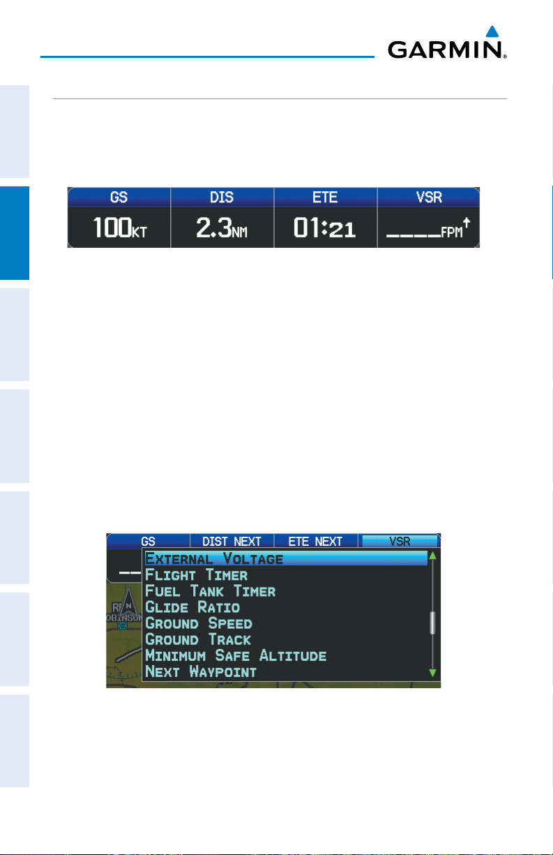
GPS Navigation
DATA BAR FIELDS
The number and content of the data bar fields on the Map, Terrain, and Info Pages
are independently configured by the user. For each page that supports data bar fields
OverviewGPS NavigationFlight PlanningHazard AvoidanceAdditional FeaturesAppendicesIndex
the user may choose 0, 4, 8, 12, or 6 and the HSI (if available).
Data Bar Fields
By default, the Navigation Map Data Bar Fields are set to display ground speed (GS),
distance (NEXT), estimated time enroute (ETE NEXT), and vertical speed required (VSR).
These four data fields can be changed to display any of the Data Bar Field Options.
Changing the information shown in the data bar fields:
1)
From the Map Page, Terrain Page, or the Info Page press the MENU Key.
2)
Turn or move the FMS Joystick to highlight ‘Change Data Fields’ and press
the ENT Key.
3)
Move the FMS Joystick to highlight the desired data field.
4)
Turn the FMS Joystick to access the list of options, then turn or move the
FMS Joystick to highlight the desired option and press the ENT Key.
36
Data Bar Field Selection
Garmin GPSMAP 695/696 Owner’s Manual
190-00919-00 Rev. F
Page 53

DATA BAR FIELD OPTIONS
•Accuracy
GPS Navigation
•ExternalVoltage(EXTVOLTS)
Overview GPS Navigation Flight Planning Hazard Avoidance Additional Features Appendices Index
•Altitude
•Battery
•Bearing(BRG)
•Climb Gradient (Alt Per NM)
(CLIMB/NM)
•ClimbGradient(PERCENT)
•CoursetoSteer(CTS)
•CrosstrackError(XTK)
•DesiredTrack(DTK)
•Distance(DESTINATION)
•Distance(NEXT)
•EnRouteSafeAltitude(ESA)
•Estimated Time En route
(DESTINATION) (ETE DEST)
•Estimated Time Enroute (NEXT)
(ETE NEXT)
•Estimated Time of Arrival
(DESTINATION) (ETA DEST)
•Estimated Time of Arrival (NEXT)
(ETA NEXT)
•FlightTimer(FLTTIMER)
•FuelTankTimer(FUELTIMER)
•GlideRatio(GLIDERATIO)
•GroundSpeed(GS)
•GroundTrack(TRK)
•MinimumSafeAltitude(MSA)
•NextWaypoint(NEXTWPT)
•Sunrise
•Sunset
•Time(UTC)
•TimeofDay(Local)(TIME)
•VerticalSpeed(VS)
•VerticalSpeedRequired(VSR)
•Weather(Altimeter)(WXALTIM)
•Weather(DewPoint)(WXDEWPT)
•Weather (Relative Humidity) (WX
HUMIDITY)
•Weather(Temperature)(WXTEMP)
•Weather(Wind)(WXWIND)
•Estimated Time to VNAV (VNAV
Time)
190-00919-00 Rev. F
Garmin GPSMAP 695/696 Owner’s Manual
37
Page 54

GPS Navigation
Changing page layout:
1)
From the Map Page, Terrain Page, or the Info Page press the MENU Key.
2)
Turn or move the FMS Joystick to highlight ‘Select Page Layout’ and press
OverviewGPS NavigationFlight PlanningHazard AvoidanceAdditional FeaturesAppendicesIndex
the ENT Key.
3)
Move the FMS Joystick to highlight the desired page layout option, and
press the ENT Key.
Page Layout Window (Map Page)
COMPASS ARC
NOTE:
A compass arc appears by default on the Map Page. The route line represents
the course and the magenta bug indicator (similar to the bug indicator on the HSI)
can be set to ‘Bearing’ (default), ‘Course to Steer’, a specific heading reference (‘User
Selected’), or ‘Off’.
38
The compass arc is not available in ‘North Up’ map orientation.
Garmin GPSMAP 695/696 Owner’s Manual
190-00919-00 Rev. F
Page 55

GPS Navigation
Magenta Bug Indicator
Compass Arc
Route Line
Compass Arc (Map Page)
Removing the Compass Arc from the Map Page:
1)
With the Map Page displayed, press the MENU Key.
2)
Turn or move the FMS Joystick to highlight ‘Set Up Map’ and press the
ENT Key.
3)
Turn the FMS Joystick to highlight the ‘General’ Menu.
4)
Move the FMS Joystick to highlight the ‘Compass Arc’ field.
5)
Turn the FMS Joystick to access the ‘On/Off’ drop down list.
6)
Turn or move the FMS Joystick to highlight ‘Off’, and press the ENT Key.
Overview GPS Navigation Flight Planning Hazard Avoidance Additional Features Appendices Index
190-00919-00 Rev. F
Garmin GPSMAP 695/696 Owner’s Manual
39
Page 56

GPS Navigation
2.2 PANEL
The panel shows GPS-derived data in a graphical format. Keep in mind the differences
OverviewGPS NavigationFlight PlanningHazard AvoidanceAdditional FeaturesAppendicesIndex
between the GPS-derived panel and mechanical instruments, as mechanical panel
instruments use sensors that provide information different from that derived using
GPS.
HSI
Ground Speed
Turn Rate Indicator
Estimated Time Enroute
Panel (Map Page)
- Next Waypoint
-Distance
Altitude
Vertical Speed
CDI Scale
The Panel shows a graphic Horizontal Situation Indicator (HSI) surrounded by
additional indicators.
The graphic HSI depicts the course to the destination or the next waypoint in a flight
plan, current ground track, off course error, and a To/From indication. The rotating
compass indicates your current ground track at the top of the page.
The course pointer and course deviation needle indicate the course and whether you
are on the course. The Bug Indicator can be set to ‘Bearing’ (default), ‘Course to Steer’,
a specific heading reference (‘User Selected’), or ‘Off’.
Bearing is the compass direction from the present position to a destination waypoint.
Course to Steer is the recommended direction to steer in order to reduce cross-track
error and return to the course line.
The Course Deviation Indicator, or needle, indicates how far off course, left or right,
based on its placement along the course deviation scale.
40
Garmin GPSMAP 695/696 Owner’s Manual
190-00919-00 Rev. F
Page 57

GPS Navigation
The course deviation scale setting is adjustable for Auto, ±0.25, 1.25 or 5.0 (nautical
mile, statute mile, or kilometer) full-scale deflection. The course deviation scale appears
on the lower right corner of the HSI. The default setting is Auto, which uses three
factors to determine the distance from the center of the CDI to full left or right limits:
•CDI scale = 1.25 - within 30 nm of any airport in the active route.
•CDI scale = 0.25 - on an approach leg or within 2 nm of the FAF or MAP.
•CDI scale = 5.0 - if the previous two conditions do not exist.
Displaying the panel on the map page:
From the Map Page press the PANEL Softkey.
Or:
1)
From the Map Page press the MENU Key to display the Map Page Menu.
2)
Turn or move the FMS Joystick to highlight ‘Select Page Layout’ and press
the ENT Key.
3)
Turn or move the FMS Joystick to highlight ‘Map with Panel’ and press the
ENT Key.
CHANGING THE CDI SCALE
Overview GPS Navigation Flight Planning Hazard Avoidance Additional Features Appendices Index
The CDI scale can be set from the Map Page Menu.
Changing the CDI scale:
1)
From the Map Page with the Panel, HSI, or Compass Arc displayed, press
the MENU Key to display the Map Page Menu
2)
Turn or move the FMS Joystick to highlight ‘Set CDI Scale’, and press the
ENT Key. The ‘Set CDI Scale’ Menu appears.
3)
Turn or move the FMS Joystick to highlight the desired menu option, and
press the ENT Key.
Map Page Menu Set CDI Scale Menu
190-00919-00 Rev. F
Garmin GPSMAP 695/696 Owner’s Manual
41
Page 58

GPS Navigation
SETTING THE BUG INDICATOR
The Bug Indicator can be set from the Map Page Menu.
OverviewGPS NavigationFlight PlanningHazard AvoidanceAdditional FeaturesAppendicesIndex
Setting the Bug Indicator:
1)
From the Map Page with the Panel, HSI, or Compass Arc displayed, press
the MENU Key to display the Map Page Menu.
2)
Turn or move the FMS Joystick to highlight ‘Set Bug Indicator’, and press
the ENT Key. The ‘Set Bug Indicator’ Menu appears.
3)
Turn or move the FMS Joystick to highlight the desired menu option, and
press the ENT Key. For the ‘User Selected’ option, turn the FMS Joystick to
select the desired heading reference, and press the ENT Key.
Map Page Menu Set Bug Indicator Menu
MANUALLY SETTING A COURSE
Use the ‘Set OBS and Hold’ option to manually set your course to the destination.
Manually setting a course to the destination waypoint:
1)
From the Map Page with the Panel, HSI, or Compass Arc displayed, press
the MENU Key to display the Map Page Menu.
2)
Turn or move the FMS Joystick to highlight ‘Set OBS and Hold’, and press
the ENT Key.
3)
Turn the FMS Joystick to select the desired course to the destination, and
press the ENT Key.
42
Garmin GPSMAP 695/696 Owner’s Manual
190-00919-00 Rev. F
Page 59

GPS Navigation
Map Page Menu Set OBS Window
Returning to automatic sequencing of route waypoints:
1)
From the Map Page after manually setting a course, press the MENU Key to
display the Map Page Menu
2)
Turn or move the FMS Joystick to highlight ‘Release Hold’, and press the
ENT Key.
2.3 VERTICAL NAVIGATION (VNAV)
The Vertical Navigation Page provides settings for the vertical navigation feature.
These settings create a three-dimensional profile from the present location and altitude
to a final (target) altitude at a specified location.
Overview GPS Navigation Flight Planning Hazard Avoidance Additional Features Appendices Index
When the VNAV profile is defined, the pilot is informed of the progress by message
alerts. The teal bar on the HSI (when displayed) shows the VNAV profile.
The Vertical Navigation feature is only available when navigating a Direct To or flight
plan, and the ground speed is greater than 35 knots.
The “Approaching VNAV Profile” message appears one minute prior to the initial
descent point. The descent angle locks to prevent changes in speed from altering the
profile. The VNAV feature does not take into account any changes in groundspeed that
occur during the transition from level flight to descent or climb.
At 500 ft above the target altitude, the “Approaching Target Altitude” message
appears, the ‘Estimated Time To VNAV’ goes blank, and the VNAV indicator disappears
from the HSI.
190-00919-00 Rev. F
Garmin GPSMAP 695/696 Owner’s Manual
43
Page 60

GPS Navigation
VNAV Profile
Glide Ratio to Target
Distance to Target
Distance to Profile
Target Altitude
Airport
OverviewGPS NavigationFlight PlanningHazard AvoidanceAdditional FeaturesAppendicesIndex
CAUTION: The GPSMAP 695/696 is a VFR navigation tool and should not
be used to perform instrument approaches.
CAUTION: VNAV is only a VFR navigation aid and is not intended for
instrument approaches.
Visual Representation of VNAV
USING THE VNAV FEATURE
Use the VNAV (Vertical Navigation) feature to ensure the aircraft is at the proper
altitude. The VNAV Indicator appears on the HSI (when displayed) as a horizontal teal
bar. A message appears when approaching the VNAV Profile. When the bar is in the
vertical center of the HSI, the aircraft is at the proper altitude for the VNAV Profile.
Configuring a VNAV profile:
1)
While navigating a flight plan or direct-to, press the FPL Key.
2)
Turn the FMS Joystick to select the Vertical Navigation Page.
3)
Press the FMS Joystick to activate the cursor.
4)
Enter the desired profile into the fields, and press the EXIT Softkey.
44
Garmin GPSMAP 695/696 Owner’s Manual
190-00919-00 Rev. F
Page 61

GPS Navigation
Vertical Navigation Page
•
Waypoint—Enteranywaypointalongthecurrentlyactiverouteasthe
reference waypoint. The reference waypoint defines the target location.
•
Prole—Enterthedescentrate.
•
Altitude—Enterthedesiredreferencewaypointaltitude.Select‘Above
Waypoint’ to use field elevation for airports in the Jeppesen database or ‘MSL’
to specify an exact MSL altitude target.
•
By—Enterthetargetlocationwithsettingsofdistance‘Before’or‘After’a
reference waypoint. To set a target location at a reference waypoint, enter a
distance of zero.
Overview GPS Navigation Flight Planning Hazard Avoidance Additional Features Appendices Index
•
VNAVMessages—Select‘On’or‘Off’toenable/disableVNAValertmessages.
Enabling/disabling the VNAV indicator:
1)
From the Map Page, press the MENU Key to display the Map Page Menu
2)
Turn or move the FMS Joystick to highlight ‘Enable VNAV Indicator’ or
‘Disable VNAV Indicator’, and press the ENT Key.
Capturing/cancelling VNAV profile:
1)
Enter a valid VNAV profile and begin navigation.
2)
From the Map Page, press the MENU Key to display the Map Page Menu
3)
Turn or move the FMS Joystick to highlight ‘Capture VNAV Profile’ or
‘Cancel Capture’, and press the ENT Key. Selecting ‘Capture VNAV Profile’
centers the VNAV indicator on the HSI (when displayed).
190-00919-00 Rev. F
Garmin GPSMAP 695/696 Owner’s Manual
45
Page 62

GPS Navigation
VNAV Indicator
OverviewGPS NavigationFlight PlanningHazard AvoidanceAdditional FeaturesAppendicesIndex
Configuring a VNAV profile:
1)
Press the FPL Key.
2)
Turn the FMS Joystick to select the Vertical Navigation Page.
3)
Press the FMS Joystick to activate the cursor.
4)
Enter the desired profile into the fields, and press the EXIT Softkey.
VNAV Indicator (Panel)
2.4 USING MAP DISPLAYS
Map displays are used extensively in the GPSMAP 695/696 to provide situational
awareness in flight. Most GPSMAP 695/696 maps can display the following
information:
•
Airports, NAVAIDs, airspaces, airways, land data (highways, cities, lakes, rivers,
borders, etc.) with names
•Map Pointerinformation (distance and bearing to pointer,location of pointer,
name, and other pertinent information)
•Maprange
•Aircrafticon(representingpresentposition)
•Flightplanlegs
•Userwaypoints
•Trackvector
46
Garmin GPSMAP 695/696 Owner’s Manual
190-00919-00 Rev. F
Page 63

GPS Navigation
•Topographydata
The information in this section applies to the following maps unless otherwise
Overview GPS Navigation Flight Planning Hazard Avoidance Additional Features Appendices Index
noted:
•MapPage(MAP)
•WaypointPage(WPT)(INFO Softkey selected)
•WeatherPage(WX)
•Terrain(TER)
•NearestPages(NRST)
•ActiveFlightPlanPage(FPL)
•Direct-toWindow(maprangeonly)
MAP ORIENTATION
Maps are shown in one of three different orientation options, allowing flexibility
in determining aircraft position relative to other items on the map (North Up) or for
determining where map items are relative to where the aircraft is going (Track Up), or
desired track up (DTK UP)).
•NorthUpalignsthetopofthemapdisplaytonorth(defaultsetting).
•TrackUpalignsthetopofthemapdisplaytothecurrentgroundtrack.
•DesiredTrack(DTK)Upalignsthetopofthemapdisplaytothedesiredcourse.
NOTE:
pages that show navigation data reflect the orientation selected for the Map
Page.
Map orientation can only be changed on the Map Page. Any other
Changing the Navigation Map orientation:
1)
With the Map Page displayed, press the MENU Key.
2)
Turn or move the FMS Joystick to highlight ‘Set Up Map’ and press the
ENT Key.
3)
Turn the FMS Joystick to highlight the ‘General’ Menu.
a)
Move the FMS Joystick to highlight the ‘Orientation’ field.
190-00919-00 Rev. F
Garmin GPSMAP 695/696 Owner’s Manual
47
Page 64
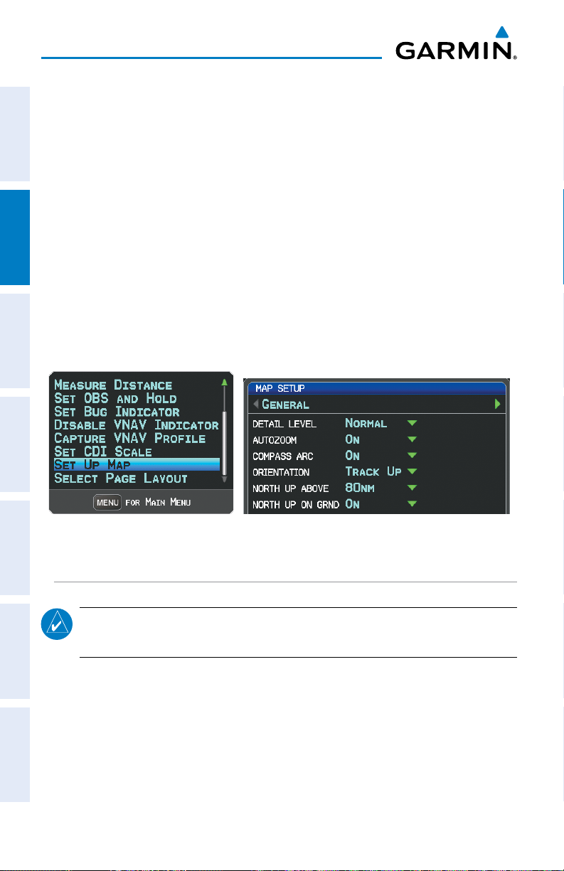
GPS Navigation
b)
Turn the FMS Joystick to access a list of available options.
c)
Turn or move the FMS Joystick to highlight ‘North Up’, ‘Track Up’, or
‘DTK Up’, and press the ENT Key.
OverviewGPS NavigationFlight PlanningHazard AvoidanceAdditional FeaturesAppendicesIndex
Or
:
a)
Move the FMS Joystick to highlight the ‘North Up Above’ field.
b)
Turn the FMS Joystick to access a list of available range options.
c)
Turn or move the FMS Joystick to highlight the desired range above
which to display North Up orientation.
Or
:
a)
Move the FMS Joystick to highlight the ‘North Up On GRND’ field.
b)
Using the FMS Joystick highlight ‘On’ or ‘Off’, and press the ENT Key.
When ‘North Up On GRND’ is ‘ON’ (default), the map orientation will
change to North Up when the aircraft is on the ground.
Map Page Menu General Menu (Map Setup Page)
MAP RANGE
NOTE: Refer to the Additional Features section for information on changing the
FliteCharts®, or ChartView range.
There are 23 different map ranges available, from 200 feet to 800 nm. The current
range is indicated in the lower right corner of the map. The scale bar represents the
map scale. To change the map range on any map, use the down arrow on the RNG
Key to zoom in (decreasing), or the up arrow to zoom out (increasing).
When the selected range exceeds the resolution of the map data, ‘overzoom’
appears below the map range scale.
48
Garmin GPSMAP 695/696 Owner’s Manual
190-00919-00 Rev. F
Page 65

GPS Navigation
Scale Bar Representing a Map
Scale of 1.2
nm Per Scale
Width.
Map Range/Overzoom
AUTO ZOOM
Auto Zoom allows the GPSMAP 695/696 to change the map display range to the
smallest range clearly showing the active waypoint. Auto Zoom can be overridden by
adjusting the range and remains that way until the active waypoint changes, a terrain
or traffic alert occurs, or the aircraft takes off.
Enabling/disabling autozoom:
1)
With the Map Page displayed, press the MENU Key.
2)
Turn or move the FMS Joystick to highlight ‘Set Up Map’ and press the
ENT Key.
3)
Turn the FMS Joystick to highlight the ‘General’ Menu.
4)
Move the FMS Joystick to highlight the ‘Autozoom’ field.
5)
Turn the FMS Joystick to access the ‘On/Off’ drop down list.
6)
Turn or move the FMS Joystick to highlight the desired option, and press
the ENT Key.
Overview GPS Navigation Flight Planning Hazard Avoidance Additional Features Appendices Index
MAP PANNING
Map panning allows the pilot to:
•Viewpartsofthe map outsidethedisplayed rangewithout adjustingthemap
range
•Highlightandselectlocationsonthemap
•Reviewinformationforaselectedairport,NAVAID,oruserwaypoint
•Designatelocationsforuseinightplanning
•Viewairspaceandairwayinformation
190-00919-00 Rev. F
Garmin GPSMAP 695/696 Owner’s Manual
49
Page 66

GPS Navigation
When the panning function is selected by pressing the FMS Joystick (PAN MAP
Softkey on the Weather Page) the Map Pointer flashes on the map display. A window
also appears at the top of the map display showing the latitude/longitude position of
the pointer, the bearing and distance to the pointer from the aircraft’s present position,
OverviewGPS NavigationFlight PlanningHazard AvoidanceAdditional FeaturesAppendicesIndex
the elevation of the land at the position of the pointer, or the object’s (airports,
obstacles, etc) elevation, if known.
When the Map Pointer is placed on a map feature, the map feature is highlighted
and an information box appears (even if the name was not originally displayed on the
map).
Pressing the ENT Key displays a review page for the highlighted map feature. If
multiple features are present at the Map Pointer position, a green arrow will appear
in the information box. Turning the FMS Joystick will cycle through the list of map
features present at that position.
Bearing and Dis-
tance to the Pointer
from the Aircraft’s
Present Position
Elevation and ETE
to the Pointer
Pointer Location
(Name)
Information Box
Panning the map:
1)
Press the FMS Joystick (or PAN MAP Softkey on the Weather (WX) Page)
to display the Map Pointer.
2)
Move the FMS Joystick to move the Map Pointer around the map.
3)
Press the FMS Joystick to remove the Map Pointer and re-center the map
on the aircraft’s current position.
50
Map Panning (Map Page)
Garmin GPSMAP 695/696 Owner’s Manual
Latitude/
Longitude
Position of
the Pointer
Green Arrow
Indicating
Multiple
Features are
Present at the
Map Pointer
Location.
Map Pointer
190-00919-00 Rev. F
Page 67

GPS Navigation
Reviewing information for a map or weather feature:
1)
Place the Map Pointer on a map feature. If multiple map features are
Overview GPS Navigation Flight Planning Hazard Avoidance Additional Features Appendices Index
present at the Map Pointer position (green arrow in the information box),
turn the FMS Joystick to cycle through the list.
2)
Press the ENT Key to display the review page for the highlighted feature.
3)
Press the FMS Joystick, the CLR Key, or the ENT Key to exit the review
page and return to the Map Page showing the selected waypoint.
MEASURING BEARING AND DISTANCE
Distance and bearing from the aircraft’s present position to any point on the viewable
navigation map may be calculated using the ‘Measure Distance’ selection from Map
Page menu. The distance tool displays a dashed Measurement Line and a Map Pointer
to aid in graphically identifying points to measure. Lat/Long, bearing, distance and
elevation data for the Map Pointer is provided in a window at the top of the Map Page.
Measuring bearing and distance between any two points:
1)
From the Map Page, press the MENU Key.
2)
Turn or move the FMS Joystick to highlight the ‘Measure Distance’ field
and press the ENT Key. A Measure Pointer is displayed on the map at the
aircraft’s present position.
3)
Move the FMS Joystick to place the reference pointer at the desired
location. The bearing and distance are displayed at the top of the map.
Elevation at the current pointer position is also displayed. Pressing the ENT
Key changes the starting point for measuring.
4)
To exit the Measure Bearing/Distance option, press the FMS Joystick; or
select ‘Stop Measuring’ from the Page Menu and press the ENT Key.
Measurement LineReference Point
Map Page Menu Map Page (Measure Distance)
190-00919-00 Rev. F
Garmin GPSMAP 695/696 Owner’s Manual
Map
Pointer
51
Page 68

GPS Navigation
TOPOGRAPHY
Topographic data can be displayed or removed as described in the following
procedures.
OverviewGPS NavigationFlight PlanningHazard AvoidanceAdditional FeaturesAppendicesIndex
Displaying/removing topographic data:
1)
Press the MAP Softkey on the Map Page. Press the VFR MAP Softkey if
necessary.
2)
Press the TOPO Softkey. Topographic data is displayed.
3)
Press the TOPO Softkey again to remove topographic data from the
Navigation Map.
Or
:
1)
From the Map Page, press the MENU Key.
2)
Turn or move the FMS Joystick to highlight ‘Set Up Map’, and press the
ENT Key.
3)
Turn the FMS Joystick to highlight the ‘Map’ Category from the horizontal
list.
4)
Move the FMS Joystick to highlight the ‘Topo Shading’ field.
5)
Turn the FMS Joystick to select ‘On’ or ‘Off’, and press the ENT Key.
VFR MAP Softkey
52
Topographic Data (Map Page)
Garmin GPSMAP 695/696 Owner’s Manual
TOPO Softkey
190-00919-00 Rev. F
Page 69

GPS Navigation
SATELLITE VIEW
The Satellite View displays satellite imagery above 20nm.
Displaying/removing satellite imagery on the map page:
1)
Press the MAP Softkey on the Map Page. Press the VFR MAP Softkey (if
necessary).
2)
Press the SAT VIEW Softkey. Satellite imagery is displayed on the map.
3)
Press the SAT VIEW Softkey again to remove satellite imagery from the
Navigation Map.
Or
:
1)
From the Map Page, press the MENU Key.
2)
Turn or move the FMS Joystick to highlight ‘Set Up Map’, and press the
ENT Key.
3)
Turn the FMS Joystick to highlight the ‘Map’ Category from the horizontal
list.
4)
Move the FMS Joystick to highlight the ‘Satellite View’ field.
5)
Turn the FMS Joystick to select ‘On’ or ‘Off’, and press the ENT Key.
Overview GPS Navigation Flight Planning Hazard Avoidance Additional Features Appendices Index
VFR MAP Softkey
190-00919-00 Rev. F
Satellite View (Map Page)
Garmin GPSMAP 695/696 Owner’s Manual
SAT VIEW Softkey
53
Page 70

GPS Navigation
MAP SYMBOLS
Refer to Appendix G for a list of map symbols.
OverviewGPS NavigationFlight PlanningHazard AvoidanceAdditional FeaturesAppendicesIndex
MAP DECLUTTER
The pilot can remove (declutter) unwanted items, such as highways from the map.
Decluttering the Map Page:
1)
From any Map Page, press the CLR Key. ‘CLEAR-1’ appears below the
map range. The background symbols (such as highways, cities, rivers, and
smaller lakes) are removed from the map.
2)
Press the CLR Key again. ‘CLEAR-2’ appears below the map range and
airspace boundary detail is removed from the map.
3)
Press the CLR Key again. ‘CLEAR-3’ appears below the map range. Only
the waypoints and navaids that are part of the current flight plan appear on
the map.
4)
Press the CLR Key again to return ‘ALL’ detail to the map.
Map Declutter
MAP DETAIL
The map detail can also be adjusted. Map detail changes the amount of detail with
respect to the zoom scale.
Adjusting the map detail:
1)
From the Map Page, press the MENU Key.
2)
Turn or move the FMS Joystick to highlight ‘Set Up Map’, and press the
ENT Key.
3)
Turn the FMS Joystick to highlight the ‘General’ Category from the
horizontal list.
4)
Move the FMS Joystick to highlight the ‘Detail Level’ field.
5)
Turn the FMS Joystick to select the desired detail level (‘Most’, ‘More’,
‘Normal’, ‘Less’, or ‘Least’), and press the ENT Key.
54
Garmin GPSMAP 695/696 Owner’s Manual
190-00919-00 Rev. F
Page 71

GPS Navigation
AIRPORTS & NAVAIDS
Airport and NAVAID information can be customized to display a variety of information
including: runway extension lines, runway numbers and visual reporting points (VRP).
Runway
Number
Runway
Extension
line
Runway Extensions and Numbers (Map Page)
Overview GPS Navigation Flight Planning Hazard Avoidance Additional Features Appendices Index
Setting up and customizing airports and NAVAIDs for the map
page:
1)
From the Map Page press the MENU Key.
2)
Turn or move the FMS Joystick to highlight ‘Set Up Map’ and press the
ENT Key.
3)
Turn the FMS Joystick to select the ‘Airport’ or ‘NAVAID’ Category from the
horizontal list.
4)
Move the FMS Joystick to highlight the desired feature.
5)
Turn the
FMS
Joystick to access a list of options for each feature (On/Off,
Auto, range settings, or text size).
6)
Using the
7)
Press the FMS Joystick, the CLR Key, or the EXIT Softkey to return to the
FMS
Joystick select the desired option and press the
Map Page with the changed settings.
190-00919-00 Rev. F
Garmin GPSMAP 695/696 Owner’s Manual
ENT
Key.
55
Page 72

GPS Navigation
OverviewGPS NavigationFlight PlanningHazard AvoidanceAdditional FeaturesAppendicesIndex
Map Setup Page (Airport Category) Map Setup Page (NAVAID Category)
CITIES & ROADS
Setting up and customizing cities and roads for the map page:
1)
From the Map Page press the MENU Key.
2)
Turn or move the FMS Joystick to highlight ‘Set Up Map’ and press the
ENT Key.
3)
Turn the FMS Joystick to select the ‘City’ or ‘Road’ Category from the
horizontal list.
4)
Move the FMS Joystick to highlight the desired feature.
5)
Turn the
Auto, range settings, or text size).
6)
Using the
7)
Press the FMS Joystick, the CLR Key, or the EXIT Softkey to return to the
Map Page with the changed settings.
FMS
Joystick to access a list of options for each feature (On/Off,
FMS
Joystick select the desired option and press the
ENT
Key.
Map Setup Page (City Category) Map Setup Page (Road Category)
56
Garmin GPSMAP 695/696 Owner’s Manual
190-00919-00 Rev. F
Page 73

GPS Navigation
AIRSPACE
Setting up and customizing airspace for the map page:
1)
From the Map Page press the MENU Key.
2)
Turn or move the FMS Joystick to highlight ‘Set Up Map’ and press the
ENT Key.
3)
Turn the FMS Joystick to select the ‘Airspace’ or ‘SUA’ (Special Use
Airspace) Category from the horizontal list.
4)
Move the FMS Joystick to highlight the desired feature.
5)
Turn the
Auto, or range settings).
6)
Using the
7)
Press the FMS Joystick, the CLR Key, or the EXIT Softkey to return to the
Map Page with the changed settings.
FMS
Joystick to access a list of options for each feature (On/Off,
FMS
Joystick select the desired option and press the
ENT
Overview GPS Navigation Flight Planning Hazard Avoidance Additional Features Appendices Index
Key.
Map Setup Page (Airspace Category) Map Setup Page (SUA Category)
AIRWAYS
Low Altitude Airways (or Victor Airways) primarily serve smaller piston-engine,
propeller-driven airplanes on shorter routes and at lower altitudes. Airways are eight
nautical miles wide and start 1,200 feet above ground level (AGL) and extend up
to but not including 18,000 feet mean sea level (MSL). Low Altitude Airways are
designated with a “V” before the airway number (hence the name “Victor Airways”)
since they run primarily between VORs.
High Altitude Airways (or Jet Routes) primarily serve airliners, jets, turboprops, and
turbocharged piston aircraft operating above 18,000 feet MSL. Jet Routes start at
18,000 feet MSL and extend upward to 45,000 feet MSL (altitudes above 18,000 feet
190-00919-00 Rev. F
Garmin GPSMAP 695/696 Owner’s Manual
57
Page 74

GPS Navigation
are called “flight levels” and are described as FL450 for 45,000 feet MSL). Jet Routes
are designated with a “J” before the route number.
Low Altitude Airways are drawn in gray. High Altitude Airways are drawn in green.
OverviewGPS NavigationFlight PlanningHazard AvoidanceAdditional FeaturesAppendicesIndex
When both types of airways are displayed, high altitude airways are drawn on top of
Low Altitude Airways.
When airways are selected for display on the map, the airway waypoints (VORs,
NDBs, and Intersections) are also displayed.
IFR Map - Low Airways
(Victor Airways)
IFR Map - High Airways
(Jet Routes)
Airways may be displayed on the map at the pilot’s discretion using the MAP Softkey
on the Map Page.
Displaying/removing airways:
1)
Select the MAP Softkey on the Map Page.
2)
Select the IFR MAP Softkey to display the IFR Map and related softkeys.
3)
Select/deselect the LOW AWY Softkey to display/remove the Low Altitude
Airways.
4)
Select/deselect the HIGH AWY Softkey to display/remove the High Altitude
Airways.
5)
Press the BACK Softkey to return to the top-level softkeys.
Reviewing information for an airway:
1)
From the Map Page, press the MAP Softkey.
2)
Press the IFR MAP Softkey (if necessary).
3)
With the LOW AWY and/or HIGH AWY Softkeys selected, press the FMS
Joystick to display the Map Pointer.
58
Garmin GPSMAP 695/696 Owner’s Manual
190-00919-00 Rev. F
Page 75

GPS Navigation
4)
Place the Map Pointer on an airway. The MEA, name of airway, endpoints,
distance, and calculated radials are displayed.
Overview GPS Navigation Flight Planning Hazard Avoidance Additional Features Appendices Index
Calculated
Radial
Reviewing Airway Information (Map Page)
5)
Press the ENT Key to display the review page for the airway.
-MEA
-Airway Name
-Endpoints
-Distance
Calculated Radial
6)
Press the FMS Joystick, the CLR Key, or the ENT Key to exit the review
page and return to the Map Page.
190-00919-00 Rev. F
Low Altitude Airway Review Page
Garmin GPSMAP 695/696 Owner’s Manual
59
Page 76

GPS Navigation
2.5 WAYPOINTS
The Waypoint (WPT) Page provides airport and waypoint information.
OverviewGPS NavigationFlight PlanningHazard AvoidanceAdditional FeaturesAppendicesIndex
Waypoints are predetermined geographical positions (internal database) or pilot-
entered positions, and are used for all phases of flight planning and navigation.
Waypoints can be selected by entering the ICAO identifier, entering the name
of the facility, or by entering the city name. As a waypoint identifier, facility name,
or location is entered, the GPSMAP 695/696’s Spell’N’Find feature scrolls through
the database, displaying those waypoints matching the characters which have been
entered up to that point. A direct-to navigation leg to the selected waypoint can be
initiated by pressing the Direct-to Key from the Waypoint Page.
The Waypoint Page allows the pilot to review airport information, runway
information, frequencies, instrument procedures, Airport Directory information, and
weather information. The pilot can manually enter the identifier or the GPSMAP
695/696 will choose the most appropriate identifier based on the current position
and phase of flight.
The following descriptions and abbreviations are used:
•Usagetype:Public,Military,orPrivate
•Runwaysurfacetype:Hard,Turf,Sealed,Gravel,Dirt,Soft,Unknown,orWater
•Runwaylightingtype:NoLights,PartTime,FullTime,Unknown,orPCLFreq(for
pilot-controlled lighting)
•COMAvailability:TX(transmitonly),RX(receiveonly),PT(parttime),* (additional
information available)
60
Garmin GPSMAP 695/696 Owner’s Manual
190-00919-00 Rev. F
Page 77

-Waypoint Identifier/Symbol/Type
-Facility Name
-City/Region
GPS Navigation
Overview GPS Navigation Flight Planning Hazard Avoidance Additional Features Appendices Index
-Region
-Country
Runway Information
-Designation
-Length/Width
-Surface
-Lighting
-Displaced Threshold
Distance
-Traffic Pattern
-Wind Speed/Direction
Map
Showing
Selected
Waypoint
Airport
COM/NAV
Freq. Info.
-Identification
-Frequency
-Availability
-Additional
Information
Information
-Elevation
-Fuel Available
-Time Zone
-UTC Offset
-Daylight Savings
Time
-Lat/Long
-Bearing/Distance
INFO Softkey
Selected
Waypoint Page (INFO Softkey Selected)
Selecting an airport for review by identifier, facility name, or location:
1)
From the Waypoint (WPT) Page, press the INFO Softkey.
2)
Press the FMS Joystick to activate the cursor.
3)
Turn the FMS Joystick clockwise to begin entering a waypoint identifier
(turning it counter-clockwise brings up the waypoint selection submenu press the CLR Key to remove it), or move the FMS Joystick to select the
facility name, or city field.
4)
Press the ENT Key.
190-00919-00 Rev. F
Garmin GPSMAP 695/696 Owner’s Manual
61
Page 78

GPS Navigation
If duplicate entries exist for the entered facility name or location, additional entries may be
viewed by continuing to turn the FMS Joystick during the selection process. If duplicate entries
exist for an identifier, a Duplicate Waypoints Window is displayed. Press the ENT Key to move
the cursor to the Duplicate Waypoints Window.
OverviewGPS NavigationFlight PlanningHazard AvoidanceAdditional FeaturesAppendicesIndex
Duplicate
Waypoints
Window
Waypoint Information Window-Duplicate Identifier
Selecting a runway:
1) With the Waypoint (WPT) Page displayed, press the INFO Softkey.
2) Press the FMS Joystick to activate the cursor.
3) Turn the FMS Joystick clockwise to begin entering a waypoint identifier for the
desired runway (turning it counter-clockwise brings up the waypoint selection
submenu - press the CLR Key to remove it), or move the FMS Joystick to select the
facility name, or city field.
4) Press the ENT Key.
5) Move the FMS Joystick to place the cursor in the ‘Runways’ Box, on the runway
designator.
62
Runways Box (Waypoint Page)
6)
Turn the FMS Joystick to display the desired runway (if more than one) for
the selected airport.
Garmin GPSMAP 695/696 Owner’s Manual
190-00919-00 Rev. F
Page 79

GPS Navigation
FREQUENCIES
The Frequencies Box uses the descriptions and abbreviations listed in the follow-
ing table:
Communication Frequencies Navigation
Frequencies
Approach *
Arrival *
ASOS
ATIS
AWOS
Center
Class B *
Class C *
Control
CTA *
Departure *
Gate
Ground
Helicopter
Multicom
Other
Clearance
* May include Additional Information
Frequency Abbreviations
The frequencies may be denoted by ‘RX’, ‘TX’, or ‘CTAF’ if applicable.
Viewing additional information for a frequency:
1)
With the Waypoint (WPT) Page displayed, press the INFO Softkey.
2)
Press the FMS Joystick to activate the cursor.
3)
Move the FMS Joystick to place the cursor in the ‘Frequencies’ Box, on the
frequency denoted with an *.
Pre-Taxi
Radar
Ramp
Terminal*
TMA *
Tower
TRSA *
Unicom
ILS
LOC
Overview GPS Navigation Flight Planning Hazard Avoidance Additional Features Appendices Index
190-00919-00 Rev. F
Additional Frequency Information
(Waypoint Page)
Garmin GPSMAP 695/696 Owner’s Manual
63
Page 80

GPS Navigation
4)
Press the ENT Key to view the Additional Information Window.
5)
To remove the window, press the FMS Joystick, ENT Key, or CLR Key.
To quickly view the departure or destination airport information:
OverviewGPS NavigationFlight PlanningHazard AvoidanceAdditional FeaturesAppendicesIndex
1)
From the Waypoint (WPT) Page, press the INFO, CHART, AOPA, or
WEATHER Softkey.
2)
Press the MENU Key.
3)
Turn or move the FMS Joystick to highlight ‘View Destination Airport’ or
‘View Departure Airport’, and press the ENT Key.
NEAREST INFORMATION
The GPSMAP 695/696 provides a NRST Key which gives the pilot quick access to
nearest airport, weather, VOR, NDB, intersection, user waypoint, city, ARTCC, FSS, and
airspace information. If there are none available, “None Within 200 NM” is displayed.
Pressing the ENT Key displays the associated ‘Information Page’ for the highlighted
selection, similar to the Waypoint Page. Pressing the ENT Key again returns to the
Nearest Page.
Viewing nearest information:
1)
Press the NRST Key.
2)
Turn the FMS Joystick to select the desired Nearest Page (APT, WX, VOR,
NDB, INT, USR, CTY, ATC, FSS, or ASPC). If none are available, “None Within
200 NM” is displayed.
Or
: Press the NRST Key again to quickly select the nearest airport.
3)
Press the FMS Joystick to highlight the first selection in the list. Turn or
move the FMS Joystick to highlight the desired nearest option.
4)
Press the ENT Key to display the associated ‘Information Page’. From the
Airport Information Page and Weather Information Page, press the INFO,
CHART, AOPA / DIRECTORY, or WEATHER Softkeys for additional
information. From the User Waypoint Information Page, press the DELETE
or EDIT softkeys to make changes to the selected user waypoint.
5)
To return to the Nearest Page, press the FMS Joystick, the ENT Key, or the
CLR Key.
64
Garmin GPSMAP 695/696 Owner’s Manual
190-00919-00 Rev. F
Page 81

GPS Navigation
Overview GPS Navigation Flight Planning Hazard Avoidance Additional Features Appendices Index
Nearest Airports Page
Airport Information Page
NEAREST AIRPORT CRITERIA
From the Menu on the Nearest Airports Page the pilot can define the minimum
runway length and surface type used when determining the 15 nearest airports to
display on the Nearest Airports Page. A minimum runway length and/or surface
type can be entered to prevent airports with small runways or runways that are not
appropriately surfaced from being displayed. Default settings are 0 feet (or meters)
for runway length and “Any” for runway surface type. Private airports and Heliports
can also be included.
The Page Menu also allows the pilot to choose between displaying the facility names,
city names, bearing, or direction arrows.
To quickly show/hide private airport and heliports from the Nearest Airports Page,
press the PRIVATE or HELIPORT Softkeys.
Setting nearest airport criteria:
1)
With the Nearest Airports Page displayed, press the MENU Key.
2)
Turn or move the FMS Joystick to select 'Set Airport Criteria' from the Page
Menu.
190-00919-00 Rev. F
Garmin GPSMAP 695/696 Owner’s Manual
65
Page 82

GPS Navigation
3)
Press the ENT Key. The Airport Criteria Window is displayed.
4)
Move the FMS Joystick to select the desired criteria to be defined.
5)
Turn the FMS Joystick to select the desired option.
OverviewGPS NavigationFlight PlanningHazard AvoidanceAdditional FeaturesAppendicesIndex
6)
Press the ENT Key.
Nearest Airports Page Menu Airport Criteria Window
Restoring nearest airport criteria defaults:
1)
With the Nearest Airports Page displayed, press the MENU Key.
2)
Turn or move the FMS Joystick to select ‘Set Airport Criteria’ from the Page
Menu.
3)
Press the ENT Key. The Airport Criteria Window is displayed.
4)
Press the MENU Key.
5)
With ‘Restore Default’ highlighted, press the ENT Key.
WEATHER INFORMATION
Textual weather information can be viewed from the Waypoint Page or the Nearest
WX Page. Refer to the Hazard Avoidance section for information on SiriusXM Weather
and FIS-B.
Selecting airport weather information:
1)
From the Waypoint Page, press the WEATHER Softkey.
2)
Press the FMS Joystick to activate the cursor.
3)
Turn the FMS Joystick clockwise to begin entering an airport identifier
(turning it counter-clockwise brings up the waypoint selection submenu press the CLR Key to remove it).
4)
Press the ENT Key.
Or
:
66
Garmin GPSMAP 695/696 Owner’s Manual
190-00919-00 Rev. F
Page 83

GPS Navigation
1)
Press the NRST Key.
2)
Turn the FMS Joystick to select the Nearest Airport WX Page. If Nearest
Airport Weather is not available, “None Within 200 NM” is displayed.
3)
Press the NRST Key again or press the FMS Joystick to highlight the first
airport in the nearest airport weather list. Turn or move the FMS Joystick
to highlight the desired airport weather.
4)
Press the ENT Key to display the Weather Information Page.
5)
Turn the FMS Joystick to scroll up or down on the page.
6)
To return to the Nearest Airport Weather Page, press the FMS Joystick, the
ENT Key, or the CLR Key.
Overview GPS Navigation Flight Planning Hazard Avoidance Additional Features Appendices Index
Nearest Airport Weather Page Weather Information Page
190-00919-00 Rev. F
Garmin GPSMAP 695/696 Owner’s Manual
67
Page 84

GPS Navigation
INTERSECTIONS
Intersections can be viewed from the Waypoint Page or the Nearest Intersections
Page. In addition to displaying a map of the currently selected intersection and
OverviewGPS NavigationFlight PlanningHazard AvoidanceAdditional FeaturesAppendicesIndex
surrounding area, the Intersection Information Page displays the region, bearing,
distance, latitude, and longitude.
Select an intersection:
1)
From the Waypoint Page, press the INFO Softkey.
2)
Press the FMS Joystick to activate the cursor.
3)
Turn the FMS Joystick clockwise to begin entering an intersection identifier
(turning it counter-clockwise brings up the waypoint selection submenu press the CLR Key to remove it), or move the FMS Joystick to select the
facility name, or city field.
4)
Press the ENT Key.
Or
:
1)
Press the NRST Key.
2)
Turn the FMS Joystick to select the Nearest Intersections Page.
3)
Press the FMS Joystick to activate the cursor.
4)
Turn or move the FMS Joystick to highlight the desired intersection.
5)
Press the ENT Key to display the Intersection Information Page.
NDBS
NDBs can be viewed from the Waypoint Page or the Nearest NDBs Page. In addition
to displaying a map of the currently selected NDB and surrounding area, the page
displays the region, bearing, distance, latitude, longitude and frequency.
The Nearest NDB Page can be used to quickly find a NDB close to the flight path.
The list only includes NDBs that are within 200nm. If there are no NDBs in the list, text
indicating that there are no nearest NDBs is displayed. If there are no nearest NDBs in
the list, the information and frequency fields are dashed.
Select an NDB:
1)
From the Waypoint Page, press the INFO Softkey if necessary.
2)
Press the FMS Joystick to activate the cursor.
68
Garmin GPSMAP 695/696 Owner’s Manual
190-00919-00 Rev. F
Page 85

GPS Navigation
3)
Turn the FMS Joystick clockwise to begin entering the identifier (turning
it counter-clockwise brings up the waypoint selection submenu - press the
CLR Key to remove it), or move the FMS Joystick to select the facility name,
or city field.
4)
Press the ENT Key.
Or
:
1)
Press the NRST Key.
2)
Turn the FMS Joystick to select the Nearest NDBs Page.
3)
Press the FMS Joystick to activate the cursor.
4)
Turn the FMS Joystick to highlight the desired NDB.
5)
Press the ENT Key to display the NDB Information Page.
VORS
VORs can be viewed from the Waypoint Page or the Nearest NDBs Page. In addition
to displaying a map of the currently selected VOR and surrounding area, the page
displays the region, city, state, bearing, distance, latitude, longitude, frequency and
class (High, Low, or Terminal VOR).
Overview GPS Navigation Flight Planning Hazard Avoidance Additional Features Appendices Index
The Nearest VOR Page can be used to quickly find a VOR close to the flight path.
The list only includes VORs that are within 200nm. If there are no VORs in the list, text
indicating that there are no nearest VORs is displayed. If there are no nearest VORs in
the list, the information and frequency fields are dashed.
Localizer information cannot be viewed on the VOR Information Page. If a VOR station
is combined with a TACAN station it is listed as a VORTAC on the VOR Information
Page and if it includes only DME, it’s displayed as VOR-DME.
Select an VOR:
1)
From the Waypoint Page, press the INFO Softkey.
2)
Press the FMS Joystick to activate the cursor.
3)
Turn the FMS Joystick clockwise to begin entering identifier (turning it
counter-clockwise brings up the waypoint selection submenu - press the
CLR Key to remove it), or move the FMS Joystick to select the facility name,
or city field.
4)
Press the ENT Key.
190-00919-00 Rev. F
Garmin GPSMAP 695/696 Owner’s Manual
69
Page 86

GPS Navigation
Or
:
1)
Press the NRST Key.
2)
Turn the FMS Joystick to select the Nearest VOR Page.
OverviewGPS NavigationFlight PlanningHazard AvoidanceAdditional FeaturesAppendicesIndex
3)
Press the FMS Joystick to activate the cursor.
4)
Turn the FMS Joystick to highlight the desired VOR.
5)
Press the ENT Key to display the VOR Information Page.
USER WAYPOINTS
The GPSMAP 695/696 can create and store up to 3,000 user-defined waypoints.
Once a waypoint has been created, it can be renamed, deleted, or moved.
Creating user waypoints:
1)
To create a user waypoint at the current location, using the Map Pointer, or
from the Main Menu:
a)
To create a user waypoint at the current location, press and hold the
ENT Key from any page.
b)
The ‘Mark a New User Waypoint? window appears.
Or
:
a)
Press the MENU Key twice to access the Main Menu.
b)
Move the FMS Joystick to highlight ‘User Waypoints’ and press the ENT
Key.
70
Main Menu (User Waypoints Selected)
c)
Press the NEW Softkey. The message “Create a New User Waypoint?”
message is displayed. The current aircraft position is the default location of
the new waypoint.
Garmin GPSMAP 695/696 Owner’s Manual
190-00919-00 Rev. F
Page 87

GPS Navigation
Or
:
a)
From a map page, press the FMS Joystick to activate the Map Pointer
(on the WX Page, press the PAN MAP Softkey or press Menu, then ‘Show
Map Point’).
b)
Find an empty area without any map features and press the ENT Key.
The message “Create a New User Waypoint?” message is displayed.
Or
:
a)
From a map page, press the FMS Joystick to activate the Map Pointer
(on the WX Page, press the PAN MAP Softkey) (‘Create User Waypoint’ is
not available in the WX Page Menu).
b)
Select a map feature using the Map Pointer and press the MENU Key.
c)
With ‘Create User Waypoint’ highlighted, press the ENT Key. The
message “Create a New User Waypoint?” message is displayed.
2)
With ‘Yes’ highlighted, press the ENT Key. The New Waypoint Window is
displayed.
3)
Move the FMS Joystick to the User Waypoint Name Field and enter the
waypoint name, if desired.
4)
If desired, select the waypoint symbol:
a)
Move the FMS Joystick to highlight the Symbol.
b)
Turn the FMS Joystick to access the ‘Select Symbol’ Menu.
c)
Turn or move the FMS Joystick to highlight the desired symbol from the
menu, and press the ENT Key.
Symbol Field (Selected) User Waypoint Name Field
Overview GPS Navigation Flight Planning Hazard Avoidance Additional Features Appendices Index
190-00919-00 Rev. F
New Waypoint Window (Symbol Selected)
Garmin GPSMAP 695/696 Owner’s Manual
71
Page 88

GPS Navigation
5)
If desired, press the POSITION Softkey and enter the latitude, longitude,
name, or altitude for the waypoint or press the REF WPTS Softkey to enter
a bearing and distance from another waypoint or the bearing from two
OverviewGPS NavigationFlight PlanningHazard AvoidanceAdditional FeaturesAppendicesIndex
other waypoints to define the new waypoint location.
New Waypoint Window
(POSITION Softkey Selected)
6)
With ‘Done’ highlighted, press the ENT Key.
New Waypoint Window
(REF WPTS Softkey Selected)
Selecting and viewing nearest user waypoints:
1)
Press the NRST Key.
2)
Turn the FMS Joystick to select the Nearest USR Page.
3)
Press the FMS Joystick to activate the cursor.
4)
Turn the FMS Joystick to highlight the desired user waypoint.
5)
Press the ENT Key to display the User Waypoint Information Window.
Editing or renaming a user waypoint:
1)
Press the MENU Key twice to access the Main Menu.
2)
Move the FMS Joystick to highlight ‘User Waypoints’ and press the ENT
Key.
3)
Move the FMS Joystick to highlight the appropriate waypoint and press the
EDIT Softkey. The Edit Waypoint Window is displayed.
4)
Move the cursor to the desired field(s) and make any necessary changes (to
edit the Reference Waypoints, press the REF WPTS Softkey).
5)
With ‘Done’ highlighted, press the ENT Key.
72
Garmin GPSMAP 695/696 Owner’s Manual
190-00919-00 Rev. F
Page 89
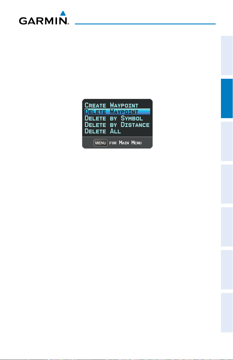
GPS Navigation
Deleting user waypoints:
1)
Press the MENU Key twice to access the Main Menu.
2)
Turn or Move the FMS Joystick to highlight ‘User Waypoints’ and press the
ENT Key. If deleting all user waypoints, go to Step 4.
3)
Highlight a User Waypoint in the User Waypoint List, or enter a waypoint in
the User Waypoint field.
4)
Press the MENU Key.
User Waypoints Page Menu
5)
Select ‘Delete Waypoint’ or ‘Delete All’.
6)
Press the ENT Key. ‘No’ is highlighted in the confirmation window.
7)
With ‘Yes’ highlighted in the confirmation window, press the ENT Key.
Or
:
1)
Press the MENU Key twice to access the Main Menu.
2)
Turn or Move the FMS Joystick to highlight ‘User Waypoints’ and press the
ENT Key.
3)
Highlight a User Waypoint in the User Waypoint List, or enter a waypoint in
the User Waypoint field.
4)
Press the ENT Key.
5)
Press the DELETE Softkey. ‘No’ is highlighted in the confirmation window.
6)
Highlight ‘Yes’ and press the ENT Key.
Overview GPS Navigation Flight Planning Hazard Avoidance Additional Features Appendices Index
User Waypoints can also be deleted by ‘Symbol’ or ‘Distance’ from the User
Waypoints Page Menu.
190-00919-00 Rev. F
Garmin GPSMAP 695/696 Owner’s Manual
73
Page 90

GPS Navigation
2.6 AIRSPACE
The GPSMAP 695/696 can display the following types of airspaces: Class B/TMA, Class
C/TCA, Class D, Restricted, MOA (Military), Other Airspace, Air Defense Identification
OverviewGPS NavigationFlight PlanningHazard AvoidanceAdditional FeaturesAppendicesIndex
Zone (ADIZ), and Temporary Flight Restriction (TFR), and Parachute Jump Areas.
The Nearest Airspace Page and Airspace Alerts provide information about airspaces
and the location of the aircraft in relationship to them. The Nearest Airspace Page can
be used to quickly find airspaces close to the flight path.
The Nearest Airspace Page displays the class of airspace, controlling agency, vertical
boundaries, and status.
Selecting and viewing nearest airspaces:
1)
Press the NRST Key.
2)
Turn the FMS Joystick to select the Nearest Airspace Page.
3)
Press the FMS Joystick to highlight the nearest airspace. Turn or move the
FMS Joystick to highlight the desired airspace.
4)
Press the ENT Key to display the Airspace Information Page.
5)
Press the FREQS Softkey (if available) to display frequency and additional
airport information similar to the Waypoint Information Page.
74
Nearest Airspace Page Airspace Information Page
Garmin GPSMAP 695/696 Owner’s Manual
190-00919-00 Rev. F
Page 91

GPS Navigation
AIRSPACE ALERT MESSAGES
When an airspace alert appears, press the NRST Key to automatically show nearby
airspace information on the Nearest Airspace Page. This information includes name,
time to entry (if applicable), and status.
There are four types of status information:
•Ahead—Projectedtoentertheairspacewithinthenext10minutesorless.
•Near—Withintwonauticalmilesofanairspacebutnotprojectedtoenterit.
•Near & Ahead—Projecttoentertheairspacewithintwonauticalmiles.
•Inside Airspace—Withintheboundariesoftheairspace.
SMART AIRSPACE
Smart Airspace™ shows airspace at and immediately surrounding the aircraft’s
current altitude in bold. Airspaces at all other altitudes are de-emphasized.
De-emphasized
Airspace
™
Bold Airspace
Overview GPS Navigation Flight Planning Hazard Avoidance Additional Features Appendices Index
190-00919-00 Rev. F
Smart Airspace
Garmin GPSMAP 695/696 Owner’s Manual
™
75
Page 92

GPS Navigation
2.7 DIRECT-TO NAVIGATION
The Direct-to method of navigation, initiated by pressing the Direct to Key is quicker
to use than a flight plan when the desire is to navigate to a single point such as a
OverviewGPS NavigationFlight PlanningHazard AvoidanceAdditional FeaturesAppendicesIndex
nearby airport.
Once a direct-to is activated, the GPSMAP 695/696 establishes a point-to-point
course line from the present position to the selected direct-to destination. Course
guidance is provided until the direct-to is replaced with a new direct-to or flight plan,
or cancelled.
Entering a waypoint identifier, facility name, or city as a direct-to
destination:
1)
Press the Direct-to Key. The Direct-to Window is displayed (with the active
flight plan waypoint as the default selection or a blank waypoint field if no
flight plan is active).
2)
Turn the FMS Joystick clockwise to begin entering a waypoint identifier
(turning it counter-clockwise brings up the waypoint selection submenu press the CLR Key to remove it), press the RECENT Softkey to display a list
of recent waypoints, or move the FMS Joystick to select the facility name,
or city field.
3)
Press the ENT Key.
4)
With ‘Activate’ highlighted, press the ENT Key.
76
Direct-to Window
Garmin GPSMAP 695/696 Owner’s Manual
190-00919-00 Rev. F
Page 93

GPS Navigation
Selecting RECENT WPTS, NRST APTS, or FPL WPTS as a direct-to
destination:
1)
Press the Direct-to Key. The Direct-to Window is displayed (with the active
flight plan destination as the default selection or a blank destination if no
flight plan is active).
2)
Press the RECENT Softkey to display a list of recent waypoints (RECENT
WPTS) only or turn the FMS Joystick counter-clockwise to display a list of
recent waypoints (RECENT WPTS), nearest airports (NRST APTS), and flight
plan waypoints (FPL WPTS).
3)
Move the FMS Joystick to select the desired waypoint.
4)
Press the ENT Key.
5)
With ‘Activate’ highlighted, press the ENT Key.
Overview GPS Navigation Flight Planning Hazard Avoidance Additional Features Appendices Index
Flight Plan Waypoints (Direct-to Window)
Selecting a nearby airport as a direct-to destination:
1)
Press the NRST Key.
2)
Select the desired airport (the nearest one is already selected).
3)
Press the Direct-to Key.
4)
Press the ENT Key.
5)
With ‘Activate’ highlighted, press the ENT Key.
190-00919-00 Rev. F
Garmin GPSMAP 695/696 Owner’s Manual
77
Page 94

GPS Navigation
Direct-to destinations may also be selected by using the pointer on the navigation
map pages. If no airport, NAVAID, or user waypoint exists at the desired location, a
temporary waypoint named 'MAP POINTER' is automatically created at the location of
the map arrow.
OverviewGPS NavigationFlight PlanningHazard AvoidanceAdditional FeaturesAppendicesIndex
Selecting a waypoint as a direct-to destination using the pointer:
1)
From a navigation map page, press the FMS Joystick to display the pointer.
2)
Move the FMS Joystick to place the pointer at the desired destination
location.
3)
If the pointer is placed on an existing airport, NAVAID, or user waypoint, the
waypoint name is highlighted.
4)
Press the Direct-to Key to display the Direct-to Window with the selected
point entered as the direct-to destination.
5)
Press the ENT Key.
6)
With ‘Activate’ highlighted, press the ENT Key.
Cancelling a direct-to:
1)
Press the Direct-to Key to display the Direct-to Window.
2)
Move the FMS Joystick to highlight 'Stop Navigation' or ‘Resume Flight
Plan’ if a flight plan was active.
3)
Press the ENT Key. If a flight plan is still active, the GPSMAP 695/696
resumes navigating the flight plan along the closest leg.
78
Garmin GPSMAP 695/696 Owner’s Manual
190-00919-00 Rev. F
Page 95

Flight Planning
SECTION 3 FLIGHT PLANNING
Overview GPS Navigation Flight Planning Hazard Avoidance Additional Features Appendices Index
3.1 INTRODUCTION
Flight planning on the GPSMAP 695/696 consists of building a flight plan by
entering waypoints one at a time and inserting approaches as needed. The flight plan
is displayed on maps using different line widths, colors, and types, based on the type
of leg and the segment of the flight plan currently being flown.
Up to 50 flight plans with up to 300 waypoints each can be created and stored
in memory. One flight plan can be activated at a time and becomes the active flight
plan. The active flight plan is erased when the destination is reached and the system
is turned off. When storing flight plans with an approach, the GPSMAP 695/696
uses the waypoint information from the current database to define the waypoints. If
the database is changed or updated, the GPSMAP 695/696 automatically updates
the information if the procedure has not been modified. If an approach is no longer
available, the procedure is deleted from the affected stored flight plan(s), and an alert
is displayed.
Whenever an approach is loaded into the active flight plan it replaces the destination
airport with a sequence of waypoints for the selected approach. The airport must have
a published instrument approach and only the final course segment (usually from final
approach fix to missed approach point) of the published approach is available in the
GPSMAP 695/696.
DATA FIELDS
By default, the Data Fields on the Active and Saved Flight Plan Pages are set to
display Leg Desired Track (LEG DTK), Leg Distance (LEG DIS), and Leg Estimated Time
En Route (LEG ETE) or Leg Estimate Safe Altitude (LEG ESA) for a Saved Flight Plan.
The first two Data Fields can be changed using the Page Menu. The last Data Field can
be changed using the FMS Joystick.
Changing the information shown in the data fields:
From the Active Flight Plan Page or the Saved Flight Plan Page, move the
FMS Joystick (right or left) to quickly change the third data field.
190-00919-00 Rev. F
Garmin GPSMAP 695/696 Owner’s Manual
79
Page 96

Flight Planning
Or
:
1)
From the Active Flight Plan Page or the Saved Flight Plan Page, press the
OverviewGPS NavigationFlight PlanningHazard AvoidanceAdditional FeaturesAppendicesIndex
MENU Key.
2)
Turn or move the FMS Joystick to highlight ‘Change Data Fields’ and press
the ENT Key. The cursor is displayed on the first Data Field.
3)
If desired, move the FMS Joystick to highlight the second Data Field.
4)
Turn the FMS Joystick to access the list of available Data Fields.
5)
Turn or Move the FMS Joystick to highlight the desired option from the list
and press the ENT Key.
First Data
Field
Data Field Selection (Active Flight Plan Page)
Second Data
Field
Third Data
Field
80
Garmin GPSMAP 695/696 Owner’s Manual
190-00919-00 Rev. F
Page 97

Flight Planning
3.2 FLIGHT PLAN CREATION
The active flight plan is listed on the Active Flight Plan Page. It is the flight plan
to which the GPSMAP 695/696 is currently providing guidance, and is shown on the
navigation maps. Stored flight plans are listed on the Flight Plan List Page, and are
available for activation (becomes the active flight plan).
The Data Fields in the third column of the Active and Saved Flight Plan Pages can be
scrolled through by moving the FMS Joystick left or right. All other Data Fields can be
changed through the ‘Change Data Fields’ option of the Page Menu.
Data
Active
Leg
Fields
Overview GPS Navigation Flight Planning Hazard Avoidance Additional Features Appendices Index
190-00919-00 Rev. F
Non-
Active
Leg
Active
Leg
Active Flight Plan Page
Garmin GPSMAP 695/696 Owner’s Manual
81
Page 98

Flight Planning
Creating an active flight plan:
1)
Press the FPL Key.
2)
OverviewGPS NavigationFlight PlanningHazard AvoidanceAdditional FeaturesAppendicesIndex
Press the FMS Joystick to activate the cursor.
3)
Turn the FMS Joystick to display the Insert Waypoint Window. (Turning
it clockwise displays a blank Insert Waypoint Window, turning it counterclockwise displays a list of recent waypoints (RECENT WPTS), nearest
airports (NRST APTS), or flight plan waypoints (FPL WPTS)).
4)
Enter the identifier, facility, or city name of the departure waypoint or select
a waypoint from the submenu of waypoints and press the ENT Key. The
active flight plan is modified as each waypoint is entered.
5)
Repeat step numbers 3 and 4 to enter each additional flight plan waypoint.
6)
When all waypoints have been entered, press the FMS Joystick to remove
the cursor.
Creating a stored flight plan:
1)
Press the FPL Key.
2)
Turn the FMS Joystick to display the Flight Plan List Page.
3)
Press the NEW Softkey; or press the MENU Key, highlight ‘New Flight
Plan’, and press the ENT Key to display a blank flight plan for the first
empty storage location.
4)
Turn the FMS Joystick to display the Insert Waypoint Window (turning it
clockwise displays a blank Insert Waypoint Window, turning it counterclockwise displays the a list of recent waypoints (RECENT WPTS), nearest
airports (NRST APTS), or flight plan waypoints (FPL WPTS)).
82
Garmin GPSMAP 695/696 Owner’s Manual
Insert Waypoint Window
190-00919-00 Rev. F
Page 99

Flight Planning
5)
Enter the identifier, facility, or city name of the departure waypoint or select
a waypoint from the submenu of waypoints and press the ENT Key.
6)
Repeat steps 4 and 5 to enter each additional flight plan waypoint.
7)
When all waypoints have been entered, press the FMS Joystick to return to
the Flight Plan List Page. The new flight plan is now in the list.
ADDING WAYPOINTS TO AN EXISTING FLIGHT PLAN
Waypoints can be added to the active flight plan or any stored flight plan. Choose
the flight plan, select the desired point of insertion, enter the waypoint, and it is added
in front of the selected waypoint. Flight plans are limited to 300 waypoints (including
approach waypoints).
Adding a waypoint to a stored flight plan:
1)
On the Flight Plan List Page, press the FMS Joystick to activate the cursor.
2)
Turn or move the FMS Joystick to highlight the desired flight plan.
3)
Press the ENT Key.
4)
Move the FMS Joystick to select the point in the flight plan to add the new
waypoint. The new waypoint is placed directly in front of the highlighted
waypoint.
5)
Enter the new waypoint by one of the following:
a)
Turn the FMS Joystick clockwise to display a blank Insert Waypoint
Window.
b)
Using the FMS Joystick enter the identifier, facility, or city name of the
desired waypoint.
c)
Press the ENT Key.
O
r:
a)
Turn the FMS Joystick clockwise to display a blank Insert Waypoint
Window.
b)
Turn the FMS Joystick counter-clockwise to display a list of recent
waypoints (RECENT WPTS), nearest airports (NRST APTS), or flight plan
waypoints (FPL WPTS)).
c)
Select the desired waypoint from the submenu.
d)
Press the ENT Key.
Overview GPS Navigation Flight Planning Hazard Avoidance Additional Features Appendices Index
190-00919-00 Rev. F
Garmin GPSMAP 695/696 Owner’s Manual
83
Page 100

Flight Planning
O
r:
a)
Turn the FMS Joystick counter-clockwise to display a list of recent
OverviewGPS NavigationFlight PlanningHazard AvoidanceAdditional FeaturesAppendicesIndex
waypoints (RECENT WPTS), or nearest airports (NRST APTS).
c)
Select the desired waypoint from the submenu.
d)
Press the ENT Key.
Adding a waypoint to the active flight plan:
1)
Press the FPL Key.
2)
Press the FMS Joystick to activate the cursor.
3)
Using the FMS Joystick select the point in the flight plan before which to
add the new waypoint. The new waypoint is placed directly in front of the
highlighted waypoint.
4)
Turn the FMS Joystick to display the Insert Waypoint Window (Turning it
clockwise displays a blank Insert Waypoint Window, turning it counterclockwise displays the a list of recent waypoints (RECENT WPTS), nearest
airports (NRST APTS), or flight plan waypoints (FPL WPTS)).
5)
Enter the identifier, facility, or city name of the departure waypoint or select
a waypoint from the submenu of waypoints and press the ENT Key. The
active flight plan is modified as each waypoint is entered.
Loading an approach procedure into a stored flight plan:
An Approach Procedure can be loaded at any airport that has an approach available.
Only one approach can be loaded at a time in a flight plan. The route for a selected
approach is defined by designating transition waypoints.
1)
Press the FPL Key.
2)
Turn the FMS Joystick to select the Flight Plan List Page.
3)
Press the FMS Joystick to activate the cursor.
4)
Turn or move the FMS Joystick to highlight the desired flight plan and press
the ENT Key.
5)
Press the SEL APPR Softkey.
6)
Turn the FMS Joystick to display a drop down list of available approaches.
7)
Turn or move the FMS Joystick to highlight the desired approach and press
the ENT Key.
8)
With ‘Select Approach’ highlighted, press the ENT Key.
84
Garmin GPSMAP 695/696 Owner’s Manual
190-00919-00 Rev. F
 Loading...