

Page 1
GPSMAP® 5000 Series
owner’s manual
Page 2

© 2007 Garmin Ltd. or its subsidiaries
Garmin International, Inc.
1200 East 151st Street,
Olathe, Kansas 66062, USA
Tel. (913) 397.8200 or
(800) 800.1020
Fax (913) 397.8282
All rights reserved. Except as expressly provided herein, no part of this manual may be reproduced, copied,
transmitted, disseminated, downloaded or stored in any storage medium, for any purpose without the express prior
written consent of Garmin. Garmin hereby grants permission to download a single copy of this manual onto a hard
drive or other electronic storage medium to be viewed and to print one copy of this manual or of any revision hereto,
provided that such electronic or printed copy of this manual must contain the complete text of this copyright notice
and provided further that any unauthorized commercial distribution of this manual or any revision hereto is strictly
prohibited.
Information in this document is subject to change without notice. Garmin reserves the right to change or improve its
products and to make changes in the content without obligation to notify any person or organization of such changes
or improvements. Visit the Garmin Web site (www.garmin.com) for current updates and supplemental information
concerning the use and operation of this and other Garmin products.
Garmin® is a trademark of Garmin Ltd. or its subsidiaries, registered in the USA and other countries. Garmin
Mobile™, myGarmin™ GPSMAP®, AutoLocate®, TracBack®, BlueChart®, and MapSource® are trademarks of
Garmin Ltd. or its subsidiaries. These trademarks may not be used without the express permission of Garmin.
XM Radio is a trademark of XM Satellite Radio Inc.
Garmin (Europe) Ltd.
Liberty House
Hounsdown Business Park,
Southampton, Hampshire, SO40
9RB UK
Tel. +44 (0) 870.8501241
(outside the UK)
0808 2380000 (within the UK)
Fax +44 (0) 870.8501251
Garmin Corporation
No. 68, Jangshu 2nd Road,
Shijr, Taipei County, Taiwan
Tel. 886/2.2642.9199
Fax 886/2.2642.9099
July 2007 Part Number 190-00803-00 Rev. B Printed in Taiwan
Page 3

IntroductIon
IntroductIon
This manual includes information for the following products:
GPSMAP® 5008
•
GPSMAP® 5208
•
GPSMAP® 5012
•
GPSMAP® 5212
•
Tips and Shortcuts
Touch Home from any screen to return to the Home screen.
•
Touch Menu from any main screen to access additional settings.
•
Press and release the Power key (on the right panel) to adjust the display settings
•
(Backlight and Color Mode).
Manual Conventions
In this manual, when you are instructed to touch something, use your nger to touch that item on
the screen. Small arrows (>) used in the text indicate that you should touch a series of items. For
example, if you see, “Touch Charts > Navigation Chart,” you should touch the Charts button on
the screen, and then touch Navigation Chart.
Quick Links
Turning the Unit On or Off: page 2.
•
Acquiring GPS Satellite Signals: page 3.
•
Inserting and Removing SD Cards: page 3.
•
Restoring Factory Settings: page 4.
•
Using the Navigation Chart: page 6.
•
Using Combinations: page 19.
•
Navigating to a Destination: page 7 and page 21.
•
Creating a Waypoint: page 23.
•
Viewing Information: page 29.
•
Conguring System Settings: page 34.
•
Using the Network: page 41.
•
Using Radar: page 43.
•
Using Sonar: page 48.
•
Using XM WX weather: page 52.
•
Messages and alarms: page 64.
•
GPSMAP 5000 Series Owner’s Manual i
Page 4

IntroductIon
table of contents
Introduction ...........................................................................................................................i
Tips and Shortcuts ........................................................................................................................ i
Manual Conventions ..................................................................................................................... i
Quick Links .................................................................................................................................... i
Warnings ...................................................................................................................................... iv
Important Information ................................................................................................................. iv
Getting Started .....................................................................................................................1
Front and Rear Panels ................................................................................................................. 1
Power/Backlight ........................................................................................................................... 2
Acquiring GPS Satellite Signals ................................................................................................. 3
Inserting and Removing SD Cards ............................................................................................. 3
Restoring Factory Settings ......................................................................................................... 4
Viewing System Information ....................................................................................................... 4
Using the Simulator Mode ........................................................................................................... 4
Understanding the Home Screen ................................................................................................ 5
Using Charts ........................................................................................................................6
Using the Navigation Chart ......................................................................................................... 6
Using Mariner’s Eye ................................................................................................................... 10
Using BlueChart g2 Vision ........................................................................................................ 11
Using Mariner’s Eye 3D ............................................................................................................. 12
Using Fish Eye 3D ...................................................................................................................... 13
Changing the Chart Settings ..................................................................................................... 14
Using Tracks ............................................................................................................................... 15
Using Fishing Charts ................................................................................................................. 16
Enabling High Resolution Satellite Imagery ............................................................................ 16
Viewing Aerial Photos ................................................................................................................ 17
Viewing Current Station Information ........................................................................................ 18
Detailed Road and POI Data ...................................................................................................... 18
Using Automatic Guidance ........................................................................................................ 18
Using Combinations ..........................................................................................................19
Where To ............................................................................................................................21
Navigating to a Destination ....................................................................................................... 21
Creating and Using Waypoints ................................................................................................. 23
Creating and Using Routes ....................................................................................................... 26
Viewing Information ..........................................................................................................29
Viewing Tide Station Information .............................................................................................. 29
Viewing Current Information ..................................................................................................... 29
Viewing Celestial Information ................................................................................................... 30
Viewing User Data ...................................................................................................................... 30
Viewing Information on Other Boats ........................................................................................ 32
Viewing Gauges .......................................................................................................................... 33
Viewing Video ............................................................................................................................. 33
ii GPSMAP 5000 Series Owner’s Manual
Page 5

IntroductIon
Conguring the Unit ..........................................................................................................34
Conguring System Settings .................................................................................................... 34
Changing Units of Measure ....................................................................................................... 34
Conguring Communications Settings .................................................................................... 35
Setting Alarms ............................................................................................................................ 36
Conguring My Boat .................................................................................................................. 38
Conguring Other Boats ........................................................................................................... 40
Conguring XM Audio ................................................................................................................ 40
Using the Marine Network ................................................................................................41
Viewing Connected Garmin Marine Network Devices ............................................................ 42
Using Radar .......................................................................................................................43
Understanding the Cruising Screen ......................................................................................... 44
Changing Radar Settings .......................................................................................................... 47
Using Sonar .......................................................................................................................48
Understanding the Full Screen ................................................................................................. 48
Understanding the Split Zoom Screen ..................................................................................... 48
Understanding the Split Frequency Screen ............................................................................. 49
Understanding the Temp Log .................................................................................................... 49
Setting Up Sonar ........................................................................................................................ 50
Advanced Sonar Settings .......................................................................................................... 51
Using XM WX Weather™ and Audio ................................................................................52
Using XM WX Weather ............................................................................................................... 52
Setting the XM WX Weather Options ........................................................................................ 52
Viewing Precipitation Information ............................................................................................ 52
Viewing Forecast Information ................................................................................................... 55
Viewing Sea Conditions ............................................................................................................. 56
Viewing Fishing Information ..................................................................................................... 56
Viewing Visibility Information ................................................................................................... 57
Viewing Buoy Reports ............................................................................................................... 58
Using XM Audio .......................................................................................................................... 59
Appendix ............................................................................................................................60
Specications ............................................................................................................................. 60
Initializing Unit Settings ............................................................................................................. 61
Calibrating the Touchscreen ..................................................................................................... 62
NMEA 0183 and NMEA 2000 ...................................................................................................... 62
Messages and Alarms ................................................................................................................ 64
Product Registration .................................................................................................................. 68
Caring for the Unit ...................................................................................................................... 68
FCC Compliance ......................................................................................................................... 69
Industry Canada Compliance .................................................................................................... 69
Declaration of Conformity (DoC) .............................................................................................. 69
Limited Warranty ........................................................................................................................ 69
Weather Data Warranty .............................................................................................................. 70
Software License Agreement .................................................................................................... 71
Index ...................................................................................................................................72
GPSMAP 5000 Series Owner’s Manual iii
Page 6

IntroductIon
Warnings
Failure to avoid the following potentially
hazardous situations could result in an accident
or collision resulting in death or serious injury.
When navigating, carefully compare information
•
displayed on the unit to all available navigation
sources, including information from visual
sightings, and maps. For safety, always resolve
any discrepancies or questions before continuing
navigation.
WARNING: This product, its packaging, and its components contain chemicals known to the State of California
to cause cancer, birth defects, or reproductive harm. This Notice is provided in accordance with California’s
Proposition 65. See www.garmin.com/prop65 for more information.
Hg
- LAMPS INSIDE THIS PRODUCT CONTAIN MERCURY AND MUST BE RECYCLED OR
Use the electronic chart in the unit only to
•
facilitate, not to replace, the use of authorized
government charts. Ofcial government charts
and notices to mariners contain all information
needed to navigate safely.
Use this unit only as a navigational aid. Do not
•
attempt to use the unit for any purpose requiring
precise measurement of direction, distance,
location, or topography.
DISPOSED OF ACCORDING TO LOCAL, STATE, OR FEDERAL LAWS.
For more information, go to:
www.garmin.com/aboutGarmin/environment/disposal.jsp.
Important Information
MAP DATA INFORMATION: One of the goals of Garmin is to provide customers with the most complete and
accurate cartography that is available to us at a reasonable cost. We use a combination of governmental and private
data sources, which we identify in product literature and copyright messages displayed to the consumer. Virtually all
data sources contain some inaccurate or incomplete data. In some countries, complete and accurate map information
is either not available or is prohibitively expensive.
The California Electronic Waste Recycling Act of 2003 requires the recycling of certain electronics. For more
information on the applicability to this product, see www.erecycle.org.
iv GPSMAP 5000 Series Owner’s Manual
Page 7
GettInG Started
GettInG started
To turn on your unit for the rst time, refer to the Initializing Unit Settings paragraph, page 61.
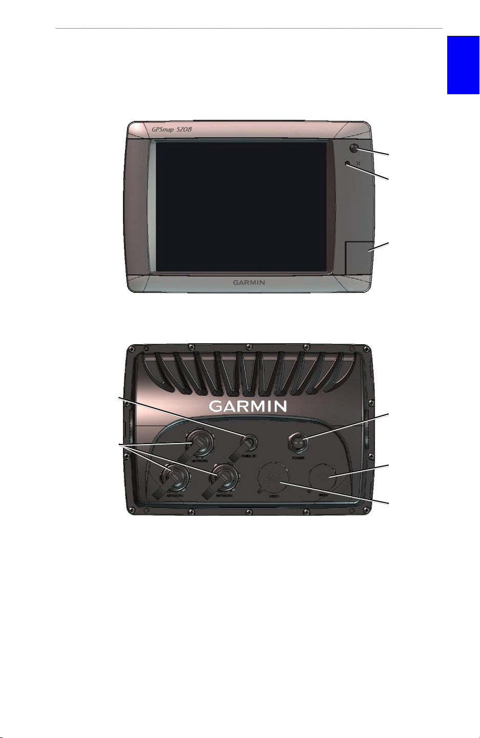
Front and Rear Panels
Power key
Automatic
backlight
sensor
SD card slot
GPSMAP 5208 shown - Front
started
GettInG
NMEA 2000
Network
Power
NMEA
Video
GPSMAP 5208 shown - Back
GPSMAP 5000 Series Owner’s Manual 1
Page 8
GettInG Started
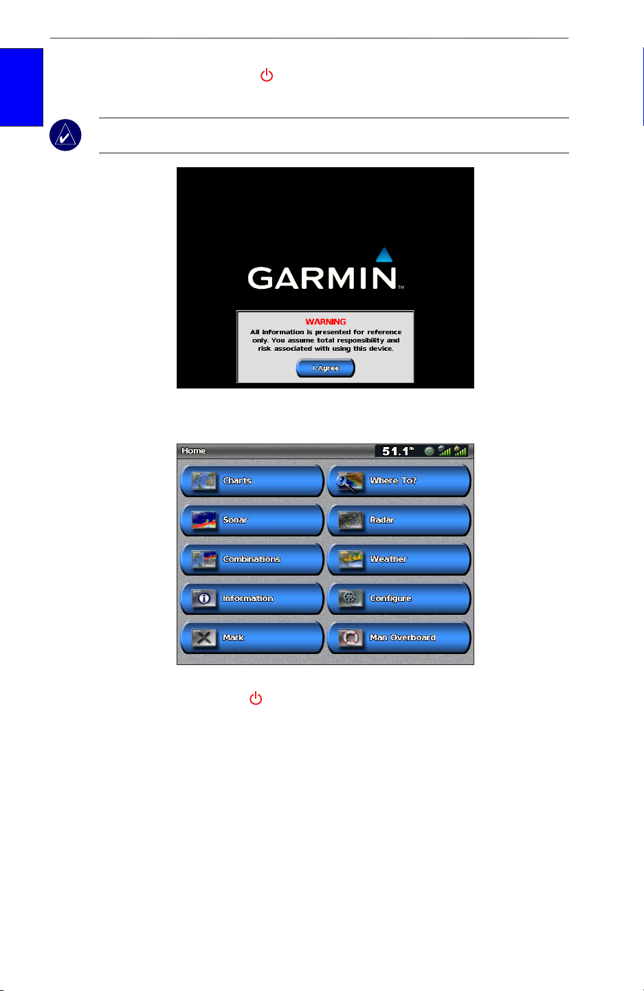
Power/Backlight
To turn the unit on, press and release the Power key. When the Warning screen appears, touch
I Agree to open the Home screen.
GettInG
started
NOTE: The rst time you power on your unit, you must go through a setup sequence. See page 61
for details.
Warning Screen
Home Screen
To turn the unit off, press and hold the Power key.
2 GPSMAP 5000 Series Owner’s Manual
Page 9
GettInG Started
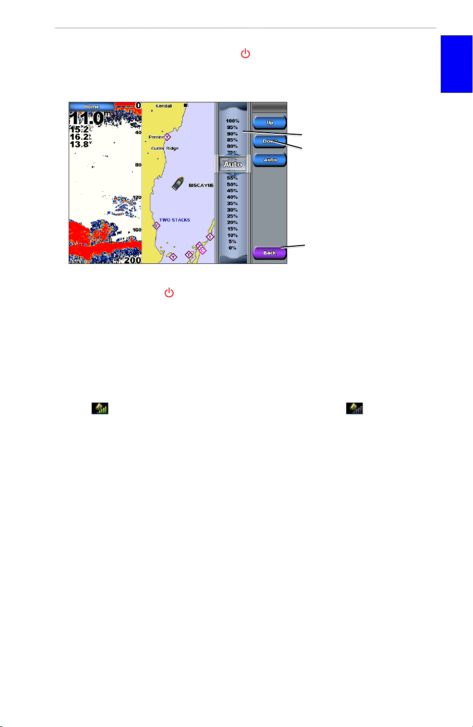
Adjusting the Backlight
1. While the unit is on, press and release the Power key.
2. Touch Backlight.
3. To allow the unit to automatically adjust the backlight based on ambient light, touch Auto.
To manually adjust the backlight,
either touch and drag the
brightness bar or touch and hold
Up or Down.
To return to the previous screen,
touch Back.
Adjusting the Color Mode
1. Press and release the Power key.
2. Touch Color Mode.
3. Touch Day Colors, Night Colors, or Auto.
started
GettInG
Acquiring GPS Satellite Signals
When you turn the unit on, the GPS receiver must collect satellite data and establish its current
location.
When the unit acquires satellite signals, the signal strength bars at the top of the Home screen
are green . When the unit loses satellite signals, the green bars disappear and a ashing
question mark is indicated on the boat icon (on the chart screen).
For more information about GPS, visit the Garmin Web site at www.garmin.com/aboutGPS.
Inserting and Removing SD Cards
Your unit supports SD (Secure Digital) cards. Insert optional BlueChart® g2 Vision™ SD cards to
view high-resolution satellite imagery, and aerial reference photos of ports, harbors, marinas and
other points of interest. Insert blank SD cards to transfer data such as waypoints, routes, and tracks
to another compatible Garmin unit or a computer. The SD card slot is located on the bottom-right
corner of the unit.
GPSMAP 5000 Series Owner’s Manual 3
Page 10
GettInG Started
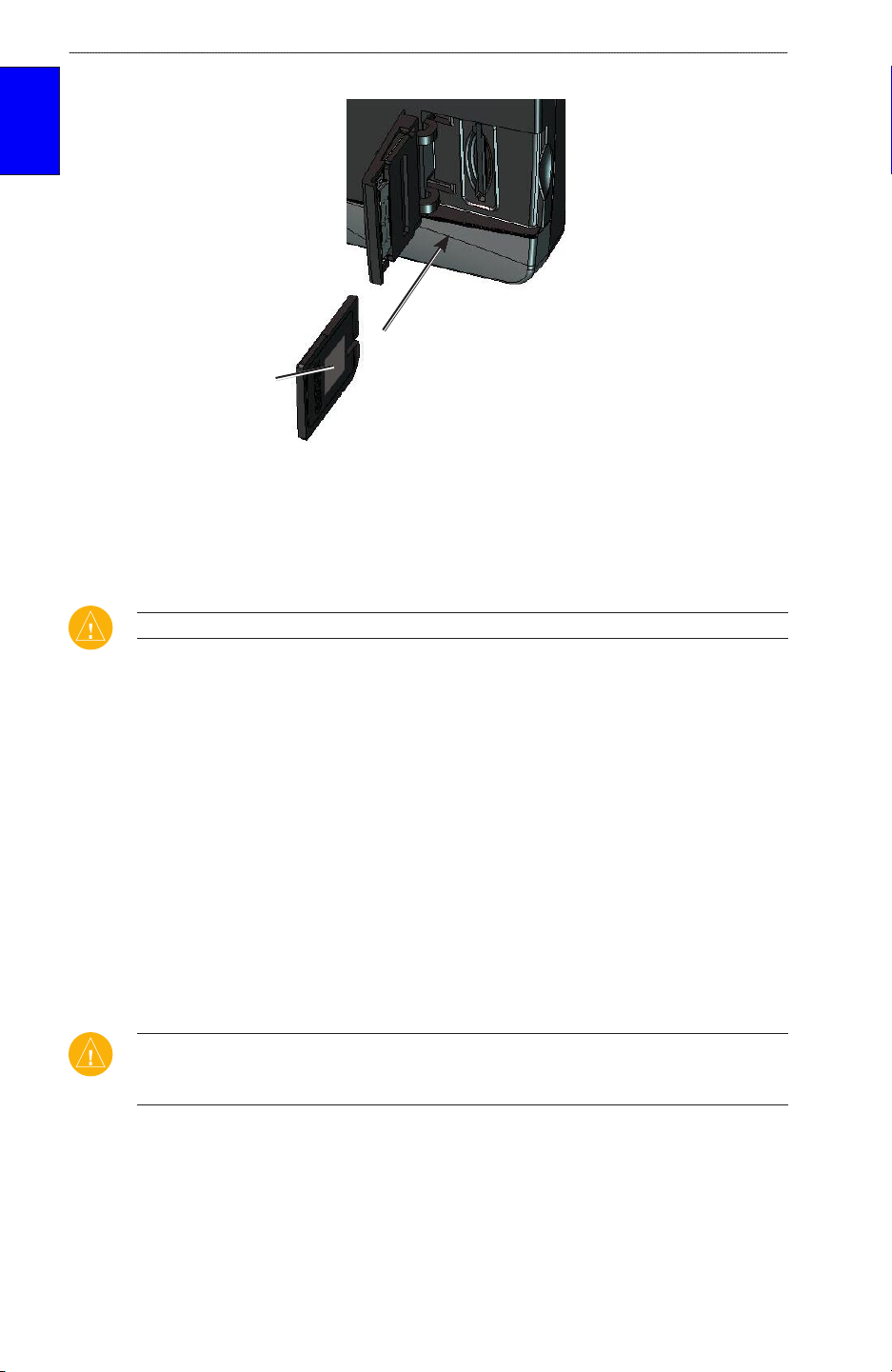
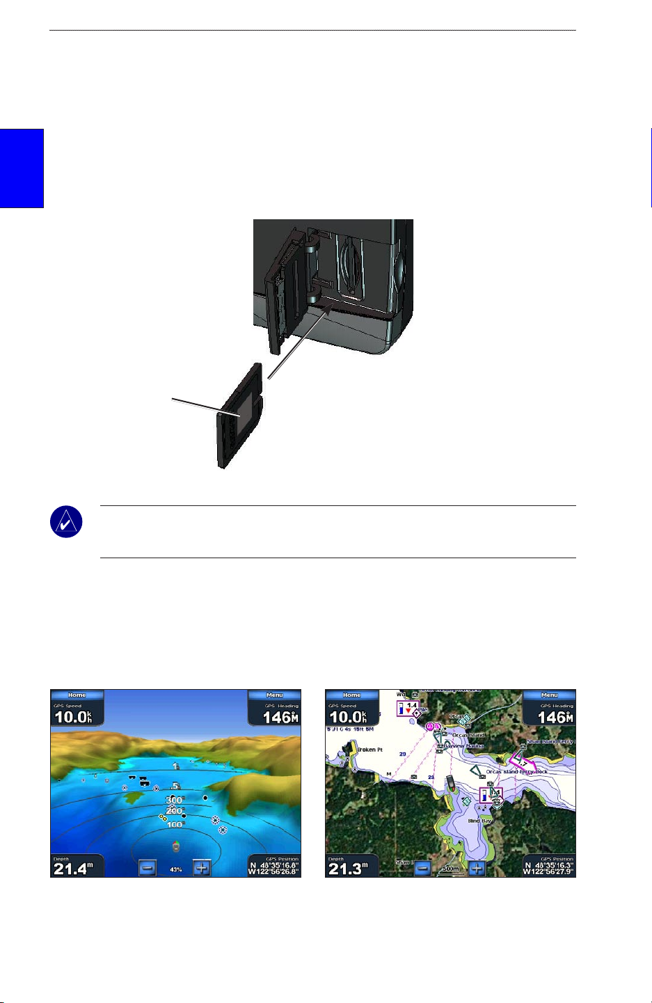
To insert the SD card, open the access door and press it in until it clicks.
GettInG
started
Card label
GPSMAP 5008 or 5208
To remove the SD card, press in on the card. The card pops out.
Restoring Factory Settings
You can restore your unit to the original factory settings.
CAUTION: This procedure deletes any information you have entered.
To restore factory settings:
1. From the Home screen, touch Congure > System > System Information > Factory
Settings > Reset.
2. Touch OK to restore all factory settings or touch Cancel.
Viewing System Information
You can view your unit’s software version, basemap (built-in map) version, unit ID number, and
your XM WX weather radio ID (if available). You may need this information to update the system
software or purchase additional map data information.
From the Home screen, touch Congure > System > System Information.
Using the Simulator Mode
Simulator mode turns the GPS receiver off for use indoors or for practice. The unit does not track
satellites in simulator mode.
CAUTION: Do not try to navigate using simulator mode because the GPS receiver is turned off.
Any satellite signal strength bars shown are only simulations and do not represent the strength of
actual satellite signals.
To turn on Simulator Mode
1. From the Home screen touch Congure > System > Simulator.
2. Touch On to turn the simulator mode on. Touch Setup to set speed, track control, position,
simulator time, and simulator date.
4 GPSMAP 5000 Series Owner’s Manual
Page 11
GettInG Started
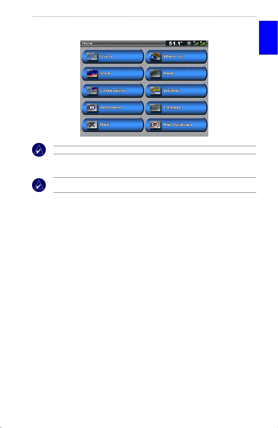
Understanding the Home Screen
Use the Home screen to access all other screens.
NOTE: Options on this screen vary based on the unit type and optional connected network devices.
Charts—provides Navigation, Mariner’s Eye 3D, Fish Eye 3D, Fishing Chart, and Radar
•
Overlay charts (page 6).
NOTE: Fish Eye 3D, and Fishing Charts are available only if you use a BlueChart g2 Vision SD
card.
started
GettInG
Sonar—provides sonar information (only available if the unit is connected to a Garmin sonar
•
module) (page 48).
Combinations—sets up the screen to view a chart, sonar, radar, and video in a 2, 3, or 4-eld
•
split screen (page 19).
Information—shows information including tides, currents, celestial data, user data,
•
information about other boats, gauges, and video (page 29).
Mark—marks, edits, or deletes your current location as a waypoint or Man Overboard
•
(page 24).
Where To—provides navigation features (page 21).
•
Radar—sets up and displays radar (only available if the unit is connected to a radar module)
•
(page 43).
Weather—sets up and displays various weather parameters, including precipitation, forecast,
•
shing, sea conditions, and visibility (only available if the unit is connected to a weather
module and you have an XM subscription) (page 52).
Congure—allows you to view and edit your unit and system settings (page 34).
•
Man Overboard—navigate to a Man Overboard location (page 24).
•
GPSMAP 5000 Series Owner’s Manual 5
Page 12
uSInG chartS
usInG charts
The GPSMAP 5008 and 5012 units have a basic worldwide imagery map, and the GPSMAP 5208
and 5212 have built-in detailed BlueChart g2 offshore cartography for US waters.
Navigation Chart—shows all relevant navigation data available on your preloaded maps,
•
including buoys, lights, cables, depth soundings, marinas, and tide stations in an overhead
usInG
charts
view.
Mariner’s Eye—provides an angled perspective from above and behind your boat for a visual
•
navigation aid.
NOTE: If you are using a GPSMAP 5008 or 5012, you must insert an optional BlueChart g2 Vision
preprogrammed SD card to view detailed Navigation and Mariner’s Eye charts.
Fishing Charts and Fish Eye 3D views are available when using optional Blue Chart g2 Vision
preprogrammed SD cards (See page 11).
Fishing Chart—removes navigational data from the chart, while enhancing bottom contours
•
for depth recognition.
Fish Eye 3D—provides an underwater view that visually represents the sea oor according to
•
the chart’s information.
The unit selectively displays navigation data after you select the type of navigation you want.
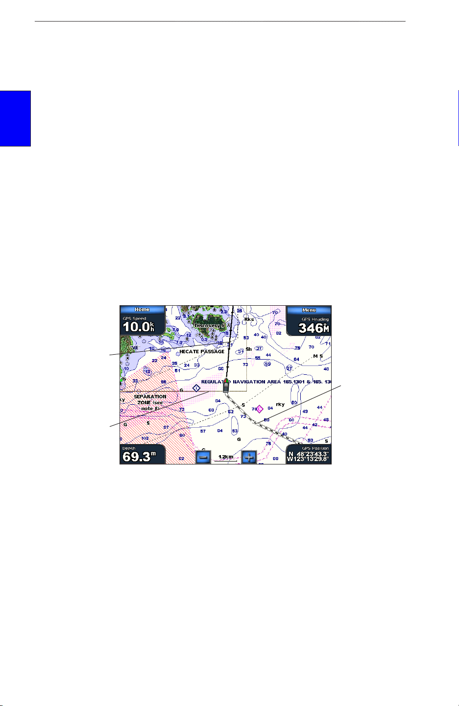
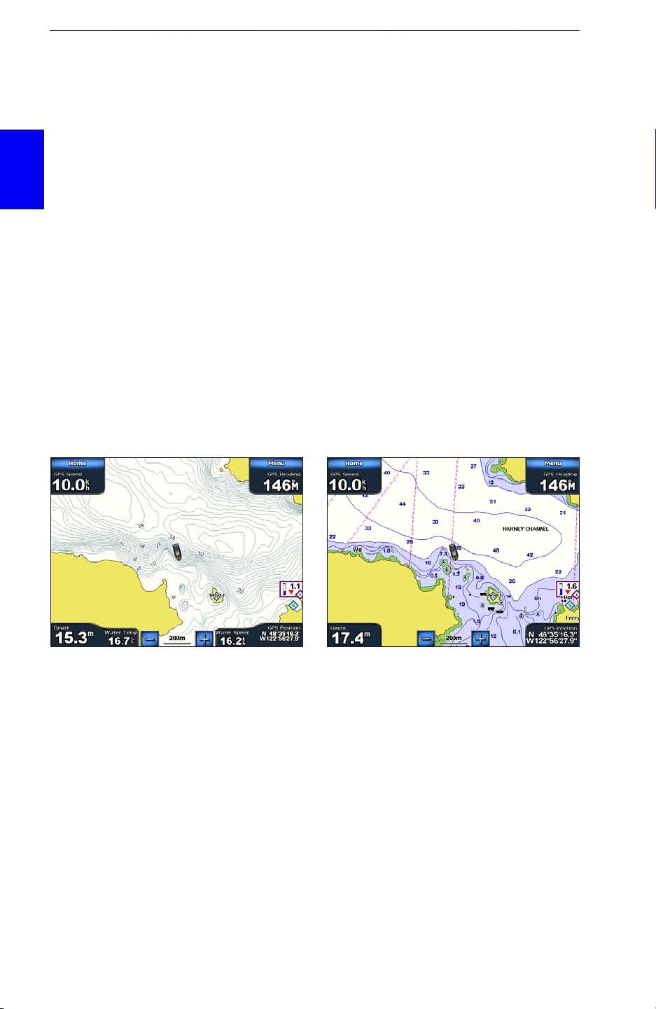
Using the Navigation Chart
Use the navigation chart as a navigational aid to plan your course and view map information.
NOTE: For GPSMAP 5008 or 5012 units, you must insert an optional BlueChart g2 Vision
preprogrammed SD card for your region to view detailed navigation charts.
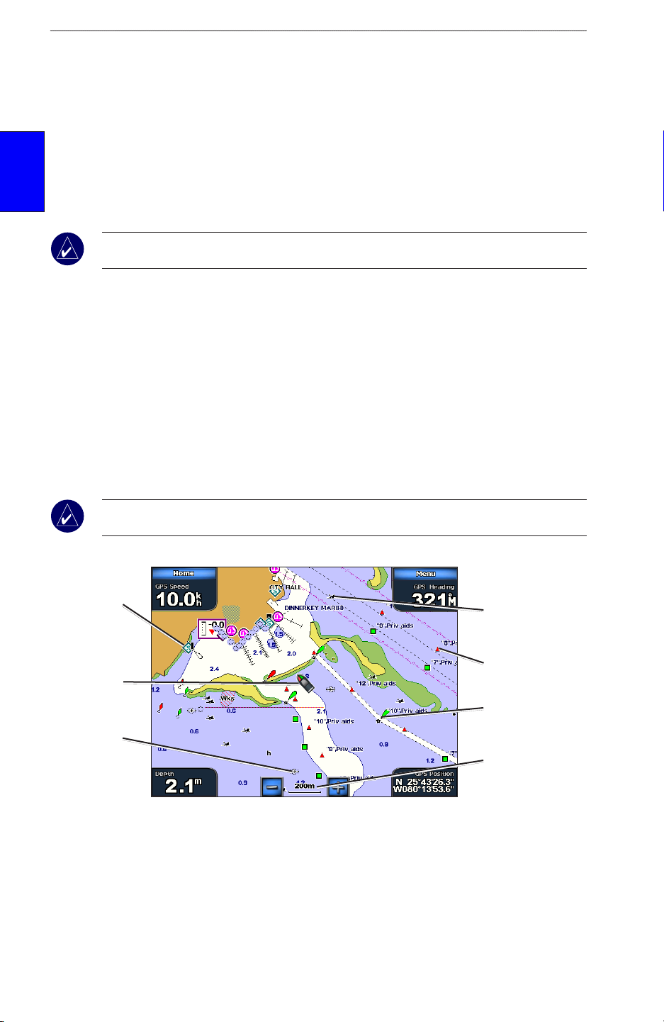
To access a navigation chart, from the Home screen, touch Charts > Navigation Chart.
Marine
services
Your boat
Submerged
wreck
Navigation Chart on a GPSMAP 5208
Navigation Chart Settings
To access additional settings or options for the navigation chart, touch Menu.
Exposed
wreck
Beacon
Buoy
Zoom scale
Weather—turns the NEXRAD weather overlay on or off. Only available when connected to a
Garmin XM network device. See page 52 for more information.
6 GPSMAP 5000 Series Owner’s Manual
Page 13
uSInG chartS
Overlay Numbers—control how charting numbers appear on the screen. Choose to show or hide
the numbers by category. Touch Auto to show navigation, shing, and sailing numbers. When set to
Auto, the overlay numbers appear only when that category is active.
Cruising: GPS position, GPS heading, GPS speed, and depth. Depth is only available if
•
connected to a sonar unit (page 48).
Navigation: GPS position, distance, arrival (time), bearing (to destination), GPS heading, and
•
GPS speed. These numbers appear only when navigating to a destination (page 21).
Fishing: GPS position, depth, water temp, and water speed. Depth, temp, and speed are only
•
available when connected to a sonar unit (page 48).
•
Sailing:
GPS position, waypoint velocity made good (VMG), wind speed, wind direction,
water speed, and depth. Wind speed and direction are only available when connected to a
NMEA 0183 wind sensor. Water speed and depth are only available when connected to a
sonar unit. If you have a wind sensor, setting the sailing overlay numbers to Auto places an
indicator around the boat icon on the navigation chart to represent wind speed and direction.
Chart Setup
—customizes the navigation chart. See page 14.
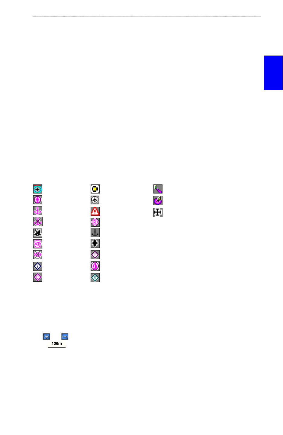
Understanding Chart Data
BlueChart g2 and BlueChart g2 Vision charts use graphic symbols to denote map features. Some
common symbols you might see include, but are not limited to, the following:*
charts
usInG
Dangerous Rock Exposed Rock Beacon
Pilot Boarding Area Airport/Seaplane Base Buoy
Anchorage Berth Precautionary Area Church
Anchoring Prohibited Radio Report Point
Exposed Wreck Recommended Anchorage
Fishing Harbor Rescue Station
Fishing Prohibited Tide Station
Information Yacht Harbor
Current Station Marine Services
*Some symbols might appear differently on your Garmin unit.
Other features common to most charts include depth contour lines (with deep water represented in
white), intertidal zones, spot soundings (as depicted on the original paper chart), navigational aids
and symbols, and obstructions and cable areas.
Zooming In and Out on the Map
The and keys control the zoom level, indicated by the scale at the bottom of the navigation
chart ( ). The bar under the number represents that distance on the map.
Navigating to a Point
To navigate to a point on the chart:
1. From the Home screen, touch Charts.
2. Touch Navigation Chart, Fishing Chart, or Radar Overlay.
3. Touch the point on the chart where you want to go.
GPSMAP 5000 Series Owner’s Manual 7
Page 14
uSInG chartS
4. Touch Navigate To.
5. Touch Go To or Guide To (available when using a preprogrammed BlueChart g2 Vision card
to use Auto Guidance, page 27).
6. Follow the colored line on the screen to the destination.
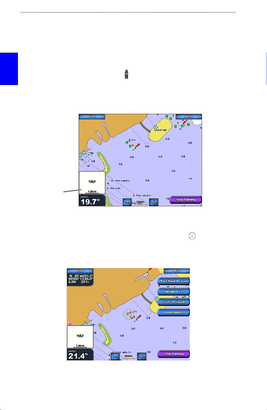
Panning the Navigation Chart
Touch and drag the Navigation screen to pan away from your current location, and scroll to other
areas on the navigation chart. The position icon ( ) stays at your present location. If the position
usInG
charts
icon leaves the map when you pan, an inset map appears on the left of the screen so you can keep
track of your current position.
As you pan, the Depth reading of your current location remains in the lower-left corner of the screen
(if your unit is connected to a sonar device through a Garmin Marine Network).
Inset map
Navigation Chart on a GPSMAP 5208
To stop panning and return the screen to your boat’s current location, touch Stop Panning.
When you touch a point on the Navigation screen without dragging, a pointer ( ) appears at that
spot, and a list of options appear along the right side. These options change, depending on the point
you touched. Touch a button to access that option.
You can change the position of the pointer by touching and dragging it to the desired location.
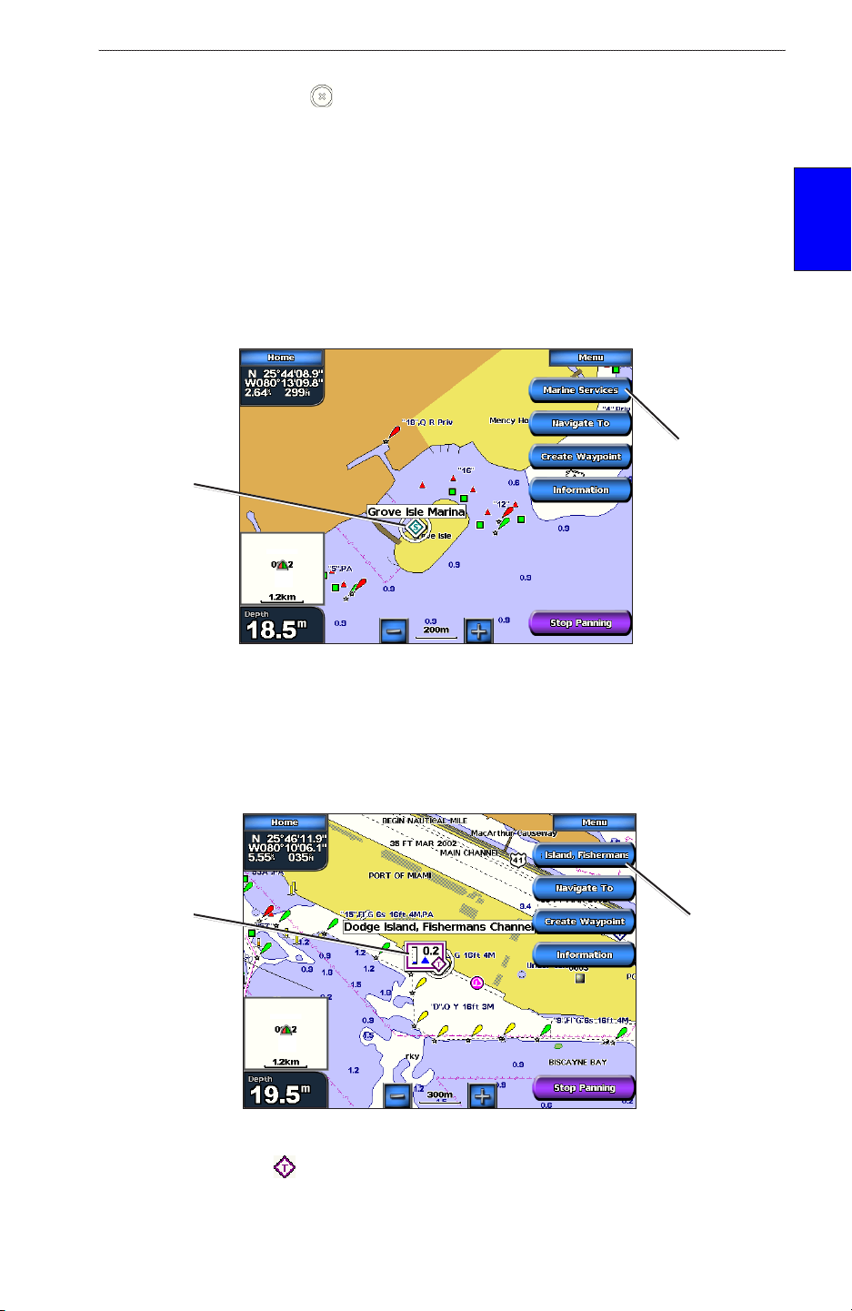
Review—(does not appear if the pointer is not near an object - if the pointer is near only one object,
its name appears instead of Review.) Touch this button to view details of the objects in the vicinity
8 GPSMAP 5000 Series Owner’s Manual
Page 15
uSInG chartS
of the pointer. If the point is near several objects and you touch Review, you are presented with a list
of the objects near the pointer ( ).
Navigate To—allows you to navigate to the selected location (page 7).
Create Waypoint—marks a waypoint at the selected location (page 23).
Information—allows you to view tide stations (page 29), current stations (page 29), celestial (page
30), weather information (if available, see page 52), or chart information near the pointer.
Accessing Additional Object Information
Touch an item on the screen to view information about map items, waypoints, and charts. Touch the
button with the item’s name on it to get additional information about the location.
Additional
Highlighted
object
Object Selected on a GPSMAP 5208
object
information
charts
usInG
Viewing Tide Station Information
Tide station information appears on the chart with a detailed icon showing the relevant tide level.
You can view an in-depth graph for a tide station to help predict the tide level at different times or
different days.
Relevant tide
level
Tide Station Selected on a GPSMAP 5208
Touch a tide station icon ( ), then touch the button with the station name (or Review if more than
one item is in the vicinity) for a detailed tide graph. For more information about tides, see page 29.
Detailed
tide station
information
GPSMAP 5000 Series Owner’s Manual 9
Page 16
uSInG chartS
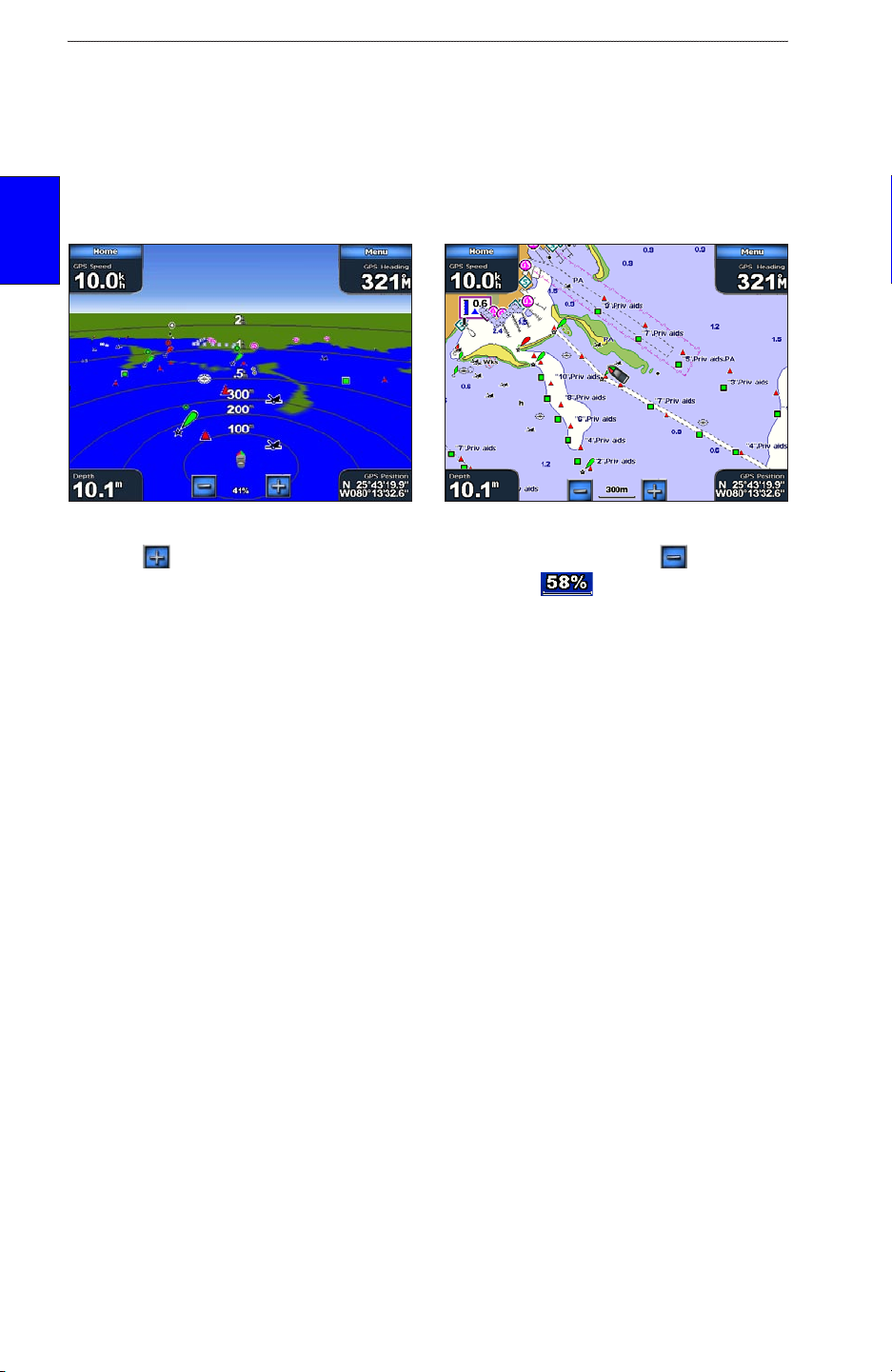
Using Mariner’s Eye
Mariner’s Eye provides an angled perspective from above and behind the boat (according to
your course), and provides a visual navigation aid. This view is helpful when navigating tricky
shoals, reefs, bridges, or channels, and is benecial when trying to identify entry and exit routes in
unfamiliar harbors or anchorages.
To access the Mariner’s Eye screen from the Home screen, touch Charts > Mariner’s Eye.
usInG
charts
Mariner’s Eye Navigation Chart
Touch the button to view closer to your boat and lower to the water. Touch the button to
move the view away from the boat. This is indicated by the scale ( ) at the bottom of the
screen.
Mariner’s Eye Settings
To access additional settings or options from the Mariner’s Eye screen, touch Menu.
Rings—toggles the range rings on or off.
Tracks—turns the visible tracklog on or off. The unit continues to record tracks if you turn this
setting off, but they are hidden from view.
Safe Depth
with an optional BlueChart g2 Vision SD card.
Lane Width
navigation. This setting does not affect routes (Route To) or automatic guidance (Guide To).
—adjusts the depth at which red indicates shallow water. This feature is only available
—adjusts the width of the course line drawn on the screen when navigating using Go To
10 GPSMAP 5000 Series Owner’s Manual
Page 17
uSInG chartS
Show Radar—If you are connected to a Garmin Marine Radar through the Garmin Marine
Network, you can overlay your radar readings on the Mariner’s Eye screen.
Mariner’s Eye With Radar Information
Overlay Numbers—show or hide cruising, navigation, shing, and sailing numbers as on the
navigation chart.
Using BlueChart g2 Vision
Optional BlueChart g2 Vision preprogrammed SD cards allow you to get the most out of your unit.
In addition to detailed marine charting, BlueChart g2 Vision has the following features:
charts
usInG
Mariner’s Eye 3D—provides an angled perspective from above and behind the boat for a
•
visual, three-dimensional navigation aid. The BlueChart g2 Vision Mariner’s Eye 3D is more
detailed than the preloaded data.
Fish Eye 3D—shows an underwater, three-dimensional view that visually represents the
•
sea oor according to the chart’s information.
Fishing Charts—displays the chart with enhanced bottom contours and without navigational
•
data. This chart works best for offshore deep-sea shing.
•
High Resolution Satellite Imagery
view of the land and water on the Navigation chart.
Aerial Photos—displays marinas and other navigationally signicant aerial photos to help
•
you visualize your surroundings.
Detailed Roads and POI data—displays roads, restaurants, and other points of interest
•
(POIs) along the shore.
Current Data—provides current station information.
•
Auto Guidance—uses the specied boat safe depth and chart data to determine the best
•
course to your destination.
—provides high resolution satellite images for a realistic
GPSMAP 5000 Series Owner’s Manual 11
Page 18
uSInG chartS
Using the SD Card
You can insert or remove a BlueChart g2 Vision SD card while your Garmin GPS unit is on or off.
Insert the SD card into the open SD card slot on your Garmin GPS unit and press in until it clicks.
Press in again to eject the SD card.
BlueChart g2 Vision SD cards are not waterproof. When you are not using the card, keep it in the
original packaging for safekeeping and store it away from exposure to sun and rain.
usInG
BlueChart g2 Vision SD cards are susceptible to damage from static electricity. In low humidity
charts
environments, you should ground yourself on a large metal object before handling the card.
Card label
GPSMAP 5008 or 5208
NOTE: BlueChart g2 Vision data cannot be transferred from the SD card to your computer for
backup or viewing purposes. You can use the SD card only on BlueChart g2 Vision compatible
Garmin GPS units.
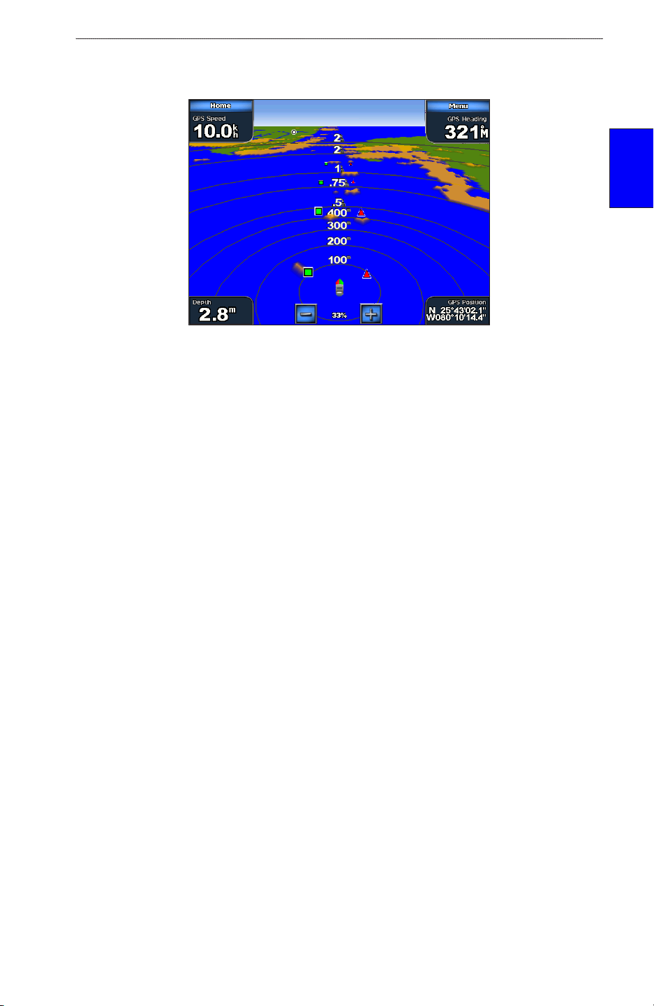
Using Mariner’s Eye 3D
A BlueChart g2 Vision SD card offers Mariner’s Eye 3D, which provides a detailed,
three-dimensional angled perspective from above and behind the boat (according to your course) and
provides a visual navigation aid. This view is helpful when navigating tricky shoals, reefs, bridges,
or channels, and when trying to identify entry and exit routes in unfamiliar harbors or anchorages.
Mariner’s Eye 3D Navigation Chart
12 GPSMAP 5000 Series Owner’s Manual
Page 19
uSInG chartS
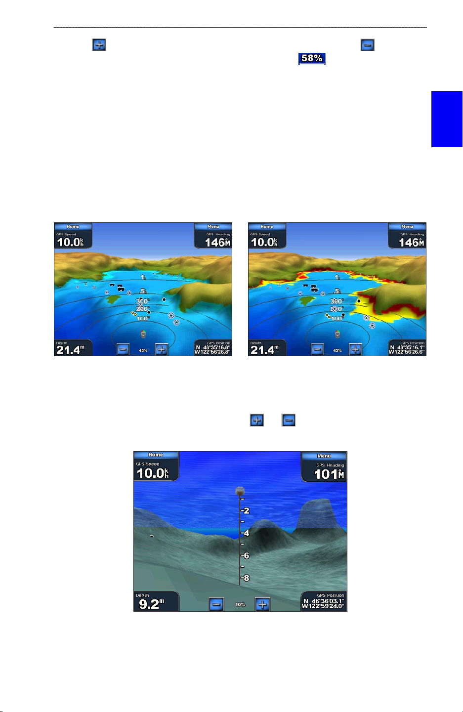
Touch the button to view closer to your boat and lower to the water. Touch the button to
move the view away from the boat. This is indicated by the scale ( ) at the bottom of the
screen.
Mariner’s Eye 3D Settings
charts
To access additional settings or options from the Mariner’s Eye 3D screen, touch Menu. The options
and additional settings are the same as the Mariner’s Eye screen (page 10), with the exception of
Colors.
Colors —choose between Normal (Default), Water Hazard, and All Hazard. The Normal setting
shows the land as seen from the water. The Water Hazard settings indicates shallow water and land
with a color scale. Blue indicates deep water, yellow is shallow water, and red is very shallow. The
Water Hazard setting indicates land in green, and the All Hazard setting uses the same color scale,
but shows land as dark red.
Mariner’s Eye 3D, Normal Colors Mariner’s Eye 3D, Hazard Colors
usInG
Using Fish Eye 3D
Using the depth contour lines of the BlueChart g2 Vision cartography, Fish Eye 3D provides an
underwater view of the sea oor or lake bottom. The and buttons adjust the view in the
same way as the Mariner’s Eye 3D.
Fish Eye 3D
GPSMAP 5000 Series Owner’s Manual 13
Page 20
uSInG chartS
Fish Eye 3D Settings
To access additional settings or options for the Fish Eye 3D screen, touch MENU.
Sonar Cone
Sonar Data
—turn a cone on or off that shows the area covered by your transducer.
—visually show the sonar readings received by your transducer for the best combination
of sonar and mapping. The setting is either on or off.
Tracks—turn the track log on or off.
usInG
charts
Overlay Numbers—show or hide cruising, navigation, or shing numbers just as on the navigation
chart (page 7).
Changing the Chart Settings
To change chart settings from the Home screen, touch Charts > Chart Setup, or touch Menu >
Chart Setup while viewing the navigation chart.
Orientation—change the perspective of the map display:
North Up
•
•
Track Up
•
Course Up
appears vertically on the screen if it is shown.
Heading line
—sets the top of the map display to a north heading.
—sets the map display to the current track heading.
—sets the map so the direction of navigation is always up. The heading line
Track
Chart border
Heading Line—draws an extension from the bow of the boat in the direction of travel.
Off—turns off the heading line.
•
Distance—sets the distance to the end of the heading line.
•
Time—sets the amount of time until you reach the end of the heading line.
•
Chart Borders—turns on chart borders if you are using a BlueChart g2 Vision SD card and you
want to see what area the maps cover.
Tracks—turns the track log on or off (page 15).
Inset Map—turns the inset map on or off when panning (page 8).
Appearance—customizes the appearance of your navigation chart.
Detail—adjusts the amount of detail shown on the map.
•
Photos—sets the high resolution satellite images to on, off, land only, or blend (page 17).
•
14 GPSMAP 5000 Series Owner’s Manual
Page 21
uSInG chartS
Spot Depth—turns on spot soundings and sets a dangerous depth.
•
•
Light Sectors
•
Symbols
•
Symbol Size
—adjusts the drawing of light sectors on the map.
—sets the navaid symbol set (NOAA or IALA).
—adjusts the size of the symbols shown on the map.
Using Tracks
A track is a recording of your path. The track currently being recorded is the active track. An active
track can be saved.
To turn the track log on:
From the Navigation chart, touch Menu > Chart Setup > Tracks > On. A trailing line on the chart
indicates your track.
charts
usInG
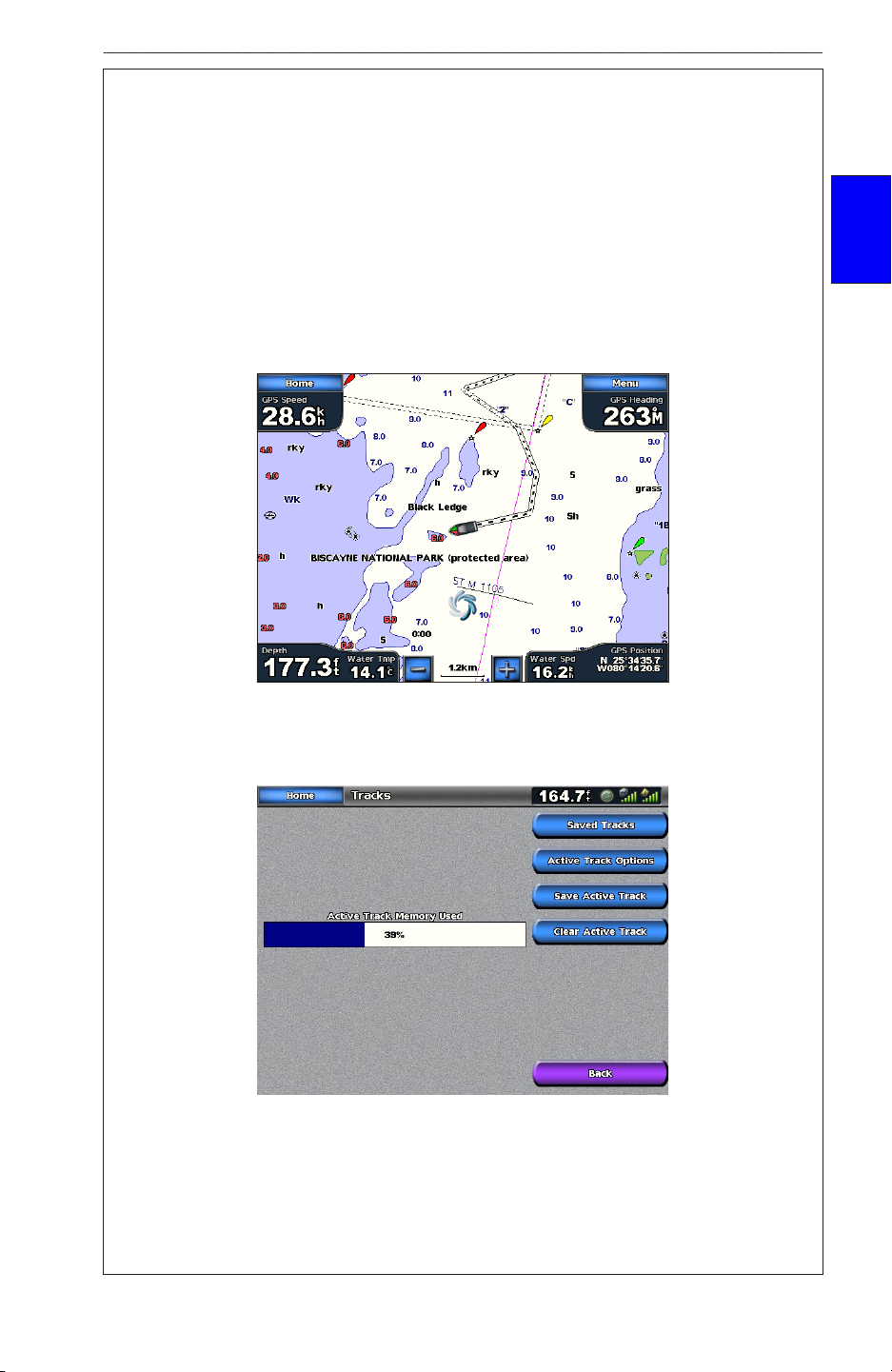
To save or clear the active track:
1. From the Home screen, touch Information > User Data > Tracks.
2. Touch Save Active Track to save the track; touch Clear Active Track to clear it.
To set active Track Options:
From the Home screen, touch Information > User Data > Tracks > Active Track Options.
Record Mode—select Off, Fill, or Wrap
•
Off—no track log is recorded
•
Fill—a track log is recorded until the track memory is full
•
GPSMAP 5000 Series Owner’s Manual 15
Page 22
uSInG chartS
Wrap—continuously records the track log, wrapping through the available memory
•
(replacing the oldest track data with new data).
Interval—denes the frequency at which the track plot is recorded. Recording more frequent
•
plots is more accurate, but lls the track log faster.
Interval—sets whether the interval is determined by distance, time, or resolution. (Press
•
Change to set the quantity.)
Distance—records the track based on a distance between points.
usInG
charts
•
Time—records the track based on a time interval.
•
Resolution—records the track plot based on a variance from your course. This setting is
•
recommended for the most efcient use of memory. The distance value is the maximum
error allowed from the true course before recording a track point.
Change—Sets the value of the interval.
•
Color—sets the color of the track plot.
•
To edit or delete a saved track:
1. From the Home screen, touch Information > User Data > Tracks > Saved Tracks.
2. Touch the track you want to edit or delete.
3. Touch Edit Track to change the name or color of the track or to delete it.
Using Fishing Charts
Use the shing chart for a detailed view of the bottom contours and depth soundings on the chart.
Fishing Chart Navigation Chart
The shing chart uses detailed bathymetric data on a preprogrammed BlueChart g2 Vision SD card,
and is best for offshore deep-sea shing.
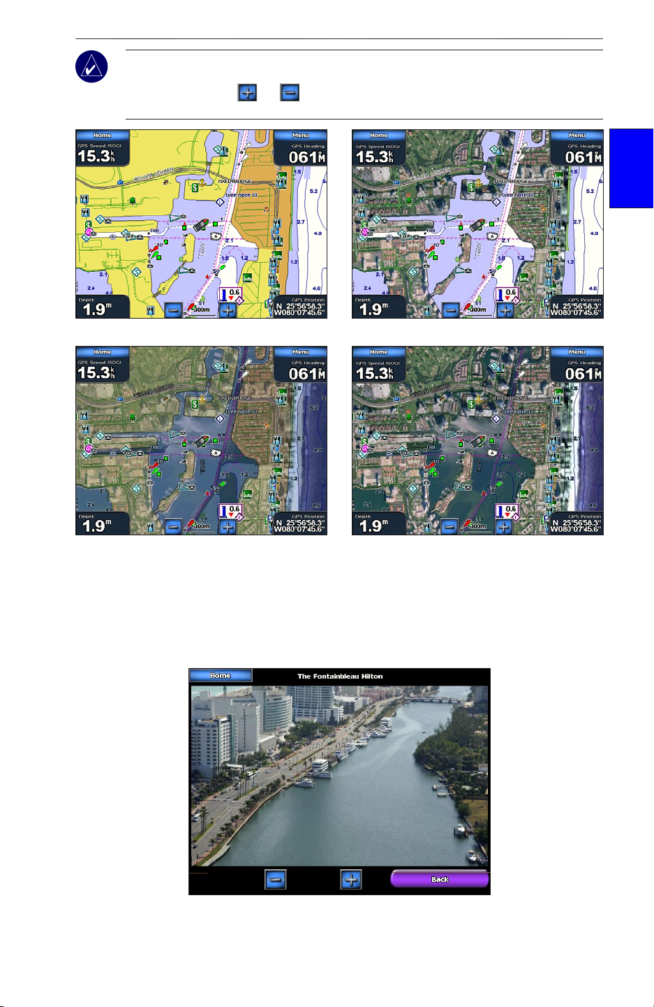
Enabling High ResolutionHigh Resolution Satellite Imagery
You can overlay high-resolution satellite images on the land, sea, or both portions of the Navigation
chart when using a preprogrammed BlueChart g2 Vision SD card.
To enable satellite imagery:
1. While viewing the Navigation Chart, touch Menu > Chart Setup > Appearance > Photos.
2. Touch one of the following:
Off—standard chart information is shown on the map.
•
Land Only—standard chart information is shown on water with photos overlaying the land.
•
Blend—photos overlay both the water and the land at a specied opacity. The higher you
•
set the percentage, the more the satellite photos cover both land and water.
16 GPSMAP 5000 Series Owner’s Manual
Page 23
uSInG chartS
NOTE: When enabled, the high resolution satellite images are only present at lower zoom levels.
If you cannot see the high resolution images in your BlueChart g2 Vision region, either zoom in
further by touching the and buttons, or set the detail level higher by touching Chart Setup
> Appearance > Detail.
charts
usInG
Photo Overlay Off Land Only Photo Overlay
Blend at 50%
Blend at 100%
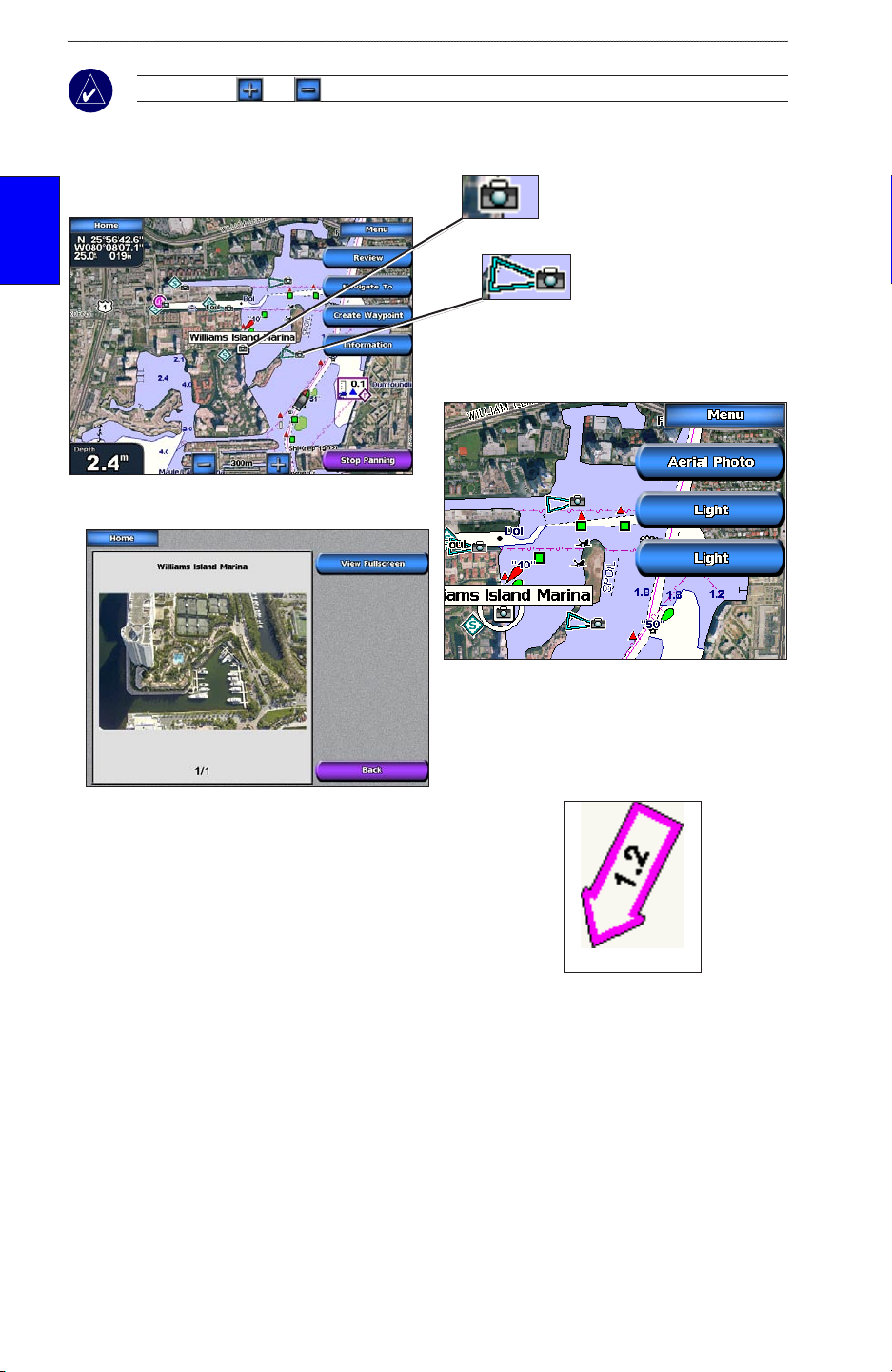
Viewing Aerial Photos
Preprogrammed BlueChart g2 Vision SD cards contain aerial photographs of many landmarks,
marinas, and harbors. Use these photos to help acquaint yourself with a marina or harbor prior to
arrival.
Aerial Photo
GPSMAP 5000 Series Owner’s Manual 17
Page 24
uSInG chartS
Current Station iconCurrent Station icon
NOTE: Touch and to zoom in and out while viewing the aerial photo on the full screen.
To access aerial photos from the navigation chart:
Touch a camera icon, and
➊
then touch Review.
usInG
charts
➋
Touch View Fullscreen.
➌
Overhead
Perspective
Touch Aerial Photo.
Viewing Current Station InformationCurrent Station Information
If current stations are available in your g2 Vision region,
they appear on the navigation chart as a highlighted arrow.
This detailed icon shows the current’s speed and direction at
a glance.
Detailed Road and POI Data
BlueChart g2 Vision contains detailed road and POI data, which includes highly detailed coastal
roads and points of interest (POIs) such as restaurants, lodging, local attractions and more. For
instructions on searching for and navigating to these POIs, see the “Where To” section beginning on
page 21.
Using Automatic Guidance
Automatic Guidance automatically creates and suggests passage based on available BlueChart g2
Vision chart information. See page 38 for instructions on setting up Automatic Guidance for your
boat. See page 27 to use Automatic Guidance.
18 GPSMAP 5000 Series Owner’s Manual
Page 25
uSInG combInatIonS
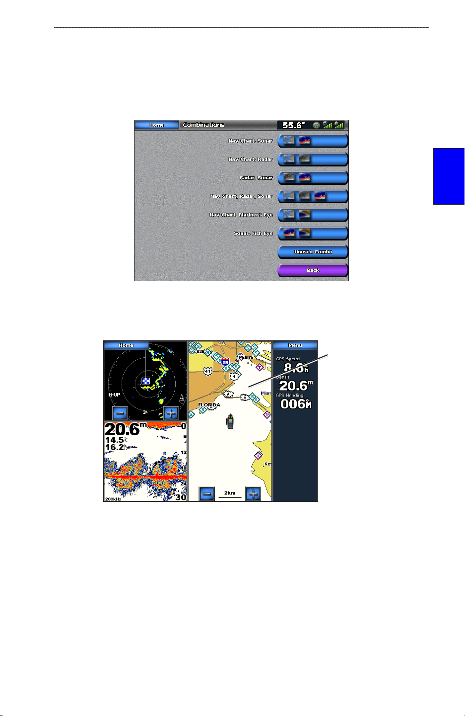
usInG combInatIons
Use the Combinations screen to view a combination of different screens at the same time. The
number of options available on the Combinations screen depends on the optional network devices
you have connected to your GPSMAP 5000 series unit and if you are using an optional BlueChart g2
Vision SD card. You can choose to combine two, three, or four screens.
combInatIons
Combinations Screen
When you choose Combinations from the Home screen, you are presented with a list of possible
screen combinations to choose from. Once you select a combination, you can customize it.
usInG
Focus screen
Radar, Sonar, and Navigation Combination
When viewing three combined screens, one is larger than the rest, and acts as the screen in focus.
To switch the focus screen, touch Menu > Change Combination. The charts are numbered, with a
corresponding button on the right of the screen. Touch the numbered button of the display you want
to change and then touch the type of screen you want to appear in that window. For a description of
the settings for each screen, see the corresponding section in this manual.
GPSMAP 5000 Series Owner’s Manual 19
Page 26

uSInG combInatIonS
To customize the screen combinations:
1. While viewing a combinations screen, touch Menu > Change Combination.
OR
From the Home screen, touch Combinations > Unused Combo (if one is available).
Combination
Combination
usInG
combInatIons
2. Touch Num Functions to change the number of combination screens (1-4). Touch Data Bar
3. Touch Done.
Select the number of
combination screens
screen 1
screen 2
Data bar
Toggle the
data bar
Change
combination
screens
to toggle the data bar on or off. Touch a combination screen button to select the screens to
view.
NOTE: When you select the combination screens to view, you are only able to choose from
the options available to your unit. You can increase the number of screens available by using a
BlueChart g2 Vision SD card and adding network devices, such as sonar and radar.
20 GPSMAP 5000 Series Owner’s Manual
Page 27

Where to
Where to
Use the Where To option on the Home screen to search for and navigate to nearby fuel, repairs, and
other services, as well as waypoints and routes.
NOTE: You must create waypoints and routes before you can navigate to them.
You can navigate to a destination using one of three methods: Go To, Route To, or Guide To.
Go To—takes you directly to the destination.
•
Route To—creates a route from your location to a destination, allowing you to add turns to
•
the route.
Guide To—searches BlueChart g2 Vision chart data to suggest the best path to your
•
destination. You must have a BlueChart g2 Vision SD card for this option to appear.
CAUTION: Guide To does not assure obstacle and bottom clearance. For safety, always resolve any
discrepancies or questions before continuing navigation.
Navigating to a Destination
You can search for and navigate to nearby destinations including fuel, repairs, marinas, waypoints,
and routes.
To begin navigating:
1. From the Home screen, touch Where To.
2. Touch the marine service category to which you want to navigate. The unit shows the list of
the 50 nearest locations and the distance and bearing to each.
Where to
GPSMAP 5000 Series Owner’s Manual 21
Page 28

Where to
Where to
3. Touch the marine service item to which you want to navigate. A screen containing information
about the selected marine service appears.
4. Touch Navigate To.
5. Touch Go To.
OR
Touch Guide To when using a preprogrammed BlueChart g2 Vision card to use Auto
Guidance.
6. Follow the colored line on the screen to the destination.
Go To Screen
Guide To Screen (with g2 Vision Card)
To stop navigating:
From the chart, Touch Menu, and then touch Stop Navigating.
22 GPSMAP 5000 Series Owner’s Manual
Page 29

To search for a destination by name:
1. From the Home screen, touch Where To > Search by Name.
2. Touch characters to spell at least a portion of the name of your destination.
3. Touch Done to view the 50 nearest destinations that contain your search criteria.
Where to
Where to
4. Touch the desired location > Navigate To > Go To (or Route To).
Creating and Using Waypoints
You can store up to 1,500 alphanumeric waypoints with a user-dened name, symbol, depth, and
water temp for each waypoint.
To create a new waypoint:
1. From the Home screen, touch Charts > Navigation Chart.
2. Touch the location you want to designate as a waypoint. A pointer marks the waypoint.
GPSMAP 5000 Series Owner’s Manual 23
Page 30

Where to
Where to
3. Touch Create Waypoint.
4. Touch one of the following:
Edit Waypoint—designates a specic name, symbol, water depth, water temperature, or
•
position.
Delete—deletes the waypoint.
•
Navigate To—goes to the waypoint.
•
Back—returns to the navigation chart.
•
To mark your current location as a waypoint:
1. From the Home screen, touch Mark.
2. Touch Edit Waypoint to designate a specic name, symbol, water depth, water temperature,
or position. Touch Back or Home to return to the Home screen.
Edit Waypoint—designates a specic name, symbol, water depth, water temperature, or
•
position.
Delete—deletes the waypoint.
•
Man Overboard—designates the current location as a Man Overboard location.
•
Next Page/Previous Page—switches between waypoint information and the navigation
•
chart.
Back—returns to the navigation chart.
•
NOTE: Touching Mark only creates a waypoint at your present location.
To mark an MOB (Man Overboard) location:
When you mark a waypoint, you can designate it as an MOB (Man OverBoard). This marks the
point and sets a course back to the marked location. When an MOB is active, an MOB waypoint
with an international MOB symbol is created and the unit is on an active navigation to that point.
1. From the Home screen, touch Man Overboard.
2. Touch Yes to begin navigating to the MOB location.
OR
1. From the Home screen, touch Mark.
2. Touch Man Overboard.
To edit an existing waypoint on the Navigation screen:
1. Touch the waypoint on the navigation chart.
24 GPSMAP 5000 Series Owner’s Manual
Page 31

Where to
2. Touch the button for the waypoint you want to edit.
3. Touch Edit Waypoint.
4 Touch the waypoint attribute you want to change (Name, Symbol, Depth, Water Temp, or
Position).
NOTE: From the Home screen, touch Information > User Data > Waypoints to display the list of all
waypoints. Touch the waypoint you want to edit.
To move the waypoint on the navigation chart:
1. Touch the waypoint on the navigation chart.
2. Touch Review (not necessary if the waypoint is not near other waypoints or markers).
3. Touch the button for the waypoint you want to edit.
4. Touch Edit Waypoint > Position.
Where to
5. Touch Use Chart or Enter Coordinates.
6. If entering coordinates, use the screen keyboard to enter the new location for the waypoint. If
using the chart, touch the new location and then touch Move Waypoint. The waypoint moves
to the new location.
To view a list of all waypoints:
From the Home screen, touch Information > User Data > Waypoints.
To delete a waypoint or MOB:
1. From the Home screen, touch Information > User Data > Waypoints.
2. Touch the waypoint or MOB you want to delete.
3. Touch Delete.
GPSMAP 5000 Series Owner’s Manual 25
Page 32

Where to
Creating and Using Routes
You can create and store up to 20 routes, with up to 250 waypoints each.
To create a route from your present location:
1. From the Navigation Chart, touch your destination. The destination is indicated by a
pointer .
Where to
2. Touch Navigate To > Route To.
3. Touch the location where you want to make the last turn toward your destination.
4. Touch Add Turn.
5. To add additional turns, continue to touch the location where you want to make a turn (working
backward from the destination) and then touch Add Turn.
6. Touch Done to nish the route or Cancel Route to delete the route.
To create a route in another location:
1. From the Home screen, touch Information > User Data > Routes > New Route.
26 GPSMAP 5000 Series Owner’s Manual
Page 33

Where to
2. If necessary, touch and drag the screen until the route’s starting point is displayed. Touch the
route’s starting point. The starting point is indicated by the pointer .
3. Touch Add Turn.
4. Touch the location of the rst turn. Repeat until the route is complete.
Where to
5. Touch Done.
To create a route using Auto Guidance:
Auto Guidance is available with a preprogrammed BlueChart g2 Vision SD card.
1. From the Navigation chart, touch your destination.
2. Touch Navigate To > Guide To. Your route is calculated.
NOTE: To change the auto guidance path to a route, touch the end of the path and then touch
Navigate To > Route To. The auto guidance path stays on the screen, allowing you to trace it while
creating a route.
To edit or delete a route:
1. From the Home screen, touch Information > User Data > Routes.
GPSMAP 5000 Series Owner’s Manual 27
Page 34

Where to
Where to
2. Touch the route to edit.
3. Touch Edit Route. You can edit the route name, turns, or delete the route.
28 GPSMAP 5000 Series Owner’s Manual
Page 35

VIeWInG InformatIon
VIeWInG InformatIon
Use the Information screen to access information about tides, currents, celestial data, user data, other
boats, gauges, and video.
You can also select tide, current, and celestial information for a specic station directly from the
Navigation chart. Touch the desired station > Information and either Tides, Currents, Celestial, or
Chart Notes.
Viewing Tide Station Information
To view tide information from the Home screen, touch Information > Tides, then touch a tide
station from the list.
Tide station
Current tide
height
Time of next
high tide
Local time
Touch Nearby Stations to view other stations close to the one you selected. Touch Change Date >
Manual to view tide information for a different date.
Viewing Current Information
Use the Current Prediction screen to view information for currents.
To view current information from the Home screen, touch Information > Currents, then touch a
current station from the list.
InformatIon
VIeWInG
Touch Nearby Stations to view other current stations close to the one you selected. Touch Change
Date > Manual to view tide information for a different date.
GPSMAP 5000 Series Owner’s Manual 29
Page 36

VIeWInG InformatIon
To view the Current Report for the selected station, touch Show Report.
Viewing Celestial Information
Use the Celestial screen to view celestial data for sun and moon rise/set, moon phase, and
approximate sky view location of the sun and moon.
To view celestial information from the Home screen, touch Information > Celestial. Touch Change
Date > Manual to view information for a different date. Touch Change Time to view information for
a specied time on that date. Touch Moon Phase to view the moon phase at the specied date and
VIeWInG
InformatIon
time.
Viewing User Data
To view user data from the Home screen, touch Information > User Data.
Waypoints—displays a list of all saved waypoints (page 25).
•
Routes—displays a list of saved routes (page 26).
•
Tracks—displays a list of saved tracks (page 15).
•
Data Transfer—transfers waypoints, routes, and tracks to and from an SD card or other
•
chartplotters on the network.
•
Clear User Data
30 GPSMAP 5000 Series Owner’s Manual
—erases all user waypoints, routes, and tracks.
Page 37

VIeWInG InformatIon
To transfer data (waypoints, routes, tracks) to or from an SD card:
1. Insert an SD card into the SD card slot on the front of the unit.
2. From the Home screen, touch Information > User Data > Data Transfer > Card.
Complete one of the following:
Touch Save To Card to save waypoints, routes, and tracks to the SD card.
•
Touch Merge From Card to transfer data from the SD card to the unit and combine it with
•
existing GPS data.
Touch Replace From Card to overwrite items on your unit.
•
To back up data to a PC:
1. Follow steps 1 and 2 above to save the data to an SD card.
2. Insert the SD card into an SD card reader that is attached to a PC.
3. From Windows Explorer, open the Garmin\UserData folder on the SD card.
4. Copy the UserData.ADM le on the card and paste it to any location on your PC.
To restore backup data to your chartplotter:
1. Copy the UserData.ADM le from your PC to an SD card in a folder named Garmin\UserData.
2. Insert the SD card into your chartplotter.
3. From the Home screen on your chartplotter, touch Information > User Data > Data Transfer
> Card.
4. Touch Replace From Card to restore the data.
InformatIon
VIeWInG
To copy or merge MapSource data to your chartplotter:
1. Insert the SD card into your chartplotter to allow it to place a le on the SD card. This le
provides information to MapSource to format its data. This only needs to be done the rst time
you copy or merge MapSource data to your chartplotter.
2. Check your MapSource version on your PC by clicking Help > About MapSource. If the
version is older than 6.12.2, update to the most current version by clicking Help > Check for
Software Updates.
3. Insert the SD card into an SD card reader that is attached to your PC.
4. From within MapSource, click on Transfer > Send to Device.
5. From the Send to Device window, select the drive for the SD card reader and the types of
data you want to copy to your chartplotter.
6. Click Send.
7. Insert the SD card into your chartplotter.
8. From the Home screen on your chartplotter, touch Information > User Data > Data Transfer
> Card.
9. Touch Replace From Card or Merge From Card to copy or merge the data into your
chartplotter.
To transfer data to or from a network:
1. Connect the unit to a Garmin Network using the network port on the back of the unit and a
network cable.
2. From the Home screen, touch Information > User Data > Data Transfer > Network.
Complete one of the following:
Touch Clone User Data to transfer waypoints, routes, and tracks to the other chartplotters.
•
Existing data is overwritten on those chartplotters.
GPSMAP 5000 Series Owner’s Manual 31
Page 38

VIeWInG InformatIon
Touch Merge User Data to transfer data between all the chartplotters connected to the
•
network. Unique data is combined with existing data on every chartplotter.
Viewing Information on Other Boats
To view information about other boats from the Home screen, touch Information > Other Boats.
NOTE: To view information about other boats, your unit must be connected to an external AIS
(Automatic Identication System) or DSC (Digital Selective Calling) device.
AIS List—displays information about all of the boats your unit is monitoring. Touch AIS List to
view the MMSIs (Maritime Mobile Service Identities) or (if the boat is broadcasting it) names of the
AIS boats sorted by range. The boat nearest to your boat appears at the top of the list.
VIeWInG
InformatIon
DSC Log—displays a list of all DSC calls, sorted by most recent, sender, or by type (distress calls or
position reports).
View By Time—view the most recent DSC calls received, sorted and listed chronologically
•
by time and date. Calls with identical time and date information show the same information in
the list.
•
View By Sender
View By Type—view the most recent distress calls or position reports, sorted chronologically.
•
Delete All—delete all log entries
•
DSC Call List
—displays the 100 most recent calls. The DSC Call List shows the most recent call
—view an alphanumerical list of senders.
from a boat. If a second call is received from the same boat, it replaces the rst call in the Call List.
Directory—displays a list of all DSC entries. You can view by name or by MMSI. You can also add
an entry.
32 GPSMAP 5000 Series Owner’s Manual
Page 39

VIeWInG InformatIon
Viewing Gauges
Use the Gauges screen to view engine gauges in an analog or digital format.
NOTE: You must be connected to a NMEA (National Marine Electronics Association) 2000
network capable of sensing engine data to view the gauges.
To select an analog or digital screen:
1. To view the Gauges from the Home screen, touch Information > Gauges.
2. To select an analog or digital screen, touch Menu from the Gauges screen.
Touch Gauge Setup to select the number of engines (1 - 4), number of fuel tanks (1 or 2), and to
reset the odometer to zero.
NOTE: For more than two engines, you can only use the digital gauges. For one or two engines,
you can switch between analog and digital gauges.
Viewing Video
Your unit can display video if you are connected to a video source (or sources) using the supplied
video cable. See the 4000/5000 Series Installation Instructions for details.
To view video from the Home screen, touch Information > Video.
Touch Menu to setup the following:
Source—selects the video device (Video 1 or Video 2) that displays the video. If you have two
•
video sources and wish to alternate between the two, touch Alternate to dene the amount of
time each video screen appears.
Aspect—selects a standard video or one that is stretched to t the screen.
•
NOTE: The video image can not be stretched to dimensions larger than what are provided by the
video device, so it may not ll the entire screen of the 5012 or 5212 units.
InformatIon
VIeWInG
Brightness—adjusts the brightness up or down. Select Auto to allow the unit to automatically
•
adjust the brightness.
Saturation—adjusts the color saturation up or down. Select Auto to allow the unit to
•
automatically adjust the saturation.
Contrast— adjusts the contrast up or down. Select Auto to allow the unit to automatically
•
adjust the contrast.
Standard—selects the video format used by the source (PAL or NTSC). Touch Auto to let the
•
unit automatically select the source format.
GPSMAP 5000 Series Owner’s Manual 33
Page 40

confIGurInG the unIt
confIGurInG the unIt
Use the Congure screen to congure unit settings.
Conguring System Settings
To change general system settings from the Home screen, touch Congure > System.
Simulator—turn Simulator Mode on or off and set up Simulator Mode options. (If you set the unit
into a Store Demonstration mode during the initial unit setup, this setting is named Demo.)
Language—touch the desired on-screen language (English, Spanish, or French).
Beeper/Display—set Beeper options, Backlight, and Color Mode.
Beeper—touch Beeper to set when the unit makes audible sounds. The settings are Off,
•
Alarms Only (default), and Key and Alarm (keys and alarms).
Backlight—touch Backlight to adjust the intensity of the backlight or touch Auto to allow the
•
unit to automatically adjust the backlight based on ambient light.
Color Mode—touch Color Mode to select Day Colors, Night Colors, or Auto to allow the
•
unit to adjust the colors.
—view GPS satellites and turn WAAS (Wide Area Augmentation System)/EGNOS (European
GPS
Geostationary Navigation Overlay Service) on or off.
System Information
networked devices (page 41).
Event Log
the unIt
Overlay Numbers—view or edit the options for Wind (Apparent Wind or True Wind) and Next
confIGurInG
Turn numbers (Distance or Time).
—shows a list of system events. Touch the event to view additional information.
—view system information, restore factory settings, and view the status of
Changing Units of Measure
To change units of measure from the Home screen, touch Congure > Units.
System Units
Statute (mh, ft, ºF), Metric (kh, m, ºC), Nautical (kt, ft, ºF), or Custom. Touch Custom to
individually dene units of measure for:
•
•
•
•
•
•
—global setting that denes most of the individual units of measure listed below.
Depth—individually sets the units of measure for depth to Feet, Fathoms, or Meters.
Temperature—individually sets units of measure for temperature to Fahrenheit (ºF) or
Celsius (ºC).
NOTE: You must be receiving NMEA Sonar depth data or using a Garmin sounder module to view
depth and temperature information.
Distance—individually sets the units of measure for distance readings (Miles, Kilometers, or
Nautical Miles).
Speed—individually sets the units of measure for speed readings (Miles Per Hour,
Kilometers Per Hour, or Knots).
Elevation—individually sets the units of measure for elevation readings (Feet or Meters).
Volume—individually sets the units of measure for volume readings (Liters, US Gallons, or
UK Gallons).
34 GPSMAP 5000 Series Owner’s Manual
Page 41

confIGurInG the unIt
Pressure—individually sets the units of measure for gauge (kPa or psi) and atmospheric
•
(Millibars or Inches of Mercury) pressure readings.
Heading—sets the reference used in calculating heading information.
Auto Mag Var (Automatic Magnetic Variation)—automatically sets the magnetic declination
•
for your location.
True—sets true north as the heading reference.
•
Grid—sets grid north as the heading reference (000º).
•
User Mag Var—allows you to set the magnetic variation value.
•
Position Format—sets the coordinate system in which a given location reading appears. Only
change the position format if you are using a map or chart that species a different position format.
Map Datum
—sets the map datum. The default setting is WGS 84. Changing the map datum changes
the coordinate system in which the map is structured. Only change the setting if you are using a map
or chart that species a different map datum.
Time Format—sets the time format (12 hour, 24 hour, or UTC) you want for time readings.
Time Zone—sets the time zone in which you are located.
Daylight Saving Time—indicates whether you want daylight saving time Off, On, or Auto. The
auto setting changes turns daylight saving time on or off, depending on the time of year.
Conguring Communications Settings
To change the communications settings from the Home screen, touch Congure >
Communications.
Port Types—touch each port’s input/output format (NMEA Std. or NMEA High Speed) to use
when connecting your unit to external NMEA or other Garmin devices.
NMEA Std.—supports the input or output of standard NMEA 0183 data, DSC, and sonar
•
NMEA input support for the DPT, MTW, and VHW sentences.
NMEA High Speed—supports the input or output of high speed 0183 data for most AIS
•
receivers.
NMEA 0183 Setup—enable or disable NMEA 0183 output sentences for sounder, route, system,
and Garmin NMEA settings.
confIGurInG
the unIt
To enable or disable NMEA 0183 output sentences:
1. From the Home screen, touch Congure > Communications > NMEA 0183 Setup.
2. Touch a setting (Sounder, Route, System, or Garmin).
GPSMAP 5000 Series Owner’s Manual 35
Page 42

confIGurInG the unIt
3. Touch the NMEA output sentence to select on or off.
4. Touch Off to disable, or touch On to enable the 0183 NMEA output sentence.
Posn. Precision—adjusts the number of digits (Two Digits, Three Digits, or Four Digits) to the
right of the decimal point for transmission of NMEA output.
Waypoint IDs—selects how the unit outputs waypoint identiers (Names or Numbers).
Defaults—resets NMEA 0183 settings to their default settings (OK or Cancel).
NMEA 2000 Setup (optional)—provides a means of differentiating units in a NMEA 2000 network.
Device Instance is used if you have two or more of the same NMEA 2000 devices in your
•
system. For example, if you have two 5208s in your system, touch Device Instance and enter
different numbers for each device.
System Instance is used if you have two or more separate NMEA systems on your boat with
•
the unIt
confIGurInG
a gateway between the systems. If this is the case, touch System Instance and assign different
numbers to each system.
Setting Alarms
You can set the unit to sound an audible alarm when certain conditions are met. By default, all
alarms are turned off.
To set an alarm:
1. From the Home screen, touch Congure > Alarms.
2. Touch an alarm category (Navigation, Engine, System, Sonar, or Weather) and set to On or
Off. Alarms include:
Navigation - Anchor Drag, Arrival, Off Course
•
Engine - Fuel
•
System - Clock, Battery, GPS Accuracy
•
Sonar - Shallow Water, Deep Water, Water Temp, Fish
•
Weather (only if XM WX weather is available) - Marine, Tornado, Severe Storm, Flood,
•
Flash Flood
36 GPSMAP 5000 Series Owner’s Manual
Page 43

confIGurInG the unIt
3. Touch On to turn the alarm on and then use the touch screen keyboard to specify alarm
information.
Setting Navigation Alarms
To set a navigation alarm from the Home screen, touch Congure > Alarms > Navigation.
Anchor Drag—sets an alarm to sound when you exceed a specied drift distance.
Arrival—sets an alarm to sound when you are within a specied distance or time from a destination
waypoint.
Off Course—sets an alarm to sound when you are off course by a specied distance.
confIGurInG
the unIt
Setting Engine Alarms
To set an engine fuel alarm from the Home screen, touch Congure > Alarms > Engine> Fuel.
Touch On or Off.
Setting System Alarms
To set a system alarm from the Home screen, touch Congure > Alarms > System.
Clock—sets an alarm using the system clock. The unit must be on for the clock alarm to work.
Battery—sets an alarm to sound when the battery reaches a user-determined low voltage.
GPS Accuracy
determined value.
—sets an alarm to sound when the GPS location accuracy falls outside the user-
GPSMAP 5000 Series Owner’s Manual 37
Page 44

confIGurInG the unIt
Setting Sonar Alarms
To set a sonar alarm, from the Home screen, touch Congure > Alarms > Sonar.
Shallow Water/
Deep Water—sets an alarm to sound when the depth is less than or greater than the
specied value.
Water Temp—sets an alarm to sound when the transducer reports a temperature that is 2° F (1.1° C)
above or below the specied temperature.
Fish—sets an alarm to sound when the unit detects a suspended target of the specied symbols.
•
•
•
NOTE: You must have an optional sonar module and a transducer connected via NMEA 0183 or
the Garmin Marine Network to receive sonar information.
— Sounds an alarm for all sh sizes.
— Sounds an alarm for medium and large sh only.
— Sounds an alarm for large sh only.
Setting Weather Alarms
To set a weather alarm from the Home screen, touch Congure > Alarms > Weather. Turn the
following alarms on or off:
Marine
•
Tornado
•
Severe Storm
•
Flood
•
the unIt
confIGurInG
Flash Flood
•
NOTE: You must have a subscription to XM WX Weather and a GDL 30/30A connected via the
Garmin Marine Network to view weather information. Refer to page 52 for more information.
Conguring My Boat
To congure settings for your boat from the Home screen, touch Congure > My Boat.
Auto Guidance—sets the Auto Guidance parameters for your boat:
Safe Depth
•
calculating an auto guidance path.
•
Safe Height
boat can safely travel under.
38 GPSMAP 5000 Series Owner’s Manual
—sets the minimum depth (refers to the chart depth datum) to allow when
—sets the minimum height (refers to the chart height datum) of a bridge that your
Page 45

confIGurInG the unIt
Keel Offset—offsets the surface reading for the depth of a keel. This makes it possible to measure
depth from the bottom of your keel instead of from the transducer’s location. Enter a positive
number to offset for a keel. You can enter a negative number to compensate for a large vessel that
may draw several feet of water.
To adjust the Keel Offset:
1. From the Home screen, touch Congure > My Boat > Keel Offset.
2. Use the touch screen keyboard to specify the offset.
3. Touch Done to accept the number.
NOTE: Touch Cancel to cancel your changes and return to the My Boat screen.
Transducer at Surface
Enter a (+) positive number
to show depth from the
bottom of the keel.
Transducer at Bottom of Keel
Enter a (-) negative
number to show depth
from the surface.
Keel Offset
Transducer—sets the temperature source, select sonar cone angles, and calibrate water speed.
Sonar Cone Angles
•
—sets the angle, in degrees, of the sonar cone so that it is accurately
depicted on the Fish Eye 3D screen when using a transducer other than the standard Garmin
transducer. Touch either 200kHz or 50kHz and use the touch screen keyboard to enter the
angle.
NOTE: The Sonar Cone Angles setting does not affect a standard Garmin transducer, and should
only be used to match the specications of a non-standard transducer.
Temperature Source—sets the temperature source (Transducer or NMEA).
•
Calibrate Water Speed—calibrates a speed sensing transducer. Follow the onscreen
•
directions for calibration. If you do not have a speed sensing transducer, this menu does not
appear.
NOTE: If the boat is not moving fast enough or the speed sensor is not registering a speed, a
“Speed Too Low” message appears. Touch OK and safely increase boat speed. If you get the
message again, stop the boat and make sure the speed sensor wheel is not stuck. If the wheel turns
freely, check the cable connections. If you continue to get the message, contact Garmin Product
Support.
confIGurInG
the unIt
GPSMAP 5000 Series Owner’s Manual 39
Page 46

confIGurInG the unIt
Conguring Other Boats
To congure settings for boats other than your own from the Home screen, touch Congure >
Other Boats.
AIS
—turn AIS (Automatic Identication System) on or off. AIS alerts you to area trafc by
providing boat IDs, position, course, and speed for boats equipped with a transponder within range.
DSC
—turn DSC (Digital Selective Calling) on or off.
NOTE: To congure AIS or DSC information for other boats, your unit must be connected to an
external AIS or DSC device. Refer to page 41 for more information.
Safe Zone (AIS and MARPA only)—turn a safe zone around your boat on or off. This is used for
collision avoidance and can be customized. To customize from the Home screen, touch Congure >
Other Boats > Safe Zone > Setup.
Ring—show or hide a ring on the navigation chart showing the safe zone for your boat.
•
Range—change the measured radius of the safe zone ring to a specied distance from 0.1 to
•
2.0 nm (or 0.2 to 5.0 km, or 0.1 to 2.0 mi).
•
Time to (Safe Zone)
(Mini Automatic Radar Plotting Aid ) determines that a target will intersect the Safe Zone
within the dened time interval (ranging from 3 to 24 minutes).
Details—show or hide the name, speed, and bearing of AIS or MARPA onscreen targets. The details
appear next to the target icon.
—sounds an alarm if AIS (Automatic Identication System) or MARPA
Conguring XM Audio
the unIt
To congure XM audio from the Home screen, touch Congure > XM Audio. Touch Menu to
confIGurInG
select a category, enter a specic channel, mute the volume, and, when the category option is set to
Presets, delete a preset channel.
NOTE: You must connect the optional GDL 30A XM receiver into the Garmin Marine Network,
and have a subscription to XM Radio to use XM audio features. For more information, refer to
page 59.
40 GPSMAP 5000 Series Owner’s Manual
Page 47

uSInG the marIne netWork
usInG the marIne netWork
The Garmin Marine Network allows you to share data from Garmin peripheral devices between
Garmin chartplotters quickly and easily. The GPSMAP 5000 Series units as well as the GPSMAP
4000 series units and previous Garmin Marine Network compatible chartplotter models (such as the
GPSMAP 3010) can be connected to your network to share data. With the Garmin Marine Network,
you can:
Share GPS data from a GPS 17 antenna wired to one chartplotter with every chartplotter
•
connected to the Marine Network.
Share NMEA 0183 data from devices wired to one chartplotter with every chartplotter
•
connected to the Marine Network.
NOTE: Both the GPS 17 and any NMEA 0183 devices must be connected to the same chartplotter
to achieve the best results when sharing data over the Garmin Marine Network.
NOTE: If you are using a GSD 21 wired to a GPSMAP 3000 series chartplotter, the data is shared
with any GPSMAP 5000 series chartplotters connected to the network. All GSD 21 settings must be
congured on the GPSMAP 3000 series chartplotter. A GSD 21 cannot be wired to a GPSMAP 5000
series chartplotter.
Share data from Garmin Marine Network devices connected to any chartplotter in the Marine
•
Network or a GMS 10 Marine Network Port Expander with every other chartplotter connected
to the Marine Network. These devices include:
GSD 22 digital sounder
Network and an appropriate transducer. Sonar data is shared by all chartplotters on the
network.
—provides sonar data when connected to the Garmin Marine
GMR 21/41 Radome, GMR 18 Radome, and GMR 404/406 Open Array Radar—
provides radar data when connected to the Garmin Marine Network. Radar data is shared
by all chartplotters on the network.
GDL 30/GDL 30A
—provides XM WX weather and XM Radio data when connected to
the Garmin Marine Network. XM WX weather data is shared by all chartplotters on the
network. Connect the GDL 30A (GDL 30A only - the GDL 30 unit provides only weather)
to the audio input source on your boat to listen to XM audio. The station can be changed
by any chartplotter on the network.
NOTE: Currently, the XM Satellite service is only available in North America. The GDL 30/30A
functions only work when used in North America.
Share BlueChart g2 Vision cartography data from an SD card inserted in one GPSMAP
•
4000/5000 series chartplotter with every GPSMAP 4000/5000 series chartplotter connected to
the Marine Network.
NOTE: BlueChart g2 Vision cartography is only compatible with GPSMAP 4000/5000 series
chartplotters. Previous Garmin Marine Network compatible chartplotter models (such as the
GPSMAP 3010) can be connected to your network, but they cannot share BlueChart g2 Vision data.
Transfer waypoint, route, and track information from one chartplotter connected to the Garmin
•
Marine Network to every other chartplotter connected to the Marine Network. The data can
be cloned from one chartplotter to every other connected chartplotter, or the data from every
chartplotter can be merged and shared with every connected chartplotter.
GPSMAP 5000 Series Owner’s Manual 41
netWork
marIne
Page 48

uSInG the marIne netWork
Viewing Connected Garmin Marine Network Devices
To view all connected Garmin Marine Network Devices from the Home screen, touch Congure >
System > System Information > Network Devices.
Aliases
dened
No alias
dened
Network Devices
Each connected device is listed along the right side of the screen. To assign an alias (name) to one
of the devices for identication purposes, touch the device’s onscreen button. Use the keyboard to
name the device. There is a 28-character limit on the name.
Touch Back or the Home button to exit.
marIne
netWork
42 GPSMAP 5000 Series Owner’s Manual
Page 49

uSInG radar
usInG radar
When you connect your chartplotter to an optional Garmin Marine Radar such as a GMR 404/406 or
GMR 18, you can view more information about your surroundings. The radar connects through the
Garmin Marine Network and shares radar data with all networked chartplotters.
The Garmin Marine Radar transmits a narrow beam of microwave energy as it rotates in a 360
pattern. When the transmitted energy contacts a target, some of that energy is reected back to the
radar. You choose how to display the received data on the chartplotter.
WARNING: The marine radar transmits microwave energy that has the potential to be harmful
to humans and animals. Before beginning radar transmission, verify that the area around the
radar is clear. The radar transmits a beam approximately 12.5° above and below a line extending
horizontally from the center of the radar. Avoid looking directly at the radar, because the eyes are
the most susceptible part of the body.
To Turn on the Radar:
1. When you power on the network, the radar warms up. A countdown is provided to alert you
when the radar is ready. From the Home screen, touch Radar > Cruising.
As a safety feature, the radar enters standby mode after it warms up. This gives you an
opportunity to verify that the area around the scanner is clear before beginning radar
transmission. It is important to remember that the microwave energy transmitted by the
scanner can potentially be dangerous.
2. When the message “Ready to Transmit” appears, press and release the Power button on
the chartplotter (do not hold the button, or you may shut down the chartplotter). The option to
transmit the radar and return to standby is also available by touching Menu from the Radar
screen.
3. On the bottom right of the screen, touch Transmit Radar. A “Spinning Up” message appears
for a few moments, then the radar begins painting an image.
➊
To Turn off the Radar:
1. Press and release the Power button on the chartplotter (do not hold the button, or you may
shut down the chartplotter).
2. Touch Go To Standby.
GPSMAP 5000 Series Owner’s Manual 43
➋
➌
radar
usInG
Page 50

uSInG radar
Understanding the Cruising Screen
Use the Cruising screen to view a full-screen image of the gathered radar information. Your position
is in the center of the screen, and the rings provide distance measurements.
Range rings
Zoom scale
Heading line
Radar - Cruising Screen
The zoom scale represents the distance from your position (the center) to the outermost ring. Each
ring represents an even division of the zoom scale. For example, if the zoom scale is set at three
kilometers or miles, each ring represents one kilometer or mile from the center out. Adjust the zoom
scale by using the and buttons.
Cruising Screen Settings
To access additional settings or options for the radar cruising screen, touch Menu.
Gain—
controls the sensitivity of the radar receiver. The default setting, Auto, adjusts automatically
to provide optimal performance. You can also set the gain manually. Touch Gain and then touch Up
or Down (or use the and buttons) to manually adjust the gain. Touch Auto to return the
gain to the default setting.
Touch Rain Cltr to adjust the gain for unwanted clutter caused by rain at close ranges. Touch
•
Up or Down (or use the and buttons) to adjust the rain clutter sensitivity.
Touch Sea Cltr to adjust the gain for clutter caused by choppy sea conditions. Touch Nxt
•
usInG
radar
Prset to cycle between Rough, Medium, Calm, or Off. Touch Up or Down to manually
adjust the sea clutter sensitivity.
44 GPSMAP 5000 Series Owner’s Manual
Page 51

uSInG radar
Guard Zone—denes a zone either fully or partially surrounding your boat. An alarm sounds when
a detected object enters this zone. Touch On or Off. If the guard zone is on, you can dene the
boundaries by touching Adjust Guard Zone:
Corner 1 (and Corner 2): Touch Corner 1 and then touch the point on the screen where you
•
want the rst corner of the guard zone. Touch Corner 2 and then touch the other point on the
screen where you want the other corner of the guard zone.
Circular: Joins the guard zone to completely encompass the boat. Use Corner 1 or Corner 2
•
to adjust the size.
Corner 1 Corner 2 Circular
Overlay Numbers—shows or hides cruising, navigation, shing, or sailing numbers as on the
navigation chart (page 7).
Radar Setup
—accesses advanced radar settings (page 47).
Targeting on the Cruising Screen
Touch the location of your target on the cruising screen to begin targeting. A green ring and a green
line appear. The green ring corresponds to the range rings to help dene an object’s distance from
your location. The green line corresponds to the heading line to help dene an object’s bearing from
your location. The intersection of the green ring and green line indicate your target. If you select a
target on the side of the screen, the radar shifts to permit easier intersection with the target. You can
reposition the radar by touching and dragging the screen.
Heading
Line
Target options
Target
(intersection)
Cruising Screen - Targeting
radar
usInG
To stop targeting and recenter your location, touch Stop Pointing or touch one of the option buttons.
Create Waypoint—marks a waypoint at the targeted object or location.
Acquire Target—assigns a MARPA (Mini Automatic Radar Plotting Aid) tag to the targeted object.
NOTE: MARPA requires the use of a heading sensor. The heading sensor must output the
NMEA 0183 sentence HDM or HDG.
GPSMAP 5000 Series Owner’s Manual 45
Page 52

uSInG radar
MARPA Target (only appears when you are targeting a tagged MARPA object)—opens the
MARPA target information window. You can get MARPA information or remove MARPA objects
from this window.
MARPA target
status unknown
(Lost)
Tracking
MARPA object
MARPA object
targeted
Dangerous
MARPA object
MARPA Targeting
Opens MARPA
target information
window
Target options
Understanding the Radar Overlay Screen
The radar overlay screen places the radar picture directly onto the navigation chart. To access the
Radar Overlay screen from the Home screen, touch Radar > Radar Overlay.
Radar range
usInG
Map scale
radar
Radar Overlay Screen
The radar picture appears in orange and overlays the navigation chart. Use the and buttons
to zoom in and out:
Zooming while panning the map only affects the zoom scale of the map - the radar range
•
remains the same.
Zooming while the map is locked on the boat (not panning) affects the zoom scale of the map
•
as well as the radar range. When you reach the limit of the radar range, the screen does not
zoom out further.
46 GPSMAP 5000 Series Owner’s Manual
Page 53

uSInG radar
Radar Overlay Screen Options
To access additional settings or options for the radar overlay screen, touch Menu. There are two sets
of options you can access, radar or chart. The radar setup options are the same as the radar cruising
screen (page 44). Touch Adjust Chart > Chart Setup to access the chart options. The chart options
are the same as the navigation chart (page 6). Touch Radar Setup to access the radar setup options.
Changing Radar Settings
To change radar settings from the Home screen, touch Radar > Radar Setup, or touch Menu while
viewing the radar cruising screen or radar overlay screen and then touch Radar Setup.
Orientation—changes the perspective of the radar display:
Heading Up
•
•
North Up
•
Course Up
line appears vertically on the screen if it is shown.
Heading Line
Rings—shows or hides the radar range rings.
Look-Ahd Spd—
speed entered is the speed at which the maximum position shift occurs, so enter your expected top
speed for best results.
Timed Xmit—sets and customizes a transmit/standby cycle. Dene the transmission time
(Xmit Time) and standby time (Stdby Time) in minutes.
Xtalk Reject (Crosstalk)—lters out interference caused by another radar operating in close
proximity.
Advanced—opens a menu of advanced settings:
FTC (fast time constant)— controls unwanted screen clutter caused by rain at a distance. Set
•
to High, Medium, Low, or Off.
Front of Boat—sets the offset of the front of the boat if you mount the radar at an angle.
•
•
Antenna Size
have a GMR 404; touch 6 foot if you have a GMR 406.
•
Motor Speed
Speed to increase the speed at which the radar rotates, which also increases the speed at which
the screen updates.
—sets the radar display to the current track heading.
—sets the top of the radar display to a north heading.
—sets the radar display so the direction of navigation is always up. The heading
—shows or hides a line in the direction of travel.
adjusts your location toward the bottom of the screen as your speed increases. The
(GMR 404/406 only)—selects the size of your antenna. Touch 4 Foot if you
(GMR 404/406 only)—sets the motor speed of your GMR 404/406. Touch High
radar
usInG
GPSMAP 5000 Series Owner’s Manual 47
Page 54

uSInG Sonar
usInG sonar
When connected to an optional sounder module such as the GSD 22 and a transducer, your unit can
be used as a shnder/asher. The sounder module connects through the Garmin Marine Network
and shares sonar data with every chartplotter connected to the network.
With the GPSMAP 5000 series unit, you can view sonar in different ways, depending on the type of
transducer you are using. Touch Sonar from the Home screen to view the available choices.
Understanding the Full Screen
From the Home screen, touch Sonar > Full Screen to view a full-screen graph of the transducer’s
sonar readings. The range scale along the right side of the screen shows the depth of detected objects
as the screen scrolls from the right to the left.
From the Home screen, touch Sonar > Full Screen.
Depth, temp, and
water speed
Suspended
target
Bottom
GPS speed and
GPS heading
Transducer
frequency or
beam width
Sonar Full Screen
Range
Understanding the Split Zoom Screen
Use the Split Zoom screen to view the full sonar data from the graph and a zoomed in portion on the
same screen.
From the Home screen, touch Sonar > Split Zoom.
usInG
sonar
48 GPSMAP 5000 Series Owner’s Manual
Page 55

uSInG Sonar
Depth, temperature,
and water speed
Zoomed depth
scale
GPS speed and
GPS heading
Zoom level
Transducer
frequency or beam
width
Sonar Split Zoom
Zoom
window
Range
Understanding the Split Frequency Screen
Use the Split Frequency screen (dual frequency transducer only) to view both the 50kHz and
200kHz frequencies on the same screen. A 200kHz frequency graph appears on the left; a 50kHz
frequency graph appears on the right.
From the Home screen, touch Sonar > Split Frequency.
Depth, temperature,
and water speed
Range
GPS speed and
GPS heading
Transducer
frequencies
Sonar Split Frequency
Understanding the Temp Log
If you are using a temperature-capable transducer, the Temp Log screen keeps a graphic log of
temperature readings over time. The current temperature and depth are shown in the top-left corner.
From the Home screen, touch Sonar > Temp Log.
sonar
usInG
GPSMAP 5000 Series Owner’s Manual 49
Page 56

uSInG Sonar
Temperature
and depth
Temperature
Range
Time
elapsed
Transducer Temperature Log
The temperature appears along the right side and the time elapsed appears along the bottom. The
graph scrolls to the left as information is received.
Setting Up Sonar
Use the Sonar Setup screen to dene and adjust settings universal to all sonar screens.
From the Home screen, touch Sonar > Sonar Setup.
Color Scheme
—choose white (black, if using night mode colors) or blue. This affects the
background on all sonar screens, but does not change the Temp Log screen.
Fish Symbols
—sets how the sonar interprets suspended targets.
The unit does not display the sonar return data (default).
Suspended targets appear as symbols. Background sonar information appears, making the
distinction between sh and structure easier.
Suspended targets appear as symbols with background information shown. The target
depth of each symbol is also indicated.
Suspended targets appear as symbols. No background information appears.
Suspended targets appear as symbols with no background information shown. The target
depth of each symbol is indicated.
usInG
sonar
Scroll Speed
—adjusts the rate at which the sonar scrolls from right to left (Ultrascroll, Fast,
Medium, or Slow). If using a speed-capable transducer, touch Auto to have the scroll speed
automatically adjust to your boat’s water speed.
Surface Noise
—shows or hides the sonar returns near the surface of the water. Hide surface noise to
help reduce clutter.
Whiteline—highlights the strongest signal from the bottom to help identify its hardness or softness.
Off—(default) Whiteline is disabled.
•
High—the most sensitive setting. Almost all strong returns are highlighted in white.
•
Medium—many strong returns are highlighted in white.
•
50 GPSMAP 5000 Series Owner’s Manual
Page 57

uSInG Sonar
Low—the least sensitive setting. Only the strongest returns are highlighted in white.
•
Overlay Numbers—shows or hides water temperature, water speed (if your transducer is capable),
and navigation.
NOTE: To show water temperature or water speed, change the setting to Auto. If the connected
transducer is capable, the data is shown.
Advanced Sonar Settings
To adjust advanced sonar settings, touch Menu while viewing a sonar screen.
Range—the range of the depth scale on the right side of the screen (Auto or touch Up or Down to
manually adjust).
Gain—controls the sensitivity of the sonar receiver (Auto or touch Up or Down to manually adjust).
To see more detail, increase the gain. If the screen is cluttered, decrease the gain.
Frequency—when using a dual frequency transducer, selects how the frequencies appear on screen
(200kHz, 50kHz, or Dual).
Zoom—zooms in to a section of the Full Screen. The zoom is off (No Zoom) by default. Three
options are available:
2x Zoom—twice the magnication. Select Up, Down, or Auto to set the depth range that is
•
being magnied.
4x Zoom—four times the magnication. Select Up, Down, or Auto to set the depth range that
•
is being magnied.
•
Bottom Lock
range.
Depth Line—
the line to set the depth of the reference line.
—locks the zoom window to the bottom. Select Up or Down to set the depth
quickly references a specic depth (On or Off). When On is selected, touch and drag
A-Scope—
Sonar Setup
GPSMAP 5000 Series Owner’s Manual 51
a vertical asher along the right side of the screen (On or Off).
—opens the Sonar Setup screen. See page 50.
sonar
usInG
Page 58

uSInG Xm WX Weather and audIo
usInG Xm WX Weather™ and audIo
To use XM WX Satellite Weather, you must have a Garmin GDL 30 or 30A XM receiver and an
activated XM WX weather subscription. To use XM Audio, you must have the Garmin GDL 30A
XM receiver and an XM Audio subscription.
Using XM WX Weather
The GDL 30/30A receives XM WX Weather data and shows it on your unit’s Navigation chart and
other screens throughout the unit. The weather data for each feature comes from reputable weather
data centers such as the National Weather Service and the Hydrometerological Prediction Center.
(See the XM WX Satellite Weather Web site at http://weather.xmradio.com/weather for more
information.) Any weather feature can change in appearance or interpretation if the source that
provides the information changes.
XM WX Weather data is broadcast at set rates. For example, NEXRAD (NEXt Generation Weather
RADar) data is broadcast at ve minute intervals. When the Garmin unit is turned on or when a
new feature is selected, the GDL 30/30A has to receive new data before it can be shown. You might
experience a delay before weather data or a new feature appears on the map.
Setting the XM WX Weather Options
To congure the weather settings from the Home screen, touch Weather > Weather Setup. From
this menu, you can turn the NEXRAD Loop on or off and hide or show the weather Legend.
Viewing Precipitation Information
Precipitation shows NEXRAD radar, storm cells, lighting strikes, and hurricane warnings. To view
the Precipitation screen from the Home screen, touch Weather > Precipitation.
Viewing NEXRAD Radar Information
NEXRAD shows precipitation from very light rain and snow up to strong thunderstorms in varying
shades and colors. To turn the NEXRAD loop on from the Home screen, touch Weather > Weather
Setup > NEXRAD Loop > On.
In the lower-left corner of the screen is a Time Stamp. The Time Stamp indicates the elapsed time
since the National Weather Service last updated the information.
usInG Xm
52 GPSMAP 5000 Series Owner’s Manual
Page 59

uSInG Xm WX Weather and audIo
To view the weather legend from the Home screen, touch Weather > Weather Setup > Legend >
Show. NEXRAD is shown independently or with a variety of other weather information.
To turn cloud cover on or off, touch Menu > Cloud Cover > Hide or Show.
Understanding Storm Cell Information
The storm cells show storms as well as the storm’s projected path in the immediate future.
The direction of the red cone indicates the projected path of the storm cell. The red bars that appear
in the cone indicate where the storm will most likely be in the future. Each bar represents 15
minutes.
Storm cell
Lightning
Understanding Lightning Information
Lightning strikes are represented by lightning bolt icons. Lightning appears on the map if strikes
were detected within the last seven minutes. The ground-based lightning detection network only
detects cloud-to-ground lightning.
Understanding Hurricane Information
The Hurricanes feature shows the current position of a hurricane, tropical storm, or tropical
depression, as well as its projected path (indicated by a red line). The darkened dots that appear
along the red line display the projected locations received from the National Hurricane Center. The
usInG Xm
GPSMAP 5000 Series Owner’s Manual 53
Page 60

uSInG Xm WX Weather and audIo
center provides four forecasts at 12-hour intervals (12 Hrs, 24 Hrs, 36 Hrs, and 48 Hrs), as well as
the current conditions (Now).
Hurricane
Understanding Marine Warnings
When a Marine Warning is issued, the area for the warning is highlighted in red. To view
information about the warning, touch the warning area. The light blue lines on the chart indicate
marine weather warning zones.
Marine Warning
Understanding County Warnings
When the National Weather Service issues a weather warning for a county, the county is highlighted
with the color corresponding to the warning. To view information about the warning, touch the
county.
Tornado Warning
Severe Thunderstorm Warning
usInG Xm
Flood Warning
Flash Flood Warning
54 GPSMAP 5000 Series Owner’s Manual
Page 61

uSInG Xm WX Weather and audIo
Viewing Forecast Information
Forecasts show the weather conditions including fronts and precipitation. To view the forecast
for another time period, touch Next Forecast. The forecasted weather for the next 12 hours is
shown. Continue to touch Next Forecast to view forecasts for the next 24, 36, and 48 hours. To
view forecast information for another location, touch and drag the screen until the desired location
appears.
Understanding Fronts
The Fronts show lines indicating the leading edge of an air mass. This feature also shows pressure
centers. Pressure centers are represented by a large Red “L” for low pressure centers or a large Blue
“H” for high pressure centers. Pressure centers represent an area where pressure is measured to be
either the highest or lowest relative to the surrounding area.
Cold Front
Warm Front
Stationary Front
Occluded Front
Trough
Indicates a Low Pressure Center. A Low Pressure Center is an area where the measured
pressure is lowest relative to the surrounding area. Moving away from a Low Pressure
Center in any horizontal direction results in increased pressure. Winds ow
counterclockwise around Low Pressure Centers in North America.
Indicates a High Pressure Center. A High Pressure Center is an area where the measured
pressure is highest relative to the surrounding area. Moving away from a High Pressure
Center in any horizontal direction results in decreased pressure. Winds ow clockwise
around High Pressure Centers in North America.
Understanding City Forecasts
City forecasts appear as standard weather symbols. The forecast is viewed in 12-hour increments for
the next 48 hours.
usInG Xm
GPSMAP 5000 Series Owner’s Manual 55
Page 62

uSInG Xm WX Weather and audIo
Viewing Sea Conditions
Sea Conditions provide surface conditions including winds, wave height, wave period, and wave
direction.
Understanding Surface Winds
Wind barbs indicate from which direction the wind is coming. The wind barb is a circle with a tail.
Wind speed is indicated by the different combination of ags that are attached to the tail.
Wind Direction
Calm
5 knots
10 knots
15 knots
20 knots
50 knots
Understanding Wave Height
The Wave Height feature shows wave heights. The wave heights for an area are shown in color
intensities.
Understanding Wave Period
The Wave Period feature provides the time (in seconds) between successive waves.
Understanding Wave Direction
The Wave Direction feature shows the direction in which a wave is moving, as indicated by the
direction of the red arrow.
Viewing Fishing Information
The Fishing view contains current water temperature, surface pressure conditions, and shing
forecasts.
usInG Xm
56 GPSMAP 5000 Series Owner’s Manual
Page 63

uSInG Xm WX Weather and audIo
Understanding Surface Pressure
This feature shows pressure isobars and pressure centers. The isobars connect points of equal
pressure. Pressure readings can help determine weather and wind conditions in an area. High
pressure areas are generally associated with fair weather. Low pressure areas are generally associated
with clouds and the chance of precipitation. Isobars packed closely together show a strong pressure
gradient. Strong pressure gradients are associated with areas of stronger winds.
Pressure units are shown in Millibars (mb), Inches of Mercury (in), and Hectopascals (hPa).
Understanding Water Temperature Data
The Water Temperature feature indicates the water’s surface temperature, as indicated by the legend
on the left of the screen. The temperature breaks are indicated by isotherm lines.
Viewing Fish Forecasting
To view areas that contain optimal weather conditions for specic species of sh, from the Home
screen touch Weather > Fishing > Menu > Fish Species. Touch a species of sh. Shaded areas
indicate optimal shing areas.
Viewing Visibility Information
To view visibility information from the Home screen touch Weather > Visibility. Visibility is the
forecast maximum horizontal distance that can be seen at the surface, as indicated by the legend
on the left of the screen. Contour lines on the Visibility feature show the forecasted change in
surface visibility. To view the forecasted visibility for another time period, touch Next Forecast.
The forecasted visibility for the next 12 hours is shown. Continue to touch Next Forecast to view
forecasts for the next 24 and 36 hours.
usInG Xm
GPSMAP 5000 Series Owner’s Manual 57
Page 64

uSInG Xm WX Weather and audIo
Viewing Buoy Reports
Report readings are taken from buoys and coastal observation stations. These readings are used
to determine air temperature, dew point, water temperature, tide, wave height and period, wind
direction and speed, visibility, and barometric pressure.
To view a buoy report, touch a buoy on the screen. Touch Buoy.
usInG Xm
58 GPSMAP 5000 Series Owner’s Manual
Page 65

uSInG Xm WX Weather and audIo
Using XM Audio
When a GDL 30A is connected to the Garmin Marine Network and to the audio input of your boat,
you can listen to XM Audio channels.
Selecting an XM Audio Channel
To access XM Audio from the Home screen, select Congure > XM Audio. Touch a channel to tune
to it. Touch Previous Page or Next Page to see more channels.
XM Audio Settings
To access the audio settings, select Menu.
Save Preset
can be shared over a Garmin Marine Network.
Category—change the audio category to view just the channels in a specic genre of music, sports,
or news.
Channel Entry—manually enter a channel number for quick access.
Mute—mutes the audio output from the GDL 30A.
—save the currently playing channel as a preset. You can save 15 preset channels, which
GPSMAP 5000 Series Owner’s Manual 59
usInG Xm
Page 66

appendIX
appendIX
appendIX
Specications
Physical Specications
Size: GPSMAP 5008/5208: 6.8" H x 10.1" W x 4.17" D (173.5 x 256 x 105.9 mm)
GPSMAP 5012/4212: 9.47" H x 13" W x 4.7" D (240.5 x 330 x 119.2 mm)
Weight: GPSMAP 5008/5208: 6 lbs. (2.72 kg)
GPSMAP 5012/5212: 9.5 lbs. (4.3 kg)
Display: GPSMAP 5008/5208: 5" H x 6.73" W (128.2 x 170.9 mm)
GPSMAP 5012/5212: 7.11" H x 9.3" W (180.49 x 235.97 mm)
Case: Fully Gasketed, high-impact plastic and aluminum alloy, waterproof to IEC 529-IPX-7
Temp. Range: 5° to 131° F (-15° to 55° C)
GPS Performance (with GPS 17)
Receiver: Differential-ready 12 parallel channel WAAS-capable receiver
Acquisition Times:
Warm: 15 seconds
Cold: 45 seconds
AutoLocate: 2 minutes
Update Rate: 1/second, continuous
GPS Accuracy:
Position: <15 m (49 ft), 95% typical
Velocity: 0.05 meters/second steady state
WAAS Accuracy:
Position: <3 m (9.8 ft), 95% typical
Velocity: 0.05 meters/second steady state
Dynamics: 6gs
Power:
Source: 10-35 VDC
Usage: 5008/5208: 35 W max. at 10 VDC
5012/5212: 40 W max at 10 VDC
Fuse: 7.5 A, 42 V fast-acting
NMEA 2000 Specications:
Load Equivalency Number (LEN): 2
Unit Draw: 75 mA max
appendIX
60 GPSMAP 5000 Series Owner’s Manual
Page 67

appendIX
Initializing Unit Settings
The rst time you turn your unit on, you must congure a series of initial settings. These settings
must also be congured when restoring factory settings (page 4). All of these settings can be
congured later from the Congure screen.
The settings are as follows:
Language
•
Welcome—Touch OK.
•
Any NMEA devices?—Touch Yes if NMEA devices are or will be connected.
•
•
AIS Connection (shown if answer to Any NMEA devices was Yes)
devices that are or will be connected to the unit. See page 32 for more information.
Position Format—Specify the coordinate system that you want location readings to appear
•
in.
Time Format—Specify whether you want the time displayed in a 12-hour, 24-hour, or UTC
•
(Universal Time Code) format.
Time Zone—Specify the time zone for your location.
•
•
Units
•
Minimum Safe Depth
specications for more information.
Minimum Overhead Clearance— Specify the minimum overhead clearance for your boat.
•
Refer to your boat specications for more information.
Zone Alarm (shown if an AIS Connection is indicated)—Touch Yes if you want to set zone
•
alarms (page 44).
Zone Distance (shown if answer to Zone Alarm is Yes)—Touch the distance within which
•
you would like a zone alarm to sound.
Zone Time (shown if answer to Zone Alarm is Yes)— Touch the distance within which you
•
would like a zone alarm to sound.
—Touch the language that you want shown on your screen.
—Touch the type of AIS
—Specify units for onscreen measurements as Statute, Metric, or Nautical.
—Specify the minimum safe depth for your boat. Refer to your boat
GPSMAP 5000 Series Owner’s Manual 61
appendIX
Page 68

appendIX
Calibrating the Touchscreen
Your unit’s touchscreen does not normally require calibration. However, if the buttons do not seem
to be responding properly, use the following process to calibrate the screen.
1. While the unit is turned off, press the Power key.
2. When the Warning screen appears (with the I Agree button), touch anywhere on the black
portion of the screen for approximately 15 seconds until the Calibration screen is displayed.
3. Follow the instructions on the screen until “Calibration is complete” is displayed.
4. Touch OK.
NMEA 0183 and NMEA 2000
The GPSMAP 4000 series unit can accept data from both NMEA 0183 compliant devices and
certain NMEA 2000 devices connected to an existing NMEA 2000 network on your boat.
NMEA 0183
The NMEA 0183 data cable included with the GPSMAP 4000/5000 series chartplotter supports the
NMEA 0183 standard, which is used to wire various NMEA 0183-compliant devices, such as VHF
radios, NMEA instruments, autopilots, wind sensors, and heading sensors.
The GPSMAP 5000 series unit can receive data from up to four NMEA 0183-compliant devices and
send GPS data to up to six NMEA 0183-compliant devices.
To wire the GPSMAP 5000 series unit to optional NMEA 0183-compliant devices, see the GPSMAP
4000/5000 series installation instructions.
Approved NMEA 0183 sentences:
GPBWC, GPRMC, GPGGA, GPGSA, GPGSV, GPGLL, GPBOD, GPRMB, GPRTE, GPVTG,
GPWPL, GPXTE, and Garmin proprietary sentences PGRME, PGRMM, and PGRMZ.
This unit also includes support for the WPL sentence, DSC, and sonar NMEA 0183 input with
support for the DPT (depth) or DBT, MTW (water temp), and VHW (water temp, speed, and
heading) sentences.
NOTE: To congure how the unit sees these NMEA 0183 sentences, see page 35.
NMEA 2000
The GPSMAP 4000/5000 series unit is NMEA 2000 certied, and can receive data from a NMEA
2000 network installed on the boat to show engine specic information on the gauges section of the
appendIX
Information screen. Also, the unit can receive heading data from a heading sensor connected to an
installed NMEA 2000 network.
62 GPSMAP 5000 Series Owner’s Manual
Page 69

appendIX
To connect the GPSMAP 5000 series unit to an existing NMEA 2000 network, see the GPSMAP
4000/5000 series installation instructions.
NMEA 2000 PGN information
GPSMAP 4000/5000 series units accept the following PGN information from a NMEA 2000
network:
059392 = ISO acknowledgement
•
059904 = ISO request
•
060928 = ISO address claim
•
126996 = Product information
•
127250 = Vessel heading
•
127488 = Engine parameters, rapid update (up to four engines)
•
127489 = Engine parameters, dynamic (up to four engines)
•
127505 = Fluid level (0X00 fuel - does not support other uid types)
•
All GPSMAP 4000/5000 series units are NMEA 2000 certied.
GPSMAP 5000 Series Owner’s Manual 63
appendIX
Page 70

appendIX
Messages and Alarms
AIS: Dangerous Target—an AIS target currently presents a collision threat.
Alarm Clock— the alarm clock alarm has sounded.
Anchor Drag Alarm—boat has drifted out of the user-set distance range.
Antenna Input is Shorted —there is a short in the wiring to the GPS 17 antenna.
Approaching Waypoint <name>—boat is a specied alarm distance from the destination waypoint.
Arrival Alarm <name>—arriving at destination waypoint.
Auto-guidance unable to calculate route—(BlueChart g2 Vision) auto-guidance cannot calculate
the route.
Auto-guidance unable to calculate route. Ending position not within safe depth—
(BlueChart g2 Vision) auto-guidance cannot calculate the route; choose an end point within the
specied safe depth.
Auto-guidance unable to calculate route. Starting position not within safe depth
(BlueChart g2 Vision) auto-guidance cannot calculate the route; travel to water within the specied
safe depth.
Auto-guidance unable to calculate route, please shorten route—(BlueChart g2 Vision) autoguidance cannot calculate the route, choose closer end point.
Battery Alarm—user-set battery alarm has sounded.
Boat is not Moving Fast Enough to Calibrate—(speed sensor) appears during water speed
calibration. Check speed wheel for blockage and calibrate again. If wheel is clear, calibrate again
and increase speed.
Calibration is complete—touchscreen calibration successful.
Can’t Read User Card
Can’t Read Voltages That High, Limited To Top Of Range
higher than the unit can read.
Can’t Read Voltages That Low, Limited To Bottom Of Range
lower than the unit can read.
Can’t Unlock Maps
Can’t Write User Card
Cartography Service Incompatible. Software Update Required
Contact product support for assistance updating your unit software.
—cannot read card when attempting a user data transfer.
—entering a battery alarm voltage
—entering a battery alarm voltage
—maps are locked and cannot be used on this unit.
— cannot write card when attempting a user data transfer.
—a software update is needed.
—
Check XM Antenna—XM antenna not connected. Check connectivity.
Cooling Fan Voltage Too High—the unit’s cooling fan voltage is higher than expected. Contact
product support.
Cooling Fan Voltage Too Low
product support.
Database Error—general database error. Contact product support.
appendIX
64 GPSMAP 5000 Series Owner’s Manual
—the unit’s cooling fan voltage is lower than expected. Contact
Page 71

Deep Water Alarm—(sonar) boat has entered user-dened value for deep water.
appendIX
Directory Item With This MMSI Already Exists
—MMSI unit already in directory.
Directory Memory is Full Can’t Create Entry—DSC directory is full, no more entries can be
created.
Distress Call Received from <name>—distress call has been received by the DSC module.
Drift Alarm—boat has moved a user-dened distance.
DSC Position Report Received From <name>—a position report has been received by the DSC
module.
Entering Target Water Temperature—(temperature sensor/transducer) the water temperature is
inside the user-dened target temperature zone.
Flash Flood Warning Alarm—(XM WX weather) there is a ash ood warning effective.
Flood Warning Alarm—(XM WX weather) there is a ood warning effective.
GPS Accuracy Alarm
GPS Antenna Has Lost Its Stored Settings
—the GPS accuracy has fallen outside the user-set value.
—The GPS antenna’s memory has been cleared
somehow. Contact product support.
GPS Service Incompatible. Software Update Required
—a GPS service software update is
needed. Contact product support for assistance updating your unit software.
GPS Service Lost
—the unit has lost communications with the remote GPS unit. Check the network
and the antenna wiring.
Incompatible Device, Software Update Required
—an incompatible device is attached that
requires a software update. Contact product support for assistance updating your network.
Invalid Date—an invalid date was entered.
Invalid Device Instance. Enter a number between (0 - 252)—invalid NMEA 2000 Device
instance.
Invalid Entry. Default value selected.—an invalid entry was entered.
Invalid MMSI
Invalid System Instance. Enter a number between (0 - 15)
—an invalid DSC MMSI was entered.
—invalid NMEA 2000 System
instance.
Leaving Target Water Temperature
—(temperature sensor/transducer) the water temperature is
outside the user-dened target temperature zone.
Lost Heading Sensor Connection
— (radar/NMEA) the unit has lost communications with the
heading sensor. Check wiring.
Lost Remote GPS Connection
—lost connection to the remote GPS. Check the network and the
antenna wiring.
Lost Satellite Reception
—the unit has lost satellite reception. Make sure you have a clear view of
the sky.
Low Fuel Alarm
—(NMEA 2000) low fuel reported by the NMEA 2000 network.
appendIX
GPSMAP 5000 Series Owner’s Manual 65
Page 72

appendIX
Map Format Is Not Supported—a map format on a preprogrammed SD card is not supported.
Marine Weather Warning—(XM WX weather) there is a weather warning in effect.
MARPA: Dangerous Target—(radar) a MARPA target has become dangerous.
MARPA: Target Lost
—(radar) unable to track a marpa target any longer.
MDB Waypoint Memory is Full, Can’t Create Waypoint—MDB waypoint memory is full. Erase
existing MDB waypoints to make room.
NMEA Depth Is Below Transducer—(sonar) the NMEA depth input is using the DBT sentence
which does not include keel offset.
No DGPS Position
—unit lost differential GPS reception (WAAS). Make sure you have a clear view
of the sky.
No Proximity Waypoints Found—no proximity waypoints found while attempting a user data
transfer.
No Routes Found—no routes found while attempting a user data transfer.
No Tracks Found—no tracks found while attempting a user data transfer.
No User Waypoints Found
No XM Signal
—(XM WX weather) no XM satellite signal detected. Make sure you have a clear
—no user waypoints found while attempting a user data transfer.
view of the sky.
Not All Maps Fit, Some Maps Will Not Be Drawn
—there are more maps present on the SD card
than what the unit can support. Some of the maps on the card will not be drawn or used to nd map
features.
Off Course Alarm—the boat has left the user-dened course.
Proximity Alarm—the boat has come close to a user-dened proximity point.
Proximity Alarm Memory is Full—the proximity waypoint memory is full. Erase existing
proximity waypoints to make room.
Proximity Overlaps Another Proximity Waypoint—a proximity point is overlapping another
proximity waypoint.
Radar Guard Zone Alarm—(radar) an object has been detected in the user-dened radar guard
zone.
Radar Needs Repair Error Code—(radar) the radar needs repair. An error code will be listed to
help diagnose the error.
Radar Service Incompatible. Software Update Required
—a radar software update is needed.
Contact product support for assistance updating your network.
Radar Service Lost
—(radar) the unit has lost communications with the remote radar unit. Check
the network and the radar wiring.
Route Already Exists—the named route already exists. Choose another name.
Route is Full—the individual route is full, no more waypoints can be added.
appendIX
Route Memory is Full, Can’t Create Route—the unit’s Route memory as a whole is full, no more
routes can be created. Erase existing routes to make room.
66 GPSMAP 5000 Series Owner’s Manual
Page 73

Route Truncated—some points on the end of the route have been discarded.
appendIX
Severe Storm Warning
Shallow Water Alarm
Simulating Operation
Sonar Failed, Unit Needs Repair
—(XM WX weather) there is a severe storm warning in effect.
—(sonar) the boat has entered the user-dened shallow water depth.
—the unit is in simulator mode.
—there has been a sonar failure and the unit needs to be sent in
for repair. Contact product support.
Sonar Service Incompatible. Software Update Required
—a software update is needed. Contact
product support for assistance updating your network.
Sonar Service Lost
—(sonar) the unit has lost communications with the remote sonar unit. Check
the network and the sonar wiring.
Tide Alarm—tide has reached user-specied tide alarm range.
Tornado Warning Alarm—(XM WX weather) a tornado warning is in effect.
Track Already Exists—the named track already exists. Choose another name.
Track Log Full
—there is no longer any space in the active track log storage.
Track Memory is Full, Can’t Create Track—the saved track memory is full.
Track Truncated—some points on the end of the track have been discarded.
Transducer Disconnected, Sonar Turned Off
—the transducer has been disconnected. Sonar has
been turned off. Check transducer wiring.
Transfer Complete—user data transfer is complete.
Unknown bridge height within calculated auto-guidance route
—(BlueChart g2 Vision) there is
an unknown bridge height within auto-guidance route.
User Card Not Found
—user data card transfer. Make sure an SD card is fully inserted.
Warning: Auto-guidance route starting position moved due to safe depth settings—
(BlueChart g2 Vision) auto-guidance has calculated the route, but the starting point has been moved
to deeper water.
Warning: Auto-guidance route ending position moved due to safe depth settings—
(BlueChart g2 Vision) auto-guidance has calculated the route, but the end point has been moved to
deeper water.
Water Speed Sensor is not Working
—the water speed sensor is not working properly. Check the
wheel for obstructions and check wiring.
Water Temperature Alarm—(temperature sensor/transducer) the water temperature has entered or
left the user-dened water temperature alarm zone.
Waypoint Already Exists—the named waypoint already exists. Choose another name.
Waypoint Memory is Full, Can’t Create Waypoint—the User Waypoint memory is full. Erase
existing waypoints to make room.
Weather Service Incompatible. Software Update Required
—an XM WX weather software
update is needed. Contact product support for assistance updating your network.
appendIX
GPSMAP 5000 Series Owner’s Manual 67
Page 74

appendIX
Weather Service Lost—(XM WX weather) the weather service is no longer communicating. Make
sure you have a strong XM signal. Check the network and the XM wiring.
XM Service Incompatible. Software Update Required
needed. Contact product support for assistance updating your network.
—an XM service software update is
Product Registration
Help us better support you by completing our online registration today! Connect to our Web site at
http://my.garmin.com.
Use this area to record the serial number (9-digit number located on the back of the product) in case
your product needs service. Keep the original sales receipt, or a photocopy, in a safe place.
Serial Number: ___ ___ ___ ___ ___ ___ ___ ___ ___
Contact Garmin
Contact Garmin if you have any questions while using your unit. In the USA contact Garmin
Product Support by phone: (913) 397-8200 or (800) 800-1020, Monday–Friday, 8 AM–5 PM Central
Time; or go to www.garmin.com/support.
In Europe, contact Garmin (Europe) Ltd. at +44 (0) 870.8501241 (outside the UK) or 0808 2380000
(within the UK).
Caring for the Unit
The case is constructed of high-quality materials and does not require user maintenance, except
cleaning.
Cleaning the Case
Clean the unit’s outer casing (except for the screen) using a cloth dampened with a mild detergent
solution and then wipe dry. Avoid chemical cleaners and solvents that may damage plastic
components.
Cleaning the Screen
The unit’s lens is coated with a special anti-reective coating that is sensitive to skin oils, waxes and
abrasive cleaners. Cleaners containing ammonia, alcohol, abrasives, or anti-grease detergents will
harm the anti-reective coating. It is important to clean the lens using an eyeglass lens cleaner (that
is specied as safe for anti-reective coatings) and a clean, lint-free cloth.
Water Immersion
The unit is waterproof to IEC Standard 60529 IPX7. It can withstand immersion in 1 meter of water
for 30 minutes. Prolonged submersion can cause damage to the unit. After submersion, be certain to
wipe and air dry the unit before reuse.
appendIX
68 GPSMAP 5000 Series Owner’s Manual
Page 75

appendIX
FCC Compliance
This product has been tested and found to comply with Part 15 of the FCC interference limits for Class B digital
devices FOR HOME OR OFFICE USE. These limits are designed to provide more reasonable protection against
harmful interference in a residential installation, and are more stringent than “outdoor” requirements.
Operation of this device is subject to the following conditions: (1) this device may not cause harmful interference,
and (2) this device must accept any interference received, including interference that may cause undesired operation.
This equipment generates, uses, and can radiate radio frequency energy and may cause harmful interference to radio
communications if not installed and used in accordance with the instructions. However, there is no guarantee that
interference will not occur in a particular installation. If this equipment does cause harmful interference to radio or
television reception, which can be determined by turning the equipment off and on, the user is encouraged to try to
correct the interference by one of the following measures:
Reorient or relocate the receiving antenna.
•
Increase the separation between the equipment and the receiver.
•
Connect the equipment into an outlet that is on a different circuit from the GPS unit.
•
Consult the dealer or an experienced radio/TV technician for help.
•
This product does not contain any user-serviceable parts. Repairs should only be made by an authorized Garmin
service center. Unauthorized repairs or modications could result in permanent damage to the equipment, and void
your warranty and your authority to operate this device under Part 15 regulations.
Industry Canada Compliance
Category I radio communication devices comply with Industry Canada Standard RSS-210. Category II radio
communication devices comply with Industry Canada Standard RSS-310.
Declaration of Conformity (DoC)
Hereby, Garmin, declares that this unit is in compliance with the essential requirements and other
relevant provisions of Directive 1999/5/EC.
To view the full Declaration of Conformity, see the Garmin Web site for your Garmin product:
www.garmin.com/products/chartplotters. Click on your product, click Manuals, and then select the
Declaration of Conformity link.
Limited Warranty
This Garmin product is warranted to be free from defects in materials or workmanship for one year from the date of
purchase. Within this period, Garmin will, at its sole option, repair or replace any components that fail in normal use.
Such repairs or replacement will be made at no charge to the customer for parts or labor, provided that the customer
shall be responsible for any transportation cost. This warranty does not cover failures due to abuse, misuse, accident,
or unauthorized alteration or repairs.
THE WARRANTIES AND REMEDIES CONTAINED HEREIN ARE EXCLUSIVE AND IN LIEU OF ALL
OTHER WARRANTIES EXPRESS, IMPLIED, OR STATUTORY, INCLUDING ANY LIABILITY ARISING
UNDER ANY WARRANTY OF MERCHANTABILITY OR FITNESS FOR A PARTICULAR PURPOSE,
STATUTORY OR OTHERWISE. THIS WARRANTY GIVES YOU SPECIFIC LEGAL RIGHTS, WHICH MAY
VARY FROM STATE TO STATE.
IN NO EVENT SHALL GARMIN BE LIABLE FOR ANY INCIDENTAL, SPECIAL, INDIRECT, OR
CONSEQUENTIAL DAMAGES, WHETHER RESULTING FROM THE USE, MISUSE, OR INABILITY TO
USE THIS PRODUCT OR FROM DEFECTS IN THE PRODUCT. Some states do not allow the exclusion of
incidental or consequential damages, so the above limitations may not apply to you. Garmin retains the exclusive
right to repair or replace the unit or software or offer a full refund of the purchase price at its sole discretion. SUCH
REMEDY SHALL BE YOUR SOLE AND EXCLUSIVE REMEDY FOR ANY BREACH OF WARRANTY.
To obtain warranty service, contact your local Garmin authorized dealer or call Garmin Product Support for shipping
instructions and an RMA tracking number. Securely pack the unit and a copy of the original sales receipt, which
is required as the proof of purchase for warranty repairs. Write the tracking number clearly on the outside of the
package. Send the unit, freight charges prepaid, to any Garmin warranty service station.
appendIX
GPSMAP 5000 Series Owner’s Manual 69
Page 76

appendIX
Online Auction Purchases: Products sold through online auctions are not eligible for rebates or other special
offers from Garmin. Online auction conrmations are not accepted for warranty verication. To obtain warranty
service, an original or copy of the sales receipt from the original retailer is required. Garmin will not replace missing
components from any package purchased through an online auction.
International Purchases: A separate warranty is provided by international distributors for units purchased outside
the United States. This warranty is provided by the local in-country distributor and this distributor provides local
service for your unit. Distributor warranties are only valid in the area of intended distribution. Units purchased in the
United States or Canada must be returned to the Garmin service center in the United Kingdom, the United States,
Canada, or Taiwan for service.
Garmin International, Inc. Garmin (Europe) Ltd. Garmin Corporation
1200 East 151st Street, Liberty House, No. 68, Jangshu 2nd Road
Olathe, Kansas 66062, USA
Tel. (913) 397-8200 or Southampton, Hampshire, SO40 9RB UK Tel. 886/2.2642.9199
(800) 800-1020 Tel. +44 (0) 870.8501241 (outside the UK) Fax 886/2.2642.9099
Fax (913) 397-8282 0808.2380000 (within the UK)
Fax +44 (0) 870.8501251
Hounsdown Business Park, Shijr, Taipei County, Taiwan
Weather Data Warranty
THE WEATHER DATA SOFTWARE PRODUCT IS PROVIDED “AS IS.” ALL OTHER WARRANTIES,
EXPRESSED OR IMPLIED, INCLUDING ANY WARRANTY OF MERCHANTABILITY OR FITNESS FOR A
PARTICULAR PURPOSE OR OF NON-INFRINGEMENT ARE HEREBY EXCLUDED.
USER SAFETY
If you use XM Services it is your responsibility to exercise prudent discretion and observe all safety measures
required by law and your own common sense. You assume the entire risk related to your use of the Services. XM
and Garmin assume no responsibility for accidents resulting from or associated with use of the Services. Your Radio
Service includes trafc and weather information, and you acknowledge that such information is not for “safety
for life”, but is merely supplemental and advisory in nature, and therefore cannot be relied upon as safety-critical
in connection with any aircraft, sea craft or automobile usage. This information is provided “as is” and XM and
Garmin disclaim any and all warranties, express and implied, with respect thereto or the transmission or reception
thereof. XM and Garmin further do not warrant the accuracy, reliability, completeness or timeliness of the trafc and
weather information disclosed on the Radio Service. In no event will XM and Garmin, their data suppliers, service
providers, marketing/distribution, software or Internet partners or hardware manufacturers be liable to you or to any
third party for any direct, indirect, incidental, consequential, special, exemplary or punitive damages or lost prots
resulting from use of or interruptions in the transmission or reception of the Services.
LIMITS ON OUR RESPONSIBILITY
a) DISCLAIMERS.
EXCEPT AS EXPRESSLY PROVIDED HEREIN, WE MAKE NO WARRANTY OR REPRESENTATION,
EITHER EXPRESS OR IMPLIED, REGARDING THE RADIO SERVICE. YOUR USE OF THE SERVICE IS
AT YOUR SOLE RISK. THE CONTENT AND FUNCTIONALITY OF THE SERVICE IS PROVIDED “AS
IS” WITHOUT ANY WARRANTY OF ANY KIND, EXPRESS OR IMPLIED. ALL SUCH WARRANTIES
OR REPRESENTATIONS (INCLUDING, WITHOUT LIMITATION, THE IMPLIED WARRANTIES OF
MERCHANTABILITY, FITNESS FOR A PARTICULAR PURPOSE, TITLE AND NON-INFRINGEMENT) ARE
HEREBY DISCLAIMED.
b) LIMITATIONS OF LIABILITY.
WE ARE NOT RESPONSIBLE FOR ANY SPECIAL, INCIDENTAL, OR CONSEQUENTIAL DAMAGES OR
LOSSES RELATING TO THE USE OF THE RADIO SERVICE, WHETHER BASED ON NEGLIGENCE OR
OTHERWISE. OUR TOTAL LIABILITY TO YOU AND ANY OTHER PERSONS RECEIVING OUR SERVICES,
REGARDLESS OF THE CAUSE, WILL IN NO EVENT EXCEED THE AMOUNTS THAT YOU HAVE PAID
TO US FOR THE SERVICE THAT YOU RECEIVED DURING THE SIX (6) MONTH PERIOD IMMEDIATELY
PRIOR TO THE SPECIFIC EVENT THAT GAVE RISE TO THE APPLICABLE DAMAGE OR LOSS. THIS
ALLOCATION OF RISK IS REFLECTED IN OUR PRICES. YOU MAY HAVE GREATER RIGHTS THAN
appendIX
DESCRIBED ABOVE UNDER YOUR STATE’S LAWS
70 GPSMAP 5000 Series Owner’s Manual
Page 77

appendIX
This product was developed using DAFIF™, a product of the National Geospatial-Intelligence Agency.
This product has not been endorsed or otherwise approved by the National Geospatial-Intelligence Agency, or the
United States Department of Defense (10 U.S.C. 425).
a. Under 10 U.S.C. 456, no civil action may be brought against the United States on the basis of the content of a
navigational aid prepared or disseminated by either the former Defense Mapping Agency (DMA), National Imagery
and Mapping Agency (NIMA), or the National Geospatial-Intelligence Agency (NGA).
b. The DAFIF™ product is provided “as is,” and no warranty, express or implied, including, but not limited to the
implied warranties of merchantability and tness for particular purpose or arising by statute or otherwise in law or
from a course of dealing or usage in trade, is made by NGA as to the accuracy and functioning of the product.
c. Neither NGA nor its personnel will be liable for any claims, losses, or damages arising from or connected with
the use of this product. The user agrees to hold harmless the United States National Geospatial-Intelligence Agency.
The user’s sole and exclusive remedy is to stop using the DAFIF product.
Software License Agreement
BY USING THE UNIT, YOU AGREE TO BE BOUND BY THE TERMS AND CONDITIONS OF THE
FOLLOWING SOFTWARE LICENSE AGREEMENT. PLEASE READ THIS AGREEMENT CAREFULLY.
Garmin grants you a limited license to use the software embedded in this device (the “Software”) in binary
executable form in the normal operation of the product. Title, ownership rights, and intellectual property rights in
and to the Software remain in Garmin.
You acknowledge that the Software is the property of Garmin and is protected under the United States of America
copyright laws and international copyright treaties. You further acknowledge that the structure, organization, and
code of the Software are valuable trade secrets of Garmin and that the Software in source code form remains
a valuable trade secret of Garmin. You agree not to decompile, disassemble, modify, reverse assemble, reverse
engineer, or reduce to human readable form the Software or any part thereof or create any derivative works based on
the Software. You agree not to export or re-export the Software to any country in violation of the export control laws
of the United States of America.
GPSMAP 5000 Series Owner’s Manual 71
appendIX
Page 78

IndeX
IndeX
A
A-scope 51
add turn 26
aerial photos 11, 17
AIS 32, 40
alarms
anchor drag 37
arrival 37
battery 37
deep water 38
sh 38
messages 64
setting 36
shallow water 38
sonar 38
system 37
water temp 38
anchor drag alarm 37
antenna size 47
appearance 16, 17
auto guidance 11, 18, 27, 38
auto mag var 35
B
backing up data 31
backlight
adjusting 3
sensor 1
beacon 6
beeper options 34
BlueChart 11
buoy 6
reports 58
C
calibrate water speed 39
caring for the unit 68
celestial information 30
change combination 19
chart
shing 6
charts
sh eye 3D 6, 11
shing 11
mariner’s eye 6, 10, 11
navigation 6
using 6
chart setup 14
cleaning 68
coastal observation stations 58
cold front 55
color mode
adjusting 3
colors
mariner’s eye 10
mariner’s eye 3D 13
sonar 50
combinations 19
communications settings 35
congure 34
contact information 68
course up 14
create waypoint 45
cruising 7
radar 43
current stations 29
D
data bar 20
data transfer 31
default
settings 61
defaults 36
depth 34, 51
directory 32
DSC 32, 40
E
elevation unit settings 34
event log 34
F
factory settings 4, 61
shing 7, 56
sh symbols 50
ash ood warning 54
ood warning 54
forecasts (weather) 55
front of boat 47
front panel 1
fronts (weather) 55
FTC 47
G
gain
radar 44
sonar 51
Garmin
contact information 68
gauges 33
go to 21
GPS 34
performance 60
grid north 35
guard zone 45
guide to 21
H
heading 35
heading line 14, 47
high pressure center 55
home screen 5
hurricanes 53
I
ID number 4
waypoints 36
initial settings 61
isobars 57
K
keel offset
adjusting 39
L
land only 16
lane width 10
language
changing 34
lightning 53
lightning bolt icons 53
look-ahd spd 47
low pressure center 55
M
Man Overboard 24
map datum 35
MapSource data 31
marine network 41
Mariner’s Eye 10
3D 12
measure
units 34
messages 64
MOB 24
moon phase 30
moon rise/set 30
motor speed 47
my boat 38
N
National Weather Service 54
navigate to 9, 24
navigation 7, 21
stop 22
nearby stations 29
network 41
NEXRAD 52
NMEA 35, 62
0183 62
2000 36, 62
north up 14
numbers
viewing 29
num functions 20
O
occluded front 55
off
heading line 14
orientation 14, 47
other boats 40
overlay numbers 7, 11, 14, 34, 45, 51
72 GPSMAP 5000 Series Owner’s Manual
Page 79

P
panning 8
photos 16
POI data 18
pointer 8
port types 35
position 35
posn precision 36
precipitation 52
pressure center 55
pressure gradient 57
pressure isobars 57
pressure unit settings 35
projected path 53
Q
quick links i
R
radar 43
radar overlay 46
rain cltr 44
range rings 10
rear panel 1
registration 68
reset 4
review 8, 18, 25
rings 10
routes
cancel 26
creating 26
deleting 27
editing 27
viewing 30
route to 21
S
safe depth 10, 38
safe height 38
safety feature 43
safe zone 40
sailing 7
satellite
imagery 16
signals 3
scroll speed 50
SD cards
inserting and removing 3
using 12, 31
sea cltr 44
search for destination 23
severe thunderstorm warning 54
show radar 11
show report 30
simulator mode 4, 34
software version 4
sonar 48
A-scope 51
advanced settings 51
depth line 51
gain 51
range 51
setting up 50
sonar cone 14, 39
sonar data 14
specications 60
speed unit settings 34
split frequency
radar 49
split zoom
radar 48
stationary front 55
storm cells 53
sunrise/sunset 30
surface noise 50
surface winds 55
symbols 7
T
targets 45
temperature 34
temperature source 39
temp log 49
tide station 29
tide stations 9
time 35
timed xmit 47
time stamp 52
time zone 35
tornado warning 54
tracks 10, 14, 15
editing/deleting 16
track up 14
transducer
conguring 39
transferring data 31
transmit radar 43
tropical depression 53
tropical storm 53
trough 55
true north 35
U
units of measure
changing 34
user data
clearing 30
transferring 31
viewing 30
user mag var 35
V
video
viewing 33
viewing
currents 29
user data 30
visibility 57
Vision
BlueChart g2 11
VMG 7
volume unit settings 34
W
warm front 55
warnings
county 54
marine 54
warranty 69
water
speed (calibrate)
temperature 57
wave
direction 55
height 56
period 55
waypoints
creating 9, 23
deleting 24, 25
editing 24
list of 25
viewing 30
weather 6
data 52
fronts 55
legend 53
Where To 21
whiteline 50
wind
barb 56
speed 7
surface 55
39
X
XM audio 40, 52, 59
XM weather 52
xtalkreject 47
Z
zoom 7, 10, 13, 17, 51
IndeX
GPSMAP 5000 Series Owner’s Manual 73
Page 80

Page 81

Page 82

For the latest free software updates (excluding map data) throughout the life of your
Garmin products, visit the Garmin Web site at www.garmin.com.
© 2007 Garmin Ltd. or its subsidiaries
Garmin International, Inc.
1200 East 151st Street, Olathe, Kansas 66062, USA
Garmin (Europe) Ltd.
Liberty House, Hounsdown Business Park, Southampton, Hampshire, SO40 9RB UK
Garmin Corporation
No. 68, Jangshu 2nd Road, Shijr, Taipei County, Taiwan
www.garmin.com
Part Number 190-00803-00 Rev. B
 Loading...