

Page 1
GPSMAP® 496
portable aviation receiver
Owner’s Manual
Page 2

© 2006–2007 Garmin Ltd. or its subsidiaries
Garmin International, Inc.
1200 East 151st Street,
Olathe, Kansas 66062, USA
Tel. (913) 397.8200 or (800) 800.1020
Fax (913) 397.8282
All rights reserved. Except as expressly provided herein, no part of this manual may be reproduced, copied, transmitted, disseminated, downloaded or stored in any storage
medium, for any purpose without the express prior written consent of Garmin. Garmin hereby grants permission to download a single copy of this manual onto a hard drive or
other electronic storage medium to be viewed and to print one copy of this manual or of any revision hereto, provided that such electronic or printed copy of this manual must
contain the complete text of this copyright notice and provided further that any unauthorized commercial distribution of this manual or any revision hereto is strictly prohibited.
Information in this document is subject to change without notice. Garmin reserves the right to change or improve its products and to make changes in the content without
obligation to notify any person or organization of such changes or improvements. Visit the Garmin Web site (www.garmin.com) for current updates and supplemental
information concerning the use and operation of this and other Garmin products.
Garmin®, GPSMAP®, AutoLocate®, TracBack®, BlueChart®, MapSource®, and See-Thru® are trademarks of Garmin Ltd. or its subsidiaries, registered in the USA and other
countries. These trademarks may not be used without the express permission of Garmin.
Garmin (Europe) Ltd.
Liberty House
Hounsdown Business Park,
Southampton, Hampshire, SO40 9RB UK
Tel. +44 (0) 870.8501241 (outside the UK)
0808 2380000 (within the UK)
Fax +44 (0) 870.8501251
Garmin Corporation
No. 68, Jangshu 2nd Road,
Shijr, Taipei County, Taiwan
Tel. 886/2.2642.9199
Fax 886/2.2642.9099
November 2007 Part Number 190-00722-00 Rev. C Printed in Taiwan
Page 3

IntroductIon
Thank you for choosing the Garmin GPSMAP
portable aviation receiver that utilizes the proven performance of
Garmin GPS and full-featured built-in City Navigator mapping.
Take a moment now to compare the contents of this package with
the packing list on the outside of the box. If any pieces are missing,
contact your Garmin dealer immediately.
Manual Conventions
This manual uses the term Warning to indicate a potentially
hazardous situation, which, if not avoided, could result in death or
serious injury.
This manual uses the term Caution to indicate a potentially
hazardous situation, which, if not avoided, may result in minor
injury or property damage. It may also be used without the symbol
to alert you to avoid unsafe practices.
®
496, an unsurpassed
IntroductIon > About thIs MAnuAl
GPSMAP 496 Owner’s Manual i
Page 4

IntroductIon > tAble of contents
Table of Contents
Introduction ...........................................................................i
Manual Conventions ................................................................ i
Warnings ................................................................................. iv
Battery Warnings ..................................................................... v
Important Information ............................................................. v
Care Information .................................................................... vi
Getting Started .....................................................................1
Unit Overview .......................................................................... 1
Charging the GPSMAP 496 ..................................................... 2
Turning On the GPSMAP 496 ................................................. 3
Getting Satellite Signals ......................................................... 4
Learning About the Keypad .................................................... 7
Using the GPSMAP 496........................................................... 8
Simulator Mode ..................................................................... 11
Basic Operation In Aviation Mode ...................................13
Aviation Mode Page Sequence ............................................ 13
Creating a Direct To............................................................... 14
Finding a Nearby Point ......................................................... 17
Selecting an Approach .......................................................... 22
Finding Points on Land ........................................................ 24
Marking a Waypoint ............................................................... 25
Creating a Flight Plan (Route) .............................................. 26
Following your Flight Plan ................................................... 27
Aviation Mode Pages ........................................................28
Map Page ................................................................................ 28
Terrain Page ........................................................................... 36
Panel Page ............................................................................. 39
Active Route Page ................................................................. 43
Position Data Page ................................................................ 44
Flight Log ............................................................................... 45
Aircraft Information ............................................................... 46
E6B Tab .................................................................................. 48
Basic Operation In Automotive Mode ..............................50
Automotive Mode Page Sequence ....................................... 50
Navigating in Automotive Mode ........................................... 51
Finding an Item ...................................................................... 53
Creating Routes ..................................................................... 56
Creating Waypoints ............................................................... 58
Following an Automotive Route ........................................... 61
Editing Your Route ................................................................ 62
Automotive Mode Pages and Features ...........................64
Map Page ................................................................................ 64
Highway Page ........................................................................ 65
Current Route Page ............................................................... 67
Trip Computer ........................................................................ 68
Editing and Managing Routes .............................................. 69
Editing and Managing Waypoints ........................................ 73
Managing Your Tracks .......................................................... 82
ii GPSMAP 496 Owner’s Manual
Page 5

IntroductIon > tAble of contents
Basic Operation in Marine Mode ......................................86
Marine Mode Page Sequence ............................................... 86
Navigating in Marine Mode ................................................... 87
Marine Mode Pages and Features....................................88
Map Page ................................................................................ 88
Compass Page ....................................................................... 89
DSC ......................................................................................... 91
Main Menu ..........................................................................96
GPS Tab .................................................................................. 96
Flights Tab.............................................................................. 96
Route Tab ............................................................................... 97
Points Tab .............................................................................. 97
Track Tab ................................................................................ 97
Sonar Tab ............................................................................... 98
Aircraft Tab............................................................................. 98
Alarms Tab ............................................................................. 99
Celestial Tab......................................................................... 102
Message Tab ........................................................................ 106
Display Tab........................................................................... 107
Sound Tab ............................................................................ 108
Setup Tab ............................................................................. 109
Location Sub Tab................................................................. 114
Setting Up and Using Sonar ...........................................119
Showing Sonar on the Map Page ....................................... 119
Using the Sonar Page ......................................................... 120
Setting Up the Sonar Page ................................................. 124
Understanding Sonar .......................................................... 127
Viewing the Sonar Temperature Tab .................................. 130
VHF Comm .......................................................................131
Appendix ..........................................................................132
Specications ...................................................................... 132
Optional Accessories .......................................................... 133
Installation Information ....................................................... 134
Declaration of Conformity (DoC) ....................................... 138
Learning About GPS ........................................................... 139
LORAN TD Setup ................................................................. 140
Map Datums and Location Formats .................................. 142
Digital Selective Calling (DSC) ........................................... 143
Jeppesen Database Information ........................................ 144
Messages ............................................................................. 145
Data Field Options ............................................................... 147
License Agreement and Warranty...................................... 149
Index .................................................................................151
GPSMAP 496 Owner’s Manual iii
Page 6
IntroductIon > WArnIng
Warnings
Failure to avoid the following potentially hazardous situations could
result in an accident or collision resulting in death or serious injury.
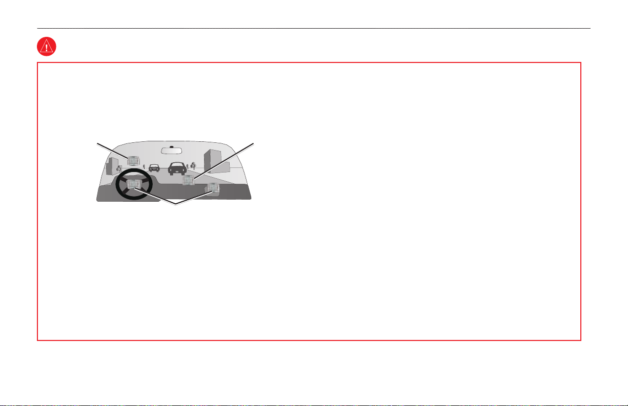
When installing the unit in a vehicle, place the unit securely so it does not
•
obstruct the driver’s view of the road or interfere with vehicle operating
controls, such as the steering wheel, foot pedals, or transmission levers.
Do not place in front of or above any airbag. (See diagram.)
Do not mount
where driver’s
eld of vision is
blocked.
Do not mount in front of an airbag eld of deployment.
When navigating, carefully compare information displayed on the unit to
•
Do not place
unsecured on
the vehicle
dashboard.
all available navigation sources, including information from street signs,
visual sightings, and maps. For safety, always resolve any discrepancies
or questions before continuing navigation and defer to posted road signs.
Always operate the vehicle in a safe manner. Do not become distracted
•
by the unit while driving, and always be fully aware of all driving
conditions. Minimize the amount of time spent viewing the unit’s
screen while driving and use voice prompts when possible. Do not input
destinations, change settings, or access any functions requiring prolonged
use of the unit’s controls while driving. Pull over in a safe and legal
manner before attempting such operations.
The unit is designed to provide route suggestions. It is not designed to
•
replace the need for driver attentiveness regarding road closures or road
conditions, trafc congestion, weather conditions, or other factors that
may affect safety while driving.
Use the electronic chart in the unit only to facilitate, not to replace, the
•
use of authorized government charts. Ofcial government charts and
notices to mariners and pilots (NOTAMs) contain all information needed
to navigate safely.
When navigating in an aircraft, use the GPSMAP 396 only as an aid
•
for VFR navigation. Use terrain and obstacle data only as an aid to
situational awareness.
Use this unit only as a navigational aid. Do not attempt to use the unit
•
for any purpose requiring precise measurement of direction, distance,
location, or topography. This product should not be used to determine
ground proximity for aircraft navigation.
This TFR Overlay Display System (TDOS) is updated Monday -Friday,
•
1200-2000 UTC. COMFIRM DATA ACCURACY THROUGH
ALTERNATE SOURCES AT OTHER TIMES. For interpretation of this
TFR contact your local FSS.
iv GPSMAP 496 Owner’s Manual
Page 7

IntroductIon > WArnIng
Battery Warnings
If these guidelines are not followed, the internal lithium-ion battery may
experience a shortened life span or may present a risk of damage to the
GPS unit, re, chemical burn, electrolyte leak, and/or injury.
Contact your local waste disposal department to properly dispose of the
•
unit/battery.
Do not leave the unit exposed to a heat source or in a high temperature
•
location, such as in the sun in an unattended vehicle on a hot day. To
prevent damage, remove the unit from the vehicle or store it out of direct
sunlight, such as in the glove box.
Do not punture or incinerate.
•
When storing the unit for a limited length of time, store within the
•
following temperature range: -4° to 140°F (-20° to 60°C). When storing
the unit for an extended time, store within the following temperature
range: 32° to 77°F (0° to 25°C).
Do not operate the unit outside of the following temperature range: -4°
•
to 131°F (-20° to 55°C).
Do not recharge the battery out of the unit or disassemble the battery.
•
Keep the used battery away from children. Do not disassemble,
•
puncture, or damage the battery.
Only replace with a Garmin lithium-ion battery pack. Using another
•
battery presents a risk of re or explosion. To purchase a replacement
battery, see your Garmin dealer or the Garmin Web site.
WARNING: This product, its packaging, and its components contain
chemicals known to the State of California to cause cancer, birth defects, or
reproductive harm. This notice is provided in accordance with California’s
Proposition 65. See www.garmin.com/prop65 for more information.
Important Information
MAP DATA INFORMATION: One of the goals of Garmin is to provide
customers with the most complete and accurate cartography that is
available to us at a reasonable cost. We use a combination of governmental
and private data sources, which we identify in product literature and
copyright messages displayed to the consumer. Virtually all data sources
contain some inaccurate or incomplete data. In some countries, complete
and accurate map information is either not available or is prohibitively
expensive.
TFR Data: Temporary Flight Restriction (TFR) data is provided by the
FAA and may not be updated outside of normal business hours. Conrm
data currency though alternate sources and contact your local FSS for
interpretation of TFR data.
The California Electronic Waste Recycling Act of 2003 requires the
recycling of certain electronics. For more information on the applicability
to this product, see www.erecycle.org.
GPSMAP 496 Owner’s Manual v
Page 8

IntroductIon > cAre InforMAtIon
Care Information
Contact Garmin if you have any questions while using your
GPSMAP 396. In the USA contact Garmin Product Support by
phone: (913) 397-8200 or (800) 800-1020, Monday–Friday,
8 AM–5 PM Central Time; or go to www.garmin.com/support.
In Europe, contact Garmin (Europe) Ltd. at +44 (0) 870.8501241
(outside the UK) or 0808 2380000 (within the UK).
Cleaning the Unit
The GPSMAP 496 is constructed of high quality materials and does
not require user maintenance other than cleaning. Clean the unit
using a cloth dampened with a mild detergent solution and then wipe
dry. Avoid chemical cleaners and solvents that may damage plastic
components.
Storing the GPSMAP 496
Do not store the GPSMAP 496 where prolonged exposure to
temperature extremes can occur (such as in the trunk of a car) as
permanent damage may result. User information, such as waypoints
and routes, is retained in the unit’s memory without the need for
external power. It is always a good practice to back up important
user data by manually recording it or downloading it to a PC
(transferring it to MapSource).
Immersing the Unit in Water
The GPSMAP 496 is waterproof to IEC Standard 60529 IPX7. It can
withstand immersion in 1 meter of water for 30 minutes. Prolonged
submersion can cause damage to the unit. After submersion, be
certain to wipe and air dry the unit before reuse or charging.
vi GPSMAP 496 Owner’s Manual
Page 9
gettIng stArted > unIt overvIeW
GettInG Started
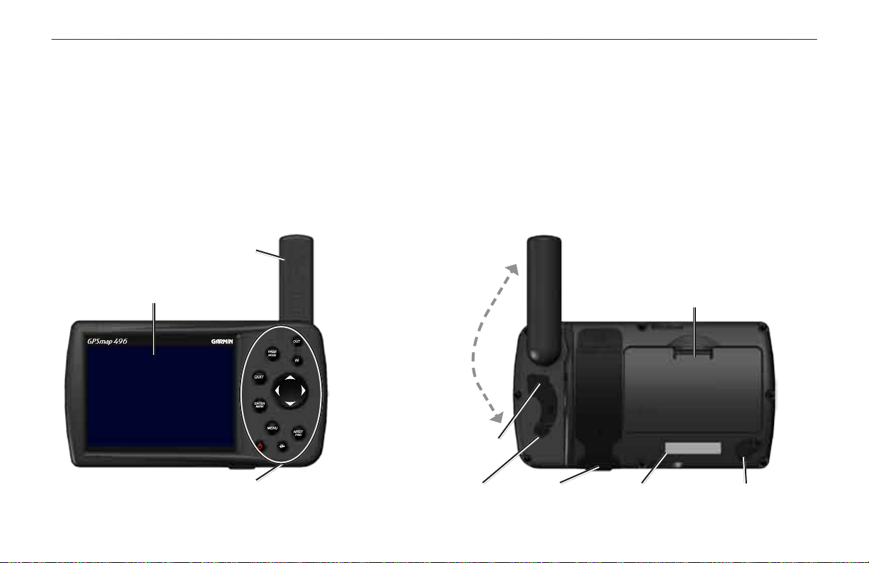
Unit Overview
The GPSMAP 496 is an all-in-one, versatile color aviation, automotive, and marine navigator—perfect for air, land, or water. This portable
GPS navigator features a 256-color TFT screen that is easy to read in bright sun, a built-in City Navigator basemap, Jeppesen aviation
database, and auto routing to provide you with automatically generated turn-by-turn directions.
GPS antenna
256-Color TFT screen
with backlighting
Backlit keypad for easy nighttime operation
GPSMAP 496 Owner’s Manual 1
Detachable GPS
antenna collapses
for storage. Be sure
the antenna is up
(as shown here) to
receive satellite
signals. Refer
to page 138 for
instructions on
removing the
antenna.
External power
connector under
weather cap
USB/ connector under
weather cap
Battery pack. Press tab down to remove battery
pack for replacement, if necessary. See the
“Battery Warnings” section on page v for more
information about the lithium-ion battery pack.
Slot for optional
data card
Serial
number
Audio (Headphones/Line out)
connector under weather cap
Page 10

gettIng stArted > chArgIng the gPsMAP 496
Charging the GPSMAP 496
Before using the unit, you need to charge the battery in the
GPSMAP 496. Plug the unit into a vehicle power connector to
charge. You can use the unit while it is charging.
If you do not want to use the unit, but you would like to charge the
battery, you can put the unit into Charge Mode. Connect the unit to
an external power supply. Press and hold the POWER key. Instead
of completely turning off, the unit now goes into Charge Mode, as
shown below.
To charge the unit’s battery:
1. Lift the rubber weather cap to expose the power connector
on the back of the unit. Refer to the image on page 1 for
connector location.
2. Align the notches, and push the plug into the connector until
fully seated.
3. Plug the vehicle power cable into a vehicle power outlet
(cigarette lighter receptacle) if you have a vehicle power
cable. Use care when routing the power cable; be certain that
it does not interfere with vehicle operation.
The unit begins charging as soon as external power is applied.
NOTE: While in Charge Mode, the unit draws a small amount
Placing the unit in Charge Mode charges the unit more quickly than
when the unit is turned on and reduces draw on the aircraft/vehicle/
boat battery.
Information about Charge Mode
Applying external power to the GPSMAP 496 automatically turns
on the unit for full operation. If the battery is present and needs to be
charged, the external power source charges the battery while the unit
is in use.
After using the unit a lot, you may notice that the lithium-ion battery
in the unit is not holding a charge any more. This is common for
lithium-ion batteries. Contact Garmin or your Garmin Dealer to
order a Battery Pack replacement if you are experiencing charging
issues with your battery.
Charge Mode
of current from the aircraft/vehicle/boat battery. To avoid
discharging the vehicle’s battery, disconnect the external power
cable from the GPSMAP 496 when not in use for several days.
2 GPSMAP 496 Owner’s Manual
Page 11
gettIng stArted > turnIng on the gPsMAP 496
Turning On the GPSMAP 496
3. To turn off the GPSMAP 496, press and hold the
The rst time you turn on your new GPSMAP 496, the receiver
must collect satellite data and establish its present location. To
ensure proper initialization, the GPSMAP 496 is shipped from the
factory in AutoLocate mode, which allows the receiver to “nd
itself” anywhere in the world. Before you turn on the unit to start
Adjusting the Backlight and Volume
The POWER key controls the 10 level backlight and volume of
the optional headphone jack or external speaker with vehicle power
cable.
initialization, be sure that the antenna is rotated up as shown on
page 1, and it has a clear and unobstructed view of the sky to receive
satellite signals.
To adjust the backlight level or volume:
1. Press and quickly release the POWER key.
2. Press the ROCKER up to increase the brightness or down to
To turn the GPSMAP 496 on and off:
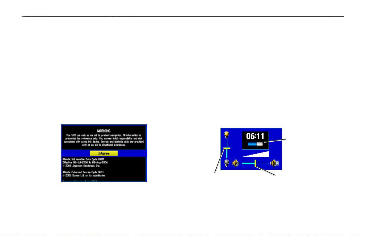
1. Press and hold the red POWER key. When the unit turns on,
a tone sounds and the Warning Page appears.
Warning Page
3. Press ENTER or QUIT to close the Backlight/Volume
POWER key
again.
decrease. Press right to raise the volume or left to lower.
adjustment window. Press MENU to view the options menu.
Battery time remaining
and power source
indicator
Backlight
adjustment slider
Volume
adjustment slider
2. Read and be sure you understand the warning. Press ENTER
to continue.
GPSMAP 496 Owner’s Manual 3
Page 12
gettIng stArted > gettIng sAtellIte sIgnAls
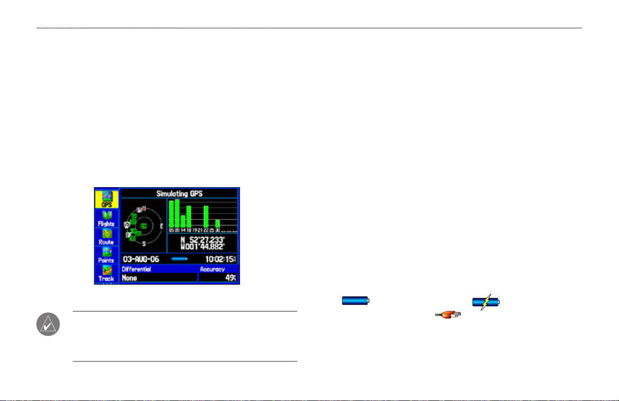
Getting Satellite Signals
After you turn on the GPSMAP 496, the unit automatically begins
searching for satellites. The GPS Page appears while the unit is
gathering satellite signals and acquiring a x. This process should
take only a few minutes. While the GPSMAP 496 is getting satellite
signals, the GPS Page shows the status as “Acquiring Satellites.”
It can take a few minutes to acquire satellites and show your current
location on the map. Be patient as the unit acquires satellite data.
To get signals more quickly, be sure the antenna is raised to the up
position shown in the image on page 1.
Viewing GPS Status With the GPS Tab
The GPS tab provides a visual reference of satellite acquisition,
receiver status, and accuracy. The sky view and signal strength bars
give an indication of what satellites are visible to the receiver and
whether they are being tracked.
As the receiver locks onto satellites, a signal strength bar appears
for each satellite in view, with the appropriate satellite number
underneath each bar. The numbers shown below each bar represent
the particular satellite that is being received. Numbers above 33
indicate EGNOS satellites.
The sky view shows a birds-eye view of the location of each satellite
relative to the receiver’s last known location. The outer circle
represents the horizon (north up), the inner circle represents 45º
above the horizon, and the center point represents a location directly
overhead. You can also set the sky view to a Track Up conguration,
causing the top of the sky view to align along your current track
heading.
GPS Page
A power source indicator shows the unit is operating off battery
power ( ), that the unit is charging ( ), or that an
NOTE: While acquiring satellites, the Map Page can show the
wrong location, such as China. This does not mean your unit
has the wrong data loaded. The GPS receiver needs a few more
minutes to acquire satellites and nd your current location.
external power source is in use ( ).
4 GPSMAP 496 Owner’s Manual
Page 13
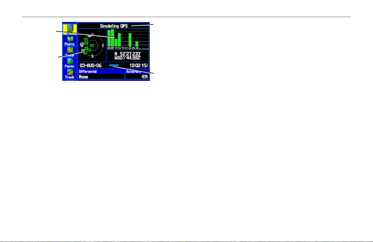
gettIng stArted > gettIng sAtellIte sIgnAls
Signal
strength
bars
Receiver
status eld
Searching the Sky—the receiver is looking for satellites.
•
•
AutoLocate
—the receiver is looking for any satellite whose
almanac has been collected, which can take up to 5 minutes.
Sky view
Power
source
indicator
GPS Page
•
•
The progress of satellite acquisition is shown in three stages:
No
signal strength bar—the receiver is looking for the
•
satellites indicated.
White signal strength bar—the receiver has found the
•
•
satellite and is collecting data.
•
Green signal strength bar
—the receiver has collected the
necessary data from this satellite.
As soon as the GPSMAP 496 has collected the necessary data from
•
the best satellites in view to calculate a x, the status eld indicates
the status of the receiver. The unit then updates the location, date,
•
and time.
Acquiring Satellites
collecting data from satellites visible at its last known or
initialized location, but has not acquired a x.
2D GPS Location
acquired and a two-dimensional location x has been
calculated. “2D Differential” appears when you are receiving
DGPS corrections in 2D mode and a “D” appears on the
strength bar of satellites being corrected.
3D GPS Location
acquired and a three-dimensional x has been calculated.
“3D Differential” appears when you are receiving DGPS
corrections in 3D mode and a “D” appears on the strength bar
of satellites being corrected.
Lost Satellite Reception
enough satellites for a 2D or 3D x.
Receiver Not Usable
to interference or abnormal satellite conditions. Turn the unit
—the receiver is looking for and
—At least three satellites have been
—At least four satellites have been
—the receiver is no longer tracking
—the receiver is unusable, possibly due
off and back on to reset.
Receiver Status
The Receiver Status eld shows one of the following conditions:
GPSMAP 496 Owner’s Manual 5
•
Simulating GPS
•
GPS Off
—the GPS receiver is turned off.
—the receiver is in Simulator Mode.
Page 14
gettIng stArted > gettIng sAtellIte sIgnAls
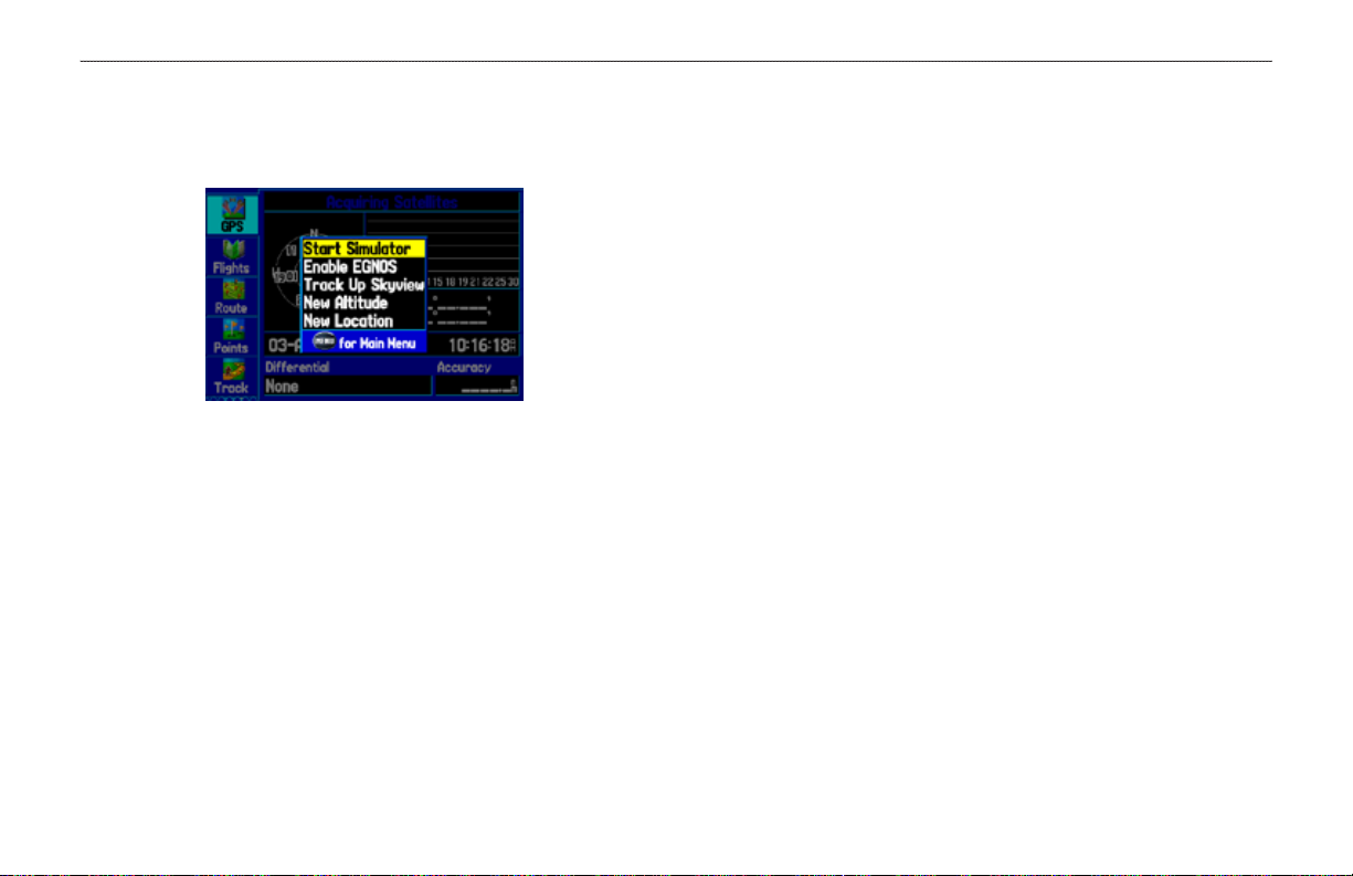
GPS Tab Options
Press MENU two times to open the Main Menu. Use the ROCKER
to highlight GPS. Press MENU to open the options menu:
GPS Tips
While the receiver is gathering information, your location on the
map can show as different from where you actually are located. Be
patient; as soon as the receiver gathers enough satellite information,
your proper location is shown on the map.
Any time you have traveled more than 600 miles with the GPS
receiver turned off, the receiver can take longer than normal to
initialize and nd your location.
The GPS receiver can lose satellite signals due to interference from
such items as buildings, tunnels, and heavy tree cover. Monitoring
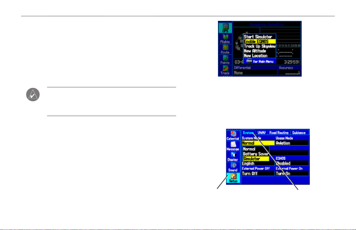
GPS Tab Options Menu
Start/Stop Simulator—starts and stops Simulator Mode, which is
the GPS status is recommended.
To learn about GPS, refer to “Learning about GPS” on page 139.
helpful when learning how to use your unit.
Enable EGNOS
—enables EGNOS capability. Refer to page 139 for
more information about EGNOS.
Track/North Up Skyview
—orients the sky view page on the GPS
tab to north up or track up.
New Altitude
New
Location—allows you to enter a new location automatically
—allows you to manually enter your altitude.
or using the map. When in Aviation Mode, you can enter the airport
identier.
6 GPSMAP 496 Owner’s Manual
Page 15
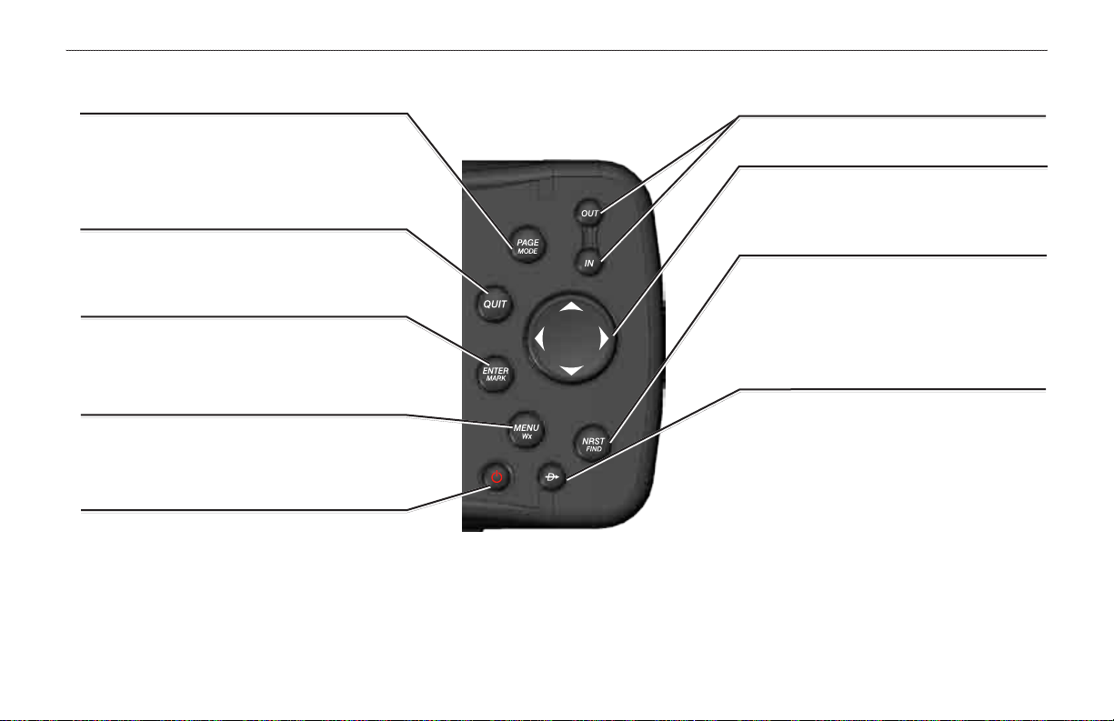
Learning About the Keypad
PAGE/MODE Key
• Press to cycle through the main pages in sequence
and return the screen from a submenu page.
• Press and hold to switch between Aviation, Marine,
and Automotive Modes.
QUIT Key
• Press to cycle through the main pages in reverse
sequence, revert to the previous value in a data
entry eld, or cancel a function.
ENTER/MARK Key
• Press to select a highlighted option, initiate entry,
and then conrm.
• Press and hold to mark a waypoint.
MENU Key
• Press to view the Options Menu for the current
page.
• Press twice to show the Main Menu.
POWER Key
• Press and hold to turn the unit on or off.
• Press and release to adjust the backlighting and
external speaker volume.
gettIng stArted > leArnIng About the KeyPAd
IN/OUT Keys
• Press to zoom in or out on the Map Page.
ROCKER Keypad
• Press up, down, right or left to move through
lists, highlight elds, on-screen buttons and
icons, enter data, or move the map pointer.
NRST/FIND Key
• Shows the nearest airports, navaids, points of
communication, and airspace boundaries in
Aviation Mode.
• Press multiple times in Aviation Mode to show
the Find Menu.
DIRECT TO Key
• Press to start a Go To using airports, navaids,
recently used waypoints, or user-created
waypoints.
• Press and hold to show additional information
for the current destination (such as
communication frequency and runway data).
• While in Automotive Mode, press and hold for
more than one second to show the Next Turn
Page and announce the next turn.
GPSMAP 496 Owner’s Manual 7
Page 16
gettIng stArted > usIng the gPsMAP 496
Using the GPSMAP 496
This section explains how to enter and select information with the
GPSMAP 496. To switch between Aviation, Marine, and Automotive
Modes, press and hold PAGE. Use the ROCKER to select a mode,
and press ENTER.
Understanding Terms
The GPSMAP 496 unit’s advanced keypad system is designed to
allow quick, convenient selection of navigation options and data
entry. As you progress through this owner’s manual, you are directed
to press a specic key or highlight a eld on the screen. When you
are directed to press a key, you should press and quickly release the
key. If the key needs to be held down for a period of time to start a
secondary function, the instructions tell you to do so. When a eld is
selected on the screen, it is highlighted in yellow. The location of the
Field—the location on a page where data or an option can be
entered and shown. Select (highlight) a eld using the ROCKER to
begin entering data or selecting options.
On-Screen Button
press ENTER to select the button.
Scroll Bar—when viewing a list of items too long to show on
the screen, a scroll bar appears along the right side of the list.
The location of the scroll bar indicates which portion of the list is
currently shown. To scroll through a list, press up or down on the
ROCKER
Default—the factory setting saved in the unit’s memory. You can
change the settings as you like, but you can also revert to the factory
(default) settings when you select Restore Defaults.
highlight is controlled by the ROCKER.
The following features are referred to throughout this manual:
Highlight—move the highlighted area on the screen up, down, left,
or right with the ROCKER to select individual elds. Moving the
highlight to a given location allows you to make a selection, begin
data entry, or scroll through a list.
—use the ROCKER to highlight a button and
.
Field
8 GPSMAP 496 Owner’s Manual
On-screen
buttons
Page 17
gettIng stArted > usIng the gPsMAP 496
Selecting Options and Entering Data
To enter data and select options, you must use the ROCKER to
highlight, select, or choose an item in a list or a eld on the screen.
Use the ENTER and ROCKER keys to select options, enter names
and numbers in data elds, and start your selections.
To exit a menu or return to the previous setting:
1. Press QUIT to move backward through your steps.
2. To return to the starting page, press QUIT repeatedly.
To select and start an on-screen button:
1. On a page with on-screen buttons, use the ROCKER to
To select and start an option:
1. Press MENU on any page. An options menu appears with a
list of optional features for that page.
2. Use the ROCKER to move the highlight up, down, right, or left
on the menu to your selection.
Selecting an option from an options menu.
2. Press ENTER.
highlight the on-screen button you want.
On-Screen Button
GPSMAP 496 Owner’s Manual 9
Page 18
gettIng stArted > usIng the gPsMAP 496
To enter data in a data eld:
1. Use the ROCKER to highlight the data eld you want, and
press ENTER to activate the eld.
2. Press up or down on the ROCKER to select characters. Press
right to move to the next character or press left to move back
to the previous character. If there are two lines of data, keep
pressing right to drop to the next line.
3. After entering the data, press ENTER.
GPSMAP 496 Databases
Your GPSMAP 496 comes with built-in City Navigator street and
points of interest mapping, Jeppesen® database, Obstacle database,
Terrain database, and Voice Guidance database. You also should
update your Jeppesen database to use the most current data. Refer to
page 144 for more information.
MapSource Detailed Maps
Optional Garmin data cards and MapSource CD-ROMs enhance the
versatility of your GPSMAP 496. With optional BlueChart g2 data,
you can access marine navaids, wrecks, obstructions, and anchorage
locations.
The included USB Interface Cable or an optional PC Interface Cable
(with a serial connector) is used to transfer MapSource CD-ROM
data to the optional data card.
Entering Data
For compatible MapSource products, refer to the Garmin Web site at
www.garmin.com/cartography.
NOTE: To clear the entire data eld, highlight the left-most
character eld and press left once more on the ROCKER.
Not all elds are programmable. When you are on a page with elds
that are not selectable, the highlight skips over them.
10 GPSMAP 496 Owner’s Manual
Page 19
Simulator Mode
The GPSMAP 496 contains a Simulator Mode. Simulator Mode
is helpful for practicing with the unit indoors or when no satellite
signals are available or if the antenna is not connected. All
waypoints and routes created in Simulator Mode are retained in
memory for future use. The following section describes how to use
Simulator Mode and walks you through some basic navigation using
the simulator.
NOTE: Do not attempt to navigate using Simulator Mode. When
the unit is set to Simulator Mode, the GPS receiver is turned off.
Any Satellite Signal Strength Bars shown are only simulations
and do not represent the strength of actual satellite signals.
Starting Simulator Mode
You can start Simulator Mode from the GPS tab or the Setup tab on
the Main Menu.
To start Simulator Mode using the GPS tab:
1. Press MENU twice to show the Main Menu.
2. Highlight GPS from the vertical menu.
3. Press MENU to open the GPS tab options menu.
4. Highlight Start Simulator, and press ENTER.
To start Simulator Mode using the Setup tab:
1. Press MENU twice to show the Main Menu.
2. Highlight Setup from the vertical menu.
3. Highlight the System sub tab.
4. Select Simulator from the System Mode eld.
Setup tab
gettIng stArted > sIMulAted bAsIc nAvIgAtIon
System tab
GPSMAP 496 Owner’s Manual 11
Page 20

gettIng stArted > sIMulAted bAsIc nAvIgAtIon
Entering a New Location
From the GPS options menu you can enter a New Location and
New Altitude to simulate from.
To enter a New Location using the map:
1. Press MENU twice, and highlight GPS from the vertical menu.
2. Press MENU to open the options menu.
3. Highlight New Location, and press ENTER.
4. Highlight Use Map, and press ENTER.
5. Use the ROCKER to move the panning arrow to the location
on the map you want, and press ENTER.
You can also select a New Location by entering an airport identier
(code). Select Use Identier from the GPS tab options menu. Enter
the airport code using the ROCKER. Refer to page 14 for complete
instructions about entering airport identiers and user waypoints.
To adjust the simulated speed, heading, and altitude
from the Panel, Pointer, or Highway pages:
1. Press up on the ROCKER to increase the speed in
10 knot/kph/mph increments. Press down on the ROCKER to
decrease the speed in the same increments.
2. Press left or right on the ROCKER to change heading.
3. Press the IN and OUT Zoom keys to increase or decrease
altitude (Aviation Mode only).
12 GPSMAP 496 Owner’s Manual
Page 21
bAsIc oPerAtIon In AvIAtIon Mode > AvIAtIon Mode PAge sequence
BaSIc operatIon In avIatIon Mode
Aviation Mode Page Sequence
The GPSMAP 496 offers three usage modes, Aviation Mode (default), Automotive Mode, and Marine Mode. The main pages are linked
together in a series that you can cycle through by pressing PAGE to move forward and QUIT to reverse. Each page also has an options menu
that allows you to customize each page (in all three modes) to your preferences and/or select features that specically relate to that page. To
view the options menu for any page, press MENU.
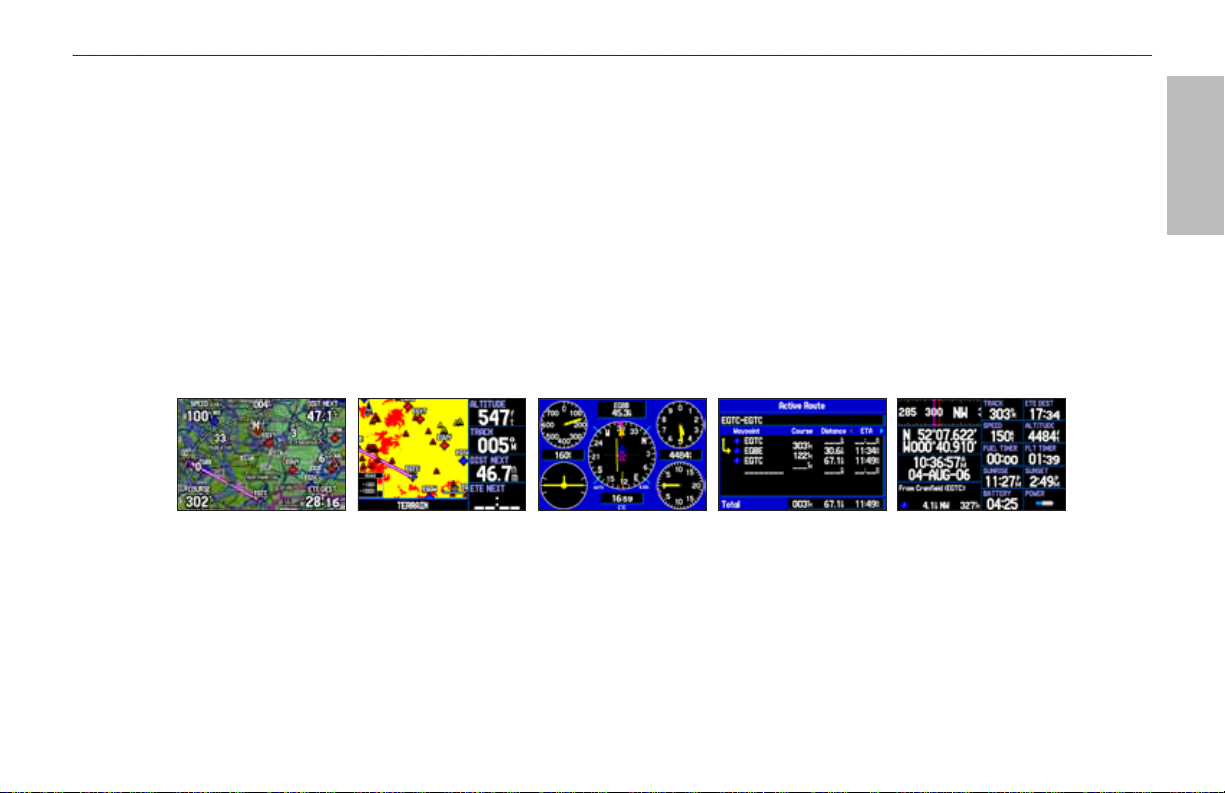
Aviation Mode features ve main pages: Map Page, Terrain Page, Panel Page, Active Route Page, and Position Data Page. An example of
each page in Aviation Mode appears below. Each page has a specic use and is discussed later in this manual. Aviation Mode is the default
mode for the GPSMAP 496. This manual rst addresses each page, such as the Map Page, as shown in Aviation Mode. The manual then
describes the page as shown in Automotive and Marine Mode.
Panel Page Active Route Page Terrain Page Map Page Position Data Page
To switch usage modes:
1. Press and hold PAGE/MODE.
2. Use the ROCKER to select either Aviation, Automotive, or Marine, and press ENTER.
avIatIon
GPSMAP 496 Owner's Manual 13
Page 22
bAsIc oPerAtIon In AvIAtIon Mode > creAtIng A dIrect to
Creating a Direct To
avIatIon
In Aviation Mode, press Direct To to select a destination. When
a Go To or route is currently in use, holding Direct To down
briey shows a detailed information page for the current destination.
In Marine or Automotive Mode, pressing Direct To shows the
Navigate menu, which allows you to start navigation or edit a route.
Also, in Marine Mode, pressing Direct To twice creates a MOB
waypoint and starts navigating to that point.
Press MENU on any tab of the Go To Page to open an options menu
for that tab. Based on the tab you selected, you can Show Details,
Select Approach, Select Route, Find Land Points, and Remove
Point.
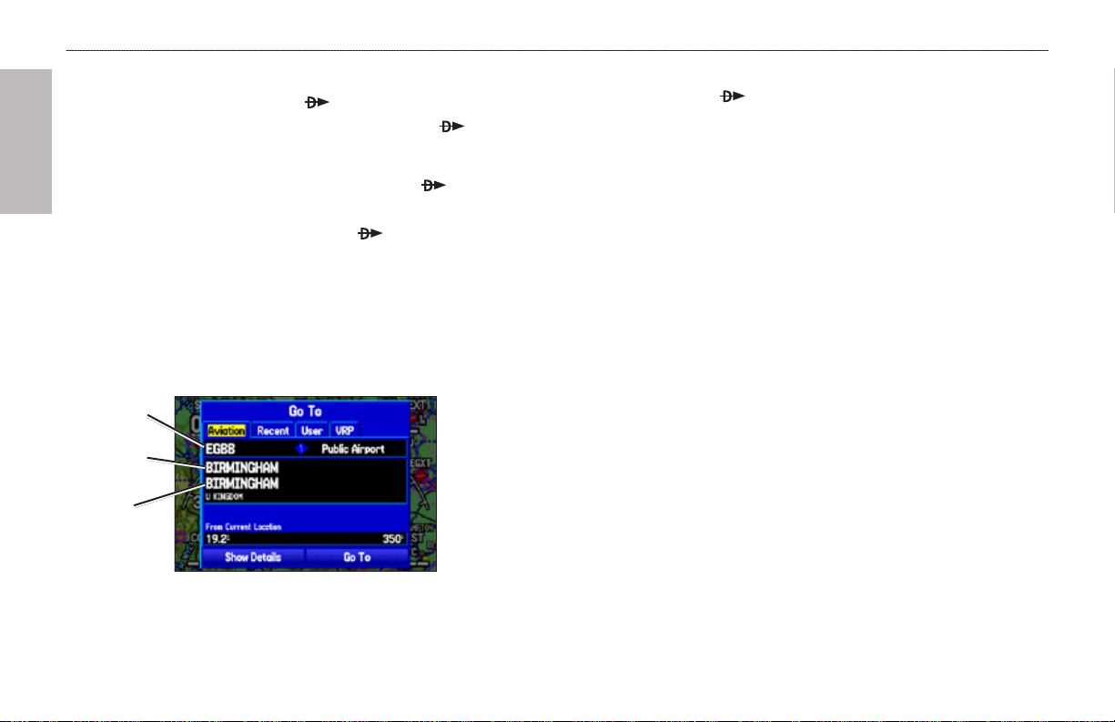
Airport
identier
Facility
name
City
Go To Page: Aviation Tab
To go to an airport or navaid:
1. Press Direct To to show the Go To Page. Use the
ROCKER to show the Aviation tab.
2. Press up or down on the ROCKER to select the identier,
facility name, or city eld, and press ENTER.
3. Use the ROCKER to enter the search word. Press up and
down to change the highlighted character and right to move to
the next character eld. As you scroll through the characters
the GPSMAP 496 shows database entries with the same
characters you have entered to that point. If more than one
entry exists in the database for the characters you have
entered, a window appears. Use ENTER and the ROCKER to
select the point.
4. Press ENTER when the point is shown.
5. With the on-screen Go To button highlighted, press ENTER.
The GPSMAP 496 creates a course from your present
location to the selected destination.
14 GPSMAP 496 Owner's Manual
Page 23
bAsIc oPerAtIon In AvIAtIon Mode > creAtIng A dIrect to
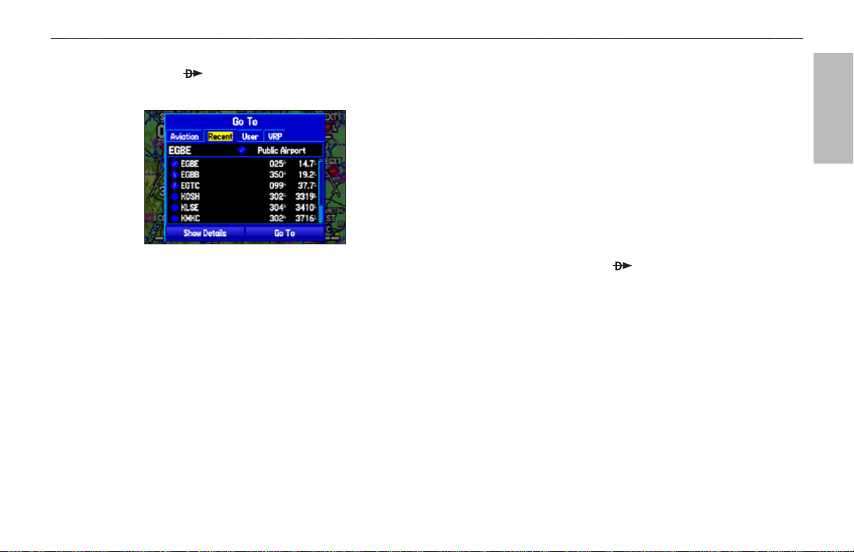
To go to a recently-used or user-created waypoint:
1. Press Direct To to show the Go To Page. Use the
ROCKER to select the Recent or User tab.
Go To Page: Recent Tab
2. Use the ROCKER to highlight the point from the list, and
press ENTER.
From the User tab, you can also select the top waypoint
name line and then spell out the waypoint name using the
ENTER and the ROCKER keys.
3. Highlight the on-screen Go To button, and press ENTER. A
course is plotted from your present location to the selected
destination.
Viewing Details for the Destination
The Show Details option shows detailed information for your
destination waypoint or the next waypoint in a route. This feature
is handy for retrieving airport information, such as communication
frequencies and runway information. You can view details by using the
options menu or by selecting the Show Details button on the Go To
Page, and pressing ENTER.
To view the details for the selected destination:
1. Press MENU to open the options menu. Use the ROCKER to
highlight Show Details, and press ENTER.
OR
Press and hold Direct To .
OR
Use the ROCKER to highlight Show Details, and press
ENTER. A new screen appears showing sub tabs along the
top of the screen.
2. Use the ROCKER to select the tab to view the information.
avIatIon
GPSMAP 496 Owner's Manual 15
Page 24
bAsIc oPerAtIon In AvIAtIon Mode > creAtIng A dIrect to
avIatIon
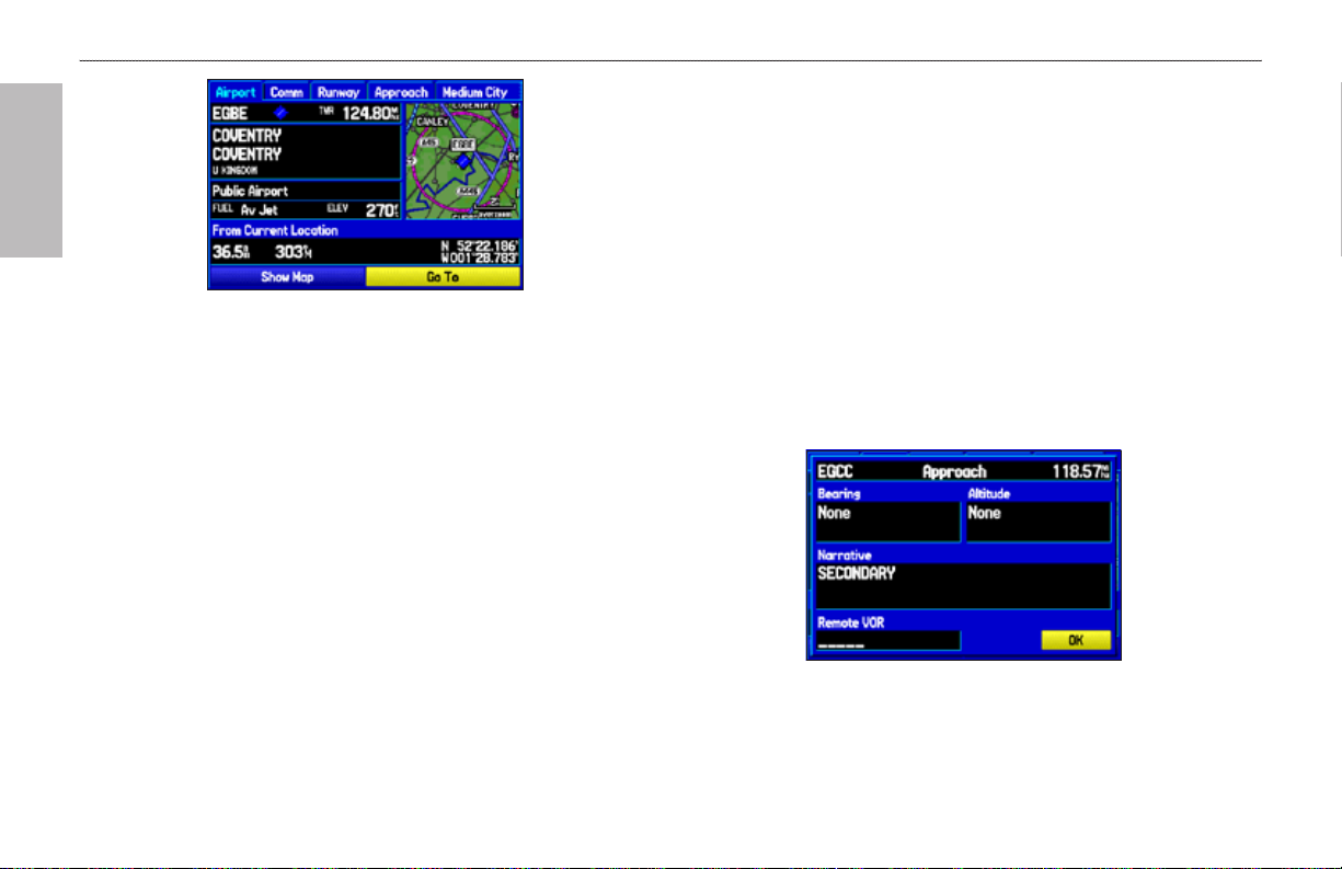
Airport Tab of Details Page
3. Highlight Show Map, and press ENTER to view the item on
the map. Press QUIT when done. Highlight OK, and press
ENTER to return to the Go To Page.
When viewing information for the Runway or Approach tabs, use
the ROCKER to highlight the runway designation or approach
name, and press ENTER. Then press up or down on the ROCKER
to scroll through available runways and approaches. Press ENTER
to select the runway or approach for which you would like to view
additional information.
Viewing Frequency Restrictions
The Comm tab on the Airport Details Page provides a list of
communication frequencies for that airport. Some frequencies are
noted with an asterisk (*), which indicates that the frequency has
usage restrictions. You can show the usage restriction information on
your GPSMAP 496.
To view usage restrictions for a communication
frequency:
1. With the Comm tab selected, use the ROCKER to highlight
any frequency with usage restrictions (noted with an asterisk),
and press ENTER. A Usage Restrictions Page appears
describing the restrictions for the selected frequency.
Usage Restrictions Page
2. To return to the Comm Information Page, press ENTER.
16 GPSMAP 496 Owner's Manual
Page 25
bAsIc oPerAtIon In AvIAtIon Mode > fIndIng A neArby PoInt
Finding a Nearby Point
In Aviation Mode, press NRST/FIND to open the Nearest Pages.
These pages provide detailed information on the nearest airports,
airport weather sources, navaids, cities, and user waypoints.
In Marine and Automotive Modes, press NRST/FIND to open the
Find Menu. You can easily search waypoints, cities, exits, and tide
stations using the Find Menu.
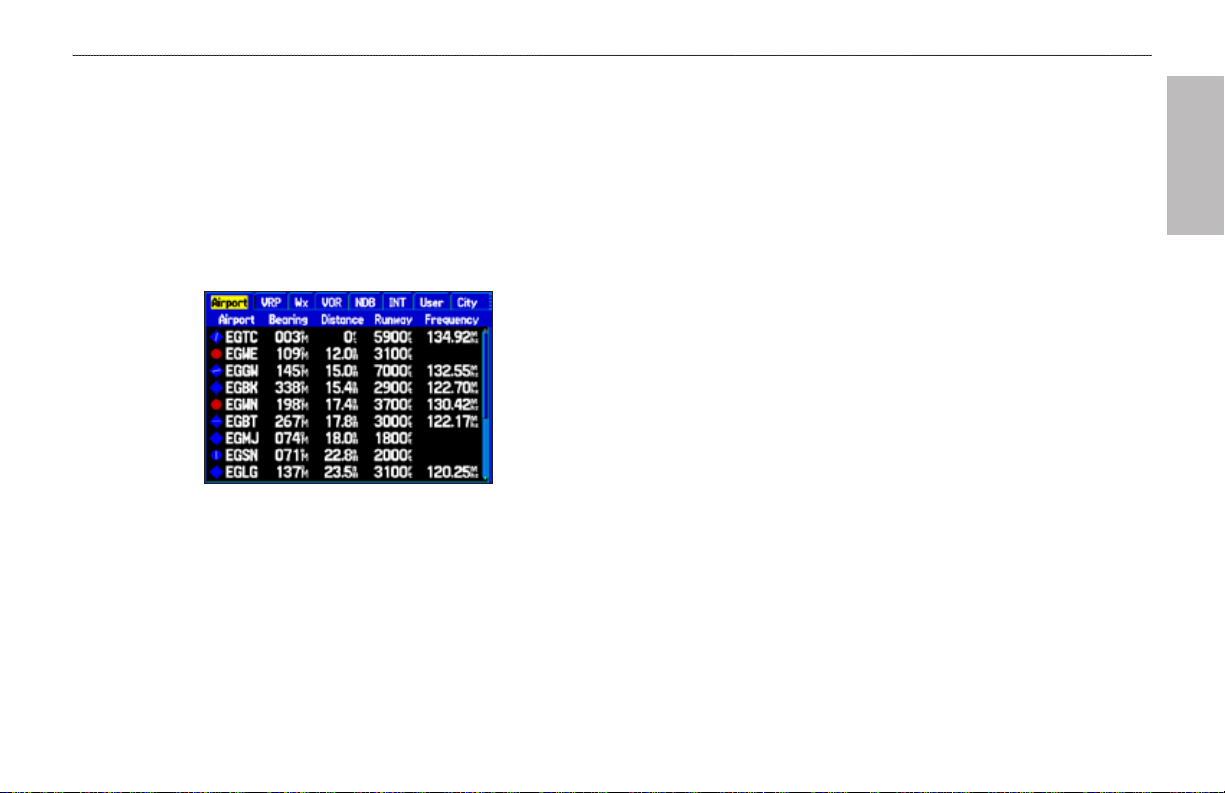
Nearest Page: Airport Tab
While in Aviation Mode
Press MENU when the Nearest Page is open to show the Nearest
Page options menu. You can Show Arrows (or Show Bearing) and
Set Airport Criteria.
Aviation Nearest Categories
In Aviation Mode, the Nearest Pages contain the following
information:
Airport
longest runway, and common trafc advisory (CTAF) or tower
frequency.
VRP (Visual Reporting Point)
and distance.
VOR (VHF Omnidirectional Radio Beacons)
identier, facility type (symbol), bearing, distance, and frequency.
NDB (Non Directional Beacons)
type (symbol), bearing, distance, and frequency.
INT (Intersection)
User (Waypoints)—nearest 15; name, bearing, and distance.
City—nearest 15; name, bearing, and distance.
ARTCC (Air Route Trafc Control Center)—nearest 5; bearing,
distance, and frequency.
FSS (Flight Service Station)—nearest 5; bearing, distance,
frequency, and VOR (for duplex operations).
—nearest 15; identier, bearing, distance, length of the
avIatIon
—nearest 15; identier, bearing,
—nearest 15;
—nearest 15; identier, facility
—nearest 15; identier, bearing, and distance.
Airspace
GPSMAP 496 Owner's Manual 17
—up to 15 (based on number of alerts provided); name,
Page 26
bAsIc oPerAtIon In AvIAtIon Mode > fIndIng A neArby PoInt
time to entry (when applicable), and status.
avIatIon
Selecting a Nearby Point as Your Destination
In an emergency, you can press a few keys to have the GPSMAP 496
guide you to the closest point to land.
To select a nearby point as your destination:
1. Press NRST.
2. Use the ROCKER to select a sub tab along the top of the
page.
3. Highlight the point using the ROCKER.
4. Press Direct To . The Go To Page opens for the selected
point.
OR
You can press ENTER to show the Information Page (Details
Page).
5. Press ENTER when Go To is highlighted.
To select the nearest airport as your destination:
1. Press NRST twice to show the Airport tab and highlight the
nearest airport.
2. Press ENTER to view airport information.
3. Verify the Go To button is highlighted, and press ENTER.
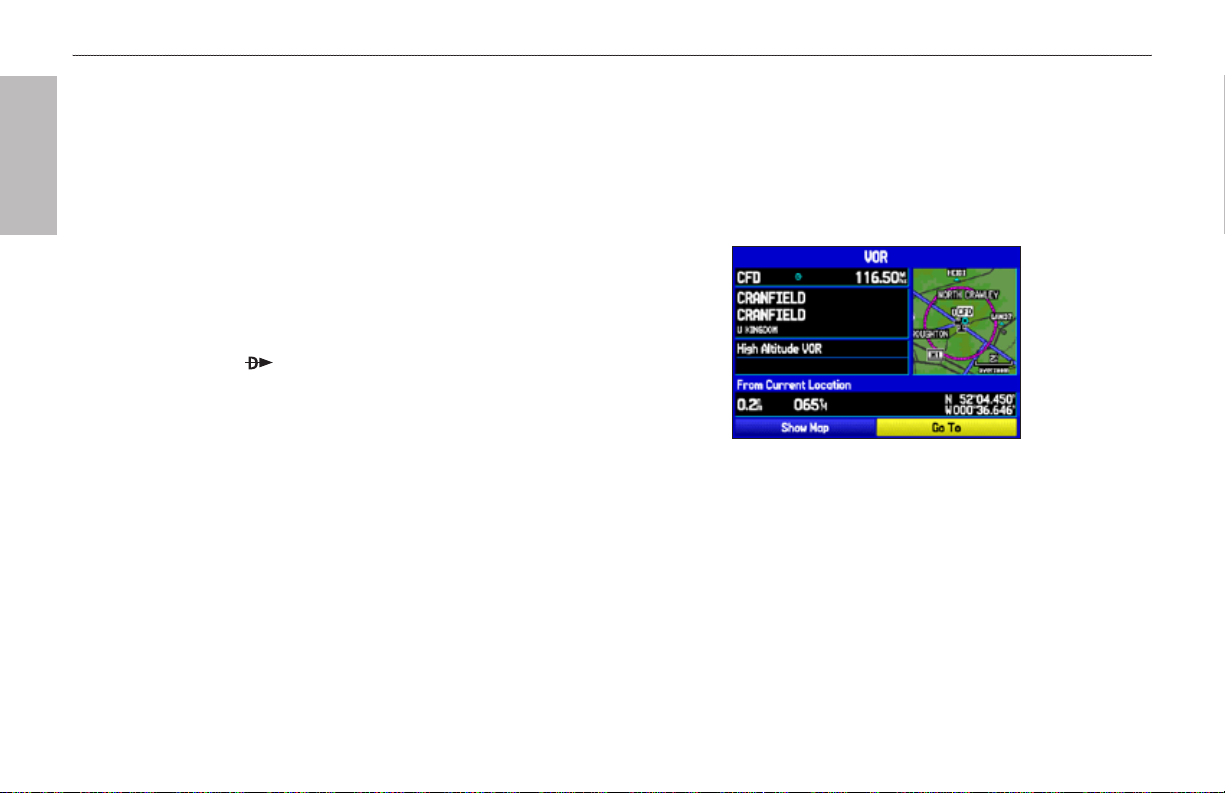
Viewing Details for a Nearby Point
To view details for a nearby point:
1. Press NEAREST to show the nearest pages. Select the sub
tab.
2. Use the ROCKER to highlight the item on the list and press
ENTER. The corresponding information page appears.
Information Page for a VOR
On airport information pages, use the ROCKER to select the
sub tabs across the top of the information pages and show
the airport data.
3. Press QUIT to return to the Nearest Pages. You can also
highlight any one of the on-screen buttons to perform that
action, such as Show Map or Go To.
18 GPSMAP 496 Owner's Manual
Page 27
bAsIc oPerAtIon In AvIAtIon Mode > fIndIng A neArby PoInt
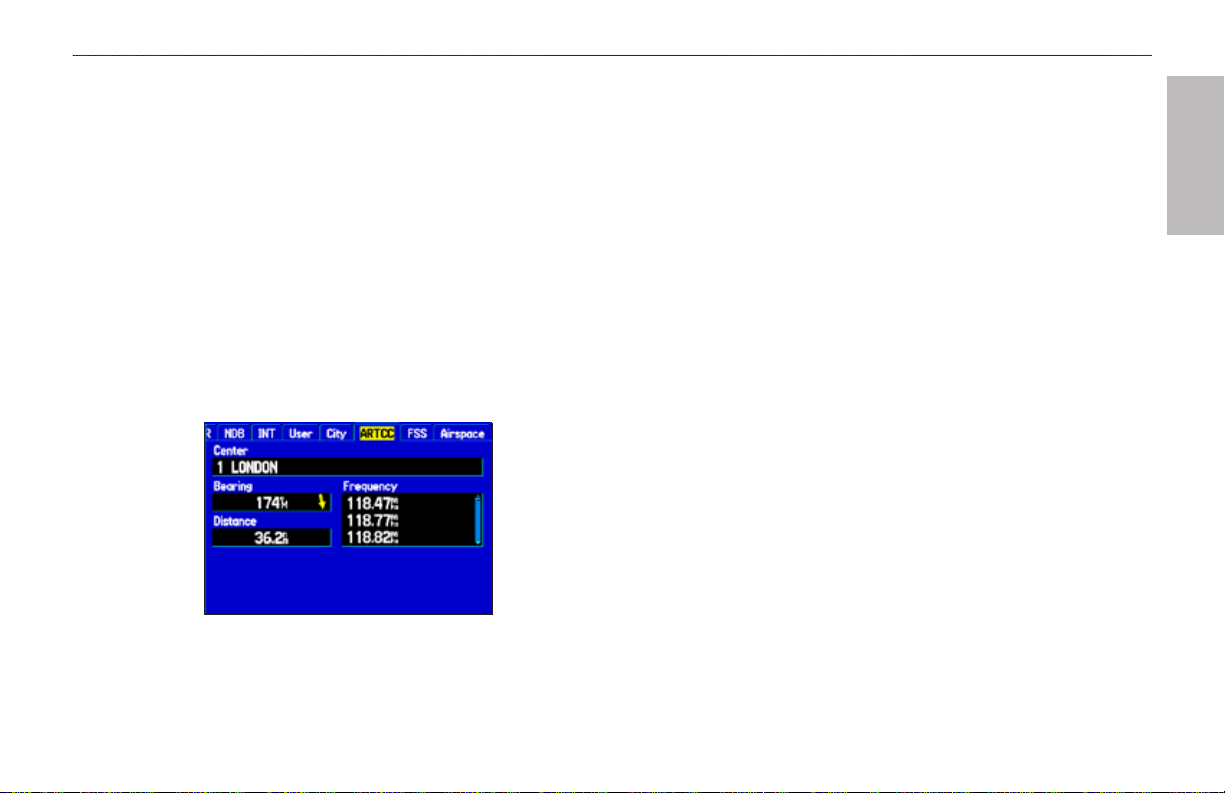
Viewing Communication Frequencies
The Nearest Pages list up to ve nearest ight service stations
(FSS) and air route trafc control center (ARTCC) points of
communication. The closest communication point is shown rst,
with additional points available when selected. For duplex operation,
the corresponding VOR is listed (by identier) and the transmit and
receive frequencies are denoted by a TX and RX respectively.
To view additional communication frequencies:
1. Press NRST to open the Nearest Pages.
2. Use the ROCKER to select the ARTCC or FSS sub tab.
3. Press the ROCKER down to highlight Center or Station
(based which tab you are on), and press ENTER.
ARTCC Tab
Viewing Airspace Alert Information
When an airspace alert appears, press NRST to automatically show
nearby airspace information in the Airspace tab. This information
includes name, time to entry (if applicable), and status. Normally,
only one or two airspace alerts occur at a time, but with sectorized
controlled airspace, such as many TMA areas, there are more. Status
information can appear as follows:
Ahead
the next 10 minutes or less.
Near
projected to enter it.
Near & Ahead
and your current course takes you inside the airspace.
Inside Airspace
4. Select the numbered item that you want from the list, and
press ENTER to show the communication information. The
lowest numbers on the list are the closest communication
points.
avIatIon
—your projected course takes you inside an airspace within
—you are within two nautical miles of an airspace but not
—you are within two nautical miles of an airspace
—you are within the boundaries of the airspace.
GPSMAP 496 Owner's Manual 19
Page 28
bAsIc oPerAtIon In AvIAtIon Mode > fIndIng A neArby PoInt
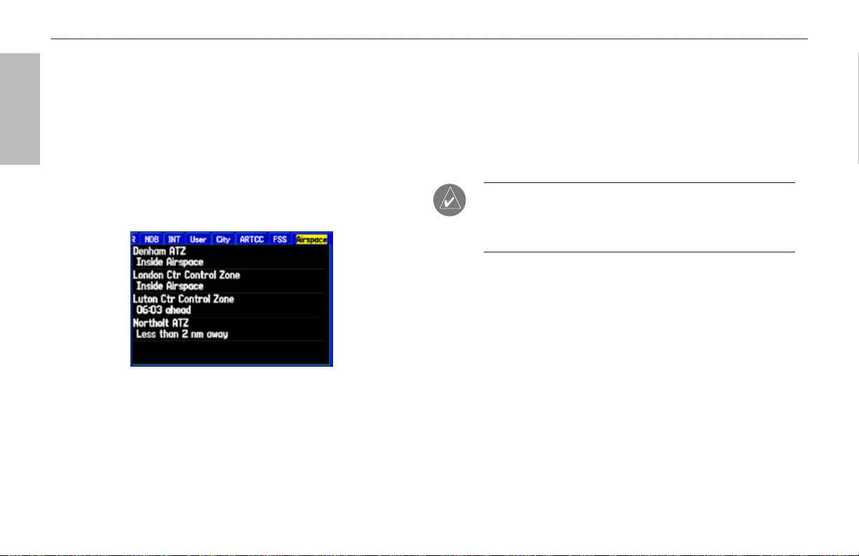
Viewing Additional Airspace Information
avIatIon
From the Nearest Pages, you can show additional airspace
information, such as oor and ceiling limits or communication
frequencies.
To view additional airspace information:
1. When an airspace alert appears, press NRST to show the
Nearest Pages and the airspace information. If you are
already viewing the Nearest Pages, use the ROCKER to
select the Airspace tab.
Nearest Pages: Airspace Tab
2. Use the ROCKER to select the airspace alert entry on the
page, and press ENTER. An information page opens to show
the controlling agency, status, and oor/ceiling limits.
3. To show a communication frequency for the airspace, select
the Frequencies button, and press ENTER.
To return to the Nearest Pages, select the OK button, and
press ENTER.
NOTE: When an airspace alert appears, press NRST to
automatically show nearest airspace information. Press NRST
a second time to quickly show the nearest airports list. Press
NRST a third time to show the Find Menu.
20 GPSMAP 496 Owner's Manual
Page 29
bAsIc oPerAtIon In AvIAtIon Mode > fIndIng A neArby PoInt
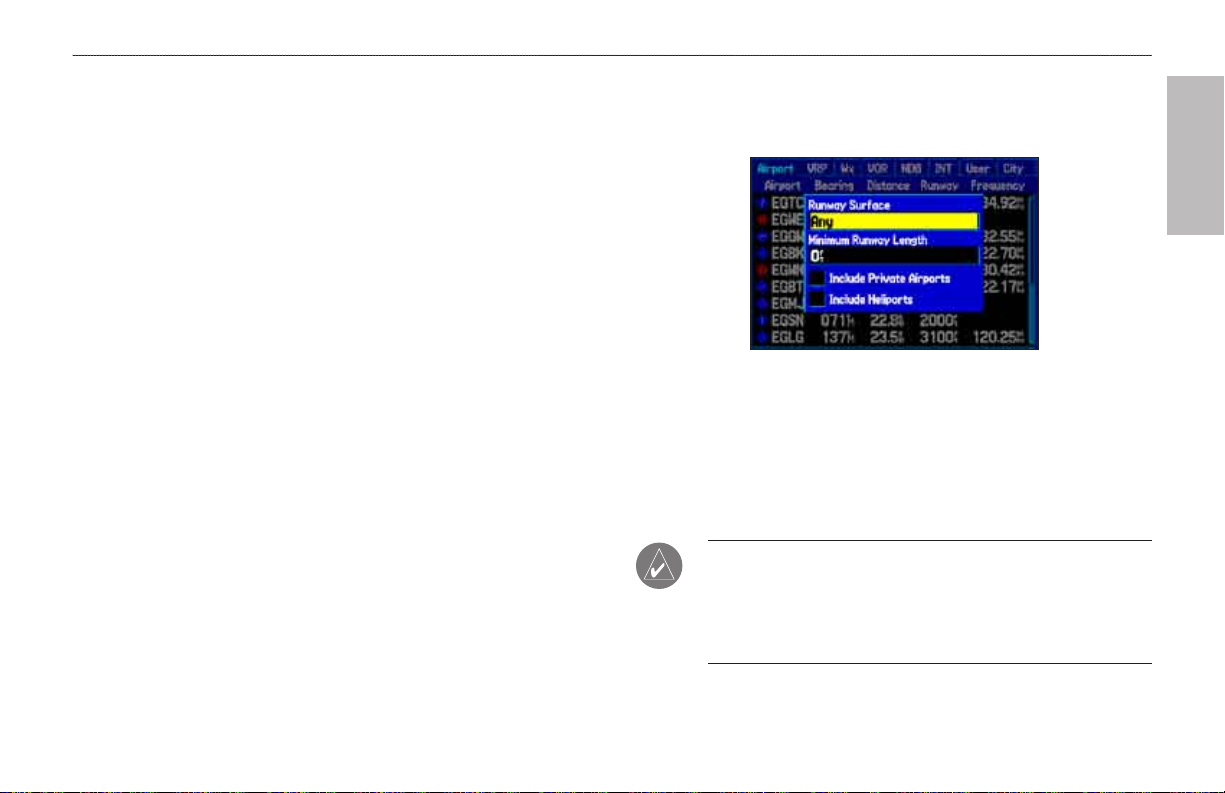
Setting Airport Criteria
3. Select Set Airport Criteria, and then press ENTER. A window
From the Nearest Airport tab, an options window allows you to
lter out airports that do not meet a dened criteria. This allows
you to only show airports with a surface type and sufcient runway
length you want. You can also select the Include Private Airports
and Include Heliports check boxes to include private airports and
heliports in the Nearest Airport tab.
Runway Surface
—allows you to set criteria for the type of surface
on the runway:
Any
—shows any runway, regardless of surface type, including
water landing facilities.
Hard Only
—shows only runways with a concrete, asphalt, or
4. With the runway surface eld highlighted, press ENTER.
similar sealed surface.
Hard or Soft—shows all runways except water landing facilities.
Water Only
Minimum Runway Length
—shows only water landing facilities.
—allows you to enter a specic length
5. Highlight the minimum runway length eld, and press ENTER.
6. Use the ROCKER to enter the minimum acceptable runway
for the shortest runway allowed.
To enter airport criteria:
1. Press NRST, and open the Airport tab.
2. Press MENU to show the options menu.
appears with the current settings for runway surface and
minimum runway length.
avIatIon
Airport Criteria Page
Select the surface type, and press ENTER.
length. Press ENTER.
NOTE: Use caution when changing the nearest airport criteria.
In an emergency, a short runway is still typically preferable to an
off-eld landing. If you set the runway length too low or exclude
many runway surfaces, you may not be alerted to a nearby
airport that otherwise would be listed.
GPSMAP 496 Owner's Manual 21
Page 30
bAsIc oPerAtIon In AvIAtIon Mode > selectIng An APProAch
Selecting an Approach
avIatIon
CAUTION: The approaches provided in the Jeppesen database
are for monitoring purposes only. The GPSMAP 496 is not an
IFR-approved instrument and should not be used as a primary
source of navigation guidance in instrument conditions.
When you select an approach, it replaces the destination airport with
the sequence of waypoints for the selected approach. Keep in mind
that the airport must have a published approach (GPS, RNAV, VOR,
NDB, localizer, or ILS) and only the nal course segment (usually
from nal approach x to missed approach point) of the published
approach is available in the GPSMAP 496.
NOTE: When using a route, the selected approach for the
destination airport overrides your current route. The original
route is saved in the Route tab.
You can select an approach several ways:
Press Direct To and press MENU on the Go To Page, as
•
described in the steps to the right.
From the Active Go To (or Active Route) Page, press MENU.
•
From the Airport Details Page, select the Approach tab.
•
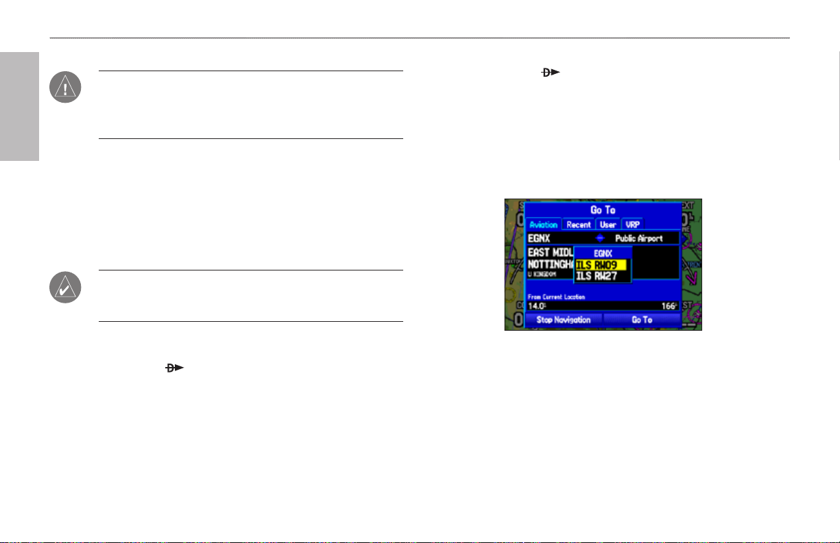
To select an approach for the destination airport:
1. Press Direct To to show the Go To Page. Select the
destination you want to travel to.
2. Press MENU to open the options menu. Highlight Select
Approach, and press ENTER.
3. Use the ROCKER to select the approach from the window,
and press ENTER. A Vectors? window appears. See the
following page for more information on vectors.
Selecting an Approach
4. Use the ROCKER to select Yes or No, and press ENTER.
The GPSMAP 496 removes the destination airport from the
Go To and replaces it with the approach waypoints.
22 GPSMAP 496 Owner's Manual
Page 31

bAsIc oPerAtIon In AvIAtIon Mode > selectIng An APProAch
Understanding Vectors
The Vectors? option, which appears after you select an approach,
determines how you navigate to the nal approach waypoint.
If you select Yes, the GPSMAP 496 creates an extension of the nal
course, beyond the nal approach waypoint in the database (nal
If No is selected for the Vectors? option, the GPSMAP 496 creates
a straight-line course directly to the rst waypoint in the approach
(from wherever you are when you initiate the approach). This works
much like any other route with course guidance from point to point
and a turn usually required as you cross each waypoint.
approach x [FAF]). On the Active Route Page, a Vector to Final
symbol appears beside the rst approach waypoint.
If air trafc control clears your approach to an airport, loading the
approach cancels your Direct To and initiates a route to the FAF.
Load the approach only when cleared by air trafc control.
You can cancel an approach and/or vectors several ways:
Active Approach Page
Using vectors in the approach
The GPSMAP 496 provides no guidance to the inbound course.
The course deviation needle on the graphic HSI remains off-center
until you are established on this nal approach course. The HSI
automatically slews (rotates to show the direction) to the inbound
course. The Map Page shows an extension of the nal approach
course using a bold magenta line.
CAUTION:
Flight Rules) approach. Follow the approach plate or air trafc
control instructions to complete the approach without a steep turn.
Press Direct To , and press MENU on the Go To Page.
•
From the Active Go To (or Active Route) Page, press MENU.
•
Steep Turns are not allowed on an IFR (Instrument
To cancel the vectors and/or approach:
1. Press Direct To to show the Go To Page.
OR
Open the Active Route Page. Press MENU to open the
options menu.
2. Highlight Cancel Approach, and press ENTER to cancel
the entire approach. If you enabled Vectors, highlight Cancel
Vectors, and press ENTER to navigate directly to the FAF.
avIatIon
GPSMAP 496 Owner's Manual 23
Page 32

bAsIc oPerAtIon In AvIAtIon Mode > fIndIng PoInts on lAnd
Finding Points on Land
avIatIon
To take full advantage of the trip-planning capabilities of the
GPSMAP 496, you can nd points on the land and then create a
turn-by-turn route (auto-route) to that point. For example, you can
nd a restaurant to eat dinner at when you land.
To Find Land Points:
1. Press Direct To to show the Go To Page.
2. Press MENU to open the options menu.
Go To Page Options Menu
3. Highlight Find Land Points, and press ENTER. The Find
Menu opens.
Find Menu
4. Press MENU to select the search method. For example, if you
want to nd a land point near your destination, select Near
Destination, and press ENTER.
5. Highlight the nd menu icon for the category, and press
ENTER.
6. Enter the necessary information, such as the restaurant name
and press ENTER. Refer to page 53 for complete information.
7. Select Save to save the location as a waypoint to use later
when creating a route. Select Show Map to show the location
on the map, or select OK to return to the search results list.
24 GPSMAP 496 Owner's Manual
Page 33

bAsIc oPerAtIon In AvIAtIon Mode > MArKIng A WAyPoInt
Marking a Waypoint
Waypoints are locations or landmarks you record and store in your
GPSMAP 496. Press the ENTER/MARK to capture your present
To mark a selected location as a waypoint:
1. Press PAGE to open the Map Page.
2. Use the ROCKER to move the arrow to the location you want
location to create a new waypoint. You must have a valid 2D or 3D
satellite x to mark your location. Press MENU twice and open the
3. Quickly press and release ENTER/MARK to open the
GPS tab to view your satellite receiver status.
For more information about editing waypoints, see the “Editing and
Managing Waypoints” section beginning on page 73.
To mark your present location:
1. Press and hold ENTER/MARK until the Mark Waypoint Page
appears.
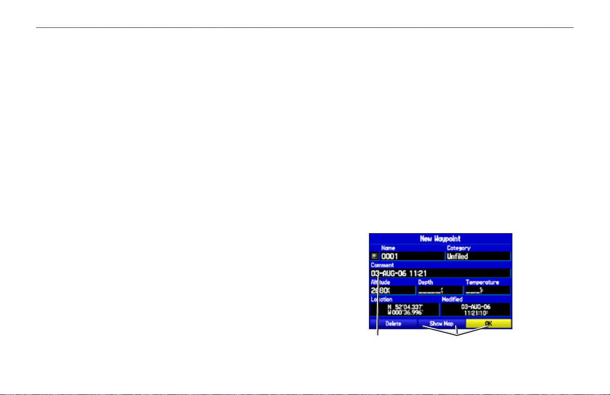
2. To accept the waypoint with the default name (“Waypoint”),
use the ROCKER to highlight OK, and press ENTER.
4. To save the waypoint, use the ROCKER to highlight Save,
5. To accept the waypoint with the default name, highlight OK,
to save as a waypoint.
Information Page for the map item.
Saving the Selected Item as a Waypoint
and press ENTER.
and press ENTER.
avIatIon
GPSMAP 496 Owner's Manual 25
Page 34

bAsIc oPerAtIon In AvIAtIon Mode > creAtIng A flIght PlAn (route)
Creating a Flight Plan (Route)
avIatIon
You can create a Flight Plan (or route) using the Route Page in the
Main Menu. The Route is then saved for future use. You can also
create a route using the Active Route Page for immediate use. For
more information, refer to “Creating Routes” beginning on page 56
and “Editing and Managing Routes” beginning on page 69.
NOTE: After you perform an update to your Jeppesen Database,
verify that all of your ight plans in your unit are still current.
If there is an obsolete Jeppesen aviation point in a saved route,
the route is locked and unusable. You need to create a new route
with current Jeppesen Database points.
To create a route:
1. Press MENU twice to open the Main Menu.
2. Use the ROCKER to highlight Routes, and press ENTER.
3. Press MENU to show the options menu. Use the ROCKER to
highlight New Route, and press ENTER, or highlight the rst
blank line, and press ENTER.
4. Press MENU to show the options menu. Use the ROCKER to
highlight Add Waypoint, and press ENTER.
OR
Highlight the rst blank line, and press ENTER.
5. The Aviation Find Page (Go To Page) opens allowing you to
select an aviation point. Enter the ID, Facility name, or city.
6. Highlight the point in the list. Highlight
The selected point is added to the route.
Highlight a
blank line
and press
ENTER to
continue adding
waypoints.
7. Continue steps 4 through 6 until all points are added to the
route. The route is automatically saved to the unit’s memory.
OK, and press ENTER.
To navigate a saved route:
1. Press MENU twice to open the Main Menu.
2. Use the ROCKER to highlight Routes, and press ENTER.
3. Highlight the route you want to take from the list, and press
MENU.
4. Highlight Activate Route, and press ENTER.
You can also create a ight plan to use at a later time. For more
information, refer to “Creating Routes” beginning on page 56 and
“Editing and Managing Routes” beginning on page 69.
26 GPSMAP 496 Owner's Manual
Page 35

bAsIc oPerAtIon In AvIAtIon Mode > folloWIng your flIght PlAn
Following your Flight Plan
When you have created and started your ight plan (or route), the
GPSMAP 496 guides you to the destination using a variety of tools.
NOTE: After you perform an update to your Jeppesen Database,
verify that all of your ight plans (routes) in your unit are still
current. If there is an obsolete Jeppesen aviation point in a saved
route, the route is locked and unusable. You need to create a new
route with current Jeppesen Database points.
Track Your Progress on the Map Page
On the Map Page, your current location is shown as an airplane (when
in Aviation Mode). You can see how the airplane moves across the
map; this is a graphic view of your ight. Your route is marked with a
magenta line. The airplane should be on top of the magenta line as you
move. When you are on the magenta line, you are directly on course.
Terrain and Obstacle Changes
Press PAGE to open the Terrain Page, and watch the changes in the
terrain and the obstacles you are ying over with the Terrain Page.
Terrain and obstacles that are less than 100 feet from your aircraft are
shown in red. For complete information, see page 36.
View the HSI on the Panel Page
You can use the Panel Page to view the HSI, your bearing to the course,
and other information such as speed, altitude, and ETA.
Use the compass in the center of the page to determine if you are on the
proper course. Also, you can help keep the aircraft within the VNAV
prole when viewing the VNAV indicator.
For complete information about the Panel Page, see the section
“Panel Page,” beginning on page 39.
Alerts
NOTE: In Aviation (and Marine) Mode, the Go To line and
navigation guidance are xed. The From point is the location
where the Go To was initiated. In Automotive Mode, the Go To
line on the map is constantly updated to your present location.
For complete information about the Map Page and the features of
the Map Page, see “Map Page,” beginning on page 28.
As you travel, a variety of alerts appear on your current page, such as
Airspace, Terrain, Obstacle, and Descent Rate Alerts. When an Airspace
Alert pops up, press NRST to view the Airspace Information.
When a Terrain or Obstacle alert pops up, press PAGE or NRST
to open the Terrain Page. From here you can view any terrain and
obstacles that might become a problem to you. Possible points-ofimpact are shown as Xs. Adjust your altitude to avoid the obstacles and
terrain.
avIatIon
GPSMAP 496 Owner's Manual 27
Page 36

AvIAtIon Mode PAges > MAP PAge
avIatIon
avIatIon Mode paGeS
This section discusses the major pages, such as the Map and Terrain
Pages, as well as some additional aviation features, such as E6B.
Map Page
The GPSMAP 496 features a real-time moving map that can do
much more than just plot your course. The Map Page shows map
information (digital cartography) that includes airspace boundaries,
airports, navaids, lakes, rivers, coastlines, cities, and highways.
Dedicated zoom keys (IN and OUT) are provided for range
adjustments.
Two basic map operating modes, location mode and pan mode,
determine what cartography is shown on the Map Page. Location
mode pans the map to keep your present location in the screen area.
The location marker (icon) that shows your travel on the Map Page
is an aircraft symbol in Aviation Mode and a triangle symbol
in Marine and Automotive modes. The GPSMAP 496 always
turns on in location mode, with the last known location centered on
the map. When you press the ROCKER, the GPSMAP 496 enters
pan mode, which moves the map to keep the white arrow (map
pointer) within the screen area.
In Aviation Mode, by default, four user-selectable data elds appear
in the corners of the screen that can be congured to show any one
of the several data options. You can also change the layout of the
map and data elds. See page 33 for information.
Compass arc
Data eld
Airports
Current
location
Map Page (Aviation Mode)
Map zoom
range
A navigation arc (Horizontal Situation Indicator, or HSI) appears
by default on the Map Page. The arc works like the compass on the
Panel Page, indicating the course and your deviation left or right of
this course. If the route line and magenta arrow are heading straight
up, you are heading directly to your destination.
NOTE: The navigation arc only shows up in Aviation Mode
when the Map Page is set to Track Up. See page 33.
28 GPSMAP 496 Owner's Manual
Page 37

AvIAtIon Mode PAges > MAP PAge
Map Orientation
Map coverage conforms to the following conditions:
There are three map orientation options: North Up orients the map
like a paper map, Track Up orients the map in the direction of travel,
and Course Up orients the map in the direction of the destination.
When using Track Up or Course Up, the North arrow indicates the
orientation. To change the map orientation, press PAGE to open the
Map Page. Press MENU. Select Set up Map, and press ENTER.
Refer to page 33 for information.
Selecting Map Ranges
The Map Page has 28 available range scales from 20 ft to 800 nm
(20 ft to 800 mi or 5 m to 1200 km). The map range is controlled by
the IN and OUT keys, with the current range shown at the bottom
right of the data window.
NOTE: The range value represents the distance between the
ends of the range bar ( ).
To select a map zoom range (zoom in and out):
Press the OUT key to zoom out.
•
Press the IN key to zoom in.
•
The system has a built-in City Navigator street mapping data.
Detailed marine chart coverage is available through the use of the
BlueChart or MapSource software.
Cartography is shown when the selected zoom range is
•
covered by either the internal map data or other MapSource
data loaded onto a data card.
When the selected zoom range is covered by both the internal
•
map data and data card map information, the cartography with
the best resolution is shown.
When the selected zoom range exceeds the resolution of the
•
data in use, “overzoom” appears below the map range detail
of the built-in City Navigator map data.
When internal City Navigator map data is used, “detail map”
•
appears below the map range.
Using the built-in City Navigator maps.
avIatIon
GPSMAP 496 Owner's Manual 29
Page 38

AvIAtIon Mode PAges > MAP PAge
Panning the Map
avIatIon
The panning arrow allows you to pan the map to show other map
areas. As you pan past the edge of the current map, the screen moves
to provide continuous map coverage.
To pan the map:
Press up, down, right, or left on the ROCKER. The panning
arrow moves the map so you can view different parts of the
map.
Panning Arrow
data window:
Shows the distance
and bearing from
your present
location, feature’s
Map feature
highlighted
Panning the Map
elevation, time to
the feature, and
arrow’s location
coordinates.
As you move the arrow, the distance and bearing from your present
location to the arrow is shown in the data window, along with the
arrow’s location coordinates. When you zoom in pan mode, the
arrow stays centered on the screen. When the arrow is stationary,
bearing from your present location update as you move.
To re-center your location on-screen:
1. When you are nished panning the Map, press QUIT.
2. The map automatically moves to show your present location,
and the unit returns to location mode.
The arrow can also be used to select on-screen map items, allowing
you to review a selected item directly from the map screen.
To view details about an on-screen point:
1. Use the ROCKER to move the arrow to the waypoint or map
item you want. If there are several items grouped closely
together, zoom in closer for a better view.
When a waypoint or map item is selected, it is highlighted on
screen with the name and location shown at the top of the
screen, along with the distance and bearing from your current
location, as shown in the image to the left.
2. Press ENTER to view more information about the point. The
information and on-screen buttons shown vary based on the
type of item selected. In some cases, additional information
tabs appear at the top of the Information Page or Waypoint
Page.
3. Use the ROCKER to highlight the extra tabs and view the
information.
4. Select an on-screen button, and press ENTER.
5. Press QUIT to exit the Information Page.
xed coordinates appear in the location eld, and the distance and
30 GPSMAP 496 Owner's Manual
Page 39

Airspace Information
Pan mode can also be used to retrieve information on airspaces
depicted on the map.
Highlighted
airspace area
Airport Information Page
Smart Airspace
Smart Airspace shows airspace at and immediately surrounding your
current altitude in bold. Airspaces at all other altitudes are de-emphasized.
To retrieve airspace information from the Map Page:
1. Use the ROCKER to select an area within the airspace
2. To show additional information, press ENTER.
View communication frequencies by highlighting the
Smart Airspace on the Map Page
3. To return to the Map Page, highlight OK, and press ENTER.
AvIAtIon Mode PAges > MAP PAge
Information box
with airspace
name, type,
and oor/ceiling
limits
Airspace Information
boundary. The boundary line is highlighted and the airspace
type and oor/ceiling limits are shown.
on-screen Frequencies button, and pressing ENTER.
avIatIon
GPSMAP 496 Owner's Manual 31
Page 40

AvIAtIon Mode PAges > MAP PAge
Clearing Unwanted Details from the Map
avIatIon
You can remove items from the map (declutter the screen) to remove
unwanted items, such as highways. Aviation Mode has various
levels of declutter.
To quickly declutter the map, press ENTER. You can also declutter
the map on the Terrain Page.
To declutter the Map Page (Aviation Mode Only):
1. From the Map Page, press ENTER. Clear-1 appears under
the map range. The background map detail—including
highways, cities, rivers & smaller lakes—is removed from the
map.
2. Press ENTER again. Airspace boundary detail is removed
from the map. Clear-2 appears below the map range.
3. Press ENTER again. Only the waypoints and navaids that are
part of the current Go To or route appear on the map. Clear-3
appears below the map range.
4. Press ENTER again to return ALL detail to the map.
In Marine and Automotive Modes, press MENU, highlight
Declutter On or Declutter Off, and press ENTER.
Measuring Distance
You can measure the distance and bearing between two map items.
To measure the bearing/distance between two points:
1. From the Map Page, press MENU to open the options menu.
2. Highlight the Measure Distance option, and press ENTER.
An on-screen arrow appears on the map at your present
location with ENT REF below it.
3. Move the arrow to the reference point (the starting point that
you want to measure from), and press ENTER. A push-pin
icon marks the starting point on the map.
End point of
measurement,
labeled “ENT
REF”
Measure Distance
4. Move the arrow to the point want to measure to. The bearing
and distance from the reference point and arrow coordinates
appear in the data window at the top of the screen.
5. Press QUIT to nish.
Push pin
indicating the
beginning
point of the
measurement
32 GPSMAP 496 Owner's Manual
Page 41

AvIAtIon Mode PAges > MAP PAge
Setting the Bug Indicator
You can set a bug indicator to show bearing or course to steer. You
can also enter a specic heading reference for the indicator.
To set the Bug Indicator:
1. From the Map Page, press MENU to open the options menu.
2. Use the ROCKER to highlight Set Bug Indicator and press
ENTER.
3. A list of Bug Indicator options appears. By default, the bug
indicator shows Bearing (BRG) to waypoint, but can also
show the Course to Steer (CTS) or can be User Selected.
The User Selected option allows you to mark a heading
reference on the graphic HSI. This provides a visual cue of an
important heading for current or future use. You can also turn
the Bug Indicator off here.
4. Highlight the option from the list, and press ENTER.
You can also set the Bug Indicator on the HSI shown on the Panel
Page. Open the Panel Page and press MENU. Follow steps 2
through 4 above.
Setting Up the Map Page
The Map Page Setup allows you to adjust the way items appear on
the Map Page.
To change a map setup option:
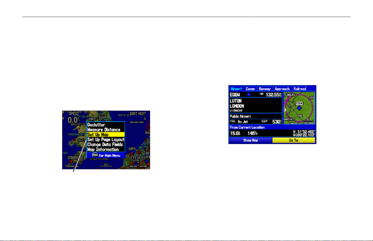
1. From the Map Page, press MENU to open the options menu.
2. Highlight Set up Map, and press ENTER.
3. Press left or right on the ROCKER to highlight the tab, then
up or down on the ROCKER to highlight the eld you want to
change, and press ENTER.
General Tab of the Map Page Setup
4. Press up or down on the ROCKER to highlight the setting,
and press ENTER to select the new setting.
5. Press PAGE or QUIT to exit.
avIatIon
GPSMAP 496 Owner's Manual 33
Page 42

AvIAtIon Mode PAges > MAP PAge
Changing the Page Layout and Data Fields
avIatIon
To customize the pages to show what you want, adjust the page
layout and data elds.
You can adjust how the following pages look on the screen: Map,
Terrain, Panel, Compass, Highway, Location Data, Trip Computer,
and optional Sonar Page. You can adjust the data elds on many of
these pages as well.
To set up the page layout:
1. Press PAGE to show the page you want to change.
2. Press MENU to open the options menu.
3. Highlight Set up Page Layout, and press ENTER.
Changing the layout of the Map Page
To change a data eld:
1. Press PAGE to show the page you want to change.
2. Press MENU to open the options menu.
3. Highlight Change Data Fields, and press ENTER
4. Move the eld highlight to the data eld you want to change,
and press ENTER.
5. Press up or down on the ROCKER to highlight the data you
want to show, and press ENTER.
6. To return the eld to the default setting, press MENU and then
ENTER.
7. Press QUIT to exit.
Changing a Data Field
4. Select the option you want, and press ENTER. The options
vary between the three usage modes and the page you are
setting up.
34 GPSMAP 496 Owner's Manual
Page 43

AvIAtIon Mode PAges > MAP PAge
Additional Map Data
You can view the data that is currently loaded on your GPSMAP 496
unit and data card.
To review or change data card information:
1. Access the Map Page, and press MENU.
2. From the options menu, highlight Map Information, and
press ENTER.
Map Family
highlighted.
Press ENTER
to view the
individual maps
in the family.
Map Card Information Page
3. The rst page shows the Map Families that are stored on the
data card and whether they are shown on the Map Page.
To change the setting for a Map Family, highlight the box next
to the Map Family name, and press ENTER to select (check
mark) or deselect (no check mark) the Show setting.
4. To view the list of maps within a Map Family, highlight the
name of the Map Family, and press ENTER.
5. To view detailed information about an individual map, highlight
the Map Name, and press ENTER. Highlight OK, and press
ENTER to exit the map information page.
6. To select or deselect individual maps, highlight the box next to
a map, and press ENTER to check or uncheck the Show box.
OR
Press MENU, and select one of the options (Show All, Hide
All, or Show Defaults), and press ENTER.
7. Press QUIT to exit the Map Information Page.
avIatIon
GPSMAP 496 Owner's Manual 35
Page 44

AvIAtIon Mode PAges > terrAIn PAge
Terrain Page
avIatIon
The Terrain Page, available only in Aviation Mode, provides an
overhead view of the terrain and obstacles beneath you. Alert
windows appear on all pages to inform you of your proximity to the
terrain and obstacles, as well as an unsafe descent rate. These alerts
depend on user-dened parameters in the Terrain setup.
Red Terrain
area: terrain
within 100 feet
of aircraft
Elevation
Scale
Terrain Page
Yellow Terrain
area: terrain
between 100
and 1000 feet of
the aircraft
Terrain Information
The areas of the terrain shaded red are predicted to be within
100 feet below or above the aircraft. The yellow terrain areas are
between the user-dened Caution Elevation and 100 feet below the
aircraft. By default, the Caution Elevation is 1,000 feet; therefore,
the areas in yellow are between 1,000 feet and 100 feet below the
aircraft. The black areas are further than the Caution Elevation. A
projected point of impact is marked with an “X” symbol.
Obstacle Information
Obstacles are shown on the Terrain Page at or below the map range
of 12 nm. Obstacles are also shown on the Map Page when the map
range is set to 3 nm or below.
Standard aeronautical chart symbols are used for lighted or unlighted
obstacles taller than 300 feet Above Ground Level (AGL). Refer to
the Obstacle Icons legend below.
Lighted Obstacle 1000 ft AGL and higher.
Unlighted Obstacle 1000 ft AGL and higher.
Lighted Obstacle below 1000 ft AGL.
Unlighted Obstacle below 1000 ft AGL.
Obstacle Icons
Each obstacle is labeled with the altitude of the top of the obstacle,
or Mean Sea Level (MSL). Each obstacle also lists, in parentheses,
the actual height of the obstacle, or Above Ground Level (AGL).
Terrain and Obstacle Color Code
Red—terrain or obstacle is within 100 feet of the aircraft.
Yellow—terrain or obstacle is between the user-dened Caution
Elevation and 100 feet below the aircraft.
36 GPSMAP 496 Owner's Manual
Page 45

AvIAtIon Mode PAges > terrAIn PAge
Alerts
If you are on another page of the GPSMAP 496 unit, Terrain,
Obstacle, and Descent Rate Alerts show in the lower-left corner to
Additional Terrain Page Options
Access the Terrain Page options menu by pressing MENU while
you are on the Terrain Page.
inform you of the situation. The alert remains on the screen until
the ight path has cleared the obstacle or terrain, or until you press
QUIT.
•
Terrain Warning
Shown on the Panel Page
•
•
•
avIatIon
Terrain Page Options Menu
Press ENTER to quickly declutter the map, just as you would
on the Map Page. See page 32.
To quickly disable alerts, highlight Disable Alerts and press
ENTER. Repeat to enable alerts again.
You can pan the map and zoom in and out using the same
techniques you use on the Map Page. See page 29.
You can change the layout of the Terrain Page. Refer to
page 36. Also, refer to page 147, for information about the
data elds.
GPSMAP 496 Owner's Manual 37
Page 46

AvIAtIon Mode PAges > terrAIn PAge
Setting Up the Terrain Page and Alerts
avIatIon
Use the Terrain Setup Page to set levels for terrain alerts as well as
obstacles in or near your ight path.
Caution Elevation
Select the Caution Elevation. If the terrain or an obstacle is within
the Caution Elevation you entered, the GPSMAP 496 provides an
alert.
Look Ahead Time
The Look Ahead Time for Terrain and Obstacle Alerts determines
the time when an alert annunciation occurs. For example, if
120 seconds is selected, the GPSMAP 496 provides an alert up to
120 seconds before you reach the terrain or obstacle.
Alert Sensitivity
The three Alert Sensitivity settings (Terrain, Obstacle, and
Descent Rate) determines what level of alerts are annunciated. The
GPSMAP 496 defaults to High sensitivity, which annunciates all
red and yellow alerts at the time set in Look Ahead Time. Medium
sensitivity annunciates all of the red and the highest priority of
yellow alerts, and Low only annunciates red alerts.
To set up the Terrain Page:
1. On the Terrain Page, press MENU to access the Terrain Page
options menu.
2. Select Set Up Terrain, and press ENTER.
Terrain Setup Page
3. To make the adjustments to the Terrain Setup, use the
ROCKER to select options, and press ENTER. Select an
option, and press ENTER.
4. Press PAGE or QUIT to accept the changes and exit the Set
up Terrain Page.
38 GPSMAP 496 Owner's Manual
Page 47

AvIAtIon Mode PAges > PAnel PAge
Panel Page
The Panel Page shows GPS-derived data in a graphical format,
similar to an instrument panel. Keep in mind the differences between
this page and your mechanical instruments, as your mechanical
panel instruments use sensors that provide information different
from that derived using GPS. The Panel Page appears only when the
GPSMAP 496 is in Aviation Mode.
The Panel Page shows a graphic Horizontal Situation Indicator
(HSI) surrounded by additional indicators.
HSI showing Course Deviation Indicator (CDI)
Ground speed
Turn rate
indicator
Estimated
time enroute
Panel Page
Next waypoint
and distance
to it
Altitude
Vertical
speed
CDI scale
The graphic HSI depicts the course to the destination or the next
waypoint in a route, current ground track, off course error, and a
To/From indication. The rotating compass indicates your current
ground track at the top of the page.
The course pointer and course deviation needle indicate the course
avIatIon
and whether you are on the course. A bug indicator provides
information to guide you back to the course if you stray off course.
If you move off course, the Course Deviation Indicator, or needle,
indicates how far off course you are, left or right, based on its
placement along the course deviation scale. To get back on course
and center the needle, steer toward the needle.
The course deviation scale setting is adjustable for Auto, ±0.25, 1.25
or 5.0 (nautical mile, statute mile, or kilometer) full-scale deection.
The course deviation scale appears on the lower right corner of
the HSI. The default setting is Auto, which uses three factors to
determine the distance from the center of the CDI to full left or right
limits:
When you are within 30 nm of any airport in the active route,
•
Auto sets the CDI scale at 1.25.
When you are on an approach leg or within 2 nm of the FAF
•
or MAP waypoints, Auto sets the scale at 0.25.
If the previous two conditions do not exist, Auto sets to 5.0.
•
GPSMAP 496 Owner's Manual 39
Page 48

AvIAtIon Mode PAges > PAnel PAge
Setting Up the Panel Page
avIatIon
You can set the bug indicator and change the CDI scale to suit your
needs.
To set a user-dened bug heading reference:
1. With the Panel Page shown, press MENU to show the Panel
Page options menu.
2. Highlight Set Bug Indicator, and press ENTER.
3. Highlight User Selected, and press ENTER. A window
appears at the center of the HSI, showing the current bug
indicator setting.
4. Select the heading reference by pressing left or right on the
ROCKER. Press ENTER. The bug indicator remains xed on
the selected heading until a new bug heading is chosen.
To change the CDI scale:
1. With the Panel Page shown, press MENU to show the Panel
Page options menu.
2. Use the ROCKER to highlight Set CDI Scale, and press
ENTER. A window appears at the center of the HSI, showing
the scale settings. The current setting is highlighted.
3. Use the ROCKER to select the scale, and press ENTER.
Manually Setting a Course
Use the Set OBS and Hold option to manually set your course to
the destination.
To manually set a course to the destination waypoint:
1. With the Panel Page shown, press MENU to show the Panel
Page options menu.
2. Highlight Set OBS and Hold, and press ENTER. An OBS
data eld appears on the screen. Keep in mind that you must
have a destination waypoint selected.
3. Select the OBS course by pressing the ROCKER left and
right. Press ENTER. The course deviation needle and course
pointer now provide steering guidance to the selected course.
To release the waypoint hold and return to automatic
sequencing of route waypoints, press MENU. Highlight
Release Hold, and press ENTER.
To cancel the OBS course and reset a direct course to the
waypoint, press Direct To , highlight Resume Route, and
press ENTER to re-start the route.
40 GPSMAP 496 Owner's Manual
Page 49

VNAV (Vertical Navigation)
VNAV Profile
Glide Ratio to Target
Distance to Target
Distance to Profile
Target Altitude
Airport
The VNAV sub tab in the Main Menu provides settings for the
vertical navigation feature. These settings create a three-dimensional
prole that guides you from your present location and altitude to a
nal (target) altitude at a specied location.
When the VNAV prole is dened, message alerts help keep you
informed of your progress. The teal bar on the HSI on the Panel
Page shows your VNAV prole.
To use the vertical navigation feature, your ground speed must be
greater than 35 knots and you must be navigating a Go To or a route.
AvIAtIon Mode PAges > PAnel PAge
avIatIon
Visual representation of VNAV
The “Approaching VNAV Prole” message appears one minute
prior to the initial descent point. The descent angle locks to prevent
changes in speed from altering the prole. The VNAV feature does
not take into account any changes in groundspeed that occur during
the transition from level ight to descent or climb.
Using the VNAV Feature
Use the VNAV (Vertical Navigation) feature to ensure that you are
ying at the proper altitude. The VNAV Indicator appears on the
HSI (Panel Page) as a horizontal teal bar, as shown in the image on
the next page. A message appears when you are approaching the
At 500 ft above the target altitude, the “Approaching Target
Altitude” message appears, the time to vertical navigation goes
blank, and the VNAV indicator disappears from the Panel Page.
CAUTION: The GPSMAP 496 is a VFR navigation tool and
GPSMAP 496 Owner's Manual 41
should not be used to perform instrument approaches. VNAV
is only a VFR navigation aid and is not intended for instrument
approaches.
VNAV Prole. When the bar is in the vertical center of the HSI, you
are at the proper altitude for the VNAV Prole. Make sure VNAV
Indicator is On in the options menu. From the Panel Page, press
MENU to open the options menu. Select Capture VNAV Prole,
and press ENTER to center or re-center the VNAV indicator on
the graphic HSI. You must have entered a valid vertical navigation
prole and be navigating.
Page 50

AvIAtIon Mode PAges > PAnel PAge
avIatIon
VNAV
Indicator
Panel Page Showing the VNAV Indicator
VNAV indicators also appear on the Map Page when the page layout
is set to Map With Overlay. You are at the proper altitude for the
VNAV prole when the blue bars are centered within the VNAV
indicators.
Target Altitude—enter the altitude you want to be at when you
reach your target location. Select Above Waypoint to use eld
elevation for airports in the Jeppesen database or Above MSL to
specify an exact MSL altitude target.
The VNAV
Waypoint
automatically
changes to
your destination
after you begin
navigating to a
destination.
VNAV Setup Tab
By—denes the target location with settings of distance Before or
After a reference waypoint (the nal destination airport). To set a
target location at a reference waypoint, enter a distance of zero.
VNAV
Indicator
VNAV Waypoint
currently active route (or Go To) as your reference waypoint. The
—allows you to select any waypoint along the
reference waypoint denes the target location.
Map Page Showing the VNAV Indicator
VNAV Prole—allows you to select the descent rate.
Setting up VNAV
To open the VNAV tab, press MENU twice to open the Main Menu.
VNAV Messages
—enables and disables VNAV alert messages.
Select Setup from the vertical tab list. Then select VNAV from the
row of tabs along the top of the page.
42 GPSMAP 496 Owner's Manual
Page 51

AvIAtIon Mode PAges > ActIve route PAge
Active Route Page
Whenever you start a route (ight plan) or initiate a Go To while
in Aviation or Marine Mode, the Active Route Page shows each
point (waypoint or map item) of the active route, with the point
name, Course, Distance, and several other elds of information. The
current destination point, the active point, is marked with an arrow.
As you navigate a route, the list automatically updates to indicate the
active point rst. The Active Route and Route Review Pages share
many of the same features and options.
Press PAGE repeatedly to open the Active Route Page.
Active Route Page
NOTE: If you have created a route (Flight Plan) with a Jeppesen
point that is no longer current after you perform an update to
your Jeppesen Database, the route is locked. You need to create a
new route with current Jeppesen Database points.
Active Route Page Options
Press MENU while on the Active Route Page to open the options
menu. You can edit the route using many of the options in the menu
such as Edit on Map (see page 72 for information), Add Waypoint,
and Invert. You can also change the data elds to suit your needs.
You can also select an approach for your landing and set your fuel
ow (or plan your route, based on your current Usage Mode):
Select Approach—(Aviation Only) allows you to select the
nal course segment of a published approach, replacing the
nal destination airport in a Go To or route with the sequence of
waypoints for the selected approach. The approaches provide only
the nal course segment, usually from nal approach x (FAF)
to missed approach point (MAP), and are based on existing GPS,
RNAV, VOR, NDB, localizer, or ILS approach procedures. All
approach procedures are own as a sequence of waypoints in the
route. To select an approach and add the waypoints to the route,
the nal destination in the Go To or route must be an airport with a
published approach.
Set Fuel Flow (Plan Route)—allows you to enter information about
your aircraft and route.
avIatIon
GPSMAP 496 Owner's Manual 43
Page 52

AvIAtIon Mode PAges > PosItIon dAtA PAge
Position Data Page
avIatIon
The Position Data Page provides a quick reference for the important
data you want to show while navigating a route in Aviation and
Marine Modes. The default page shows a compass ribbon, your
current latitude and longitude, the current date and time, your
location in reference to the nearest landmark, and eight user-
selectable data elds. The compass ribbon is shown at the top of the
page to show your current heading with a red, vertical bar. To stay
on course, steer toward the violet bar (or arrows) until it is aligned
with the red bar.
Press PAGE repeatedly to open the Position Data Page.
Position Data Page
Airport is selected as the Nearest Type. The Craneld (EGTC) airport is the
nearest airport, and you are 4.1 nm NW of EGTC.
Position Data Page Options
With the Position Data Page open, press MENU to open the options
menu. You can set up the layout of the page and change the data
elds. For an explanation of the data elds, refer to page 147. You
can also select one of the following options:
Change Nearest Type—allows you to specify the type of item to
be used as the nearest item (shown in the lower-left data eld). The
choices differ based on the Usage Mode you are currently using.
Choose Automatic to allow the unit to pick the appropriate type of
landmark for your present location.
Reset Trip
the odometer.
Reset Max Speed
Reset Odometer
since the odometer was last reset.
Reset All
and odometer.
—clears trip information, except the maximum speed and
—clears the maximum speed.
—clears the running total of the distance traveled
—clears all trip information including the maximum speed
44 GPSMAP 496 Owner's Manual
Page 53

AvIAtIon Mode PAges > flIght log
Flight Log
The Flights tab shows a list of any recorded ights, including date,
route of ight, and ight time. The GPSMAP 496 saves up to 50
recorded ights while in Aviation Mode. Entries on this list are
To view details for a ight:
1. Press MENU twice to open the Main Menu.
2. Highlight Flights from the vertical menu of tabs.
3. Press MENU and select Show Hours and Minutes to view
automatically created for each ight.
The bottom of the Flights tab shows the time of your last ight. This
4. Highlight the ight, and press ENTER. The ight details
resets if you select All Unit Defaults from the System tab options
menu.
5. With OK highlighted, press ENTER to return to the Flights tab.
An optional FlightBook software package is available to further
simplify your ight record keeping. For details about FlightBook,
visit the Garmin Web site at www.garmin.com/aviation.
Viewing the Flight Log
Recording begins when your speed exceeds 30 knots and you
gain 250 feet of altitude. The Route of Flight eld uses the
nearest airport as the departure airport. The destination airport is
continuously updated as your ight progresses.
If you land and groundspeed drops below 30 knots, the ight entry
is saved and a new entry is recorded when you depart the airport.
A touch-and-go or brief stop of less than 10 minutes appends to the
current ight record, rather than starting a new entry.
Select any listed entry in the log to view additional information.
Deleting Flight Records
You can delete the highlighted ight record (Delete Flight) or delete
all ight records from the Flight Log (Delete All). To delete ights,
press MENU (with the Flights tab information shown). Use the
ROCKER to highlight a menu option, and press ENTER.
the ights in minutes and hours, if you prefer.
window opens, shown below.
Flight Tab
Showing the ight details page
avIatIon
GPSMAP 496 Owner's Manual 45
Page 54

AvIAtIon Mode PAges > AIrcrAft InforMAtIon
Aircraft Information
avIatIon
The Aircraft tab is divided into two sub tabs: Aircraft Prole and
Weight & Balance.
To open the Aircraft tab:
1. Press MENU twice to open the Main Menu.
2. Highlight Aircraft from the vertical list of tabs.
3. Press the ROCKER right or left to highlight either the Aircraft
Prole tab or the Weight & Balance tab from the top of the
screen.
Aircraft Prole Tab
Entering Your Aircraft Prole
The Aircraft Prole tab allows you to prole cruising speed,
maximum speed, fuel ow, and map symbol. The unit can save up to
10 aircraft proles.
Cruising speed and fuel ow are used as default settings when
viewing trip planning information on the Route Review Page. The
maximum speed is used to dene the range for airspeed on the Panel
Page and is automatically updated if you exceed this gure.
To enter an aircraft prole:
1. From the Aircraft Prole tab, use the ROCKER to highlight
New, and press ENTER.
2. Highlight the Current Aircraft eld, and press ENTER.
OR
Highlight the Rename button, and press ENTER.
3. Use the ROCKER to enter the aircraft tail number (or other
identifying information) in the Current Aircraft eld. Press
ENTER when nished.
4. Use the ROCKER to enter information for the cruising and
maximum speeds for your aircraft, your aircraft’s fuel ow, and
the symbol for your aircraft.
Select a symbol for your aircraft to change the data elds on
the Panel Page and the map symbol.
To select a saved aircraft prole:
1. From the Aircraft Prole tab, use the ROCKER to highlight the
Current Aircraft eld, and press ENTER.
2. Use the ROCKER to select the aircraft prole, and press
ENTER.
46 GPSMAP 496 Owner's Manual
Page 55

To rename or delete a saved aircraft prole:
1. From the Aircraft Prole tab, use the ROCKER to highlight
Current Aircraft and select the prole you want to rename.
2. Use the ROCKER to select the on-screen Rename or Delete
button, and press ENTER. If Rename is selected, use the
ROCKER and ENTER keys to enter a new tail number.
AvIAtIon Mode PAges > AIrcrAft InforMAtIon
avIatIon
Calculating the Weight & Balance
Weight & Balance Tab
Weight & Balance may be used during your pre-ight preparations
to verify the weight and balance conditions for your aircraft. By
entering the weight and arm values on this page, the GPSMAP 496
can calculate the total weight, moment, and center of gravity (CG) to
ensure a safe ight.
Before entering the various gures, you need to determine the
empty weight of the airplane and the arm (or “station”) for each
weight entered. These gures should be determined using the pilot’s
operating handbook for your airplane, which also notes the weight
limitations and fore/aft CG limits. Compare those gures to the
values calculated by the GPSMAP 496.
To perform weight and balance calculations:
1. Press MENU twice to open the Main Menu.
2. Highlight Aircraft from the vertical list of tabs.
3. Press the ROCKER right to highlight Weight & Balance.
GPSMAP 496 Owner's Manual 47
4. Highlight the weight eld, and press ENTER.
5. Use the ROCKER to enter the weight gure. Press ENTER.
6. Change the weight units. Highlight lbs, and press ENTER.
OR
Select Kgs, and press ENTER.
7. Highlight the corresponding ARM eld, and press ENTER.
8. Use the ROCKER to enter the arm gure. Press ENTER.
9. Repeat steps 4 through 8 until all gures are entered. The
calculated moment, weight, and CG gures appear at the
bottom of the page. Keep in mind that the “Aircraft” (empty
weight/arm) gures must be entered as a reference to
calculate a valid moment, weight, and CG.
10. To empty the aircraft, press MENU, select Empty Aircraft,
and press ENTER.
NOTE: This information is only for ight planning purposes.
Consult your aircraft’s pilot handbook for the ofcial weight and
balance data.
Page 56

AvIAtIon Mode PAges > e6b tAb
E6B Tab
avIatIon
The E6B tab in the Main Menu calculates Density Altitude, True
Airspeed, and Winds Aloft (Head Wind, Tail Wind, Wind From, and
Wind Speed), based on information you enter.
To open the E6B tab of the Main Menu:
1. Press MENU twice to open the Main Menu.
2. Highlight E6B from the vertical list of tabs.
Calculated
gure
Calculated or
user-entered
gure
E6B Tab
Indicated Altitude—required entry for density altitude/true airspeed
calculation. Enter the aircraft’s altimeter reading.
Calibrated Airspeed
—required entry for density altitude/true
airspeed calculation. Enter the aircraft’s airspeed indicator.
Barometric
pressure
Calculated
gures
Baro Pressure
—required entry for density altitude/true airspeed
calculation. Use current altimeter setting (barometric pressure).
Total Air Temperature
—required entry for density altitude/true
airspeed calculation. Total Air Temperature (TAT) is the temperature
of the air including the heating effect caused by speed. The
temperature reading on a standard outside air temperature gauge
found on most piston aircraft is TAT.
Head Wind—(calculated gure) determined from entry of heading
and true airspeed.
Wind From—(calculated gure) determined from entry of heading
and true airspeed.
Wind Speed—(calculated gure) determined from entry of heading
and true airspeed.
True Airspeed—
(calculated or user-entered gure) determined from
entry of calibrated airspeed, baro pressure, and total air temperature.
Also can be entered directly for winds aloft calculations.
Density Altitude—
(calculated gure) determined from entry of
indicated altitude, barometric pressure and total air temperature.
Heading—required entry for winds aloft calculation. Use heading
from the aircraft’s heading indicator or directional gyro.
48 GPSMAP 496 Owner's Manual
Page 57

AvIAtIon Mode PAges > e6b tAb
To calculate true airspeed and density altitude:
1. From the E6B tab, highlight the Indicated Altitude eld (at
the top of the page), and press ENTER.
2. Use the ROCKER to enter the altitude shown on your
altimeter. Press ENTER when nished.
3. Repeat steps 1 and 2 to enter the Calibrated Airspeed,
Baro Pressure, and Total Air Temperature. (For Calibrated
Airspeed, use the speed shown on your airspeed indicator.
Use the current altimeter setting for Baro Pressure. Total Air
Temperature is the temperature of the outside air including
the heating effect caused by speed. For most aircraft,
this is the temperature reading on a standard outside air
temperature gauge.) The calculated gures for True Airspeed
and Density Altitude are shown in the designated elds.
To calculate winds aloft:
1. Follow the steps in the previous procedure to determine true
airspeed.
OR
Use the ROCKER and ENTER keys to manually enter a true
airspeed gure in the True Airspeed eld.
2. Use the ROCKER to highlight the Heading eld, and press
ENTER.
3. Use the ROCKER to enter the aircraft heading shown on your
directional gyro or compass. Press ENTER when nished.
The calculated gures for Head Wind, Wind From, and Wind
Speed appears.
NOTE: If a True North reference is currently selected as the
heading reference on your GPSMAP 496, you must enter
Heading using a True North reference to determine winds
accurately.
avIatIon
To restore defaults on the E6B tab:
1. Open the E6B tab on the Main Menu.
2. Press MENU to open the options menu.
3. Highlight Restore Default, and press ENTER.
GPSMAP 496 Owner's Manual 49
Page 58

bAsIc oPerAtIon In AutoMotIve Mode > AutoMotIve Mode PAge sequence
BaSIc operatIon In autoMotIve Mode
To switch usage modes:
1. Press and hold PAGE/MODE.
2. Use the ROCKER to select either Aviation, Automotive, or Marine, and press ENTER.
Automotive Mode Page Sequence
autoMotIve
Automotive Mode features two main pages: the Map and Trip Computer Pages. Optional Highway and Compass Pages can be enabled in
Automotive Mode. Two additional pages appear during active navigation while in Automotive Mode—a Current Route Page appears if you
are navigating a turn-by-turn route, and an Active Route Page appears if you are navigating “Off Road.” See “Navigating in Automotive
Mode” beginning on the next page for more information.
Trip Computer Page Map Page Compass Page
(Optional)
Highway Page
(Optional)
Current Route Page
To add the Compass or Highway Pages:
1. Press MENU twice to show the Main Menu. Use the ROCKER to highlight the Display tab.
2. Highlight the Highway Page or Compass Page elds, and press ENTER. Select On, and press ENTER.
50 GPSMAP 496 Owner's Manual
Page 59
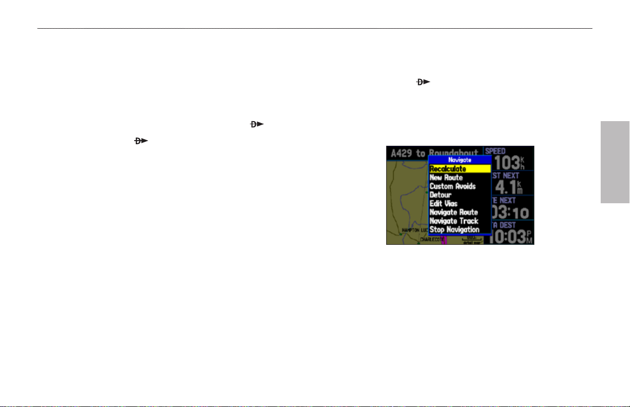
bAsIc oPerAtIon In AutoMotIve Mode > nAvIgAtIng In AutoMotIve Mode
Navigating in Automotive Mode
Automotive Mode and Marine Mode are similar. Most of the
To go to a highlighted map item:
1. Use the ROCKER to highlight the item you would like to
features discussed here also apply to Marine Mode.
There are several ways to begin navigating to a point in Automotive
2. Press Direct To . Go To <point name> is added to the list
Mode:
Select a point on the map and press Direct To .
•
Press Direct To to start a new route using the Find menu,
•
or start a saved route or track.
Press NRST/FIND to search for a particular item and create a
•
route to it.
You can also start a saved route through the Routes tab on the Main
Menu. For more information, refer to page 56.
3. Follow the magenta route created on the Map Page. Follow
navigate to on the Map Page.
of options and automatically highlighted. If you have selected
an area of the map that is not a map feature, Go To MAP
Point is listed. Select Go To <point name> or Go To MAP
Point, and press ENTER.
autoMotIve
Navigate Options in Automotive Mode
With Map Feature highlighted while navigating a course
the turn-by-turn route (auto-route) by using the Next Turns
Page and Current Route Page. If you are using the external
speaker, follow the voice prompts.
GPSMAP 496 Owner's Manual 51
Page 60

bAsIc oPerAtIon In AutoMotIve Mode > nAvIgAtIng In AutoMotIve Mode
autoMotIve
To start new route using the Find Menu:
1. Press Direct To to open the Navigate menu.
2. Highlight New Route (or Go To Point when in Marine Mode),
and press ENTER to open the Find Menu.
3. From the Find Menu, highlight Waypoints, and press ENTER.
(You can also choose to go to other points, such as Cities or
Services from this list. The steps vary only slightly from those
listed for Waypoints.)
4. Select a waypoint from the list, and then press ENTER to
show the Waypoint Page.
Waypoint Page
Activating a Go To using the Find Menu
5. The Waypoint Page automatically opens. With the Go To
button highlighted, press ENTER to begin navigation.
To search for an item and route to it:
1. Press NRST/FIND to open the Find Menu.
2. Using the ROCKER, highlight a category, such as
Food & Drink, and press ENTER.
3. Press ENTER and use the ROCKER to begin entering the
letters contained in the item name. The list begins to sort
by the items that contain the letters you are entering. Press
ENTER.
Finding an item using the Containing eld: The unit searches for items
containing the letter combination you enter and shows them in the list.
4. Highlight an item from the list, and press ENTER.
5. Highlight the Go To button, and press ENTER.
For complete information about nding an item, refer to page 53.
52 GPSMAP 496 Owner's Manual
Page 61

bAsIc oPerAtIon In AutoMotIve Mode > fIndIng An IteM
Finding an Item
The Find Menu allows you to easily search the stored waypoints and
points of interest. Press NRST/FIND to access the Find Menu.
The Find Menu is comprised of several default categories such as
Waypoints, Cities, Exits, Addresses, Crossroads, Food & Drink,
Using the Find From Feature
The Find option also supports a “nd from” feature that allows you
to center your search around an item that you have just found.
To nd an item from another location on the map:
1. Open the Map Page. Use the ROCKER to pan the arrow
Attractions, Aviation Points, Transportation, and Weather Data.
Find Menu
Follow the directions on the previous page to search for an item near
2. The Find Menu opens showing “From Map Pointer.” The list
your current location and then route to it.
3. Using the ROCKER, highlight an item from the list, and press
(pointer) to the location you want, and press NRST/FIND.
autoMotIve
Find From Map Pointer
of items is sorted to show items nearest the selected location.
Using the ROCKER, highlight the category you want from the
list, and press ENTER.
ENTER. The item’s information page automatically opens,
allowing you to save the item as a waypoint, show the item on
the map, or automatically create a route to (Go To) the item.
GPSMAP 496 Owner's Manual 53
Page 62

bAsIc oPerAtIon In AutoMotIve Mode > fIndIng An IteM
autoMotIve
To nd an item from another location:
1. From any page, press NRST/FIND.
2. Using the ROCKER, highlight the category you want from the
list, and press ENTER.
3. Press MENU. Highlight Near Other, and press ENTER. If you
are actively following a route, you can also choose one of the
other options listed in the Find From list, as shown below.
Find From Options
4. Select a reference location on the map, and press ENTER.
The list shows items near the new map location.
To nd an item near another item:
1. Press NRST/FIND.
2. From the Find Menu, highlight the item you want to Find
From.
3. Press NRST/FIND with the item highlighted. The Find Menu
opens again with items near the previously selected item.
Search for the item.
Recently Found Items
The Recently Found Page shows a list of the items you have
searched for or gone to recently.
To view recently found items:
1. Press NRST/FIND. The Find Menu opens.
2. Use the ROCKER to highlight Recently Found. Press
ENTER. The Recently Found Page opens.
3. Press MENU to show the options menu:
Show Find History—allows you to toggle between showing the
items you have searched for recently (Find History) and the items
you have recently created a Go To for (Go To History).
Remove Point
—removes the point that is highlighted in the list.
54 GPSMAP 496 Owner's Manual
Page 63

bAsIc oPerAtIon In AutoMotIve Mode > fIndIng An IteM
Viewing the Information Page
Each item on the map and each item listed in the Find Menu results
list has an information page.
To view details about an item:
1. Highlight a point on the map or in the search results list, and
press ENTER.
An Information Page appears with details about the item in a
tabbed format. Based on the type of item, additional options
are available for viewing the item on the map viewing the list
of maps on your data card, and viewing the next item in the
search results list.
Find Menu Options
To view additional options for the Find Menu, press NRST/FIND,
and then press MENU.
Enable Auto Arrange
Disable Auto Arrange and Restore Default options appear when
you select Enable Auto Arrange.
Near Other
compile the Find items lists. Using the ROCKER, move the map
arrow to a location, and press ENTER.
Map Information
stored on the data card and allows you to select which maps are
showed on the Map Page.
Additional selections are included in the options menu when you are
navigating:
Near Next
the route.
Information Page
Near Destination
destination.
2. Press PAGE or QUIT to exit the information page. You can
also highlight one of the on-screen buttons, and press ENTER
to perform that operation.
Near Current Route
active route.
—automatically arranges the Find Menu.
—allows you to select a new location from which to
—shows information about the detailed map data
autoMotIve
—compiles the Find items lists based on the next turn in
—compiles the Find items lists based on the route
—compiles the Find items lists based on the
GPSMAP 496 Owner's Manual 55
Page 64

bAsIc oPerAtIon In AutoMotIve Mode > creAtIng routes
Creating Routes
The GPSMAP 496 lets you create and store up to 50 reversible
routes, with up to 300 waypoints each.
Routes can be created in two ways. The rst way is to select
waypoints from the Find Menu, allowing you to see a list of the
route points as you create the route. The second way is by selecting
autoMotIve
waypoints or map items from the Map Page, allowing you to see
each route point graphically on-screen as you create the route.
Route Tab
To create a route using the Find Menu:
1. Press MENU twice to show the Main Menu.
2. Use the ROCKER to highlight Route from the vertical list
of tabs.
3. Press MENU to show the Route options menu. Select New
Route, and press ENTER.
OR
Highlight the rst available blank route slot and press ENTER.
The Route Review Page automatically opens, showing a
blank route.
4. Press ENTER to nd items to add to the route.
5. The Find Page or Find Menu opens (based on which Usage
Mode you are in). Using the methods discussed in the
“Finding an Item” section beginning on page 53, select a point
to add to your route. When you nd an item, highlight OK, and
press ENTER to add the point to the route. Repeat until you
have added all of the points to the route.
Creating a New Route on Route Review Page
56 GPSMAP 496 Owner's Manual
Page 65

bAsIc oPerAtIon In AutoMotIve Mode > creAtIng routes
To create a route graphically:
1. Press MENU twice to show the Main Menu. Use the ROCKER
to highlight Route from the vertical list of tabs.
2. Press MENU to show the Route options menu. Select New
Route, and press ENTER.
3. Highlight the rst blank slot in the Route List Page, and press
MENU. Use the ROCKER to highlight Edit on Map, and
press ENTER.
4. Use the ROCKER to highlight the location, and press ENTER.
Press MENU and select Append To Route.
If you select an area of the map that is not a feature or
waypoint, a new waypoint is created for that location. Press
ENTER on the New Waypoint Page to save the location as
a waypoint and continue adding points to your route. You
can edit the properties of this waypoint as you can with any
waypoint.
5. Repeat until you have added all points to the route.
6. When nished, press QUIT twice to return to the Route
To follow a saved route in Automotive Mode:
1. Press MENU twice to show the Main Menu. Use the ROCKER
2. Highlight the route you want to start, and press MENU.
3. Highlight Activate Route, and press ENTER.
4. The Active Route Page opens. Press MENU. Highlight Follow
Review Page.
OR
Press MENU, highlight Edit as Text, and press ENTER to
view the Route Review Page.
to highlight Route from the vertical list of tabs.
Roads, and press ENTER. The GPSMAP 496 automatically
generates a turn-by-turn route following roads.
autoMotIve
Creating a New Route on the Map
GPSMAP 496 Owner's Manual 57
Page 66

bAsIc oPerAtIon In AutoMotIve Mode > creAtIng WAyPoInts
Creating Waypoints
Waypoints are locations or landmarks you record and store in your
GPSMAP 496. Save your current location as a waypoint by pressing
and holding ENTER/MARK. You can also nd waypoints using the
map or Find Menu and store them in the unit.
The GPSMAP 496 stores up to 3,000 alphanumeric waypoints
autoMotIve
with a user-dened icon, category, comment, altitude, depth, and
temperature available for each waypoint. Waypoints can be created
using three basic methods:
ENTER/MARK
•
—allows you to quickly mark your present
Marking Your Present Location
The ENTER/MARK key lets you quickly capture your present
location to create a new waypoint. You must have a valid location
(2D or 3D) x to mark your present location. You can determine the
satellite x by looking at the GPS tab on the Main Menu.
To mark your present location:
1. Press and hold ENTER/MARK until the New Waypoint Page
appears, then release it. A default four-digit name and symbol
are assigned for the new waypoint.
location.
•
Graphically
—allows you to dene a new waypoint location
from the map show using the ROCKER.
•
Text Entry
—allows you to enter a new waypoint’s location
coordinates manually.
New Waypoint Page
2. To accept the waypoint with the default information, use the
ROCKER to highlight OK, and press ENTER.
3. To change any information on the New Waypoint Page,
highlight the appropriate eld, and press ENTER. After
entering and conrming your changes, highlight OK, and
press ENTER.
58 GPSMAP 496 Owner's Manual
Page 67

Creating Waypoints From the Map
You can create a waypoint using the Map Page. When you pan the
map and move the arrow over a map item, a highlighted description
of that item appears. The GPSMAP 496 uses the map item text
shown on the map as the default name and symbol for the new
waypoint.
bAsIc oPerAtIon In AutoMotIve Mode > creAtIng WAyPoInts
To create a new waypoint using the Map Page:
1. Press PAGE until the Map Page appears.
2. Use the ROCKER to move the arrow to the map location or
map feature.
3. Press and quickly release ENTER/MARK to capture the arrow
location. Pressing and holding ENTER/MARK marks your
present location, not the arrow’s location.
If you have highlighted a map feature, an information page
appears after you press ENTER. Use the ROCKER to
highlight Save, and press ENTER to save the item as a
waypoint. The New Map Waypoint Page appears.
GPSMAP 496 Owner's Manual 59
4. To accept the waypoint with the default information, highlight
OK, and press ENTER.
To change the any information on the New Map Waypoint
Page, highlight the appropriate eld, and press ENTER. After
entering your changes, highlight OK, and press ENTER.
Map Feature Information Page
Select Save to save the map feature as a waypoint
autoMotIve
Page 68

bAsIc oPerAtIon In AutoMotIve Mode > creAtIng WAyPoInts
Creating a Waypoint by Entering Coordinates
You can manually enter location coordinates to create a waypoint.
This method is useful for creating a waypoint at a specic latitude/
longitude location from a chart. You can manually change the
location coordinates in the New Waypoint Page to create a new
waypoint or use the Create Waypoint selection in the User Points
autoMotIve
tab options menu.
To create a new waypoint by entering location
coordinates:
1. Press and hold ENTER/MARK to create a waypoint (or use
your favorite method discussed in previous sections). The
new waypoint is created with the next available waypoint
number and the receiver’s last known location as the default
location.
60 GPSMAP 496 Owner's Manual
2. On the New Waypoint Page, use the ROCKER to highlight the
3. To change any of the other information, highlight the
4. After entering your changes, highlight OK, and press ENTER.
To change the location of a waypoint, highlight the
character you want to change in the Location eld.
Press up or down on the ROCKER to change the
character. Repeat until the new location is entered.
Location eld, and press ENTER. Use the ROCKER to enter
the location coordinates, and press ENTER when nished.
appropriate eld, and press ENTER. Use the ROCKER to
enter the new information.
Page 69

bAsIc oPerAtIon In AutoMotIve Mode > folloWIng An AutoMotIve route
Following an Automotive Route
The GPSMAP 496 guides you to your destination using many tools,
such as the Map Page and Current Route Page.
Track Your Progress with the Map Page
You can track the progress of your route on the Map Page. Your
route is shown with a magenta line. The next turn appears in the top
bar on the Map Page.
Map Page Displaying Your Route
Watch Your Trip Data
Use the Trip Computer Page to view your trip data. You can track
your speed, as well as other information related to your trip.
Current Route Page in Automotive Mode
Whenever you have started a turn-by-turn route in the GPSMAP 496
set in Automotive Mode, the Current Route Page shows each turn of
the active route, with the distance to the turn, the street name, and
estimated time to arrival and time of arrival. As you navigate a route,
the next turn appears at the top of the list.
Starting and Stopping Navigation
Press Direct To to open the Navigate menu. Highlight
Stop/Resume Navigation.
autoMotIve
Current Route Page
GPSMAP 496 Owner's Manual 61
Page 70

bAsIc oPerAtIon In AutoMotIve Mode > edItIng your route
Editing Your Route
When you are navigating a route, you can edit that route. You can
add areas and roads to avoid as well as temporary detours to your
current route. You can also add stops along your trip, called Via
Points.
While navigating, press Direct To to open the Navigate Menu,
autoMotIve
shown below.
Navigate Options in Automotive Mode
While navigating a course
Entering Custom Avoids
Custom Avoids allows you to enter specic areas and roads that
you would like to avoid in your navigation. Custom Avoids apply
to all routes, but Detours apply to only the active route. Custom
Avoids can be added while you are navigating a route or before you
navigate.
To enter a custom avoid:
1. Press Direct To while in Automotive Mode.
OR
Open the Map Page, and press MENU.
2. Select Custom Avoids. Press ENTER.
3. Press ENTER when the Add Avoid button is highlighted.
4. Select Avoid Road or Avoid Area, and press ENTER.
5. Use the ROCKER to move the arrow to the rst point in the
avoidance area. Press ENTER to select the rst point.
6. Move the arrow to the end point and press ENTER. During
route calculation and navigation, the GPSMAP 496 avoids the
area within the box or the selected area of the road.
7. When nished, highlight the OK button, and press ENTER.
62 GPSMAP 496 Owner's Manual
Page 71

bAsIc oPerAtIon In AutoMotIve Mode > edItIng your route
Creating a Detour
If, while navigating a route, there is road construction or a closed
road, you can have your GPSMAP 496 create a detour route. While
navigating a course, press Direct To . Select Detour from the
Navigate menu. Select the distance you want, and press ENTER.
The GPSMAP 496 recalculates your course based on your detour
distance. To end the detour manually, press Direct To again and
select Cancel Detour.
Adding and Editing Stops (Via Points)
You can add Via Points—points through which you would like to
travel—to your route using the Edit Vias option. Via points are great
for adding a stop at the gas station or bank to your route and are
really helpful when planning a long trip.
Add/Edit Vias Page
Showing the original route without via points
To add Via Points to your route:
1. While navigating your route, press Direct To to open the
Navigate menu.
2. Use the ROCKER to select Edit Vias, and press ENTER.
3. The Add/Edit Vias window opens. Press ENTER with Add Via
Point highlighted.
4. From the window, highlight either Use Map or Find and press
ENTER.
5. If you selected Use Map, use the ROCKER to select an item
on the map and press ENTER.
If you selected Find, select an item from the Find Menu as
discussed in the “Finding an Item” beginning on page 53.
Remember you can press MENU while the Find Menu is
open to nd an item near another location, such as your
destination.
6. The new point is added to the route and appears in the Add/
Edit Vias Page. Continue steps 2 through 4 until you have
added all of the Via Points that you want. Highlight Done, and
press ENTER to apply the new Via Points to the route.
autoMotIve
GPSMAP 496 Owner's Manual 63
Page 72

AutoMotIve Mode PAges And feAtures > MAP PAge
autoMotIve Mode paGeS and FeatureS
This section discusses the major pages in Automotive Mode, such
as the Map Page, as well as some additional features, such as routes
and points.
Map Page
autoMotIve
Refer to pages 28–35 in the “Aviation Mode Pages” section for more
details about the Map Page.
Current
location
Map Page
Data elds
Map zoom
range
The location marker (icon) that shows your travel on the Map Page
is a triangle symbol in Marine and Automotive modes. The
GPSMAP 496 always turns on in location mode, with the last known
location centered on the map. When you press the ROCKER, the
Press the zoom keys (IN and OUT) to change the map range. Some
items on the map appear only if the map is zoomed in to a certain
level.
Press MENU to open the options menu for the Map Page.
GPSMAP 496 enters pan mode, which moves the map to keep the
white arrow (map pointer) within the screen area.
Enter Custom Avoids so your routes does not include areas you
would like to avoid, such as high trafc areas.
In Automotive Mode, by default, four user-selectable data elds
appear on the right side of the screen that can be congured to show
any one of the possible data options. The top of the screen shows the
GPS status or the route leg. You can also add additional data elds to
Use the ROCKER to measure the distance between two objects on
the map.
Change the page layout and data elds to customize the Map Page.
the page or select a full screen map without data elds.
64 GPSMAP 496 Owner's Manual
Page 73

AutoMotIve Mode PAges And feAtures > hIghWAy PAge
Highway Page
The Highway Page is only available in Marine Mode and
Automotive Mode. In Automotive Mode, the Highway Page is
not shown by default. See the directions to the right to show the
Highway Page.
Using the Highway Page
To stay on course, steer toward the violet bar (or arrows) until
it lines up with the red bar in the middle. The bottom section of
the screen provides visual guidance to the waypoint on a graphic
highway. The line down the center of the highway represents your
track line.
As you head toward your destination, the highway perspective
Highway Page
When you are navigating, the Highway Page provides digital and
graphic steering guidance to the destination. The right side of the
Highway Page features user-selectable data elds showing useful
navigation information. A compass ribbon appears at the top of
the page to show your current heading as the violet bar and a red
vertical bar indicates the bearing to your course.
moves to indicate your progress to the waypoint and which direction
you should steer to stay on course. If you are navigating a route, the
Highway Page shows each route waypoint in sequence connected
by a black “road” with a white line down the middle, which is your
track line. Nearby waypoints not in the active route can also be
shown. You can zoom in or out to show a larger or smaller view of
the highway.
To hide/show the Highway Page:
1. Press MENU twice to show the Main Menu.
2. Use the ROCKER to highlight the Display tab.
3. Highlight the Highway Page eld, and press ENTER.
4. Select Off to hide or On to show, and press ENTER.
To change the highway perspective scale:
Press IN to zoom in.
•
Press OUT to zoom out.
•
autoMotIve
GPSMAP 496 Owner's Manual 65
Page 74

AutoMotIve Mode PAges And feAtures > hIghWAy PAge
Highway Page Options
The Highway Page options menu allows you to dene the data elds
and select which waypoints and track are shown on the screen. The
data elds, located along the right side of the page, provide a user-
selectable layout of various types of useful data. The layout can also
be changed to show additional data elds.
autoMotIve
To show and select the Highway Page Options:
1. Press PAGE repeatedly until the Highway Page appears.
2. Press MENU.
3. Use the ROCKER to highlight the option.
4. Press ENTER.
Highway Page Options Menu
The following options are available from the Highway Page menu:
Set up Page Layout—allows you to choose the number of data
elds.
Change Data Fields—allows you to specify the type of data shown
in each data eld used on the map screen. This option is available
from any of the main pages. See the “Appendix” for a listing of the
data elds.
Set Up Highway—shows an options menu with two tabs: Line and
Waypoint. Each tab has On/Off settings for several options, such as
enabling the line for the Active Leg and Track Log.
Set Up Highway
66 GPSMAP 496 Owner's Manual
Page 75

Current Route Page
Whenever you have started a route in the GPSMAP 496 in
Automotive Mode, the Current Route Page shows each turn of the
active route, with the distance to the turn, the street name, and the
estimated time to arrival and time of arrival. As you navigate a route,
the turn list automatically updates to indicate the next turn at the top
of the list.
Saving the Current Route
You can save the current route from the Current Route Page. Press
MENU to save the route. Press ENTER when Save Route is
highlighted. Your route is automatically saved, using the starting
point and destination as the route name. Highlight OK and press
ENTER to complete saving the route.
Current Route Page
You can scroll through the entire list by pressing the ROCKER up
or down. Highlight any of the turns on the list and press ENTER
to view the Next Turn Page for that turn. The Current Route and
Next Turn Page screen show similar information, just in a different
layouts. The Next Turn Page shows your next turn on a map.
AutoMotIve Mode PAges And feAtures > current route PAge
Next Turn Page
autoMotIve
GPSMAP 496 Owner's Manual 67
Page 76

AutoMotIve Mode PAges And feAtures > trIP coMPuter
Trip Computer
The Trip Computer Page provides a quick reference for the
important data you want to show while navigating a route in
Automotive Mode. It indicates your current speed and many helpful
statistics about your trip, such as bearing, average speed, and
moving time.
autoMotIve
Reset the Trip Computer before beginning a trip. If you make
frequent stops, leave the GPSMAP 496 turned on to allow the unit to
accurately measure elapsed time during the trip.
Trip Computer Page
Trip Computer Page Options
Press MENU while on the Trip Computer to show the options menu.
The following options are available from the Trip Computer Page.
Some options are only available if you have changed the page layout
from the default.
Set Up Page Layout
of data elds. You can also select a graphical Dashboard, select to
show the Position Data Page layout (2 Columns), or select 4 Big
Fields as the layout of the page. You can change the Data Fields on
the 2 Columns and 4 Big Fields layout pages.
Change Nearest Type—allows you to specify the type of item to
be used as the nearest item (shown in the lower-left data eld of the
Position Data (2 Columns) layout). The choices differ based on the
Usage Mode you are currently using.
Reset Trip
the odometer.
Reset Max Speed
Reset Odometer
Reset All
and odometer.
—clears trip information, except the maximum speed and
—clears all trip information including the maximum speed
—allows you to choose the layout and number
—clears the maximum speed.
—clears the running total of the distance traveled.
68 GPSMAP 496 Owner's Manual
Page 77

AutoMotIve Mode PAges And feAtures > edItIng And MAnAgIng routes
Editing and Managing Routes
The Route tab shows the routes you have created in your
GPSMAP 496 unit. For complete information on routes, refer to the
“Creating Routes” section beginning on page 56.
Viewing All of Your Saved Routes
The Route tab in the Main Menu lists all of your saved routes on one
easy-to-read Route List.
Route Tab
To view the route list:
1. Press MENU twice to open the Main Menu.
2. Highlight Route from the vertical menu of tabs using the
ROCKER.
Using the Route Options
The Route tab in the Main Menu shows all the routes currently
stored in memory, along with a descriptive name for each route.
Highlight a route, and press MENU to open the options menu.
From here you can start the route, copy it, delete it, delete all routes,
and create a new route. You can also set up the routes to manually
transition to the next waypoint.
Manually Transitioning to the Next Waypoint
From the Route tab Option Menu, highlight Set Up Routes, and
press ENTER to set the route leg transition (or waypoint transition).
Select Distance to enter a radius so that when you are within the
entered distance, the GPSMAP 496 leads you to the next point on
your route.
When you select Manual, you can transition to the next waypoint
while navigating a route. While you are navigating the route,
open the Active Route Page. Press MENU. Highlight Next Route
Waypoint, and press ENTER to have the GPSMAP 496 start
routing you to the next point in your route.
autoMotIve
GPSMAP 496 Owner's Manual 69
Page 78

AutoMotIve Mode PAges And feAtures > edItIng And MAnAgIng routes
Navigating a Saved Route
The Navigate Route option allows you to easily select a saved route.
For information about creating routes, refer to the “Creating Routes”
section beginning on page 56.
To navigate a route in Automotive Mode:
autoMotIve
1. In Automotive Mode, press Direct To .
2. Use ROCKER to highlight Navigate Route, and press
ENTER.
3. Highlight a route, and press ENTER. The Active Route Page
automatically opens with the route started.
Select route
from list
Select Route
4. Press MENU to open the options menu.
5. Highlight Follow Roads, and press ENTER to create a turnby-turn route (auto-route), which appears in the Current Route
Page.
Editing a Route
After you create a route, use the Route Review Page to edit, change
the name, and review route points for a selected route.
To change the name of the route:
1. Press MENU twice, and highlight Route.
2. From the Route List Page, use the ROCKER to highlight the
name of the route, and press ENTER.
3. From the Route Review Page, use the ROCKER to highlight
the route name eld at the top of the page, and press ENTER.
Enter a new
Route name
here
Route Review Page
4. Use the ROCKER to enter the route name and then press
ENTER.
70 GPSMAP 496 Owner's Manual
Page 79

AutoMotIve Mode PAges And feAtures > edItIng And MAnAgIng routes
To review individual route points:
1. Press MENU twice, and highlight Route.
2. Use the ROCKER to highlight the name of the route, and
press ENTER.
3. From the Route Review Page, highlight the point, and press
ENTER.
Route Review Page
4. On the point review page, choose Next (highlight the next
point on the route list), Show Map (show the point on a map
window), or Save (save the point as a waypoint), and press
ENTER. If the route point is a user waypoint, you can edit any
of the waypoint properties on the Waypoint Page (see the
“Editing and Managing Waypoints” section on page 73.)
When you return to the Route Review Page, the next point in the
route is automatically highlighted. This allows you to review each
point on the route by pressing ENTER repeatedly.
To add points to the route:
1. Press MENU twice to open the Main Menu. Use the ROCKER
to select Route.
2. Use the ROCKER to select the route, and press ENTER.
3. Use the ROCKER to highlight the spot in the route that you
want to add the new point. (The new point is added before the
highlighted route point.) Press MENU.
4. Highlight Insert Waypoint, and press ENTER. The Find Menu
automatically opens for you to search for and select the point
you want to add to the route.
5. In the point review page, highlight OK, and press ENTER to
add the new point to the route.
autoMotIve
GPSMAP 496 Owner's Manual 71
Page 80

AutoMotIve Mode PAges And feAtures > edItIng And MAnAgIng routes
autoMotIve
To edit the route on the map:
1. Press MENU twice to open the Main Menu. Use the ROCKER
to select Route from the vertical menu of tabs.
2. Select the route, and press ENTER. Press MENU to open the
Route Review Page options menu.
3. Highlight Edit on Map, and press ENTER.
4. Use the ROCKER to select a location on the route (the route
turns white when the arrow is over the route). Press ENTER.
5. Use the ROCKER to drag the route to the new point location,
and press ENTER.
Editing the route on the map
6. If the New Waypoint Page opens, edit the waypoint, highlight
OK, and press ENTER.
7. Repeat steps 4 through 6 until all points are added to the
route. Press QUIT to nish.
To set speed and fuel/plan your route:
1. Open the Route Review Page options menu.
2. Highlight Plan Route, and press ENTER.
Entering Speed and Fuel Flow for trip planning
3. Enter the data for Speed and Fuel Flow. When in Marine and
Automotive Modes, you also can enter the date and time of
your departure. Press QUIT to return to the Route Review
Page.
NOTE: Fuel ow rates are measured in “units per hour.” System
setting changes for units of measure (statute, nautical or metric)
do not affect the fuel ow measure. You should enter fuel
ow rates based on information for your vehicle (such as the
operator’s manual or performance specications) and note the
units of measure (gallons or liters).
72 GPSMAP 496 Owner's Manual
Page 81

AutoMotIve Mode PAges And feAtures > edItIng And MAnAgIng WAyPoInts
Editing and Managing Waypoints
When you have created and stored a waypoint, you can modify,
review, rename, move, or delete it at any time through the Waypoint
Review and Waypoint Edit Pages. These pages provide virtually the
same information. For practical purposes, we refer to these pages
as the “Waypoint Pages,” unless it is necessary to discuss them
individually.
To access the Waypoint Review Page from the Map:
1. Use the ROCKER to highlight the waypoint on the Map Page.
2. Press ENTER to show the Waypoint Review Page. If the
waypoint is located on a map feature or MapSource or
BlueChart feature, the Waypoint Review Page can include
additional tabs containing information about the other features
at that location.
Use either of these methods to access the Waypoint Page so you can
edit and manage the waypoint.
To access the Waypoint Edit Page:
1. Press MENU twice to open the Main Menu.
2. Use the ROCKER to highlight Points from the vertical list of
tabs, and highlight the waypoint from the list.
Points Tab in the Main Menu
3. Press ENTER to show the Waypoint Edit Page.
If the waypoint is located on a map feature or MapSource or
BlueChart feature, the Waypoint Edit Page does NOT show
the details of the other map features.
autoMotIve
Waypoint Review Page
GPSMAP 496 Owner's Manual 73
Page 82

AutoMotIve Mode PAges And feAtures > edItIng And MAnAgIng WAyPoInts
autoMotIve
To change the waypoint name:
1. Open the Waypoint Review or Waypoint Edit Page.
2. Highlight the Name eld, and press ENTER.
3. Use the ROCKER to enter a new name, and press ENTER
when nished.
To view the waypoint on the map:
1. From the Waypoint Page, highlight Show Map.
2. Press ENTER. The waypoint is highlighted on a map with an
On the Show Map screen, two additional options are available by
pressing MENU:
Name eldSymbol eld
Measure Distance—allows you to measure the distance and bearing
between two points on the map (see page 32 for more information).
Point to on Main Map
Map Page and exits the Waypoint Page.
Waypoint Review Page
To change the waypoint symbol or other element:
1. Open the Waypoint Review or Waypoint Edit Page.
2. Highlight the waypoint symbol eld to the left of the waypoint
name or highlight another eld you want to change, and press
ENTER.
3. Use the ROCKER to select the symbol or enter data, and
press ENTER.
information window at the top that shows the waypoint name,
location and distance and bearing from your current location.
—returns to the highlighted waypoint on the
74 GPSMAP 496 Owner's Manual
Page 83

AutoMotIve Mode PAges And feAtures > edItIng And MAnAgIng WAyPoInts
Adding a Waypoint to a Route
Append to Route adds the selected waypoint to the end of a route.
This option appears when you are not navigating. When you are
navigating to a destination, Add to Current Route appears. The
Averaging the Waypoint’s Location
Average Location makes the unit take several sample location
measurements for the waypoint and recalculate for a more accurate
location reading.
selected waypoint is added to the current route before the route
destination.
To add a waypoint to the end of the route:
1. Open the Waypoint Page, and press MENU to open the
options menu.
Waypoint Options Menu
2. Select Append To Route from the options menu. The Select
Route window appears.
3. Highlight the route or select New Route, and press ENTER.
4. With OK highlighted, press ENTER to save the waypoint.
To calculate the average location:
1. Open the Waypoint Page, and press MENU to open the
options menu.
2. Select Average Location from the menu, and press ENTER.
The Average Location window appears.
autoMotIve
Average Location
3. Watch the elds change as the unit calculates the average
location of the waypoint. Press ENTER to save the location.
NOTE: You must have a GPS satellite x before you can
average a waypoint’s location.
GPSMAP 496 Owner's Manual 75
Page 84

AutoMotIve Mode PAges And feAtures > edItIng And MAnAgIng WAyPoInts
Projecting a Waypoint
You can also create a new waypoint by “projecting” the distance and
bearing from a specic location to a new location.
To create a new waypoint by projecting its location:
1. Create a waypoint using your favorite method (discussed
autoMotIve
in previous sections). The new waypoint is created with the
next available waypoint number and the receiver’s last known
location as the default location.
2. Press MENU twice to open the Main Menu.
3. Highlight Points from the vertical list of tabs using the
ROCKER.
4. Press MENU to open the New Waypoint Page options menu.
5. Highlight Project Location, and press ENTER.
Project Location Menu
Enter the distance, bearing, and location from which to project.
6. To change the location from which you are projecting the new
waypoint, highlight the From eld, and press ENTER. The
Find Menu opens.
Select the point from which you want to project your new
waypoint just as you would select a waypoint or point of
interest. For more information see the “Finding an Item”
section on page 53.
7. To adjust the distance that the new waypoint is projected
beyond the original waypoint, highlight the Distance eld
and press ENTER. Enter the projection distance and press
ENTER.
To adjust the bearing that the new waypoint is projected from
the original waypoint, highlight the Bearing eld and press
ENTER. Enter the bearing, and press ENTER.
8. When you have adjusted all elements of the projected
location, highlight Save, and press ENTER.
9. Make any other changes to the new waypoint data (such as
the name or symbol), highlight OK, and press ENTER.
76 GPSMAP 496 Owner's Manual
Page 85

AutoMotIve Mode PAges And feAtures > edItIng And MAnAgIng WAyPoInts
Organizing Waypoints into Categories
You can organize your waypoints into categories, which can help
when managing and using your waypoints. For example, you can
create a “Vacation” category that stores all of the waypoints you
use for your upcoming vacation. When the vacation is over, you can
delete all the waypoints in that category by pushing a few buttons.
You can create up to 15 categories.
To create a waypoint category:
1. From any of the waypoint pages or the Points tab, press
MENU to open the options menu.
2. Select Edit Categories, and press ENTER.
4. Use the ROCKER to enter a name for the category.
5. Highlight Save, and press ENTER.
Now, when you create or edit a waypoint, you can select the
category from the Category list on the Waypoint Page.
To delete a category:
1. With the Waypoint Categories window open, highlight the
category to delete. Press MENU.
2. Select Delete Category, and press ENTER.
3. Use the ROCKER to highlight Add, and press ENTER.
GPSMAP 496 Owner's Manual 77
autoMotIve
Page 86

AutoMotIve Mode PAges And feAtures > edItIng And MAnAgIng WAyPoInts
autoMotIve
To assign a category to a waypoint:
1. Open the Waypoint Page. (You can also change the category
on the New Waypoint Page.)
2. Select the Category eld, and press ENTER.
Select the
category to
which you want
to assign this
waypoint.
Waypoint Page
3. Select the category to which you want to assign the waypoint,
and press ENTER.
Managing Points
The Points tab features two sub tabs, User and Proximity, that
let you edit waypoints and manage a large number of waypoints
quickly and efciently. For more information about creating, editing,
and deleting waypoints, refer to the “Creating Waypoints” section
beginning on page 58.
To access the Points tab of the Main Menu:
1. Press MENU twice to open the Main Menu.
2. Highlight Points from the vertical list of tabs.
User Points Tab
The User Points tab shows a master list of all waypoints currently
stored in memory. From the User list, you can review, edit, rename,
or delete individual waypoints or delete all user waypoints.
User Points Tab
78 GPSMAP 496 Owner's Manual
Page 87

AutoMotIve Mode PAges And feAtures > edItIng And MAnAgIng WAyPoInts
The total number of stored and available waypoint information
is available at the bottom of the User sub tab, with the stored
waypoints arranged in alphanumerical order.
To start a Go To from the User Points tab:
1. Press MENU twice to open the Main Menu.
2. Highlight Points from the vertical list of tabs, then highlight
User from the top row of tabs.
3. Use the ROCKER to highlight a waypoint.
4. Press Direct To . Highlight Go To <Point Name>, and
press ENTER.
Deleting Waypoints
You can delete waypoints from the waypoint list in the Points tab or
from the Waypoint Pages. To delete a waypoint from the Waypoint
Page, use the ROCKER to highlight the on-screen Delete button
and press ENTER.
NOTE: When you delete a waypoint, you cannot recover it
from the unit. Back up important waypoints to a computer using
the USB cable and software, such as MapSource, or write the
coordinates down by hand.
To access the Points tab:
1. Press MENU twice to open the Main Menu.
2. Highlight Points from the vertical list of tabs.
3. Press the ROCKER right or left to highlight User or Proximity
to open that sub tab.
autoMotIve
To delete a waypoint from the User sub tab:
1. From the User sub tab, use the ROCKER to highlight the
waypoint you want to delete.
2. Press MENU, highlight Delete Waypoint, and press ENTER.
3. Press ENTER to conrm.
GPSMAP 496 Owner's Manual 79
Page 88

AutoMotIve Mode PAges And feAtures > edItIng And MAnAgIng WAyPoInts
autoMotIve
To delete waypoints by symbol or category:
1. From the User sub tab, highlight the waypoint you want to
delete, and press MENU.
2. Highlight Delete by Symbol or Delete by Category, and
press ENTER.
3. When deleting by symbol, highlight the symbol of the waypoint
you want to delete, and press ENTER.
When deleting by category, select the category you want to
delete from the list, and press ENTER.
4. Highlight OK, and press ENTER to conrm. Choose Cancel
or press QUIT to exit without deleting.
To delete waypoints by distance:
1. From the User sub tab, highlight the waypoint to be deleted,
and press MENU.
2. Highlight Delete By Distance, and press ENTER.
3. Select Less Than or More Than, and ENTER the distance
using the ROCKER.
4. You can select a waypoint or point of interest as the From
location. Highlight the From eld, and press ENTER. From
the Find Menu, select the location, and press ENTER. When
OK is highlighted, press ENTER.
5. Highlight Delete, and press ENTER to delete all waypoints
within the set location. Choose Cancel or press QUIT to stop
the deletion.
Proximity Points
The Proximity Points tab lets you dene an alarm circle around a
stored waypoint location. The alarm circle can help you avoid reefs,
rocks, or restricted areas. Up to 100 waypoints can be listed with
a maximum alarm radius of 99.99 nautical miles, statute miles, or
kilometers.
Proximity Points Tab
If a proximity alarm circle overlaps an existing alarm circle, a
“Proximity Overlaps Another Proximity Waypoint” message
appears. Because the unit only alerts for one of the overlap points,
use caution when navigating in these areas. If you enter an alarm
circle overlap, you are only alerted to the closest proximity
waypoint.
80 GPSMAP 496 Owner's Manual
Page 89

AutoMotIve Mode PAges And feAtures > edItIng And MAnAgIng WAyPoInts
To turn proximity alarms on or off:
1. Press MENU twice to open the Main Menu.
2. Highlight Points from the vertical list of tabs. Highlight
Proximity from the row of tabs along the top of the screen.
3. Use the ROCKER to highlight the eld below Proximity
Alarm, and press ENTER.
4. Select the ON or OFF setting, and press ENTER.
To add a proximity waypoint:
1. From the Proximity Points tab, use the ROCKER to highlight
an empty line on the Proximity List, and press ENTER. The
Find Menu appears.
2. Select the waypoint or point of interest from the Find Menu.
With OK highlighted, press ENTER to select that point. (For
complete information about the Find Menu, see “Finding an
Item” on page 53). The distance eld is now highlighted.
3. Press ENTER to begin entry of the proximity radius.
4. Use the ROCKER to enter a distance value (up to 99.99
units), and press ENTER.
To clear one or all proximity waypoints from the list:
1. Open the Proximity sub tab.
2. Use the ROCKER to highlight the proximity waypoint to clear,
and press MENU.
Proximity Points Tab Options Menu
3. To clear a single alarm, highlight Remove Point, and press
ENTER. To clear all proximity waypoints, select Remove All,
and press ENTER.
4. Use the ROCKER to highlight OK, and press ENTER.
autoMotIve
GPSMAP 496 Owner's Manual 81
Page 90

AutoMotIve Mode PAges And feAtures > MAnAgIng your trAcKs
Managing Your Tracks
The GPSMAP 496 draws an electronic breadcrumb trail or “track
log” on the Map Page as you travel. The track log contains points
along its path, including time, and location for each point.
The track log starts recording as soon as the GPSMAP 496 gets
a location x. For the best results, clear the track log before you
autoMotIve
start traveling because when the track log is full, new track points
overwrite the oldest track points.
The percentage of memory used by the current track log appears at
the top of the Active sub tab. After the track log is cleared, it shows
zero percent. When the screen reaches 100%, the most recent track
points start to overwrite the least recent track points (if Wrap is
selected for Record Mode). To avoid losing track points, save the
track log when it approaches the 99% mark.
You must rst save the track log before you can use the Navigate
Track feature. The Save feature allows you to store up to 15 track
logs from certain times and dates.
To access the Track tab:
1. Press Menu twice to open the Main Menu.
2. Highlight Track from the vertical list of tabs.
Setting Up and Saving Your Tracks
Active Track Tab
Record Mode—Wrap records over the oldest tracks when the track
log reaches 100%. Fill records a track log until the track log is full
(100%). When Off is selected, the unit does not record tracks.
Interval
has been traveled. Time creates track points after a specied time
has elapsed. Resolution records track points based on the resolution.
The higher the resolution entered, the more points the unit creates to
make the track.
Value—records a track according to the Interval and Value. Enter a
specic distance, time, or resolution.
Color—select a color for the track when it appears on the map.
—Distance records track points after a specied distance
82 GPSMAP 496 Owner's Manual
Page 91

AutoMotIve Mode PAges And feAtures > MAnAgIng your trAcKs
To clear the track log:
1. Press MENU twice to show the Main Menu.
2. Highlight Track, then highlight the Active sub tab to the right.
3. Select the Clear button, and press ENTER.
Clearing the Track Log
4. Highlight OK, and press ENTER. Press QUIT to exit.
To save the entire track log:
1. Press MENU twice to open the Main Menu.
2. Highlight Track, then highlight the Active sub tab to the right.
3. Use the ROCKER to select Save, and press ENTER.
4. A window pops up asking if you want to save the entire track
log. To save the entire track, highlight Yes, and press ENTER.
To save a portion of the track log:
1. Press MENU twice to open the Main Menu.
2. Highlight the Track tab, and highlight the Active sub tab.
3. Use the ROCKER to select Save, and press ENTER.
4. To save only a portion of the track, highlight No, and press
ENTER when the window appears.
5. Select a beginning point, and press ENTER. Select an
ending point, and press ENTER. The Track Review Page
automatically opens.
autoMotIve
Saving a Portion of the Track Log
6. Highlight OK, and press ENTER to save the track. Press
QUIT to exit.
GPSMAP 496 Owner's Manual 83
Page 92

AutoMotIve Mode PAges And feAtures > MAnAgIng your trAcKs
Saved Sub Tab
The Saved sub tab lists all of the saved tracks in your unit.
autoMotIve
Saved Sub Tab
Press MENU to open the Saved sub tab options menu:
Review on Map
TracBack
it is saved, or you can navigate the track in reverse.
Delete Track
Delete All
To edit a track:
1. Press MENU twice to open the Main Menu.
2. Highlight the Track tab. Press the ROCKER right to highlight
the Saved sub tab.
—shows the highlighted track on the Map Page.
—navigates the track. You can either navigate the track as
—erases highlighted track from the unit’s memory.
—erases all tracks from the unit’s memory.
3. Highlight the track you want to edit, and press ENTER. The
Track Review Page opens. Make changes you want.
Track Review Page
4. Highlight the Name eld, and press ENTER. Use the
ROCKER to change the name, and press ENTER.
5. Select a different screen color when the track appears on the
map.
6. To show this track on the map, highlight the box next to Show
on Map, and press ENTER.
7. To begin a TracBack, highlight TracBack, and press ENTER.
For more information about the TracBack feature, refer to the
next page.
8. Highlight OK, and press ENTER to save the track. Press
QUIT to exit.
84 GPSMAP 496 Owner's Manual
Page 93

AutoMotIve Mode PAges And feAtures > MAnAgIng your trAcKs
Navigating a Saved Track
3. Use the
The TracBack function allows you to retrace your path using the
track log automatically stored in the receiver’s memory, which
eliminates the need to store waypoints along the way. TracBack
routes are created by reducing your track log into a route with up to
300 turns and activating an inverted route along those points. When
activated, a TracBack route leads you back to the oldest stored track
log point, so it is a good idea to clear the existing track log before
TracBack Tips
When a TracBack has been started, the GPSMAP 496 divides the
track into segments called legs. Up to 300 temporary turns are
created to mark the most signicant features of the track in order to
duplicate your exact path as closely as possible. To get the most out
of the TracBack feature, remember these tips:
you start your current trip. You must save an active track log before
you can navigate it as a TracBack.
To start a TracBack using Direct To key:
1. Press Direct To , then highlight Navigate Track, and
press ENTER.
•
•
•
•
•
Selecting a Saved Track
2. Highlight the track you want to navigate, and press ENTER.
ROCKER to select the point to which you want to
navigate (TracBack), and press ENTER.
Always clear the track log at the point that you want to go
back to (such as a dock or campsite).
The Record Mode option on the Active Track tab must be set
to Fill or Wrap.
If the track log Interval option on the Active tab is set to
the Time option, the route may not navigate your exact path
(keep the interval set to Resolution for best performance).
If the receiver is turned off or satellite coverage is lost during
your trip, the TracBack draws a straight line between any
point where coverage was lost and where it resumed.
If the changes in distance and direction of your track are too
complex, 300 waypoints may not mark your path accurately.
The receiver then uses the most signicant points of your
track so there are fewer changes in direction.
autoMotIve
GPSMAP 496 Owner's Manual 85
Page 94

bAsIc oPerAtIon In MArIne Mode > MArIne Mode PAge sequence
BaSIc operatIon In MarIne Mode
To switch usage modes:
1. Press and hold the PAGE/MODE button.
2. Use the ROCKER to select either Aviation, Automotive, or Marine, and press ENTER.
Marine Mode Page Sequence
Marine Mode features ve main pages: the Map, Compass, Highway, Active Route, and Position Data Page. If you are connected to a sonar
module, such as a Garmin GSD 20 or GSD 21, an additional Sonar Page is available.
MarIne
Highway Page Sonar Page
Active Route Page Compass Page Position Data Page Map Page
(Optional)
86 GPSMAP 496 Owner's Manual
Page 95

bAsIc oPerAtIon In MArIne Mode > nAvIgAtIng In MArIne Mode
Navigating in Marine Mode
Press Direct To on any page to begin navigating to a
destination. The Go To Point, Navigate Route, and Navigate
Track options operate the same as in Automotive Mode. Refer to the
previous section for detailed instructions on those options. In Marine
Mode, you can initiate Man OverBoard (MOB) navigation, which
places a waypoint your current location and then navigates you back
Man OverBoard (MOB)
The Man OverBoard function (MOB) lets you simultaneously mark
and set a course to a location for quick response to emergency
situations.
To start the MOB function:
1. In Marine Mode, press and hold Direct To or press Direct
To twice.
to that location.
Navigate Options in Marine Mode
Accessed by pressing Direct To
When you are actively navigating, a magenta line always runs from
your current location to the destination on the Map Page. You can
use the Map Page, Compass Page, Highway Page, and Position Data
Page to help navigate to your destination.
2. Press ENTER to conrm and begin navigating to the MOB
location.
When an MOB has been started, an MOB waypoint with an
international MOB symbol is created and the unit begins actively
navigating to that point. Use any of the navigation Pages to guide
you back to the MOB point. The MOB waypoint is stored in the
waypoint list and can be deleted like any other waypoint.
Man OverBoard conrmation screen
MarIne
GPSMAP 496 Owner's Manual 87
Page 96

MArIne Mode PAges And feAtures > MAP PAge
MarIne Mode paGeS and FeatureS
Marine Mode operates in a similar fashion to Aviation Mode, while
also providing many features and operations of Automotive Mode.
Refer to the corresponding sections in the Aviation and Automotive
sections for further details.
Map Page
Refer to pages 28–35 in the “Aviation Mode Pages” section for more
details about the Map Page.
The location marker (icon) that shows your travel on the Map Page
is a triangle symbol in Marine and Automotive modes. The
GPSMAP 496 always turns on in location mode, with the last known
MarIne
location centered on the map. When you press the ROCKER, the
GPSMAP 496 enters pan mode, which moves the map to keep the
white arrow (map pointer) within the screen area.
In Marine Mode, by default, ve user-selectable data elds appear
on the right side of the screen that can be congured to show any
one of the possible data options. You can also add additional data
elds to the page or select a full screen map without data elds.
Data elds
Current
location
Map Page
Press the zoom keys (IN and OUT) to change the map range. Some
items on the map only appear if the map is zoomed in to a specied
level.
Press ENTER to quickly declutter (remove unwanted items)
•
from the Map Page.
Press MENU to open the options menu for the Map Page.
•
Show and hide the heading line from the options menu.
•
Use the ROCKER to measure the distance between two
•
objects on the map.
Change the page layout and data elds to customize the Map
•
Page.
Map range
88 GPSMAP 496 Owner's Manual
Page 97

MArIne Mode PAges And feAtures > coMPAss PAge
Compass Page
During active navigation, the Compass Page guides you to your
waypoint. If the arrow points any direction other than up, turn
toward the arrow until it points up, then continue in that direction.
destination with data elds and a graphic compass screen with a
bearing pointer.
Rotating
compass ring
Bug indicator
The right side of the Compass Page features user-selectable data
elds that show additional information during active navigation. For
denitions of data eld settings, refer to page 147.
Compass arrow
Data elds
Compass Page Options
The options menu on the Compass Page allows you to customize
the Compass Page to your preferences. When the Compass Page is
Compass Page in Marine Mode
open, press MENU to open the options menu.
Show Course Pointer/Show Compass—toggles between showing
The middle of the page features a rotating compass ring that shows
your course over ground (track) while you are moving. Your present
course over ground is indicated at the top of the compass ring. The
direction of the destination (bearing) relative to the course over
the Course Pointer, which shows how far off you are from your
course and how to get back on course, or showing the compass
arrow. The Course Pointer is also referred to as a CDI or Course
Deviation Indicator.
ground is indicated by an arrow in the middle of the compass ring
and a course to steer “bug” on the outside of the compass ring.
Show/Hide Bug Indicator—toggles between showing and hiding
the course to steer bug indicator (the purple tick mark on the
The compass ring and bearing indicators work independently to
compass ring).
show the direction of your movement and the direction to your
destination. If the arrow points up, you are going directly to the
NOTE: You must be moving for the compass to accurately
update and show your heading.
MarIne
GPSMAP 496 Owner's Manual 89
Page 98

MArIne Mode PAges And feAtures > coMPAss PAge
Using the Marine Timer
The Marine Timer, specically designed for sail boat racing,
allows you to easily count up or down specied time increments.
As common in sail boat racing, there is often a 5-minute warning
countdown, followed by a 4-minute preparation countdown, and
nally a one-minute nal countdown. You must change the Compass
Page layout to use the Marine Timer.
To open the Marine Timer:
1. Press PAGE repeatedly until the Compass Page appears.
2. Press MENU.
3. Use the ROCKER to highlight Set up Page Layout, and
press ENTER.
MarIne
4. Highlight 2 Columns With Timer, and press ENTER. The
Marine Timer appears in the lower right corner.
To use the Marine Timer:
1. Press the ROCKER up or down to select the time you want to
count. Five (5) minutes is the default.
2. Press ENTER to start the timer. Use the ROCKER during the
timing to quickly select a different length of time.
3. Press ENTER to stop timing.
90 GPSMAP 496 Owner's Manual
As discussed previously, the timer is set to count down ve minutes.
If you want to change the length of time and the behavior or the
timer, open the Timers Setup tab in the Main Menu.
To set the Marine Timer:
1. Press MENU twice to open the Main Menu.
2. Press the ROCKER down to select Setup and then right to
3. Highlight Stop next to Marine, and press ENTER to change
4. Highlight the time eld, press ENTER, and then use the
Marine Timer on the Compass Page
select the Timers sub tab.
the timer’s behavior. Highlight the behavior you want, and
press ENTER.
ROCKER to enter a new time. The maximum time is 60:00
(minutes: seconds). Press ENTER when nished.
Page 99

MArIne Mode PAges And feAtures > dsc
DSC
The DSC Page allows you to control and set up the Digital Selective
Calling (DSC) features on the GPSMAP 496.
DSC uses marine VHF radio and GPS technologies to transmit
and receive location information. The chartplotter repeats the call
properties received from the VHF radio on the chartplotter. The
GPSMAP 496 requires input from a DSC enabled VHF radio to
show position, and to sound/show alerts from a distress call or
position report. Conversely, the VHF radio requires input from a
GPS to transmit position coordinates for a distress call or position
report. For connection information, refer to “Connecting the Power/
Data Cable” on page 134.
An emergency DSC distress call allows a vessel in trouble to
transmit a substantial amount of information in a single transmission
or call, without the need for voice communication. When any
nearby rescuer receives the DSC signal, an alarm sounds and they
immediately receive the location of the caller. The rescuer can then
choose to navigate to the caller’s location to assist, or forward the
call on to the Coast Guard. When the Coast Guard receives the call,
they can immediately access the caller’s information (such as who
they are and the type of vessel) in their database while they are in
transit to the caller’s location.
A non-emergency DSC Position Report allows mariners to exchange
and show the positions of one another. When a DSC position is
received, the mariner can choose to create a waypoint or to show the
received location on an electronic map.
Anytime a vessel receives a DSC call, they can store and quickly
navigate to that location using a Go To. This makes DSC a time
saver, especially in an emergency situation. In order to use DSC,
users must rst register their VHF radio with the FCC and receive a
Maritime Mobile Service Identity (MMSI) number.
For more information about Digital Selective Calling and Maritime
Mobile Service Identity (MMSI) numbers, refer to page 143.
MarIne
DSC Page
GPSMAP 496 Owner's Manual 91
Page 100

MArIne Mode PAges And feAtures > dsc
Understanding Distress Calls
When the GPSMAP 496 receives a distress call from a connected
DSC enabled VHF radio, an alert message and notication page
appear, and an alarm tone sounds. Distress calls are shown in the
DSC Call List, and Log with a checkered symbol.
You also have the ability to input a caller’s name, if it is known.
The caller’s name replaces the MMSI number as a reference when
entered.
Understanding Position Reports
A position report is similar to a distress call except no alarm is
sounded. Position reports are not broadcast to all DSC users and are
shown with a boat symbol.
MarIne
Receiving DSC Calls
Each time you receive a distress call or position report, a
Notication page appears, and the call is placed in the DSC Call
List and Log. The Notication page contains information about the
call including: the type of call (distress or position report), he MMSI
number of the caller, a user denable name, the time and date of the
call, the bearing and distance from your current position, and
the coordinates of the caller. To see the caller's location on a map,
select the Show Map button. To create a waypoint at the caller's
location, select the Create Wpt button. To close the Notication
page, press the QUIT key.
When a distress call or position report is placed in the Call List and
Log, the information on the Notication page is retained. To review
a DSC call or log entry, highlight the entry and press ENTER. The
DSC Entry Review page is identical to the Notication page with
one exception, the entry can be deleted.
To review a call or log entry:
1. Open the Call List or Log from the DSC tab.
2. Press up or down on the ROCKER to highlight the call you
want to review.
3. Press ENTER to open the DSC Entry Review Page.
DSC Entry Review Page
92 GPSMAP 496 Owner's Manual
 Loading...