

GPSMAP 295
Pilot’s Guide
& Reference
Introduction
1

Introduction
2

Software Version 2.28 or above
Introduction
GARMIN International, Inc., 1200 E 151st Street, Olathe, Kansas 66062, U.S.A.
Tel: 913/397.8200 Fax: 913/397.8282
GARMIN (Europe) Ltd., Unit 5, The Quadrangle, Abbey Park Industrial Estate, Romsey, SO51 9AQ, U.K.
Tel: 44/1794.519944 Fax: 44/1794.519222
GARMIN Corporation, No. 68, Jangshu 2nd Road, Shijr, Taipei County, Taiwan
Tel: 886/2.2642.9199 Fax: 886/2.2642.9099
Web Site Address: www.garmin.com
© 2000-2002 GARMIN Ltd. or its subsidiaries. All Rights Reserved. Except as expressly provided herein, no part of this manual may be reproduced, copied,
transmitted, disseminated, downloaded or stored in any storage medium, for any purpose without the express prior written consent of GARMIN. GARMIN
hereby grants permission to download a single copy of this manual and of any revision to this manual onto a hard drive or other electronic storage medium
to be viewed and to print one copy of this manual or of any revision hereto, provided that such electronic or printed copy of this manual or revision must
contain the complete text of this copyright notice and provided further that any unauthorized commercial distribution of this manual or any revision hereto
is strictly prohibited.
Information in this document is subject to change without notice. GARMIN reserves the right to change or improve its products and to make changes in the
content without obligation to notify any person or organization of such changes or improvements.
GARMIN®, the GARMIN logo and GPSMAP® are registered trademarks of GARMIN Ltd. or its subsidiaries and may not be used withou the express
permission of GARMIN.
February 2002 Part No. 190-00174-00 Rev. C Printed in Taiwan.
3
i

Introduction
About this Manual / Packing List
Thank you for purchasing the GARMIN GPSMAP 295—the result of our continuing effort to provide quality, user-friendly navigation systems for all
your needs. To get the most from your new GPS receiver, take the time to read through the accompanying Quick Start Guide. Use this Pilot’s Guide as a
reference manual, to provide additional information on unit features and operation as needed.
Detailed descriptions are provided for each feature on the GPSMAP 295, with operation of these features described in simple step-by-step format. This
manual is organized by topic—beginning with the basic operation and the main pages, and continuing with database information, navigation, and unit
settings to customize the GPSMAP 295 to your preferences. Use the “How To” Index, Index and/or Table of Contents to quickly select the reference topic
you wish to explore.
Before you begin, check to see that your GPSMAP 295 package includes the following items. If you are missing any parts, please contact your GARMIN
dealer immediately.
Standard Package:
• GPSMAP 295 Unit with Detachable Antenna (see Quick Start Guide for antenna removal instructions)
• GPSMAP 295 Quick Start Guide (Please Read This Guide Before Your First Flight!) • This GPSMAP 295 Pilot’s Guide
• Automotive Dash Mount (see page 89 for illustration and instructions) • Cigarette Lighter Adapter
• Yoke Mount • Yoke Mount Instructions • Carrying Case
• PC Interface Cable • Remote Antenna with Suction Cup Mount
Recommended Options:
• 8 or 16 megabit Data Cartridge (programmable) • MapSource CD-ROMs (MetroGuide, Topo, Waterways & Lights, etc.)
Help us better support you by completing our on-line registration today! Registration ensures you will be notified of product updates, new
F
products and provides lost or stolen unit tracking. Have the serial number of your GPSMAP 295 handy and connect to our website
(www.garmin.com). Look for the Product Registration link on the Home page.
4
ii

CAUTION: The Global Positioning System (GPS) is operated by the government of the
Introduction
I
United States, which is solely responsible for its accuracy and maintenance. The system is
subject to changes which could affect the accuracy and performance of all GPS equipment.
Although the GPSMAP 295 is a precision electronic navigation aid (NAVAID), any NAVAID
can be misused or misinterpreted and, therefore, become unsafe.
WARNING: The altitude calculated by the GPSMAP 295 is the geometric height above mean sea level and could vary significantly from
I
altitude displayed by pressure altimeters in aircraft. GPS accuracy may be degraded by the U.S. Department of Defense-imposed Selective
Availability (SA) program. With “SA” on, GPS altitude may be in error by several hundred feet. Never use GPS altitude for vertical navigation.
WARNING: For vehicular applications, it is the sole responsibility of the owner/operator of the GPSMAP 295 to secure the GPS unit so that
I
it will not cause damage or personal injury in the event of an accident. For automotive use, do not mount the GPSMAP 295 over airbag
panels or in a place where the driver or passengers are likely to have an impact with it in an accident or collision. The mounting hardware
provided by GARMIN is not warranted against collision damage or the consequences thereof.
WARNING: For vehicular operations, it is the sole responsibility of the operator of the vehicle to operate his or her vehicle in a safe manner,
I
maintain full surveillance of all conditions at all times, and never become distracted by the GPSMAP 295 to the exclusion of safe operating
practices. It is unsafe to operate the controls of the GPSMAP 295 while driving. Failure by the operator of a vehicle equipped with a
GPSMAP 295 to pay full attention to operating the vehicle while the vehicle is in motion could result in an accident.
CAUTION: GPS receivers operate by receiving and decoding very low power radio signals broadcast by satellites. It is possible that in some
I
situations other radio equipment or electronic equipment used in close proximity to a GPS receiver may create electromagnetic interference
(EMI) which may affect the ability of the GPS receiver to receive and decode the satellite signals. In such event, the interference may be
reduced or eliminated by switching off the source of interference or moving the GPS receiver away from it.
Cautions
iii
5

Introduction
FCC Compliance / Software
License Agreement
This equipment generates, uses and can radiate radio frequency energy and, if not installed and used in accordance with the instructions, may cause
harmful interference to radio communications. However, there is no guarantee that interference will not occur in a particular installation. If this equipment
does cause harmful interference to radio or television reception, which can be determined by turning the equipment off and on, the user is encouraged to try
to correct the interference by one or more of the following measures:
• Reorient or relocate the receiving antenna.
• Increase the separation between the equipment and receiver.
• Connect the equipment into an outlet on a circuit different from that to which the receiver is connected.
• Consult the dealer or an experienced radio/TV technician for help.
The GPSMAP 295 does not contain any user-serviceable parts. Repairs should only be made by an authorized GARMIN service center. Unauthorized
repairs or modifications could result in permanent damage to the equipment, and void your warranty and your authority to operate this device under Part 15
regulations.
BY USING THE GPSMAP 295, YOU AGREE TO BE BOUND BY THE TERMS AND CONDITIONS OF THE FOLLOWING SOFTWARE LICENSE
AGREEMENT. PLEASE READ THIS AGREEMENT CAREFULLY.
GARMIN grants you a limited license to use the software embedded in this device (the “Software”) in binary executable form in the normal operation of
the product. Title, ownership rights and intellectual property rights in and to the Software remain in GARMIN.
You acknowledge that the Software is the property of GARMIN and is protected under the United States of America copyright laws and international
copyright treaties. You further acknowledge that the structure, organization and code of the Software are valuable trade secrets of GARMIN and that the
Software in source code form remains a valuable trade secret of GARMIN. You agree not to decompile, disassemble, modify, reverse assemble, reverse engineer
or reduce to human readable form the Software or any part thereof or create any derivative works based on the Software. You agree not to export or re-export
the Software to any country in violation of the export control laws of the United States of America.
6
iv
The GPSMAP 295 complies with Part 15 of the FCC interference limits for Class B digital devices
FOR HOME OR OFFICE USE. These limits are designed to provide reasonable protection against
harmful interference in a residential installation, and are more stringent than “outdoor” requirements.
Operation of this device is subject to the following conditions: (1) This device may not cause harmful
interference, and (2) this device must accept any interference received, including interference that may
cause undesired operation.

Introduction
Limited Warranty
This GARMIN product is warranted to be free from defects in materials or workmanship for one year from the date of purchase. Within this period,
GARMIN will at its sole option, repair or replace any components that fail in normal use. Such repairs or replacement will be made at no charge to the
customer for parts or labor, provided that the customer shall be responsible for any transportation cost. This warranty does not cover failures due to abuse,
misuse, accident or unauthorized alteration or repairs.
THE WARRANTIES AND REMEDIES CONTAINED HEREIN ARE EXCLUSIVE AND IN LIEU OF ALL OTHER WARRANTIES EXPRESS OR IMPLIED
OR STATUTORY, INCLUDING ANY LIABILITY ARISING UNDER ANY WARRANTY OF MERCHANTABILITY OR FITNESS FOR A PARTICULAR
PURPOSE, STATUTORY OR OTHERWISE. THIS WARRANTY GIVES YOU SPECIFIC LEGAL RIGHTS, WHICH MAY VARY FROM STATE TO STATE.
IN NO EVENT SHALL GARMIN BE LIABLE FOR ANY INCIDENTAL, SPECIAL, INDIRECT OR CONSEQUENTIAL DAMAGES, WHETHER RESULTING FROM THE USE, MISUSE, OR INABILITY TO USE THIS PRODUCT OR FROM DEFECTS IN THE PRODUCT. Some states do not allow the exclusion
of incidental or consequential damages, so the above limitations may not apply to you.
GARMIN retains the exclusive right to repair or replace the unit or software or offer a full refund of the purchase price at its sole discretion. SUCH
REMEDY SHALL BE YOUR SOLE AND EXCLUSIVE REMEDY FOR ANY BREACH OF WARRANTY.
To obtain warranty service, contact your local GARMIN authorized dealer. Or call GARMIN Customer Service at one of the numbers shown below, for
shipping instructions and an RMA tracking number. The unit should be securely packed with the tracking number clearly written on the outside of the
package. The unit should then be sent, freight charges prepaid, to any GARMIN warranty service station. A copy of the original sales receipt is required as the
proof of purchase for warranty repairs.
GARMIN International, Inc. GARMIN (Europe) Ltd.
1200 East 151st Street Unit 4, The Quadrangle, Abbey Park Industrial Estate
Olathe, Kansas 66062, U.S.A. Romsey, SO51 9AQ, U.K.
Phone: 913/397.8200 Phone: 44/1794.519944
FAX: 913/397.0836 FAX: 44/1794.519222
7
v

Introduction
“How To” Index
TO DO THIS: SEE PAGE(S):
Enter data using the ENTER key and the ROCKER KEYPAD ...................................................................................................................................... 2
Sequence through each of the main pages .................................................................................................................................................................. 4
Select Land Mode or Aviation Mode ........................................................................................................................................................................... 6
Change the types of data displayed on the Map and/or HSI pages ....................................................................................................................... 19, 27
De-clutter the Map Page ........................................................................................................................................................................................... 18
Display the nearest airports list ................................................................................................................................................................................. 60
Display the database information (location/runways/frequencies) for any airport or navaid ................................................................................. 40-46
Select an airport/navaid by identifier, facility name or city name ............................................................................................................................... 40
Select a GOTO destination ....................................................................................................................................................................................... 41
Create and use a route (flight plan) ...................................................................................................................................................................... 65-66
Pan ahead on the map display ............................................................................................................................................................................. 16-17
View airspace warnings and information ............................................................................................................................................................. 62-63
Disable airspace alarms ........................................................................................................................................................................................ 83-84
Change course deviation scale on the HSI Page......................................................................................................................................................... 30
Save present position as a user-defined waypoint ...................................................................................................................................................... 58
Change units of measure (statute, nautical, metric) ................................................................................................................................................... 77
Change position format (degrees/minutes/seconds, degrees/minutes, etc.) ................................................................................................................ 77
Change displayed time (zulu or local)....................................................................................................................................................................... 76
Use the automotive mounting bracket ...................................................................................................................................................................... 89
vi
8
The index below will help you quickly find some of the main features of your GPSMAP 295 and
the accompanying procedure steps that guide you through the use of these features. This index does
not cover all subject areas. If you’re trying to locate a particular feature or topic, refer to the Table of
Contents and/or the Index in the back of this manual.

Introduction ................................................................................... ii-viii
About this Manual / Packing List ............................................................. ii
Cautions ................................................................................................ iii
FCC Compliance ................................................................................... iv
Limited Warranty .................................................................................... v
“How To” Index ..................................................................................... vi
Table of Contents ............................................................................ vii-viii
Basic Operation ................................................................................ 1-6
Keypad Usage ......................................................................................... 1
Features / Data Entry .............................................................................. 2
Turning the Unit On / Off ....................................................................... 3
Main Page Sequence ................................................................................ 4
Screen Backlighting / Contrast ................................................................ 5
Aviation vs. Land Mode ........................................................................... 6
Main Pages ...................................................................................... 7-38
Satellite Status Page ........................................................................... 7-10
Satellite Status Page Options ........................................................... 10-12
Position Page .................................................................................. 12-13
Position Page Options ..................................................................... 13-14
Map Page ........................................................................................ 15-18
Map Page Options........................................................................... 19-25
Introduction
Table of Contents
HSI Page (Aviation Mode) ..................................................................26
HSI Page Options ........................................................................ 27-30
RMI Page (Land Mode) ...................................................................... 31
RMI Page Options.............................................................................. 31
Active Route Page ........................................................................ 32-34
Active Route Page Options ........................................................... 34-38
D WPT ..................................................................................... 39-57
Waypoint Categories .......................................................................... 39
Jeppesen Database Information .......................................................... 40
Airport/Navaid Information ...............................................................41
Airport Information ..................................................................... 42-46
User Waypoints ........................................................................... 47-49
City Information ................................................................................50
Highway Exits ................................................................................... 51
Points of Interest .......................................................................... 52-53
Address Search .................................................................................. 54
Crossroad Search ............................................................................... 55
Favorite Waypoints List ............................................................... 56-57
vii
9

Introduction
Table of Contents
MARK .................................................................................................. 58
NRST ............................................................................................. 59-64
Nearest Pages / File Tabs .................................................................... 59
Using Nearest Pages ...........................................................................60
Nearest Airport Criteria ..................................................................... 61
Nearest FSS or ARTCC ....................................................................... 62
Nearest Airspace Information ............................................................. 63
Nearest Points of Interest ................................................................... 64
ROUTE .......................................................................................... 65-74
Route List .................................................................................... 65-66
Route List Options ....................................................................... 66-67
Route Plan Page ........................................................................... 68-69
Route Editing..................................................................................... 70
Route Plan Options...................................................................... 70-74
MENU ............................................................................................ 75-88
Main Menu ........................................................................................75
Main Menu: System ...........................................................................76
Main Menu: Units .............................................................................. 77
Main Menu: Timers ........................................................................... 78
Main Menu: VNAV....................................................................... 79-81
Main Menu: Track Log ................................................................. 81-82
Main Menu: Airspace ................................................................... 83-84
Main Menu: Alarms ........................................................................... 85
Main Menu: E6B .......................................................................... 86-87
Main Menu: Interface ......................................................................... 88
APPENDICES .............................................................................. 89-102
A: Mounting Bracket ..........................................................................89
B: WAAS ...................................................................................... 90-91
C: Specifications / Wiring .................................................................. 92
D: Messages ................................................................................. 93-94
E: Abbreviations .......................................................................... 95-96
F: Glossary of Navigation Terms .................................................. 97-98
G: Index .................................................................................... 99-104
viii
10

The GPSMAP 295 is designed to make operation as simple as possible. The descriptions
below provide a general overview of the primary function(s) for each key.
(POWER)— Press and hold to turn the unit on and off. Press momentarily to display a
pop-up window for screen backlight and contrast adjustments.
PAG
E
(PAGE)— Scrolls through main pages in sequence.
QUIT
(QUIT)— Returns the display to a previous page or restores a data field’s previous value.
M
A
(ENTER/MARK)— Activates highlighted fields and confirms menu options or data entry.
R
K
E
N
T
E
R
Press and hold this key to mark present position as a user-created waypoint.
O
IN
U
T
(IN and OUT)— Allows you to zoom in/out through 24 scales on the Map Page.
(ROCKER KEYPAD)— Controls the movement of the cursor, is used to select options and
positions, and to enter data.
( D WPT)— Allows you to retrieve Jeppesen database information and/or select a
W
P
T
destination waypoint (via an on-screen GOTO button).
Press and hold this key to display
Favorite Waypoints List.
(MENU)— Displays a menu of available options for the current page. Press twice to display
M
E
N
U
the Main Menu.
ROUTE
(ROUTE)— Displays a list of stored routes and allows you to create new routes.
N
R
S
T
(NRST)— Displays nine nearest airports, navaids, airspaces, user waypoints, ARTCC & FSS
frequencies, cities, highway exits and optional MetroGuide® points of interest.
Basic Operation
Keypad Usage
Press the RED POWER KEY momentarily to display a
pop-up window. Then use the ROCKER KEYPAD to make
any desired screen backlight or contrast adjustments.
Press the MENU key twice to display the Main Menu.
1
Basic Operation
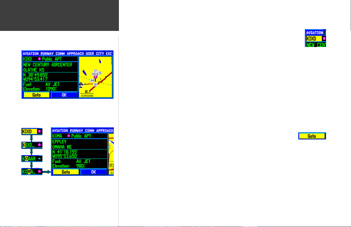
Features / Data Entry
Example of the on-screen cursor highlighting the ‘GOTO’
button. Use the ROCKER KEYPAD to move the cursor
around the page.
Example of the on-screen cursor during data entry. Data
entry begins and ends with the ENTER key. Use the UP/
DOWN portion of the ROCKER KEYPAD to select the
desired character and RIGHT to move to the next character.
The following features and data entry procedures are referred to throughout this manual.
CURSOR— A highlighted area on the screen (black text on yellow) which can be moved
up/down/left/right with the ROCKER KEYPAD to select individual fields on the display.
Moving the cursor to a given location allows you to begin data entry or scroll through a list.
FIELD— The location on a page (such as “waypoint name field”, shown at right) where a group of
characters or an option is entered and displayed. The cursor is placed on a field (using the ROCKER
KEYPAD) to begin data entry or selection of options.
To enter data in a data field:
1. Use the ROCKER KEYPAD to highlight the desired data field.
2. Press ENTER to begin data entry.
3. Use the ROCKER KEYPAD to enter the desired data. UP/DOWN to select the desired character and
RIGHT to move to the next character field. LEFT allows you to back up to the previous character
field or, when at the leftmost character field, to clear the entire data field.
4. Once the desired data has been entered, press ENTER to confirm.
ON-SCREEN BUTTON— Similar to “Field”. Place the cursor on a button and press ENTER to select
the action corresponding to that button. An example of an on-screen button is the
“GOTO” button appearing at the bottom of the waypoint information pages.
SCROLL BAR— When viewing a list of items too long to display on a single page, a scroll bar will
appear along the right-hand side of the list. The position of the scroll bar indicates which portion of the
list is currently being displayed. The height of the scroll bar indicates the number of items in the list.
To scroll through a list of items, use the UP/DOWN portion of the ROCKER KEYPAD.
DEFAULT— A system-selected format, built into the operating software or the unit’s memory, that will
be followed unless the user chooses a different setting. For example, the default setting for speed readings
is ‘knots’, but can be changed to ‘miles per hour’ or ‘kilometers per hour’. Once a setting is changed, the
new setting is retained until another change is made or a ‘Restore Defaults’ menu option is selected.
2

To turn the GPSMAP 295 on, press and hold the RED POWER KEY.
A Welcome Page will appear while the unit conducts a self test. Once testing is complete, the
Welcome Page is replaced by a Database Page. The Database Page shows the effective dates for the
Jeppesen database and a warning that the GPSMAP 295 is for VFR use only.
Press ENTER to acknowledge the Database Page.
The Satellite Status Page will appear as the GPSMAP 295 looks for available satellites. The
GPSMAP 295 continuously collects and stores “almanac” data when it receives a satellite(s). Almanac
data tells the GPS receiver where to look for each GPS satellite in the constellation. Each time you turn
the GPSMAP 295 on, it will use this almanac data—along with last known position, date and time—to
determine which satellites should be in view.
A minimum of three satellites is required for a two-dimensional position fix (2D Navigation),
whereas at least four satellites are necessary for a three-dimensional position (3D Navigation). A threedimensional position includes latitude, longitude and altitude. Additional satellites are occasionally
needed to triangulate your position and, even if not needed to determine a position, additional satellites
will also improve position accuracy.
During normal use, expect a position fix in 30-45 seconds. Once a sufficient number of satellites are
received, the GPSMAP 295 will automatically transition from the Satellite Status Page to the Map Page.
Your position will appear on the map and, once you select a destination, the GPSMAP 295 will be ready
to help you navigate.
Basic Operation
Turning the Unit On / Off
After the initial Welcome Page, the Database Page appears to
indicate the database coverage area and effective dates. A
warning also reminds you that electronic charts should always
be double-checked for accuracy and are for VFR use only.
F
If you press any keys while the unit is acquiring satellites, the automatic sequencing
from Satellite Status Page to Map Page will not occur.
At the end of the day, when you’re finished using the GPSMAP 295, the same RED POWER KEY
that you use to turn the unit on also turns the unit off.
To turn the GPSMAP 295 off, press and hold the RED POWER KEY.
An additional page will appear in the start up sequence
when an optional MetroGuide cartridge is installed.
MetroGuide cartridges provide additional map detail and
“points of interest” data for automotive use.
3

Basic Operation
Main Page Sequence
The GPSMAP 295 features five main pages which are linked together, in series. You can quickly
cycle through these main pages—in either direction—using the PAGE and QUIT keys. Each of these
main pages is described in greater detail on the following pages.
Satellite Status Page
PAGE
When the GPSMAP 295 is turned on and a position fix is
determined, the unit will automatically transition from the
Satellite Status Page to the Map Page (provided no keys
have been pressed after turning the unit on).
4
>>>
Position Page
Map Page
To display the next page in the sequence, press PAGE.
To display the previous page in the sequence, press QUIT.
As you become more familiar with the GPSMAP 295, you’ll find that using both PAGE and QUIT
allows you to quickly select the desired page. For example, to quickly jump from the Map Page to the
HSI Page, press PAGE. To return from the HSI Page to the Map Page, press QUIT. (You may find it
desirable to cycle between these two pages, however, the GPSMAP 295’s split screen capability allows
you to display the map and HSI on the same page!)
HSI Page
(RMI Page in Land Mode)
Active Route Page
>>>
QUIT

The GPSMAP 295’s backlighting illuminates the display and keypad for optimal visibility. There are
ten levels of screen backlighting, providing maximum flexibility. At night, you can easily turn the
backlighting level down to prevent unwanted glare and distraction.
Screen contrast is adjustable as well. You may find it necessary to adjust the contrast setting as the
ambient temperature changes.
Backlighting and screen contrast are adjusted using the RED POWER KEY and the ROCKER
KEYPAD. A pop-up window shows the current settings and the progress of any adjustments you
have made.
To adjust the screen backlighting and contrast:
1. From any page, press the RED POWER KEY momentarily. A pop-up window will appear showing
the current contrast and backlighting settings.
2. Press the UP/DOWN portion of the ROCKER KEYPAD to change the backlighting settings. UP will
increase backlight intensity; DOWN will decrease backlight intensity.
3. Press the LEFT/RIGHT portion of the ROCKER KEYPAD to adjust screen contrast. LEFT will make
screen contrast lighter; RIGHT will make screen contrast darker.
4. Press ENTER to accept any changes and remove the screen settings window. Alternatively, if no
keys are pressed, the screen settings window will automatically be removed after five seconds.
Basic Operation
Screen Backlighting / Contrast
A pop-up window appears when the RED POWER KEY is
pressed momentarily. Use the ROCKER KEYPAD to make
any desired screen adjustments: UP/DOWN for backlighting
level and LEFT/RIGHT for contrast setting.
F
On warmer days you may find it necessary to decrease the contrast setting for optimal
screen clarity. Conversely, on cold days it may be necessary to increase the contrast
setting to make screen information more legible.
5

Basic Operation
Aviation vs. Land Mode
Press MENU, with the Satellite Status Page displayed, to
show the page options. ‘Enter Land Mode’ or ‘Enter Aviation
Mode’ will appear (as appropriate)—allowing you to select
whichever mode is not currently being used.
The RMI Page replaces the HSI Page when Land Mode is
selected. The RMI Page depicts direction of travel (ground
track) on a rotating compass card, and bearing to
destination using a bearing pointer.
6
Your GPSMAP 295 is designed to be flexible. The unit provides “Land Mode” and “Aviation Mode”
settings, allowing you to tailor many features specifically for automotive or airborne use.
In Land Mode, some alert messages—which would be appropriate in the cockpit—are disabled to
prevent nuisance messages not needed while driving. Additionally, there are many settings on the
GPSMAP 295 you can make on your own. For example, speed can be displayed in knots, miles per
hour or kilometers per hour. The GPSMAP 295 provides the flexibility to have separate settings for
Aviation Mode and Land Mode (and saves them in memory so you do not have to re-enter them the
next time you switch between modes).
The chart below describes the differences between Aviation and Land Mode.
AVIATION MODE:
Uses Airplane Symbol on Map to indicate current position.
Airplane Symbol appears at GPS-determined position.
HSI Page is displayed for Navigation Guidance.
GOTO navigation is along Selected Course (determined when GOTO is initiated).
Independent (from Land Mode) user-defined settings for Distance, Speed, North reference (true or magnetic),
Arrival Alarm, Land Data (appearing on Map), Aviation Data (appearing on Map).
LAND MODE:
Uses Pointer Symbol on Map to indicate current position.
Pointer Symbol is aligned to the Nearest Road (where practical).
RMI Page is displayed for Navigation Guidance.
GOTO navigation is from Present Position (updates guidance information as you drive).
All Vertical Navigation (VNAV) messages, Airspace Alert messages and Course Deviation Alarm are disabled.
Independent (from Aviation Mode) user-defined settings for Distance, Speed, North reference (true or
magnetic), Arrival Alarm, Land Data (appearing on Map), Aviation Data (appearing on Map).

Receiver Status
Sky View
Estimated Position Error
Signal Strength Bars
Battery Level Indicator
The Satellite Status Page is the first of five main pages and provides a visual reference of receiver
functions, including current satellite coverage, receiver status, battery level and position accuracy. As the
receiver locks onto satellites, a signal strength bar will appear for each satellite in view, with the
appropriate satellite number (from 01-32) underneath each bar. The progress of satellite acquisition is
shown in three stages:
• No Signal Strength Bar— the receiver is looking for the satellite(s) indicated. The corresponding
number(s) on the sky view is not highlighted.
• Hollow Signal Strength Bar— the receiver has found the satellite and is collecting data.
• Solid Signal Strength Bar— the receiver has collected the necessary data and the satellite(s) is
ready for use. The corresponding number(s) on the sky view is highlighted.
Each satellite has a 30-second data transmission that must be collected (hollow signal strength bar,
as described above) before that satellite may be used for navigation (solid signal strength bar). Once a
fix has been calculated, the GPSMAP 295 will then update your position, ground track, and ground
speed by selecting and using the best satellites in view.
Sky View and Signal Strength Bars
The sky view and signal strength bars give you an indication of what satellites are currently visible,
which satellites are being used to calculate a position fix, and the signal quality. The sky view shows a
“bird’s eye” view of each satellite’s position relative to the unit’s last known position. The outer circle
represents the horizon in all directions (with cardinal heading references). The inner circle represents an
elevation of 45° above the horizon. Any satellite depicted near the center is directly overhead.
Main Pages
Satellite Status Page
The signal strength bars give you an indication of what
satellites are visible, whether they’re being used to calculate
a position fix, and the signal quality. A solid bar indicates a
satellite(s) ready to be used to determine a position fix.
The sky view graphically depicts where the visible satellites
are and which satellites are being received. The highlighted
satellite numbers indicate satellites currently being received.
7

Main Pages
Satellite Status Page
If satellite reception is lost, or an insufficient number of
satellites are available, you will be alerted with a ‘Poor
Coverage’ receiver status. This may be an indication of signal
interference or objects in the way of the receiver’s antenna.
When using the built-in simulator feature, the receiver status
will remind you of this setting by showing a ‘Simulating Nav’
status. Keep in mind the simulator feature should never be
used for actual navigation.
8
You can use the sky view to help determine if any satellites are being blocked, and whether you
have a current position fix (indicated by ‘2D Navigation’ or ‘3D Navigation’ in the status field). You can
also set the sky view to a ‘Track Up’ configuration (instead of ‘North Up’), causing the top of the sky
view to align to your current track heading.
Receiver Status
As soon as the GPSMAP 295 has collected the necessary data to calculate a fix, the status field will
indicate a 2D or 3D status. (For ‘2D’, you may need to enter your altitude. See page 12.) Receiver status
is indicated at the top left corner of the page. The status will be shown as one of the following conditions:
Searching— the GPSMAP 295 is looking for any available satellites in view.
AutoLocate— the GPSMAP 295 is initializing and collecting new almanac data. This process can
take up to five minutes, depending on the satellites currently in view.
Acquiring— the receiver is collecting data from available satellites, but has not collected enough
data to calculate a position fix.
2D Navigation— at least three satellites with good geometry have been locked onto and a two-
dimensional position fix (latitude and longitude) is being calculated. ‘2D Diff’ will appear when you
are receiving DGPS corrections with a two-dimensional position.
3D Navigation— at least four satellites with good geometry have been locked onto, and your
position is now being calculated in latitude, longitude and altitude. ‘3D Diff’ will appear when you
are receiving DGPS corrections with a three-dimensional position.
Poor GPS Coverage— the receiver isn’t tracking enough satellites for a 2D or 3D fix due to bad
satellite geometry.
Not Usable— the receiver is unusable, possibly due to incorrect initialization or abnormal satellite
conditions. Turn the unit off and back on to reset, and reinitialize the receiver if necessary.
Simulating Nav— the receiver is in simulator mode.
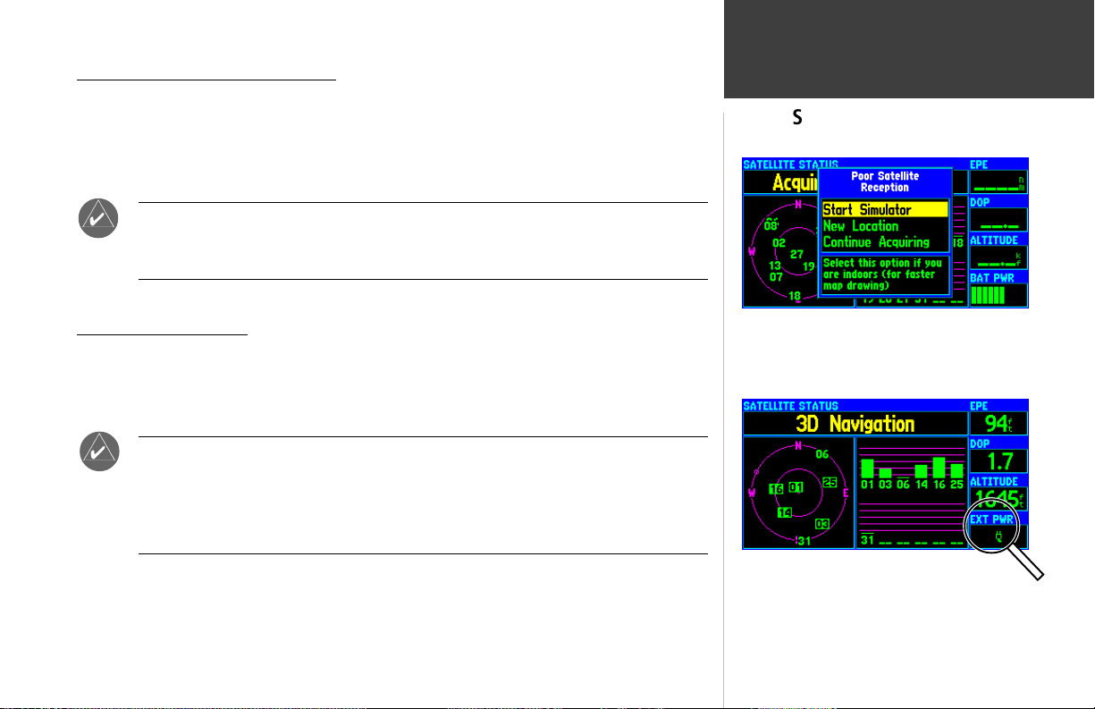
‘Poor Satellite Reception’ Window
If no satellites are received for several minutes (or an insufficient number of satellites are received to
determine a position fix) a message will appear, prompting you to update your approximate location or
start the built-in simulator. Updating your approximate location will ensure the GPSMAP 295 is searching for the correct satellites, and is useful if you have traveled over 500 miles with the unit turned off.
Main Pages
Satellite Status Page
F
Battery level Indicator
which displays the condition of the unit’s batteries. The battery indicator is replaced by an external
power icon when operating from an external power source (10-35 volts DC).
F
The ‘Poor Satellite Reception’ prompt may appear when you first use your
GPSMAP 295. The prompt may also appear during normal use if the antenna is
shaded (such as operation in an aircraft hangar) or when the unit is used indoors.
The Satellite Status Page also features a battery level indicator, located in the bottom right corner,
The battery level indicator is calibrated for alkaline batteries. NiCad batteries will
display the battery level differently due to voltage and discharge pattern differences.
To display the battery level accurately select the appropriate type, as described on page
76. When replacing the AA batteries, the GPSMAP 295’s internal memory will maintain
any settings, user-created waypoints and flight plans.
If satellites are NOT received after several minutes of
operation, the ‘Poor Satellite Reception’ window will appear.
Select ‘New Location’ to update your current position (from
last known) or ‘Continue Acquiring’ to keep searching.
When using external power, the on-screen battery level
indicator is replaced by an external power icon.
9

Main Pages
Satellite Status Page
Press MENU to display the Satellite Status Page Options.
Use the ROCKER KEYPAD to select the desired menu
option and press ENTER.
If the built-in simulator feature is currently active, ‘Stop
Simulator’ will appear as an option (replacing ‘Start
Simulator’).
10
EPE and DOP
The Satellite Status Page indicates the accuracy of the position fix, using Estimated Position Error
(EPE) and Dilution of Precision (DOP) figures. DOP measures satellite geometry quality (i.e., number
of satellites received and where they are relative to each other) on a scale from one to ten. The lowest
numbers are the best accuracy and the highest numbers are the worst. EPE uses DOP and other factors
to calculate a horizontal position error, in feet or meters.
Track Bug
When you are flying or driving, you may observe a small circle along the outer ring of the sky view.
This “track bug” indicates your current ground track and is helpful in determining location of satellites
relative to your current track. The track bug is not available when the sky view is set to a ‘Track Up’
orientation, as described on the following page.
Satellite Status Page Options
Many features of the GPSMAP 295 are menu driven. Each of the main pages has an options menu,
allowing you to custom tailor the corresponding page to your preferences and/or select special features
which specifically relate to that page.
To display the Satellite Status Page Options, press MENU (with the Satellite Status
Page displayed).
The following Satellite Status Page Options are available:
• Start Simulator • Enter Land Mode • Track Up
• AutoLocate • Initialize Position • Set Altitude
Start Simulator— allows you to activate the GPSMAP 295’s built-in simulator mode. If ‘Start
Simulator’ is selected, ‘Stop Simulator’ will appear as an option instead.
To activate (deactivate) simulator mode:
1. Use the ROCKER KEYPAD to highlight ‘Start Simulator’ (or ‘Stop Simulator’) and press ENTER.
2. Highlight ‘Yes’ and press ENTER.

Enter Land Mode— adapts GPSMAP 295 features for automotive use. The HSI Page is replaced
with an RMI Page, some aviation-related messages are disabled and some configuration settings
(such as units of measure for speed and distance) can be saved separately for Land Mode and
Aviation Mode. When Land Mode is selected, ‘Enter Aviation Mode’ will appear as an option instead.
See page 6 for more information about Land Mode and Aviation Mode.
To select Land Mode (or Aviation Mode) highlight ‘Enter Land Mode’ (or ‘Enter
Aviation Mode’) and press ENTER.
Track Up— changes the sky view display from ‘North Up’ orientation to align to current direction
of travel (ground track). If ‘Track Up’ is selected, ‘North Up’ will appear as an option instead.
To change the sky view orientation:
1. Use the ROCKER KEYPAD to highlight ‘Track Up’ (or ‘North Up’) and press ENTER.
AutoLocate— forces the GPSMAP 295 to search for any available satellite(s) to determine its
position.
This option is useful if you’ve relocated a long distance (greater than 500 miles) from the
last location the GPSMAP 295 was used. In such instances, without initialization, the GPSMAP 295
may otherwise be looking for the wrong group of satellites.
To select AutoLocate, highlight ‘AutoLocate’ and press ENTER.
Initialize Position— allows you to designate your approximate position in order to speed up
satellite acquisition. This option may be used in lieu of ‘AutoLocate’, above.
To initialize your starting position:
1. Use the ROCKER KEYPAD to highlight ‘Initialize Position’ and press ENTER.
2. Designate your approximate position on the map using the ROCKER KEYPAD and press ENTER.
(You may wish to use the IN and OUT zoom keys to adjust the level of detail displayed, as you
determine your approximate position.)
Main Pages
Satellite Status Page Options
Land Mode disables the airspace alert messages and replaces
the graphic HSI with an RMI. The RMI depicts ground track
and bearing to destination only. Select Land Mode when
using the GPSMAP 295 in an automobile.
Use the ‘Initialize Position’ option to speed up satellite
acquisition—especially if your have travelled a great
distance (> 500 miles) with the GPSMAP 295 turned off.
11

Main Pages
Satellite Status Page Options
The ‘Set Altitude’ option is only available (or needed) when
the GPSMAP 295 has a ‘2D Navigation’ position and
cannot determine altitude on its own. Providing an
approximate altitude will improve position accuracy.
Position Page with current position displayed in degrees/
minutes/seconds. The degrees/minutes format is shown in the
illustration at right. See page 77 for information on
changing the position format.
12
Set Altitude— allows you to designate your approximate altitude, when the GPSMAP 295 is
acquiring satellites or navigating in with a two-dimensional position. By default, 2D navigation will
attempt to use the last known altitude. If the altitude shown is off by several hundred feet (or more),
manually entering your approximate altitude will enable the receiver to more accurately determine a
position fix.
To enter an altitude:
1. Use the ROCKER KEYPAD to Highlight ‘Set Altitude’ and press ENTER.
2. Enter your approximate altitude using the ROCKER KEYPAD, and press ENTER.
Position Page
Track
Compass
Current Position
Coordinates
User-selectable
Data Fields
Current Time
and Date
The second main page is the Position Page, which shows where you are, what direction you are
heading, and how fast you are going. This page also provides several trip computer functions, such as
average speed, maximum speed, a trip timer and a trip odometer.
The graphic heading display at the top of the page indicates the direction you’re heading, or ground
track, only while you’re moving. Directly below the graphic heading display are present position and
time readouts. By default, your position is displayed using latitude and longitude, in degrees and
decimal minutes. Other position format options are available as described on page 77. The current time
is displayed in local or UTC (coordinated universal time or “zulu”). To switch between local and UTC
time displays see page 76.

Along the right-hand side of the page are eight user-selectable data fields which display the
following items by default: ground speed, ground track, average speed, maximum speed, trip odometer,
trip timer, and sunrise/sunset times for the current date & position. To select a different data item to
display on any data field see the options below or Appendix E for definitions of available data items.
Position Page Options
Many features of the GPSMAP 295 are menu driven. Each of the main pages has an options menu,
allowing you to custom tailor the corresponding page to your preferences and/or select features which
specifically relate to that page.
To display the Position Page Options, press MENU (with the Position Page displayed).
The following options are available:
• Change Fields • Reset Trip • Reset Max Speed
• Reset Odometer • Reset All • Restore Default
Change Fields—
allows you to choose the data types displayed on the eight user-selectable data
fields (along the right-hand side of the Position Page). Available data types are: Altitude, Odometer,
Speed, Maximum Speed (MAX SPD), Sunrise at present position, Sunset at present position, Track, Trip
Average Speed while moving (MOVE AVG), Trip Average Speed overall (AVG SPD), Trip Odometer
(TRIP ODOM), Trip Timer while moving (MOVE TMR), Trip Timer while stopped (STOP TMR), Trip
Timer total (TRIP TMR) and User Timer (USR TMR). See page 95 for descriptions of these terms.
To change a data field:
1. Use the ROCKER KEYPAD to highlight ‘Change Fields’ and press ENTER.
2. Highlight the data field you wish to change (using the ROCKER KEYPAD) and press ENTER.
3.
Use the ROCKER KEYPAD to select the type of data you want to appear on this field and press
ENTER.
Main Pages
Position Page
Select the ‘Change Fields’ option, then use the ROCKER
KEYPAD to select the data field you wish to change and
press ENTER...
...a list of available data type appears. Use the ROCKER
KEYPAD to select the desired data type and press ENTER.
13

Main Pages
Position Page Options
’Reset Trip’ clears the trip odometer, trip timers and trip
average speed readouts—but, leaves the maximum speed
and odometer information intact.
Use the ‘Reset All’ option to clear all trip computer readouts,
including maximum speed and the odometer.
Reset Trip— clears the trip odometer, trip timers and trip average speed readouts.
To reset the trip computer readouts, use the ROCKER KEYPAD to highlight ‘Reset
Trip’ and press ENTER.
Reset Max Speed— clears the maximum speed readout.
To reset the maximum speed readout, highlight ‘Reset Max Speed’ and press ENTER.
Reset Odometer— clears the odometer readout.
To reset the odometer readout, highlight ‘Reset Odometer’ and press ENTER.
Reset All— clears all trip computer, maximum speed and odometer readouts.
To reset all trip computer/maximum speed/odometer readouts, use the ROCKER
KEYPAD to highlight ‘Reset All’ and press ENTER.
Restore Default— resets all data fields to the factory default settings (as described on the
previous page).
To restore the factory default settings, use the ROCKER KEYPAD to highlight ‘Restore
Default’ and press ENTER.
14

Nearby
Navaid
(Intersection)
User-selectable
Data Fields
Main Pages
Map Page
Present
Position
Graphic HSI
The GPSMAP 295 features a real-time moving map (shown above in Night Color Mode) that can
do much more than just plot your course. The Map Page displays a digital map—including airspace
boundaries, airports, navaids, lakes, rivers, coastlines, cities and highways. An on-screen cursor lets you
pan ahead to other map areas, determine the distance and bearing to any map position, and perform
various waypoint and route functions. The GPSMAP 295 includes dedicated zoom keys for instant map
scale adjustments. The map portion of the page displays your present position using an aircraft icon (or
a pointer icon when using Land Mode), with your ground track and/or route displayed as small points
on the screen (an electronic bread crumb trail). You may select which features are shown on the Map
Page using the Map Page Options, as described on page 19.
By default, two user-selectable data fields appear in the upper right corner—displaying distance to
next destination waypoint and ground speed—along with a graphic HSI directly below the data fields.
From the Map Page Options, each data field may be configured to display any one of twenty-one data
options. You can also add more data fields along the right-hand side of the page, or select a full-screen
map, using the Map Page Options (see page 24).
The graphic HSI (horizontal situation indicator, see page 26) provides “at a glance” visual guidance
along your designated course. The course deviation needle will move left or right if you move off your
desired course and the desired course pointer will remind you of your intended course heading. Both
elements are superimposed on a rotating compass card, the top of which indicates current ground
track. The HSI is replaced by an RMI when using Land Mode (see page 31).
Use the IN and OUT Zoom keys to adjust the map scale.
Example above shown in Day Color Mode.
The RMI replaces the HSI when using Land Mode. The RMI
indicates bearing to destination (using a bearing pointer)
and ground track (using a rotating compass card).
15

Main Pages
Map Page
Zooming, Panning and Pointing
There are three main actions you can perform on the Map Page: zooming, panning, and pointing.
The map display has 24 map scales (from 120 feet to 800 miles) which are selected by pressing the IN
and OUT zoom keys. The current map scale is indicated in the bottom left corner of the map display.
To change the map scale:
1. Press the IN zoom key to see a smaller area with more detail.
2. Press the OUT zoom key to see a larger area with less detail.
At the lowest map scales, ‘overzoom’ appears directly below
the map scale. This indicates you have exceeded the
resolution of the background map. Exercise caution when
referencing ground features at these scale settings.
Use the ROCKER KEYPAD to pan the map. Note the
panning pointer which appears on the map. Bearing and
distance to the pointer, along with the pointers position
coordinates appears in a window at the top of the map.
16
F
provides a “look ahead” capability which is particularly useful with smaller map areas.
for the map. If you change the scale, the map is redrawn with the pointer at the center. When the
pointer is placed on an object, the name of that object will be highlighted. (If the name wasn’t originally
displayed, it will appear when the pointer is placed on the object.) This feature applies to airports,
navaids, user-created waypoints, roads, lakes, rivers—everything displayed on the map except route
lines and track log data.
F
When zoomed in to the smallest map areas, ‘overzoom’ appears directly below the map
scale. This indicates the current scale exceeds the optimum resolution of available map
detail. Extra caution should be used in ‘overzoom’ since some detail, such as roads, are
drawn using widely spaced points and the actual layout of these details may differ
from the map presentation.
Panning allows you to move the map in order to view areas beyond the current map area. This
To activate the pan function, use the ROCKER KEYPAD to move the map in any
direction, including diagonally.
As you begin to pan the map, a pointer will appear. This map pointer will serve as a target marker
While panning the map, press NRST to display a list of cities, highway exits and points
of interest nearest to the map pointer’s location. The list of nearest airports and navaids
is always relative to your present position, not the panning pointer. See page 59.

When a waypoint name is highlighted, you can review information about the waypoint, list
waypoint options, or execute a GOTO right from the Map Page.
To select an on-screen airport, navaid or user waypoint with the panning pointer:
1. Use the ROCKER KEYPAD to highlight the desired item.
2. To view database information for the selected item, press ENTER.
3. For airports, use the ROCKER KEYPAD to highlight the various file tabs across the top of the page.
This allows you to quickly review field elevation, runway layout, communication frequencies and
available approaches.
4.
To exit the information pages, verify that the on-screen ‘OK’ button is highlighted and press
ENTER.
To GOTO an on-screen airport, navaid or user-created waypoint:
1. Use the ROCKER KEYPAD to highlight the desired item and press D WPT.
2. Press ENTER.
The GOTO function can be used anywhere on the map. If nothing currently exists at the map
pointer position, a new waypoint (called ‘MAP’) will be created at the pointer’s location before the
GOTO is initiated. You can also create a waypoint on the Map Page without selecting it as a GOTO
destination.
To create a user waypoint from the Map Page:
1.
Use the ROCKER KEYPAD to point to the desired location on the map and press ENTER. A waypoint information page will appear, with an auto-assigned name (3-digit number) for the waypoint.
2. With the on-screen ‘OK’ button highlighted, press ENTER.
Once you are finished with the panning function, you can quickly remove the panning pointer and
re-center the map on your present position using the QUIT key.
To cancel the map panning function and re-center the map on your present position,
press the QUIT key.
Main Pages
Map Page
When an on-screen airport is selected, the airport identifier
appears in highlighted text. Press ENTER to review
database information for the airport...
...to return to the Map Page, highlight the on-screen ‘OK’
button and press ENTER. Once you’ve returned to the Map
Page, press QUIT to cancel the panning function.
17

Main Pages
Map Page
When the panning cursor is placed within the boundaries of
an airspace, the airspace name, airspace type and floor/
ceiling limits appear in a text window.
Press ENTER to declutter the map. There are three levels
of decluttering, indicated directly below the map scale
(‘CLEAR -1’ in this example).
18
Retrieving Airspace Information
Panning and pointing may also be used to retrieve information on airspaces depicted on the map.
Once the panning pointer is placed on an open area within an airspace, the entire airspace, or airspace
sector, is highlighted. A text box adjacent to the panning pointer will indicate the airspace type and
floor/ceiling limits. Additional information, including communication frequencies, is available from the
waypoint information pages.
To retrieve airspace information from the Map Page:
1. Use the ROCKER KEYPAD to select an open area within the desired airspace’s boundary. The
boundary line is highlighted and a window appears showing airspace type and floor/ceiling limits.
2. To display additional information, such as controlling agency, press ENTER. Communication
frequencies may then be displayed by highlighting the on-screen ‘Frequencies’ button and pressing
ENTER. Or, with the on-screen ‘OK’ button highlighted, press ENTER to return to the Map Page.
Easy Screen Decluttering
You can select the desired level of map detail using the ‘Setup Map’ option described on the
following page. You may, however, wish to temporarily remove some map detail in congested areas.
There are three declutter settings which will remove the background detail (lakes/rivers/highways),
airspace boundaries, and—at the highest declutter level—all map detail except those waypoints which
are part of your selected route. Map decluttering is selected with the ENTER key.
To quickly declutter the Map Page (Aviation Mode only):
1. Press ENTER.
the map display. This declutter setting is identified by ‘CLEAR -1’ appearing below the map scale.
2. Press ENTER again. All background and airspace boundary detail is removed from the map display.
‘CLEAR -2’ appears below the map scale.
3. Press ENTER again. Only the waypoints which are part of the current GOTO or route appear on the
map display. ‘CLEAR -3’ appears below the map scale.
4. Press ENTER again to return ALL detail to the map display.
Background detail—including highways, cities, rivers & smaller lakes—is removed from

Many features of the GPSMAP 295 are menu driven. Each of the main pages has an options menu,
allowing you to custom tailor the corresponding page to your preferences and/or select special features
which specifically relate to that page.
To display the Map Page Options, press MENU (with the Map Page displayed).
The following options are available:
• Setup Map • Change Fields • Full Screen Map
• 2 Big-Number Fields • 2 Fields with HSI • 4 Fields
• 8 Fields • Measure Distance • Restore Default
• Show Next Street (only available in Land Mode)
Main Pages
Map Page Options
Change Fields—
allows you to choose the data types displayed on the two, four or eight userselectable data fields along the right-hand side of the page. There are twenty-one available data types:
Altitude, Bearing, Course, Course to Steer (CTS), Cross-Track Error (XTK), Distance to final Destination
(DIS DEST), Distance to Next waypoint (DIS NEXT), ETA to final Destination (ETA DEST), ETA to
Next waypoint (ETA NEXT), ETE to final Destination (ETE DEST), ETE to Next waypoint (ETE NEXT),
Estimated Time to VNAV (ETV), Glide Ratio (GR), Glide Ratio to Target (GRT), Speed, Track, Turn
(direction and angle), User Timer (USR TMR), Vertical Speed to Target (VST), Destination Waypoint
name (WPT DEST), Next Waypoint name (WPT NEXT). See page 95 for descriptions of these terms.
To change a data field:
1. Use the ROCKER KEYPAD to highlight ‘Change Fields’ and press ENTER.
2. Highlight the data field you wish to change and press ENTER.
3.
Use the ROCKER KEYPAD to select the type of data you want to appear on this field and press
ENTER.
The Map Page Options let you configure the Map Page with
a full screen map, additional data fields or change the type
of data appearing on the data fields.
To change the type of data displayed, select the ‘Change
Fields’ option, use the ROCKER KEYPAD to select the field
you wish to change and press ENTER. A pop-up window
will show all available data types.
19
Main Pages
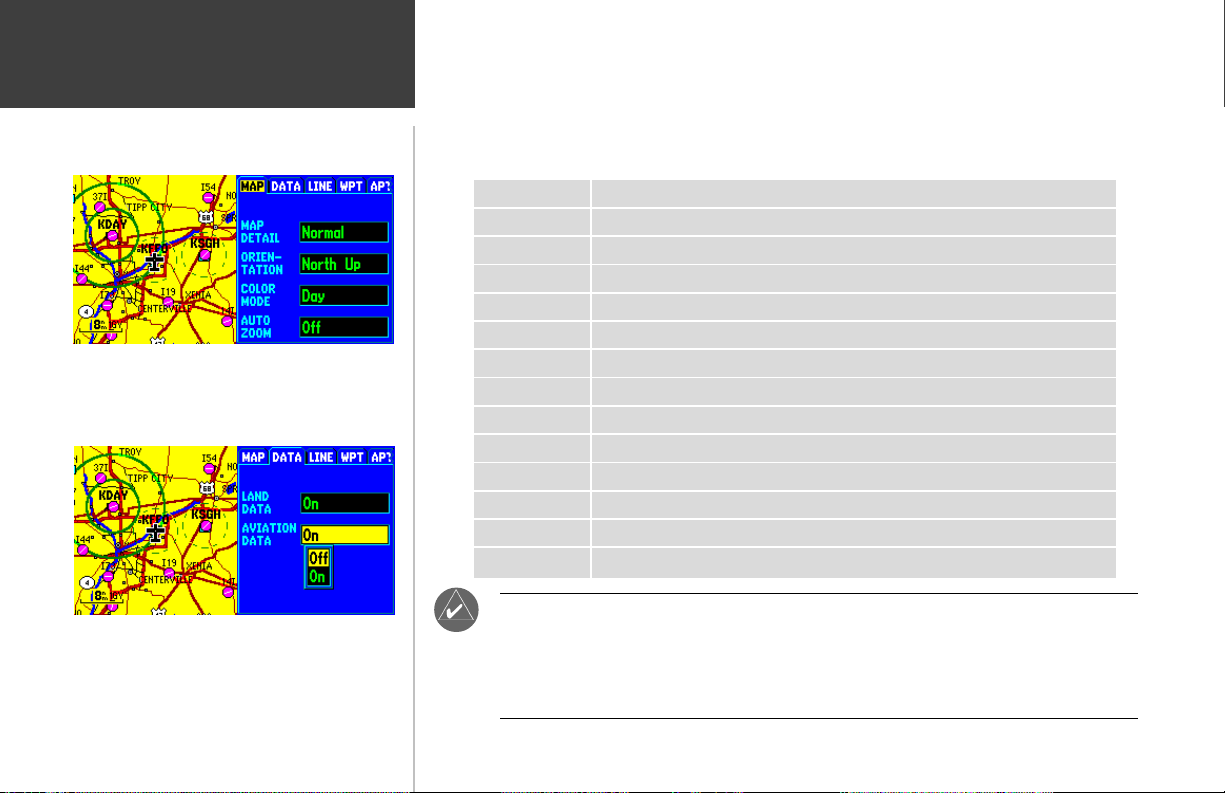
Map Page Options: Setup Map
’MAP’ is the first of 14 file tabs. The settings under this tab
allow you to adjust map detail (scale dependent); map
orientation (North Up, Track Up, etc.); Color Mode (Day or
Night); or AutoZoom.
Setup Map—
map orientation, automatic zooming, latitude/longitude grid, track and route lines, and waypoint
names. The map setup options are organized under a series of ‘file tabs’, making individual selections
easier to locate and change. The following table list the file tabs and settings available under each tab:
MAP Land Detail, Orientation, Color Mode, AutoZoom
DATA Land Data, Aviation Data
LINE Track Log, Active Route Lines, Railroads and Text, Lat/Lon Grid
WPT User-created Waypoints, Waypoint Text, Active Route Waypoints
APT Large/Medium/Small Airports and Text, Runway Labels
NAV VORs, NDBs, Intersections and Text
CTRL Controlled Airspace: Class B/C/D
SUA Special-use Airspace: Restricted, MOA, Mode C Veil, Other
CITY Large/Medium/Small Cities and Text; Small Towns
ROAD Freeway, National Highways, Local Highways, Local Roads, Road Names
POINT Geographic Landmarks, Marine Navaids, Highway Exits, Points of Interest
AREA Rivers/Lakes, Parks, Metro Areas, Other Areas, Descriptive Text
TOPO Major/Intermediate/Minor Contour Lines, Contour Text, Land Cover
MAPSOURCE Revision History, Map Name(s), Map Enable/Disable
allows you to configure the map display to your preferences, including map detail,
The ‘DATA’ file tab provides one-step ON/OFF selections for
land data and aviation data. When using the GPSMAP 295
in an automobile, you may wish to turn all the aviation
data—airports, navaids, airspaces—off.
20
F
Large airports are those with a runway longer than 8000’. Medium Airports are those
with a runway longer than 5000’ or with a control tower. Large cities are those with
approximate populations greater than 200,000 and medium cities are those with
approximate populations over 50,000. Small towns have approximate populations
under 5,000 or an unknown population size.
 Loading...