

Page 1
Apollo NMC
Navigation Management Computer
Operating Manual
July 1999 P/N 560-0164-01b
Page 2

NAVNETTMis a trademark of II Morrow Inc.
II Morrow
Apollo
TM
is a trademark of II Morrow Inc.
®
is a registered trademark of II Morrow Inc.
© 1999 by II Morrow Inc. All rights reserved.
Printed in the U.S.A.
II Morrow Inc./UPS Aviation Technologies, Inc.
Commercial Products Division
2345 Turner Road S.E.
Salem, OR 97302 U.S.A.
View our Web page: http://www.iimorrow.com or upsat.com
Email your comments about this manual to:
http://www.techpubs@at.ups.com
U.S.A. Toll-Free 800.742.0077
Canada Toll-Free 800.654.3415
International 503.391.3411
FAX 503.364.2138
Caution
The Apollo NMS (Navigation Management System) is a powerful
navigation tool, but you should never rely solely on any one piece of
navigation equipment. It’s important to maintain a constant awareness
of the navigation picture by using all appropriate resources.
Your new NMC and peripheral sensors should be installed only by an
FAA certified facility. Each installation is unique, and there are
several variables and cautions that an installer must deal with for you
to get the maximum benefit from your Apollo NMS.
Page 3

Important Notice
The Global Positioning System (GPS) is operated by the United States Department of Defense
which is solely responsible for the accuracy, daily operation, and maintenance of the satellite
constellation. System accuracy is affected by the Department of Defense’s Selective Availability
(SA) and the Dilution of Precision (DOP) attributed to poor satellite geometry.
Duetoimplementationof SelectiveAvailability bythe UnitedStates Departmentof Defense(DoD),
allGPS receiversmay sufferdegradation ofposition accuracy.The DoDhas stated that95% ofthe
timehorizontal accuracy willnot bedegraded morethan 100m and99.9% ofthe timeaccuracywill
not be degraded more than 300 m.
Installations of TSO C-129a authorized GPS Navigation Management Systems (NMS) may be
approved forsupplemental navigation only.The NMS maybe used asthe primary navigationdata
display, however, other means of navigation appropriate to the intended route of flight must be
installed and operational. It is not required that these other systems be monitored.
FCC Notice
This equipment has been tested and found to comply with the limits for a Class B digital device,
pursuant to part15of the FCC Rules. These limits aredesigned to provide reasonable protection
against harmful interference during residential use. Operation is subject to the following two
conditions:(1)this devicemay notcause harmful interference,and (2)this device mustaccept any
interference received,including interference that maycause undesired operation.This equipment
generates, uses and can radiate radio frequency energy and, if not installed and used in
accordance with the instructions, may cause harmful interference to radio communications.
However, there is no guarantee that interference will not occur in a particular installation. If this
equipment does cause harmful interference to radio or television reception, which can be
determined by turning the equipment off and on, the user is encouraged to try to correct the
interference by one or more of the following measures:
Reorient or relocate the receiving antenna.
·
Increase the separation between the equipment and receiver.
·
Connect the equipment into an outlet on a circuit different from that to which the
·
receiver is connected.
·
Consult the dealer or an experienced radio/TV technician for help.
Changesor modificationsto thisequipmentnot expresslyapproved byII MorrowInc.could voidthe
user’s authority to operate this equipment.
DOC Notice
This digital apparatus does not exceed the Class B limits for radio noise emissions from digital
apparatus as set out in the radio interference regulations of the Canadian Department of
Communications.
Le présent appareil numérique n’émet pas de bruits radioélectriques dépassant les limites
applicables aut appareils numérique de classe B prescrites dans le réglement sur le brouillage
radioélectrique édicté par le ministère des communications du canada.
i
Page 4

History of Revisions
Revision Date Software Ver. Manual P/N
April 1996 560-0164-00
December 1996 560-0164-00A
June 1997 560-0164-01
March 1998 6.1 560-0164-01A
July 1999 6.3 560-0164-01B
ii
Page 5

Conventions Used in This Manual
The Action (left) column depicts the steps involved in each procedure.
This column can beused byitself as a quick reference for pilotsalready
familiar with the system. The Explanation (right) column contains an
explanation of each step along with a sample of the NMS display you
will see while performing the procedure.
In this example the action is
“Press the SEL button and
turn the Small knob”
Action Explanation
2. Pressing SEL activates editing. The
SEL
Depicts the mode the
system is in
Preface
altimeter value flashes. Turn the small
knob to select the desired value.
ALTITUDE ASSIST
LOCAL ALTIMETER
SETTING 29.92
NAV
"·
Underlined characters
are flashing
Turn the small, inner
knob for more pages
when values are not
flashing
iii
Page 6

Conventions Used in This Manual (continued)
SEL Text in all caps and bold indicates the button to press.
NAV Normal text in all caps indicates an operation mode,
such
as Navigation mode.
“Airport” Text in quotes indicates information you will see on the
NMS display.
Large knob refers to turning the large, outer ring of the
two concentric knobs.
Small knob refers to turning the small, inner ring of the
two concentric knobs.
The button graphics refer to the buttons you should
SEL
press for the given examples.
NAV
press
for the examples.
Audience
This manual has been prepared with the following assumptions:
·
You are familiar with navigation instruments and displays
·
The approach and instrument navigation descriptions assume
you are familiar with instrument navigation charts and
procedures
Round button graphics refer to the mode buttons to
iv
Page 7

Apollo NMC
Welcome ...
Welcome to a new era of navigation. Once again, II Morrow Inc. has
set new standards in features and ease of use for the aviation industry.
The Apollo NMC is unequaled in providing the features, level of
performace, and reliability that aviation users require. The Apollo
NMC sets a precedent that will be the standard that all other navigation
instruments will be compared to.You canbe confident in knowing that
you are the owner of the state-of-the-art in navigation. Our products
are built to last and to allow for upgrading as your needs change in the
future.
It is important to note that only version 5.0, or later version, of the
Apollo NMC may be used for IFR GPS approach navigation. You can
determine your version by either the part number on the unit or in the
System Mode software version display.
Thank you again for choosing II Morrow to supply solutions to your
navigation needs.
Page 8

Apollo NMC
About This Manual
Please take a few moments to review the various sections of this
manual. Even if you are an experienced user of GPS navigation, be
sure to read the Basic Concepts and First Flight sections. These two
sections provide the rules for successful use of the Apollo NMC. The
rest of the manual contains important information that you can refer to
as you need more detail on specific procedures or features.
Page 9

Apollo NMC Table of Contents
Table of Contents
Caution .............................2
History of Revisions ......................ii
Preface .............................iii
Conventions Used in This Manual .............iii
Audience ..........................iv
Welcome ... .........................i
About This Manual .....................ii
Basic Concepts .........................1
Apollo Navigation Management System ..........1
Displays, Lights, and Controls ...............2
Power Switch ......................2
LED Display ......................2
Knobs ..........................2
Action Buttons .....................3
Mode Buttons ........................4
EMG (Emergency) Mode ................4
MSG (Message) Mode .................4
NAV (Navigation) Mode ................4
DB (Database) Mode ..................4
FPL (Flight Plan) Mode.................5
SYS (System) Mode ..................5
Features ...........................5
Operating Logic .......................7
First Flight ...........................9
Power-Up ..........................9
Direct Navigation ......................9
Navigation Displays ....................13
Power-Up Sequence......................15
EMG (Emergency) Mode...................25
EMG (Emergency) Mode Organization ..........26
Emergency Mode Displays ................27
v
Page 10

Table of Contents
Apollo NMC
EMG Mode Procedures....................30
Emergency Search/Direct-To Navigation . . . ......30
Searching Around a Waypoint...............33
Setting Runway Limits...................36
MSG (Message) Mode ....................39
Message Displays .....................40
Viewing Messages .....................41
Displaying SUA (Special Use Airspace) Information . . . 58
NAV (Navigation) Mode ...................61
NAV Displays .........................63
Top-Level Nav Displays ..................63
Navigation Sub-Displays .................68
Eight Character Nav Items.................70
Sixteen Character Nav Items................71
RAIM Predict Ignore List Sub-Displays..........77
Clear RAIM Predict Ignore List ..............77
NAV Mode Procedures ....................79
Displaying Nav Information ................79
Starting/Stopping Auto Nav Scroll ............79
Displaying Present Position ................80
Selecting a Position Sensor ................81
Automatic and Manual Position Sensor Selection.....82
Clear RAIM Predict Ignore List ..............86
Altitude Sensor Selection .................87
Setting the Altimeter (Barometric Pressure)........89
Setting/Editing Hold and Buffer Altitudes. . . ......90
Starting/Stopping Altitude Hold ..............91
Setting/Editing Auto Descent Values ...........93
Starting/Stopping Auto Descent ..............98
Parallel Course Offset ...................99
Activating/Deactivating/Editing Parallel Course Offset. . 99
Manual Air Speed ....................101
Countdown Timer ....................102
Setting/Starting the Countdown Timer ..........102
DME Arc Assist .....................103
vi
Page 11

Apollo NMC Table of Contents
Waypoint Distance Page .................103
Waypoint ETE Page ...................103
From-To-Next Waypoint ETA Page ...........104
Using the From/To/Next Nav Page............104
Inserting and Editing a From/To/Next Waypoint ....104
Hold/Continue the From/To/Next Sequencing ......106
DB (Database) Mode ....................107
Databases...........................109
Airport Database .....................109
VOR/NDB/Intersection
Databases .........................109
User Database ......................109
Database Information...................110
Airport Database ...................110
VOR/NDB/INT (Intersection) Databases ......111
User Database ....................111
Database Displays ....................112
DB Mode Procedures ....................115
Retrieving a Waypoint ..................115
Waypoint Retrieval by Identifier .............115
Retrieving a Waypoint by City/Facility Name ......118
Waypoint Information and Comments ..........121
Displaying Waypoint Information ............121
Entering/Editing Waypoint Comments..........122
Deleting a Waypoint Comment..............125
User Waypoints......................127
Creating a User Waypoint by Latitude/Longitude ....127
Creating a User Waypoint by Radial/Distance ......130
Editing a User Waypoint .................135
Deleting a User Waypoint ................139
FPL (Flight Plan) Mode ...................141
Flight Plan Summary Pages.................143
Creating a Flight Plan ..................144
Inserting and Editing Flight Plan Legs ..........145
Manually Selecting a Flight plan Leg ..........147
vii
Page 12

Table of Contents
Apollo NMC
Updating Leg Information ................148
Leg Information Options .................148
FUELAT.......................151
Using Flight Plan Comments ...............151
Accessing Flight Plan Summary Options ........153
Using Flight Plan Summary Options ...........154
Activate? .......................154
Load Approach ....................154
Cancel Oceanic....................158
Direct-To and the Active Flight Plan...........159
System (SYS) Mode .....................161
System Mode .......................162
SYS Mode Displays .....................163
Top-Level Displays....................163
Navigation Info Sub-State Displays ...........164
System Info Sub-State Displays .............167
Miscellaneous Sensors Sub-State Displays........174
Navigation Information Sub-State .............179
Airspace Alert Settings ..................181
Setting the Auto Nav Scroll Time ............185
Programmable and Autonav Nav Pages .........186
Restoring Default Nav Displays .............190
Manually Entering Magnetic Variation .........191
Changing the Oceanic Activation Altitude ........194
Editing the Flight Timer Trigger Speed .........195
Display Units .......................196
Description of the Direct-To Entry Option ........197
Editing the Direct-To Entry Option ...........198
CDI Scaling........................199
System Information Sub-State ...............201
Setting the Time and Date ................203
Choosing the Fuel Measure Units ............205
Choosing the Barometric Pressure Units .........206
Activating the Display Test................207
Displaying Software and Database Versions .......208
viii
Page 13

Apollo NMC Table of Contents
Entering and Editing Owner Information ........209
Position Sensor Sub-State ..................213
Loran Sensor Sub-State ...................214
Displaying Position Sensor Information .........214
Manual GRI Selection ..................215
Manual Triad Selection..................216
Miscellaneous Sensor Sub-State ..............219
Miscellaneous Sensor Sub-State .............219
Displaying Miscellaneous Sensor Information ......220
General Approach Overview ................221
Approach Topics .....................235
Manually Selecting a Flight plan Leg ..........236
Sequencing Details ....................239
Procedure Turns .....................241
Procedure Turn at an FAF ................242
Holding Patterns .....................246
DME-ARCs (Arc Assist) .................249
Other Uses for the Arc Assist Function .........253
Missed Approaches ....................254
GPS Approach Operations .................259
Operations ........................259
NMS Approach Procedure .................262
En route Operations ...................262
Approach Transition Operation (Enabling Approach) . . 264
Canceling An Approach .................271
Repeating an Approach..................272
Selecting a Different Approach..............273
Approach Examples .....................275
Introduction to Primary Oceanic/Remote Airspaces . . . 301
What is Primary Oceanic? ................301
Definitions ........................301
RAIM.............................305
What Is Raim? ......................305
How Is Raim Used? ...................305
ix
Page 14

Table of Contents
Apollo NMC
Approach Questions and Answers .............311
Troubleshooting .......................313
To Ensure Trouble Free Operation ............313
Battery Replacement ...................313
If You Have A Problem ..................313
If You Are Unable To Correct The Problem .......313
Contacting the Factory for Assistance ..........318
Glossary ...........................319
GPS Reference ........................327
General Information ...................327
Accuracy, Error, and Limitations.............328
Position Fix ........................330
Apollo NMC Flight Simulator ...............331
About the Flight Simulator ................331
NMC Removal (Panel Mount) ..............332
NMC Removal (Dzus Mount) ..............333
Connecting the Power Supply ..............334
Starting the Flight Simulation ..............335
Flight Simulator Operations ...............340
After the NMC is Re-Installed in the Aircraft ......340
Operating Manual Supplement
for the
Apollo 2002/2102 Keypad ...................1
History of Revisions.....................2
Ordering Information ....................2
Warranty Information ....................2
Using the Keypad ......................3
Waypoint Retriever Operation ...............4
x
Page 15
Apollo NMS
Basic Concepts
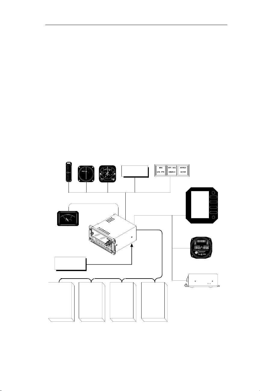
The Apollo NMS (Navigation Management System) uses a variety of
remote sensors to provide a broad range of information. The “heart” of
the system is the NMC (Nav Management Computer). The interface
network is called NAVNET
sensors to determine position, course, wind, altitude, and fuel
information. Some features require specific sensors. For example,
Altitude Assist features requires a Fuel/Air Data Sensor, or an altitude
encoder. Multiple position sensors and external
instruments/annunciators may be used for redundancy. The system
approach allows additional components to be added at any time.
Apollo Navigation Management System
TM
. The NMC interprets data from the
VDI*
VALID
DTRK
013TO
FMS1
00.00
FMS2
HDG
EFIS
Air Data
Computer**
Apollo
NMS
Keypad/
GPS
Sensor
2102*
CDI*
APR
ARINC 429/561
1NM
ILS1
TTG
MIN
Apo llo
NMS
MCLS
2010*
MSGVFR
PTK
I/O Devices
ARINC 429
HSI
NAV HDG
GS
GS
Autopilot
Apollo NMC*
Apollo
NMS
GPS
Sensor
2022*
NAVNET
Annunciators*
Serial Devices
NMS
Fuel/Air
Data
Sensor**
2030***
Shadin Digiflo / Miniflo
Fuel Flowmeters***
Apollo NMS Sensors
* Available from II Morrow Inc. or an authorized dealer
** Air Data Computer and Fuel/Air Data Sensors are mutually exclusive and
are shown together for illustration only.
*** Available from ShadinCo.
Moving Map
Altitude
Encoder***
1
Page 16
Apollo NMS
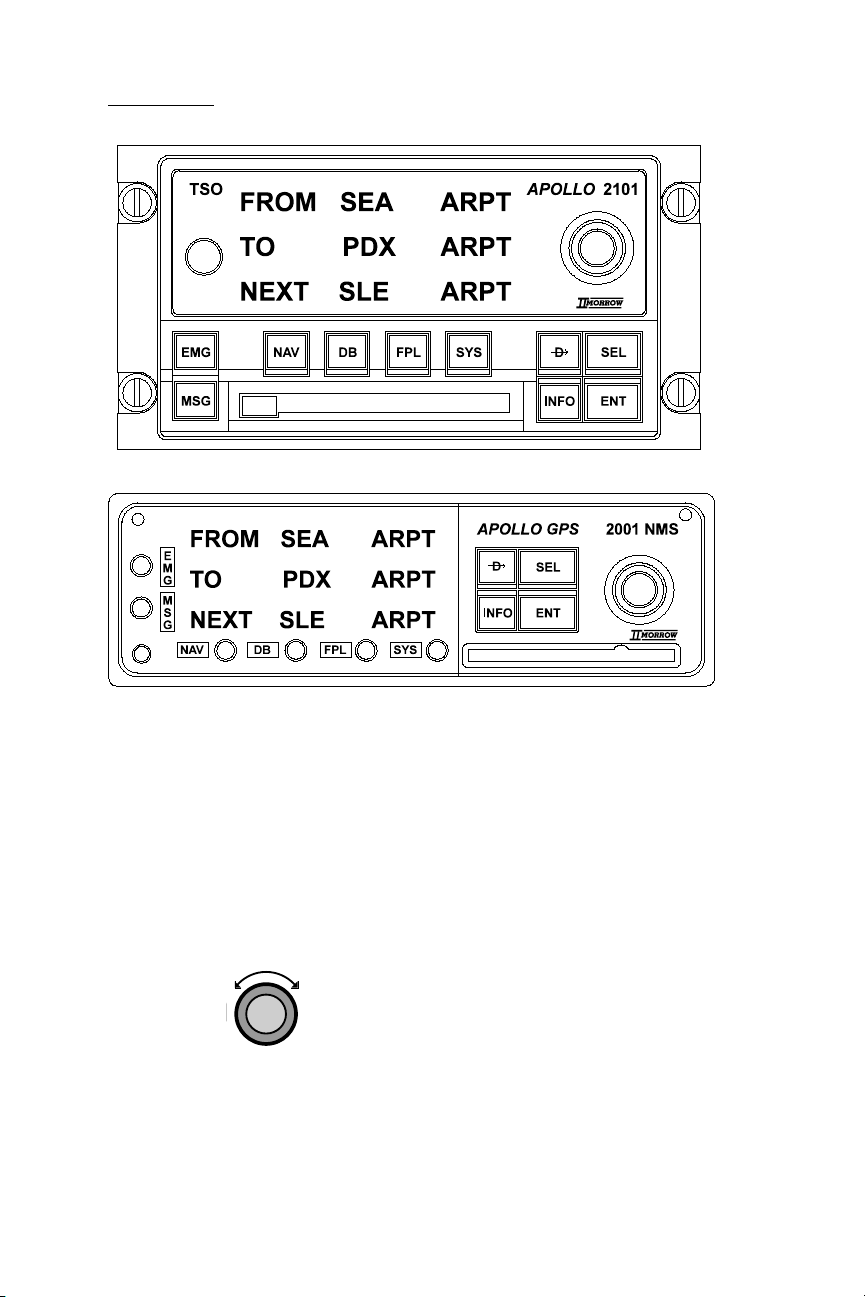
Displays, Lights, and Controls
Power Switch
A rotary switch is located on the front panel near the left side of the
2101 NMC. A pullswitch is located on theleft side of the 2001NMC.
LED Display
A photocell automatically adjusts the brightness of the LED (Light
Emitting Diode) display. The display consists of 3 lines with 16
characters each.
Knobs
The Large knob has two functions. First, it is used to scroll through
top-level displays in each mode. Second, when part of the display is
flashing (i.e., editing is on), the Large knob is used to choose which
character or characters on the display will flash.
2
Page 17

Apollo NMS
Displays, Lights, and Controls (continued)
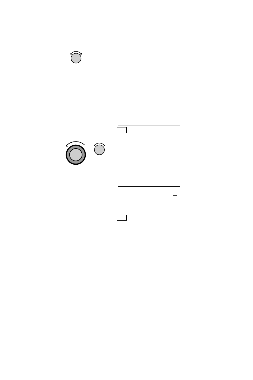
The Small, inner knob has two functions. First, it is used to
scroll through displays that pertain to the top-level displays;
that is, when the diamond
corner of a display. Second, when editing the display, a
character (or series of characters), will flash. The Small,
inner knob is then used to change the flashing character(s)
to the desired character(s).
Action Buttons
u appears in the lower right
SEL
INFO
ENT
D
(Select) The SEL button is used to activate editing. Editing
is active whenever part of the display is flashing. With some
features, editing is automatically activated without pressing
SEL.
(Information) The INFO button accesses supplementary
information about the displayed waypoint. It is also used to
access flight plan comments that you enter. Pressing this
button makes the current mode light flash, indicating you
are looking at waypoint or flight plan information. Pressing
this button again exits the INFO function.
(Enter) The ENT button enters and saves the information
flashing on the display. If ENT is not pressed, any changes
made are not saved.
(Direct-To) The DIRECT-TO button is used to define a
direct course from the present position to any waypoint. The
Waypoint Retriever, used to find waypoints in the database,
is automatically activated after pressing this button.
Pressing the DIRECT-TO button twice is used to enter a
desired course to or from the active waypoint. This action
automatically suspends waypoint sequencing.
3
Page 18

Apollo NMS
Mode Buttons
Pressing a Mode button places the NMC (Nav Management
Computer) into that mode. Each mode is used to perform certain types
of functions. The NMC is always in one of the six modes, signified by
the lighted mode annunciator.
EMG (Emergency) Mode
EMG
EMG mode is used to find the nearest waypoints and
nearest SUAs (Special Use Airspace areas) to your present
position, or to find the closest waypoints to a selected
waypoint. Search parameters, such as runway length, may
be set so the NMC (Nav Management Computer) only
displays airports and User waypoints that are suitable for
your aircraft.
MSG (Message) Mode
MSG
MSG mode is used to display messages. The NMC (Nav
Management Computer) alerts you to important conditions,
such as arrival at a waypoint, or degraded position accuracy.
The MSG light flashes when a new message condition
occurs, and is lit solid if any messages you have already
viewed remain.
NAV (Navigation) Mode
NAV
NAV mode is used to display navigation information, such
as the bearing, distance, and ETE (Estimated Time En
route) to the To waypoint. NAV mode may also provide
Altitude Assist features, Parallel Track, Current Position
Sensor information, a Countdown Timer, and From, To,
Next waypoint access.
DB (Database) Mode
DB
DB mode is used to access waypoints stored on a datacard,
and to create, store, and edit up to 200 User waypoints.
4
Page 19

Apollo NMS
Modes (continued)
FPL (Flight Plan) Mode
FPL
FPL mode is used to create, store, view, and edit up to 29
flight plans of up to 20 legs each and to edit the Active
flight plan. It can also provide advance information about
ETE, ETA, Fuel Usage, and other important flight statistics.
An approach is a set of waypoints inserted into the active
flight plan.
SYS (System) Mode
SYS
SYS mode is used to make certain settings and adjustments
to the system, such as adjusting the Time and Date, Fuel
Units, and Barometric Units. (Some settings, including
Time and Date, may also be adjusted during the start-up
sequence). SYS mode also provides status information for
position and other sensors.
Features
Below is a brief explanation of the features available with the Apollo
NMS.
Direct-To Flights: The NMS can provide course guidance from your
location directly to any waypoint in any database.
Data cards: Data cards contain listings of public use Airports, VORs,
NDBs, INTs (intersections), airspaces, non-precision approaches,
MSA, MESA, and magnetic variation information in the datacard
coverage area. The combined coverage area for all of the data cards is
world-wide.
Waypoint Information: Each database contains supplementary
information about every waypoint. For example, ATCfrequencies and
available runways may be displayed for airports. Approaches are also
stored on the data cards. In addition, bearing and distance from the
present position to any waypoint is also available.
5
Page 20

Apollo NMS
Features (continued)
Nearest Waypoint (Emergency) Search: The NMS finds the 20 nearest
waypoints of each type. The pilot can choose any of these waypoints and
set a course with the Direct-To feature. The NMC (Nav Management
Computer) can be set to display only those Airports and User waypoints
which meet your runway length and surface requirements. The NMC can
also search for the 20 nearest waypoints around any waypoint, not just
your present position.
Messages: The NMC (Nav Management Computer) automatically
alerts you of conditions which may require your attention, such as
nearing a Special Use airspace. Messages clear automatically, either
after they have been viewed, or when the condition clears.
Navigation Information: The NMC (Nav Management Computer)
constantly updates a wide variety of navigation information. With the
proper sensors installed, this information includes everything from true
airspeed to magnetic wind direction. Some information is available only
with a specific sensor installed.
Flight Plans: The NMC (Nav Management Computer) allows you to
store up to 30 flight plans of up to 20 legs each. These plans may be
viewed, activated, reversed, interrupted, edited, and deleted while en
route or on the ground. One of these flight plans is the Active flight
plan. From the first time a course is entered into the new unit, there is
always an Active flight plan. When any of the remaining 29 flight
plans is activated, the plan is copied over the current Active flight plan,
and the previous Active flight plan is deleted. Any changes to the
Active flight plan do not affect any of the other stored flight plans.
Approaches, when loaded, are placed at the end of the active flight
plan, replacing the destination airport.
System Customizing: The NMC (Nav Management Computer) uses
factory (default) settings that may be changed. For example, most of
the Nav displays may be changed to display the specific navigation
information you desire.
Additional Features: Certain additional features, such as Altitude
Assist, True Airspeed, and Outside Air Temperature, may be available
depending on what specific components are installed.
6
Page 21

Apollo NMS
Operating Logic
Use of the Waypoint Retriever is fundamental to operating the NMS.
The Waypoint Retriever is used to display specific waypoints, and is
discussed in detail in Operations, Retrieving a Waypoint.
The Waypoint Retriever is activated automatically when you are using
a feature that requires you to display a waypoint. For example, when
using the Direct-To feature, which allows you to navigate directly to
any waypoint in any database from your present position, pressing the
DIRECT-TO button activates the Waypoint Retriever. In effect,
pressing DIRECT-TO “tells” the system you want to navigate
directly to some specific location.
The system responds to your command by activating the Waypoint
Retriever. This is the system’s way of asking, “where do you want to
navigate to?” A display, similar to the one below, appears. In this
manual, black characters, such as the “A” in the display below,
indicate the item is flashing, and editing is activated.
AIRPORT AAP
HOUSTON
CITY TX USA
Whenever something on the display is flashing, it may be changed by
turning the Small knob. To make something else on the display flash,
turn the Large knob. The display shows the waypoint identifier and
the database containing the waypoint. In this example, the waypoint
AAP, located in the city Houston, Texas USA, is an Airport— i.e. is
contained in the Airport database. If the location you want to fly to is
also an airport, it is not necessary for you to change the waypoint type;
simply turn the Small knob to display first character in the waypoint
identifier, then turn the Large knob one increment clockwise to make
the next character flash. Use the knobs to choose the remaining
characters in the identifier, until the desired waypoint is displayed.
AIRPORT CBK
COLBY
CITY KS USA
7
Page 22

Apollo NMS
Operating Logic (continued)
If you wanted to fly to a different waypoint type, such as a VOR, you
would begin by changing the type. Turn the Large knob until the
waypoint type flashes.
AIRPORT AAP
HOUSTON
CITY TX USA
Select a different waypoint type by turning the Small knob.
VOR ABA
ARUBA
FACIL ANTILL
Turning the Large knob counter-clockwise causes the identifier to
again flash.
VOR ABA
ARUBA
FACIL ANTILL
Use the knobs tochoose theremaining characters in the identifier,until
the desired waypoint is displayed.
VOR CCR
CONCORD
FACIL CA USA
The last step isto pressthe ENT button. As faras the system memory is
concerned, nothing has changed until ENT is pressed. If you did not
want to navigate to the displayed waypoint, you would simply press
any mode button. Any time you want to abort a procedure, simply
press a mode button.
The Waypoint Retriever can also be used to look up waypoints using
the city or facility name. Refer to Database Mode, Retrieving a
Waypoint for full details.
8
Page 23

Apollo NMS
First Flight
WARNING
Before routinely using the Apollo NMS (Nav Management
System) in the air, you should be quite familiar with its
operation. Federal Aviation Regulations require pilots to
practice SEE AND AVOID. It is therefore critical you do
NOT study this manual while flying. It is recommended
your first flight be made during good weather in a low
traffic area.It is important you understand at least the First
Flight section before you fly. You may wish to practice at
home with the built-in simulator.
Power-Up
After the Nav Management Computer (NMC) is switched on, it
initializes its internal circuits. During this approximately 2 second
period, the display will remain blank. Following initialization, a
power-up sequence begins. After the sequence, the display below
appears. If the NMC (Nav Management Computer) has been removed
from the panel and used in simulator mode or the unit has moved
several hundred mile since the last time it was powered up, your
present position must be entered during the power-up sequence. See
Operations, Power-Up Sequence.
ETE --- --:--
--NAV FLAGGED-BRG --- --.NM·
NAV
Direct Navigation
This procedure is used to navigate from your present position directly
to any waypoint stored in a database. The waypoint you are flying to is
called the To waypoint.You willuse the Waypoint Retriever todisplay
the desired waypoint. The logic used is to:
·
Press the DIRECT-TO button. This activates the Waypoint
Retriever.
·
Select the TO waypoint using the SEL button and the Large
and Small knobs.
·
Press ENT.
9
Page 24

Apollo NMS
Direct Navigation
Action Explanation
1. The unit is in NAV mode, and the
Underlined characters
are flashing
The system is in NAV
(Navigation) mode
D
Waypoint Retriever is activated. The
waypoint identifier is flashing.
AIRPORT AAF
APALACHICOLA
CITY FL USA
NAV
2. When an item is flashing, turning the
Small knob displays other available
items. Turn the Small knob to choose
the desired waypoint type. In this
example, the VOR type is chosen.
VOR AAF
NABB
facil IN USA
NAV
3. Turning the Large knob causes
different items on the display to flash.
Turn the Large knob to make the first
character in the waypoint ident flash.
10
AIRPORT AAF
APALACHICOLA
city FL USA
NAV
Page 25
Apollo NMS [<*Heading_2]
Direct Navigation (continued)
4. Turn the Small knob to choose the
desired character. The remaining
identifier characters may change as the
knob is turned because the NMC (Nav
Management Computer) will not
display an identifier that doesn’t exist.
VOR DAG
DAGGETT
facil CA USA
NAV
5. Turn the Large and Small knobs to
choose the remaining characters in the
waypoint identifier. The desired
waypoint is displayed.
VOR DLS
THE DALLES
facil OR USA
NAV
11
Page 26

[<*Heading_2] Apollo NMS
Direct Navigation (continued)
7. Press ENT to select the waypoint as the
TO waypoint. The MNC will now
provice guidance on a course from your
ENT
ETE DLS 00:00
BRG159 82.7NM·
NAV
Indicates additional displays
(sub-pages) may be viewed by
turning the Small knob.
present position to the chosen
waypoint. Navigation information is
only displayed when position sensors
have completed acquiring signals.
à 0.00
12
Page 27

Apollo NMS [<*Heading_2]
Navigation Displays
The Small knob is used to scroll through the various navigation
displays. The diamond (
are sub-pages which may be viewed by turning the Small knob. In this
example, the sub-pages are additional navigation displays.
A brief explanation of these displays appears below. For more detailed
information, see the Operations section, Navigation Sub-Displays.
NAV FLAGGED appears on the middle line, and values for bearing
(BRG) and distance (NM) arezero untilthe system calculates position,
which takes from one to four minutes after power-up, and a To
waypoint is entered.
u ) in the lower-right corner indicates there
ETE DLS 00:31
à 0.26
BRG 165 45.6NM·
ETE DLS 00:31
à 0.26
DTK 167 72.5nm
ETE DLS 00:31
à 0.26
TRK 164 TAE 003
TOP LINE: The Estimated Time
En route (ETE) to DLS is 31
minutes.
MIDDLE LINE: The CDI indicator
(similar to a VOR CDI); The
desired course is towards the bar.
The selected course is 0.26nm to
the left.
BOTTOM LINE: The bearing to
DLS is 165º; the distance is
82.7nm.
ETE
CDI
The Desired Magnetic Track from
the From waypoint to DLS is 167°.
The distance between the FROM
and TO waypoints is 82.7nm.
ETE
CDI
The Magnetic Track is 164°; the
Track Angle Error is 3°.
13
Page 28

[<*Heading_2] Apollo NMS
Navigation Displays (continued)
ETE DLS 00:31
à 0.26
FT 00:12 163KTS
ETE DLS 00:31
à 0.26
TRK 164 165
ETE DLS 00:31
à 0.26
TRK 164 165
ETA DLS 14:56
MIN SAFEA 5700’
ENRTSAFEA 13600’
ETE
CDI
Flight time since departure is 12
minutes; the ground speed is 163
knots.
ETE
CDI
The track and bearing indicator.
The track is 164°; the current
bearing to DLS is 165°. The
bearing is displayed to the left or
the right side depending on
whether the aircraft is to the left or
right of the desired course. In this
example, the aircraft is to the right
of the desired course.
ETE
CDI
The current UTC (Coordinated
Universal Time) is 14:25 (2:25
pm).
Estimated Time of Arrival (ETA) at
DLS is 14:56 UTC.
MSA (Minimum Safe Altitude)
MESA (Minimum En route Safe
Altitude)
BARO ALT 390FT
----’ ABOVE HOLD
--:-- TO DESCENT
Barometric (Current) Altitude.
The distance (in feet) above or
below Hold altitude.
Time to beginning of Auto
descent. When Auto Descent has
started, this line displays the
distance (in feet) you are above or
below the glide path.
If the Fuel/Air Data Sensor is installed on the NMS, three additional
pages of navigation information will be available when you turn the
Small knob. See Nav Mode: Navigation Sub-Displays for more
information.
14
Page 29

Operations Power-Up Sequence
Power-Up Sequence
The power-up sequence is displayed every time the Apollo NMS is
turned on. The power-up sequence begins after the NMC completes an
approximately 2 second initialization of internal circuits. Following
initialization, the sequence will show the owner’s name, the database
version, the software version, present position, request for altimeter
correction factor, and the time/date. It also allows entry of a new
time/date and position during the sequence. The NMC will
automatically update the time from GPS satellite information at
power-up. If a valid datacard is not inserted, you will manually enter
the magnetic variation during the power-up sequence for the area you
will be flying in.In addition,the NMC displays start-up self-testpages,
self-test results, and asks if you want to continue with the last used
flight plan.
To acquire a position the systemmust “know” its approximate location
and, if using aGPS sensor, the time (UTCCoordinated Universal Time
formerly called Greenwich Mean Time).
Hint
The UTC and approximate positionshould beentered
by the installer; in which case, no action is normally
required of you during the power-up sequence. As
long as the system is functioning when you fly, the
NMS will always “know” its position the next time it
is powered up; however, if the NMC has been
removed from the panel for use in simulator mode,
your present position must be entered during
power-up after the unit is reinstalled in the aircraft.
Switching the power on starts the
POWER
power-up sequence.
APOLLO NMC
BY II MORROW
NAV
15
Page 30

Power-Up Sequence Operations
Power-Up Sequence (continued)
The Self-Test introductory page is displayed for 2 seconds.
STARTING
MEMORY
TESTS ...
NAV
The next self-test checks all of the NMC software, and takes about 4
seconds. During this time, the screen shown below is displayed.
Software Test
In Progress
Please Wait
NAV
The next self-test checks the User Waypoint database. If any errors are
found, the affected User Waypoints are cleared from memory, and the
display shown below is displayed until the user presses ENT.Ifno
errors are found, this page is not shown.
User DATABASE
Memory Failure
Press ENT
NAV
Next, all Flight Plan information is checked. If any errors are found,
the affected flight plans are cleared from memory, and the display
shown below is displayed until the user presses ENT. This page is not
shown if no flight plan errors are detected.
Flight Plan
Memory Failure
Press ENT
NAV
16
Page 31

Operations Power-Up Sequence
Power-Up Sequence (continued)
Remaining user-set-ups are tested next, resulting in the following
message if errors are detected. Again, this message is not shown in the
normal case where no errors are detected.
Memory Test
Failure
Press ENT
NAV
When the test is completed successfully, the following screen is
displayed for 2 seconds.
Software Test
Passed
NAV
Failure to pass the software test indicates a critical system error may
exist. In this case, the following message is displayed and the NMC
will not continue to function. If this problem should occur, return the
NMC to the dealer for repairs.
Software Test
Failed
Contact Dealer
NAV
If a datacard is in the datacard slot, it is tested next. This test checks all
of the datacard memory, taking about 5 seconds to complete. The test
is accompanied by the display shown below.
DATACARD TEST
In Progress
Please Wait...
NAV
When the test is completed successfully, the following screen is
displayed for 2 seconds.
17
Page 32

Power-Up Sequence Operations
Power-Up Sequence (continued)
Datacard Test
passed
NAV
Failure to pass the datacard check causes the display to show the next
page. The user must then press ENT to continue.
Datacard Failed
Contact IIMorrow
Press ENT
NAV
The Owner Name page is displayed for 2 seconds. The procedure for
entering owner information is described in Operations, Entering and
Editing Owner Information on page 209.
Property Of:
ORVILLE WRIGHT
KITTY HAWK
NAV
When a valid datacard is properly inserted in the datacard slot, the
database name, expiration date, and version number is displayed for 4
seconds.
West North Am Db
Date: 3/30/99
Version: 1.11
NAV
The display below onlyappears if the datacard is invalidor not inserted
properly. The magnetic variation value (in bold) is flashing. Rotate the
Small and Large knobs to update the magnetic variation for your
current position, then press ENT to save the displayed value.
18
Page 33

Operations Power-Up Sequence
Power-Up Sequence (continued)
No Database
Enter Manual
Mag Var: 00°W
NAV
If the Special Use Airspace (SUA) alerts have been turned off (see
System Mode for more information on SUA setups), the next screen is
displayed for up to 4 seconds.
Airspace Alert
Are Off
SEL To Reset
NAV
To turn the airspace alerts back on, press SEL when the screen shown
on the previous page is displayed, then press ENT when the screen
shown below appears, or press SEL to cancel.
Press ENT To
Turn Airspace
Alerts On
NAV
If the Special Use Airspace (SUA) setups (restricting which SUA
alerts are displayed) have been changed from the standard setups, the
screen shown below will be displayed for up to 4 seconds.
Airspace Setups
Are Non Standard
Setups
NAV
To reset the airspace setups, press SEL within 4 seconds, then press
ENT, as shown on the screen below, or press SEL again to cancel.
19
Page 34

Power-Up Sequence Operations
Power-Up Sequence (continued)
Press ENT To
Reset Airspace
Setups
NAV
If Emergency Search settings restricting runway lengths and/or
surface types and/or lighting requirements are entered, the display
below appears for up to 4 seconds.
Emergency Search
Is Non Standard
SEL To Reset
NAV
To reset the Emergency Search settings, press SEL within 4 seconds,
then press ENT, asshown on the screen below,or press SEL to cancel.
Press ENT To
Reset Emergency
Search Setups
NAV
If the 2030 Fuel/Air Data Sensor is installed, the NMC displays the
next screen until SEL is pressed.
FUEL ON BOARD
Must Be Verified
Press SEL
NAV
Enter the total amount of fuel which is in the airplane’s tanks including
reserve, by rotating the Small and Large knobs to edit the displayed
values, then press ENT. If the cursor is flashing on the word “FULL”
when ENT is pressed, the amount of fuel displayed will become the
maximum amount of fuel previously entered, and the cursor will flash
on the number. Pressing ENT again will enter the number as the
current total fuel on board.
20
Page 35

Operations Power-Up Sequence
Power-Up Sequence (continued)
If the total fuel entered is greater than previous Full tanks amount, the
Full tanks amount is updated to the newly entered value.
The total fuel entered is critical for accurate information to be
displayed in the Nav items which depend on F/ADS fuel tank
information.
Enter Total Fuel
On Board
Full or 00100usg
NAV
The Coordinated Universal Time (UTC - formerly called Greenwich
Mean Time) and date is displayed for up to 4 seconds.
The UTC may be reset hereby pressing SEL within 4 seconds,rotating
the Large and Small knobs, and pressing ENT to save the displayed
values. The UTC may also be reset in System Mode.
If using a GPS sensor, the UTC and date must be accurate for the
sensor to initialize in less than 30 minutes.
Date: 11 APR 99
Time: 15:14UTC
SEL To Reset
NAV
The display below, showing the present position in relation to the
nearest airport, appears for up to 10 seconds only if a valid datacard is
properly installed and the current position is within 600 nautical miles
of an airport in the database. Press SEL if the current position needs
updating.
Ppos: 0.0nm 000°
To Nrst Wpt PDX
SEL To Reset
NAV
21
Page 36

Power-Up Sequence Operations
Power-Up Sequence (continued)
If a valid datacard is not installed or the current position is nowhere
near an airport in the database,the display below appears instead forup
to 10 seconds. Again, press SEL to update the current position.
Ppos: 38°04.20N
102°41.28W
SEL To Reset
NAV
The displayed position is the location of the aircraft when the power
was last turned off; therefore, this position will not normally need to be
edited; however, in order for GPS sensors to initialize, and loran
sensors to select a GRI, the system must “know” its approximate
location.
If the NMC has been removed from the panel for use in Flight
Simulator mode, the display below appears after reinstallation in the
aircraft, and you must enter a reference position before the power-up
sequence will continue. Press SEL to update the current position.
Reset
Present Position
Press SEL
NAV
Rotate the Large and Small knobs to edit the values shown below.
Press ENT when the desired position is entered. Resetting the Present
Position (PPos) may be done by updating the latitude and longitude
directly, as shown below, or by choosing a reference waypoint as the
current position.
Ppos: 38°04.20N
102°41.28W
Ref Wpt: -----
NAV
22
Page 37

Operations Power-Up Sequence
Power-Up Sequence (continued)
In most cases, updating the present position may be simplified by
selecting a Reference Waypoint’s position, if the Reference Waypoint
is close to the current position. To do this, press ENT when the cursor
is flashing on the Reference Waypoint field, as shown below.
Ppos: 38°04.20N
102°41.28W
Ref Wpt: CHG?
NAV
The Waypoint Retriever will be started if ENT is pressed when the
cursor is flashing on “CHG?”, the Reference Waypoint Change field.
Refer to the Operating Logic section of Basic Concepts for detailed
information on the Waypoint Retriever.
When the desired waypoint has been found using the Waypoint
Retriever, press ENT to exit the Waypoint Retriever and to display the
current position of the retrieved waypoint. If you are satisfied with the
present position displayed, press ENT again to save it as the NMC’s
current position.
The final power-up screen, shown below, prompts you to enter a local
altimeter setting. This screen is only shown if an Altitude Encoder or a
Fuel/Air Data Sensor is installed. Turn the Small knob until the setting
is correct, then press ENT.
Altitude Assist
Local Altimeter
Setting 29.92"
NAV
ETE --- --:--
--Nav Flagged-brg --- -- nm·
NAV
23
Page 38

Power-Up Sequence Operations
Power-Up Sequence (continued)
At the end of the power up sequence, you need to decide if you want to
clear the last flight plan from memory. Turn the Small, inner knob to
display “YES” or “NO.” Then, press ENT.
CLEAR ACTIVE
FLIGHT PLAN
YES?
NAV
At this point, the power-up sequence is complete.
North America
EXPIRES 11/09/95
PRESS ENT
NAV
If your unit is installed for IFR GPS approach navigation, a sequence
of IFR output tests will be run to verify CDI andVDI annunciators as
well as a display test.
24
STARTING IFR
OUTPUT TESTS
NAV
Page 39

Operations Emergency Mode Displays
EMG (Emergency) Mode
Emergency mode helps you locate nearby waypoints quickly. In
addition to being useful in an emergency, this mode provides a quick
method of locating nearby waypoints in case of a diversion by ATC.
The databases included in the search are Airport, VOR, NDB, INT
(Intersection), and User. Emergency Search finds the 20 nearest
waypoints in each database. The feature also locates the 20 nearest
SUAs (Special Use Airspaces).
The Search Around a Waypoint feature is included in EMG mode, and
is very useful in flight planning. It displays the nearest waypoints and
SUAs relative to any waypoint in any database.
Runway limits can be used to display only those waypoints with
adequate landing facilities. Surface parameters can be Hard,
Hard/Soft, or Hard/Soft/Water. Runway length can range from 0 to
9900 feet in 100 foot increments. Lighting can be set to “YES”, or
“NO”.
25
Page 40

Emergency Mode Displays Operations
EMG (Emergency) Mode Organization
The figure below illustrates the organization of (EMG) Emergency
mode.
CHOOSE
SEARCH
WAYPOINT
RUNWAY
LIMITS
1
NEAREST
SUA
HOME PAGE
1
NEAREST
Airport
1
NEAREST
VOR
WAYPOINT
ENT ENT
RETRIEVER
2
NEAREST
SUA
2
NEAREST
Airport
2
NEAREST
VOR
3
NEAREST
SUA
NEAREST
Airport
3
NEAREST
VOR
1
NEAREST
Airport
3
NEAREST
Airport
20
NEAREST
SUA
20
NEAREST
Airport
20
NEAREST
VOR
20
26
1
NEAREST
NDB
1
NEAREST
INT
NEAREST
USER
2
NEAREST
NDB
2
NEAREST
INT
1
2
NEAREST
USER
3
NEAREST
NDB
3
NEAREST
INT
3
NEAREST
USER
20
NEAREST
NDB
20
NEAREST
INT
NEAREST
USER
20
Page 41

Operations Emergency Mode Displays
Emergency Mode Displays
The following are examplesof Emergency Mode displays. Thedisplay
below shows the second nearest airport to your present position
(PPOS). The waypoint identifier is shown in place of the PPos if you
are searching around a waypoint other than your present position. The
“2” on the top line indicates this is the second closest airport. The
second line shows the waypoint identifier, and the database. The
bottom line shows the bearing, relative bearing, and distance. The
relative bearing arrow shows the approximate direction relative to the
current ground track. In the example, the second closest airport to your
present position is SLE. The bearing to SLE is 75
is straight ahead, and the distance is 7.3 nm.
NEAR 2 TO PPOS
SLE AIRPORT
BRG 075°¾ 7.3NM
Turning the Large knob changes the database type. Below is an
example of a display showing the closest waypoint in the VOR
database.
o
, the relative bearing
NEAR 1 TO PPOS
CVO VOR
BRG 189°² 27.6NM
27
Page 42

Emergency Mode Displays Operations
Emergency Mode Displays (continued)
Turning the Small knob clockwise displays all the nearest waypoints
in the database in sequence. Below is an example of the 5th closest
VOR.
NEAR 5 TO PPOS
BTG VOR
BRG 006° 61NM
The display below may be selected with the Large knob after entering
EMG mode, and is used to display the nearest SUAs (Special Use
Airspace areas). The top line shows the name of the SUA. The “2”
indicates this is the 2nd closest SUA to your position. The middle line
shows the type of SUA. “Inside” means you are inside of the SUA. The
bearing and distance to the nearest edge of the airspace is shown on the
bottom line. In this example, the second closest SUA to your position
is the Portland Oregon ARSA, and the nearest edge of the ARSA is
o
005
, and 6.2 nm.
PORTLAND OR 2
ARSA INSIDE
BRG 005° 6.2NM
The display below may be selected with the Large knob after entering
EMG mode, and is used to search around a waypoint. Pressing ENT
activates the Waypoint Retriever, allowing you to specify which
waypoint you want the system to search around.
CHOOSE WPT TO
SEARCH AROUND
PRESS ENT
28
Page 43

Operations Emergency Mode Displays
Emergency Mode Displays (continued)
The display below may be selected with the Large knob after entering
EMG mode, and is used to set the runway search limits. The surface
limit may be set for “Hard”, “Hard/Soft”, or “Hard/Soft/Water”.
Lighting requirements (“LIT:”) may be set for “YES” or “NO”. The
runway requirements may be changed by pressing SEL, using the
Large and Small knobs to edit the display, and pressing ENT. Those
waypoints that do not meet the requirements are not displayed while
using the Emergency Search or Search Around a Waypoint features.
All nearest waypoints are displayed during Emergency Search if
runway limits are set to zero.
RUNWAY LIMITS
HARD/SOFT/WATER
FT:1200 LIT:YES
If you attempt to set the lighting requirement when the runway length
is set at 0, the display below appears for approximately 3 seconds.
ZERO RWY LENGTH
CANNOT EDIT
LIGHTING
If you attempt to set the surface type requirement when the runway
length is set at 0, the display below appears for approximately 3
seconds.
ZERO RWY LENGTH
CANNOT EDIT
SURFACE TYPE
29
Page 44

Emergency Mode Displays Operations
EMG Mode Procedures
Emergency Search/Direct-To Navigation
The following procedure is used to display the nearest waypoints to
your position, and navigate directly to any of them.
Flow Chart
PRESS EMG
TURN TO DISPLAY DESIRED DATABASE TYPE
TURN TO DISPLAY THE DESIRED WAYPOINT
PRESS D
30
PRESS ENT
A DIRECT COURSE TO THE WAYPOINT IS ENTERED
Page 45

Operations Emergency Mode Displays
Emergency Search/Direct-To Navigation (continued)
Action Explanation
1. ThesystemisinEMG mode. The nearest
EMG
airport that meets your runway
requirements is displayed. The NMC
displays “PPos” for present position, or
the waypoint identifier if you are within
the arrival radius of a waypoint. (To exit
EMG mode, press any other mode
button.)
NEAR 1 TO PPOS
SLE AIRPORT
BRG 342°½ 7.3NM
If the NMC has not calculated a valid
position,thedisplaybelow, “telling” you
the last known position is being used,
appears. If you want to continue, press
ENT.
USING LAST KNOWN
POSITION
PRESS ENT
2. Turn the Large knob to display the
desired database type. Turn the Small
knob clockwise to display the
remaining nearest waypoints for each
database type, beginning with the
closest, and ending with the most
distant. Only waypoints within 600 nm
are displayed.
NEAR 2 TO PPOS
CVO VOR
BRG 189°´ 27.6NM
31
Page 46

Emergency Mode Displays Operations
Emergency Search/Direct-To Navigation (continued)
3. Pressing the DIRECT-TO button
D
4. Pressing ENT enters a direct course to
ENT
activates the Waypoint Retriever.
VOR CVO
CORVALLIS
FACIL OR USA
NAV
the waypoint.
ETE CVO 0:10
à 0.00
BRG 189° 27.6NM
NAV
32
Page 47

Operations Emergency Mode Procedures
Searching Around a Waypoint
The following procedure is used to locate waypoints that are nearby a
selected waypoint. You should understand use of the Waypoint
Retriever before executing this procedure. The Waypoint Retriever
is described in Operations, Retrieving a Waypoint.
Flow Chart
In this flow chart, waypoints are retrieved by identifier. Waypoints
may also be retrieved by City/Facility name.
PRESS EMG
PRESS SEL
TURN TO DISPLAY
THE CHOOSE WAYPOINT TO
SEARCH AROUND PAGE
TURN TO MAKE THE
DATABASE TYPE FLASH
ENTPRESS
IS THE DESIRED WAYPOINT TO
SEARCH AROUND DISPLAYED?
YES
ENTPRESS
TURN TO DISPLAY THE
DESIRED DATABASE TYPE
TURN TO DISPLAY
THE 20 NEAREST WAYPOINTS
IN THE CHOSEN DATABASE
NO
TURN TO DISPLAY
DESIRED DATABASE TYPE
TURN TO MAKE THE IDENTIFIER
CHARACTERS FLASH
PRESS SEL
TURN TO MAKE THE IDENTIFIER
CHARACTER TO CHANGE FLA SH
TURN TO DISPLAY
THE DESIRED CHARACTER
IS THE DESIRED WAYPOINT
IDENTIFIER DISPLAYED
YES
NO
33
Page 48

Emergency Mode Procedures Operations
Searching Around a Waypoint (continued)
Action Explanation
1. Press EMG and then turn the Large
EMG
knob to display the “Choose Waypoint
To Search Around” page.
CHOOSE WPT TO
SEARCH AROUND
PRESS ENT
2. Pressing ENT activates the Waypoint
ENT
Retriever, and the first character in the
waypoint identifier flashes.
VOR CVO
CORVALLIS
FACIL OR USA
3. Display the desired
waypoint.
Use the Waypoint Retriever to display
the desired waypoint. The Waypoint
Retriever is described in Operations,
Retrieving a Waypoint.
AIRPORT WA61
SPANAWAY
CITY WA USA
34
Page 49

Operations Emergency Mode Procedures
Searching Around a Waypoint (continued)
4.
ENT
waypoint. The NMC displays the
nearest airport to the reference
waypoint. If necessary, turn the Large
knob to change the database type. Turn
the Small knob clockwise to scroll
through the waypoints in order, from
the nearest to the most distant.
NEAR 2 TO WA61
GR NDB
BRG 279° 10.6NM
Note
Press INFO and then turn the Small knob to examine
details about the displayed waypoint. Press INFO
again to return to the previous screen.
Pressing ENT enters the reference
INFO
INFO
35
Page 50

Emergency Mode Procedures Operations
Setting Runway Limits
The following procedure is used to choose the runway length, surface
and lighting you require. When using Emergency Search or Search
Around a Waypoint, the NMC will display only those waypoints that
meet or exceed the runway requirements you specify. If a runway
length of 0 feet is chosen, you cannot set runway surface or lighting
limits.
Flow Chart
PRESS EMG
TURN TO DISPLAY
THE RUNWAY LIMITS PAGE
PRESS TO ACTIVATE EDITINGSEL
36
TURN TO MAKE THE
INFORMATION TO CHANGE FLASH
TURN TO DISPLAY THE DESIRED INFORMATION
ARE THE DESIRED RUNWAY LIMITS DISPLAYED?
YES
ENTPRESS
NO
Page 51

Operations Emergency Mode Procedures
Setting Runway Limits (continued)
Action Explanation
1. In EMG mode, turn the Large knob to
EMG
2. Pressing SEL activates editing. Turn
SEL
display the Runway Limits page.
RUNWAY LIMITS
HARD/SOFT/WATER
FT:0 LIT:NO
the Small knob to display the desired
runway length. Runway length is
selected in increments of 100 feet.
RUNWAY LIMITS
HARD/SOFT/WATER
FT:2500
LIT:NO
3. Turn the Large knob to make the
surface type or lighting requirement
flash. Turn the Small knob to choose
the setting. Repeat until the desired
limits are displayed.
RUNWAY LIMITS
HARD/SOFT/WATER
FT:2500
LIT:YES
37
Page 52

Emergency Mode Procedures Operations
Setting Runway Limits (continued)
A runway length must be selected
before you can enter surface or lighting
requirements. If you attempt to edit the
lighting or surface type when a runway
length of 0 is selected, one of the
displays appears for 2 seconds.
ZERO RWY LENGTH
CANNOT EDIT
LIGHTING
ZERO RWY LENGTH
CANNOT EDIT
SURFACE TYPE
4. Pressing ENT enters the displayed
ENT
runway limits.
RUNWAY LIMITS
HARD/SOFT
FT:2500
38
LIT:YES
Page 53

Operations Message Displays
MSG (Message) Mode
The NMC (Nav Management Computer) alerts you of conditions that
may require attention. When a condition prompting a new message
occurs, the MSG annunciator flashes. Once the pilot views the
message(s), the MSG annunciator stops flashing, but remains lit as
long as the message condition exists. If more message conditions
occur, the MSG light will begin to flash again.
Messages are displayed in prioritized order, the most important to the
least important.
The figure below illustrates the organization of Message Mode.
NEW
MESSAGE
SUMMARY
OLD
MESSAGE
SUMMARY
HIGHEST
PRIORITY
MESSAGE
HIGHEST
PRIORITY
MESSAGE
LOWEST
PRIORITY
MESSAGE
LOWEST
PRIORITY
MESSAGE
39
Page 54

Message Displays Operations
Message Displays
Messages are displayed in a prioritized order. Messages requiring
immediate attention are displayed first. Below is a description of
possible messages in prioritized order. Examples of typical messages
are shown on the following pages. More information on Special Use
Airspace messages can be viewed by pressing the INFO button.
NOTE
Altitude Assist and Arc Assist messages will not be
displayed if the Altitude Assist and Arc Assist
functions are disabled during system setup.
New Message Summary
The display below summarizes the number of new messages. It shows
the number of new messages to be viewed. In the example, there are 4
new messages to view. If there are no new messages, the display states
there are no new messages.
4 NEW MESSAGES
TURN LARGE KNOB
FOR OLD MSGS
Old Message Summary
The display below shows the number of old messages (messages that
have already been viewed). If there are no old messages, then the
display states there are no old messages.
2 OLD MESSAGES
TURN LARGE KNOB
FOR NEW MSGS
40
Page 55

Operations Message Displays
Viewing Messages
The following procedure is used to view messages. New messages are
those not yet viewed; old messages have already been viewed.
Action Explanation
1. Pressing MSG puts the NMC in
MSG
message mode, and displays the highest
priority new message.
LORAN 1
TD Sensor 1
Failure
2. Turn the Small knob to view the
remaining new messages. Once viewed,
new messages become old messages,
and the MSG light stops flashing, but
remains lighted while there are old
messages.
Countdown Timer
Expired
3. To view old messages, turn the Large
knob to display the Old Message
Summary page.
4.
2 Old Messages
Turn Large Knob
For New Msgs ·
TurntheSmall knob toscrollthroughthe
oldmessages.Ifnewmessage conditions
occur while in MSG mode, the MSG
annunciator begins flashing again. Turn
the Large knob to display the New
Messages page. Turn the Small knob to
display the new messages.
41
Page 56

Message Displays Operations
Empty To Waypoint Message
The display below shows there is no “To” waypoint in the Active
flight plan. Since the Activeflight plandoes not contain any waypoints
when the NMC is new, this message will be displayed before the first
“To” waypoint is entered.
Empty To Wpt:
Cannot Compute
Nav Info
Position Sensor Communications Failure Message
When a position sensor stops communicating (after it has established
communications) this message is generated. It becomes an old
message after viewing.
Loran 1
Communicaitons
Failure
GPS Sensor Command Failure
When the NMC is receiving data from the GPS sensor, but is not
receiving responses to commands sent to the GPS sensor, this message
is generated. This problem indicates that the GPS is not receiving
NMC transmissions and cannot be used for IFR flight. You should
switch to Loran, if available, for IFR flight. It becomes an old message
after viewing and remains an old message even if the condition does
not persist. Service is required.
TX TO GPS FAILED
GPS NOT FOR IFR
SERVICE REQUIRED
GPS Self-Test Failure
If the GPS hasa self-test failure, a messagewill be displayed indicating
the cause of the failure in four hexadecimal digits. Contact the II
Morrow service department if this message is displayed. It becomes an
old message after viewing. Use another position sensor until service
can be performed.
GPS SELF TEST
FAILURE 0200
Failure
42
Page 57

Operations Message Displays
In Use Position Sensor Lat/Lon Failure Message
When the In Use position sensor cannot compute the Latitude and
Longitude, a message isgenerated for either the Loranor GPS sensor.
GPS POSITION
SENSOR CANNOT
COMPUTE LAT/LON
GPS RAIM Detection Not Available
When RAIM detection is not available for the in-use GPS sensor, a
warning is generated. The top line indicates the current flight phase
(either Approach, Terminal, or En Route) which directly affects
RAIM detection requirements. It becomes an old message after
viewing.
ENROUTE
GPS RAIM
NOT AVAILABLE
GPS RAIM Alarm Position Error
When RAIM detection is available for the in-use GPS sensor and it
detects a RAIM alarm, a warning is generated and NAV data will be
flagged as invalid. The top line indicates the current flight phase
(either Approach, Terminal, or En Route), which directly affects
RAIM alarm requirements. It becomes an old message after viewing.
If the “Abort Approach” message is given, you must abort the
approach by pressing the OBS/HOLD button and exercise the missed
approach procedure.
ABORT APPROACH
GPS RAIM ALARM
POSITION ERROR
GPS HDOP Accuracy Error
When the HDOP for the in-use GPS sensor exceeds current flight
phase HDOP requirements, a warning is generated and NAV data is
flagged as invalid. The top line indicates the current flight phase
(either Approach, Terminal, or En Route) which directly affects
HDOP requirements. It becomes an old message after viewing. If the
“Abort Approach” message is given, you must abort the approach by
43
Page 58

Message Displays Operations
pressing the OBS/HOLD button and exercise the missed approach
procedure.
TERMINAL
GPS HDOP
POSITION ERROR
Parallel Track - Approach Conflict
Before an “Enable Approach” alert can occur, parallel track must be
“Off.” the following message provides the warning and a fast means to
stop parallel track by pressing ENT, as indicated. This does not
become an old message after viewing.
PTK - APPROACH
CONFLICT. PUSH
ENT TO STOP PTK
Enable Approach
If an approach is loaded in the active plan but not enabled, then at 30
nm to the destination airport and again at 3 nm to the FAF waypoint,
the Enable Approach alert will occur. Parallel Track will be disabled
when approach operation is enabled. Pressing ENT will: enable
approach (approach transition operation), turn the APPRCH indicator
solid, lock on the GPS sensor, and display a barometric alert.
PUSH ENT TO
ENABLE APPROACH
If Loran position inputs are available, the bottom line of the message
will also display “and Lock on GPS,” indicating that automatic sensor
selection will be disabled when approach in enabled.
Approach Enabled Too Late
When the approach is enabled less than 2 nm inbound to the FAF or
after crossing the FAF (inbound to MAP), the Approach Enabled Late
alert will occur. This does not become an old message after viewing.
You must abort the approach by pressing the OBS/HOLD button and
exercise the missed approach procedure.
44
Page 59

Operations Message Displays
ABORT APPROACH
APPROACH ENABLED
<2NM FROM FAF
Set Barometer
The Set Barometer alert prompts the user to change the altimeter
setting after the approach has been enabled. One of three conditions
may exist: altitude inputs to the NMC are not baro-corrected; altitude
inputs are baro-corrected; altitude inputs are not available.
Altitude Inputs without Baro-Correction
If altitude inputs arenot already baro-corrected, the followingmessage
prompts the user to enter the local altimeter setting. The Small knob is
used to modify the highlighted field. The user must press ENT to
continue normal NMC operation. The default value first displayed is
the last entered altimeter reading.
ENTER
LOCAL ALTIMETER
SETTING 29.94"
Altitude Inputs with Baro-Correction
If the altitude inputs are already baro-corrected, the following screen
reminds the user to update the remote device altimeter setting.
CHECK LOCAL
ALTIMETER
SETTING
No Altitude Inputs
If the NMC is not receiving altitude inputs, the following screen is
displayed. You must abort the approach by pressing the OBS/HOLD
button and exercise the missed approach procedure.
NO ALTITUDE
INPUT
No Valid Altitude Input for Approach
When approach is enabled and you are within 3 nm of the FAF or
approach is active, the NMC checks for valid altitude input. If the
45
Page 60

Message Displays Operations
altitude input is not valid or available, the following warning is given.
It becomes an old message after viewing.
ABORT APPROACH
NO VALID
ALTITUDE INPUT
Approach RAIM Unavailable
At 2 nm to the FAF, when approach is enabled and when not holding at
the FAF, the NMC checks for predicted approach mode RAIM
availability at the FAF and at the MAP waypoints. If RAIM will not be
available, the following warning is given.
ABORT APPROACH
RAIM UNAVAILABLE
AT FF23
RAIM Predict Too Late
When approach is enabled and you are less than 3 nm from the FAF,
the NMC requests a RAIM prediction for the FAF and the MAP. If
those predictions are not completed by the FAF, then the following
warning is given. This does not become an old message after viewing.
You must abort the approach by pressing the OBS/HOLD button and
exercise the missed approach procedure.
ABORT APPROACH
RAIM PREDICT NOT
COMPLETED BY FAF
MCLS Position Sensor Signal Failure
When the in-use MCLS (Multi Chain Loran Sensor) transmits to the
NMC that it is unable to receive signals for the current GRI this
message is generated. Inthe example, MCLS 1 isnot receiving signals.
LORAN 1
No Signal: Check
GRI, Antenna
Lat/Lon Position Jump Message
When the In-Use MCLS transmits a Position Jump message to the
NMC, or when automatic sensor switching causes a position jump of
46
Page 61

Operations Message Displays
greater than 0.5 nm, this message is generated for 20 seconds. It
becomes an old message after viewing.
LAT/LON
Position Jump
Outputs Flagged
MCLS Non-Volatile RAM
(Random Access Memory) Failure Message
When the In-Use MCLS transmits a non-volatile RAM memory loss
message, this message is generated. It becomes an old message after
viewing. The top line may be either Loran 1 or Loran 2.
Loran 2
MEMORY Failure
En Route Loran EPE Warning
During en route mode, when the estimated position error (EPE) for the
in-use Loran position sensor is greater than or equal to 2.8 nm, this
message is generated. It becomes an old message after viewing. If the
EPE cannot be calculated, this message is still generated, and the EPE
value is dashed.
ENROUTE LORAN
ACCURACY ERROR
EPE = 02.9
Terminal Loran EPE Warning
During terminal mode (within 30 nm of departure or destination airport),
when the estimated position error (EPE) for the in-use Loran position
sensor is greater than or equal to 1.7 nm this message is generated. It
becomes an old message after viewing. If the EPE cannot be calculated,
this message is still generated, and the EPE value is dashed.
TERMINAL LORAN
ACCURACY ERROR
EPE = 01.7
47
Page 62

Message Displays Operations
Activating Oceanic Flight Phase
With Primary Oceanic manually armed, the Oceanic flight phase will
go active when the aircraft reaches the selected Oceanic Activation
Altitude and is outside of terminal airspace.The display shown below
will become a new message when the Oceanic flight phase activates
and will not become an old message after being read.
PRIMARY OCEANIC
ACTIVE
Canceling Oceanic Flight Phase
The NMC will automatically deactivate the Oceanic/Remote flight
phase when the aircraft enters terminal airspace. The Oceanic/Remote
function will still be armed.
The message below will display when entering terminal airspace. It
will not become an old message after being read.
WITHIN 30NM OF
DESTINATION
OCEANIC CANCELED
The message below will display when the aircraft’s altitude drops below
the Oceanic Activation Altitude. Pressing ENT will cause the NMC to
change the flight phase to enroute. Pressing any other button will cause
the NMC to continue the Oceanic flight phase. You may then cancel the
Oceanic/Remote function as described starting on page 154, or you
may:
1. Press the MSG key.
2. Rotate the Large knob to display the “Old Message” page.
3. Rotate the Small knob to display the screen below.
4. Press ENT.
BELOW 18000 FT
PRESS ENT TO
CANCEL OCEANIC
48
Page 63

Operations Message Displays
Loss of RAIM Detection Function
The following status message will be generated if the RAIM status
becomes “Unavailable” (meaning there are not enough satellited to
perform RAIM calculations) during Oceanic flight phase. This should
be a temporary condition. The NMC will continue to provide
navigation information while RAIM is unavailable. This message
becomes an “Old” message after being acknowledged, and remains
until GPS RAIM become available.
OCEANIC
GPS RAIM
UNAVAILABLE
Oceanic RAIM Alarm
The following message will be generated when a persistent RAIM
alarm occurs during the active Oceanic flight phase due to the NMC
being unable to exclude an unhealthy satellite or verify that it has
excluded the faulty satellite. This message becomes an “Old” message
after being acknowledged, and remains until the RAIM alarm
condition ends. NAV will be flagged, but the NMC will continue to
provide cross-track information.
OCEANIC
GPS RAIM ALARM
POSITION ERROR
MCLS Station Warnings
The display below shows the Loran signals are unusable. In this
example MCLS 1 has a low SNR (Signal-to-Noise Ratio). The bottom
line will display “Signal Blink” or “Cycle Error” instead if either of
those conditions occur. It becomes an old message after viewing.
Loran 1
STATIONS Have
Low SNR
MCLS TD Sensor Failure Warning
The display below shows a TD sensor for an MCLS has failed. In the
example below, the MCLS 1TD sensor has failed. This messageclears
only after the Loran sensor is repaired. It becomes an old message after
viewing.
49
Page 64

Message Displays Operations
Loran 1
TD Sensor 1
Failure
Altitude Out Of Range Warning
The display below shows that the current altitude is out of range for the
in-use altitude sensor. Legal altitude ranges are between -1,500 and
50,000 feet. Check the pressure setting in NAV mode for a possible
quick-fix.
Altitude
Out Of Range
Altitude Encoder Communications Failure Warning
A five second transmissiondelay from the altitude encoderwill cause a
message to be generated if the altitude encoder is being used for the
current altitude. It does not become an old message after viewing.
Altitude Encoder
Communications
Failure
F/ADS Communications Failure Warning
A five second transmission delay from the Fuel/Air Data Sensor
causes a communication failure message to be generated. It does not
become an old message after viewing.
Fuel/Air Data
Communications
Failure
F/ADS Transducer Failure Warning
The display below shows that the Fuel/Air Data Sensor (F/ADS) has a
transducer failure problem, and requires dealer service. This message
may not be generated if there is an F/ADS communication failure. All
Fuel/Air Data Sensor fields are dashed when this message is on.
F/ADS Transducer
Failure. Dealer
Service Required
50
Page 65

Operations Message Displays
NOTE
II Morrow has been informed by the Model 2030
manufacturer (Shadin) that Model 2030 firmware
versions xx.xx.62 and earlier do not support the above
message.SeePage169 for amethodtoviewthe firmware
version. Many transducer failures will be indicated by
dashed data fields. Contact Shadin for details.
Low Fuel Warning
This message is set when the estimated time before fuel runs out is less
than a pre-set number of minutes. The number of minutes remaining
when the fuel warning is shown may be edited in System Mode. The
example below starts the warning when 20 minutes of fuel remains.
The reserve tank fuel is not taken into account for this message.
Low fuel Warning
Less than 20 MIN
CHECK Tanks
Arrival at Hold Buffer Altitude Message
The display below shows arrival at the Target Hold Buffer Altitude. In
the example below, the Target Hold Altitude is 2,000 feet. The Target
Hold Altitude is the altitude you want to descend/ascend to, and is
adjusted in NAV mode. The Target Hold Buffer is the distance
above/below the Target Hold Altitude at which you want this message
to activate. The Target Hold Buffer Altitude is also adjusted in NAV
mode.
Arrival At
2000ft Target
Hold Altitude
Outside of Hold Buffer Message
The display below shows you are above/below the Hold Altitude. This
message only appears if you have already ascended/descended intothe
Target Hold Buffer, and have climbed/descended back out of the
buffer. In the example below, the aircraft is 400 ft below the Hold
Altitude.
Altitude Alert
400’ Below
Hold Altitude
51
Page 66

Message Displays Operations
Start Auto Descent Message
The display below shows you should begin your Auto Descent. This
message will be generated 20 seconds prior to auto descent. The
descent rate and airspeed are set in NAV mode. In the example below,
you should begin your descent to SLE at 1,500 ft/min and 250 knots.
This message is cleared after viewing; it does not become an old
message after viewing.
Begin Descent
To SLE
1500’/min 250kts
Arrival at Auto Descent Target Altitude Message
This message is generated when the aircraft is within 100 feet of the
Auto Descent Target Altitude when the feature is turned on. The target
altitude is adjusted in NAV mode. In the example below, the Auto
Descent Altitude is 2,000 feet. This message is immediately reset after
viewing; it does not become an old message after viewing.
Arrival At
2000ft Target
Descent Altitude
Arrival at Waypoint Messages
The arrival message is generated when you are within 36 seconds of
arrival at the current TO waypoint. It is cleared after viewing. The
arrival condition will also go away without viewing the message after
crossing the angle bisector.
Not Holding At The TO Waypoint
This form of the Arrival Alert is provided when not holding at the
current TO waypoint. In addition to the arrival waypoint identifier, the
next leg’s desired track is shown, when available; otherwise it is
dashed. If wind factors (from the Fuel/Air Data Sensor) and a Next
waypoint are available, the desired heading is also shown on line three,
otherwise line three is blank.
ARRIVAL: SLE
Next DTK 321°
Desired HDG 324°
52
Page 67

Operations Message Displays
Holding At The TO Waypoint
This form of the Arrival Alert is provided when holding at the current
TO waypoint.
Arrival: SLE
Holding
Next Leg Is DME Arc
This form of the Arrival Alert is provided when the next TO waypoint is
the end of a DME arc. Use the DME Arc Assist page in NAV mode. Next
Desired Track and Desired Heading are not provided with this alert.
Arrival: SLE
Next leg DME Arc
Use Arc Assist
TO Waypoint Sequence
When a waypoint sequence occurs and you have not viewed the arrival
alert, one of the following alerts are provided.
Normal Sequence
The alert is only provided if traveling faster than 5 knots. This reduces
the chance of nuisance alerts after power-up. The new waypoint
identifier, bearing, and desired track are provided.
Sequence Alert
New Wpt: SLE
BRG073° DTK069°
DME Arc Sequence
This form of the Sequence Alert is provided when the next TO
waypoint is the end of a DME arc in a nonprecision approach.
Sequence Alert
Next Leg DME Arc
Use Arc Assist
53
Page 68

Message Displays Operations
Auto OBS Crossing Holding Waypoint
When a waypoint on hold is crossed to the FROM side the first time, the
NMC will generate the following message. Note: This message is not
generated when crossing the MAP. If you press ENT, the OBS Desired
Track screen is displayed. If you press NAV, the NAV page is displayed.
This message does not become an old message after viewing.
Push ENT To Set
OBS Course
or NAV To Exit
User Database Memory Corrupted Message
The display below shows the memory storing one or more User
waypoints or comments is corrupted, and memory was deleted. The
NMC tests all User waypoints each time the unit is turned on. In the
example below, 3 User waypoints or comments were deleted. This
message clears after it is viewed.
User Database
Memory Loss
3 Deleted
Flight Plan Memory Corrupted Message
The display below shows the memory storing one or more flight plans
is corrupted, and the affected flight plans were deleted. The NMC tests
all flight plans each time the unit is turned on. In the example below, 2
flight plans were deleted. This message clears after it is viewed.
Flight Plan
Memory Loss
2 Deleted
User Setups Memory Corrupted Message
The display below shows the memory storing user configuration
settings such as SUA Buffers or the Flight Timer Trigger Speed is
corrupted, and settings have been restored to default (factory) values.
This message clears after it is viewed.
Memory Failure
User Setups Have
Been Reset
54
Page 69

Operations Message Displays
Data card Expired Message
The display below shows thedata cardexpiration datehas passed. This
message may be set any time a data card is inserted and when the NMC
is powered up. The message is cleared after viewing.
North America DB
Expires 03/30/99
Version: 1.11
Data card Invalid Message
The display below shows the data card is invalid, corrupted, or not
properly inserted. This last check is done only once at power-up. It
becomes an old message after being viewed.
Database Invalid
Check Data Card
Using Manual Magnetic Variation Message
The display below shows manual magnetic variation is in use. If a
valid data card is not properly inserted, the magnetic variation must be
entered manually during the power-up sequence. Manual magnetic
variation may also be entered in System mode. It becomes an old
message after being viewed.
Using Manual
Mag Var: 13°E
Battery Voltage
The NMC checks the battery voltages every 15 seconds.
Low Battery Voltage - NMC
The low battery voltage message is generated when the NMC detects a
low battery voltage. User memory for waypoints, flight plans, and
configurations is at risk and may be lost. The unit must be serviced
within about a month after the first time this warning is seen. It
becomes an old message after being viewed.
55
Page 70

Message Displays Operations
Low Battery
Voltage: NMC
Needs Service
Low Battery Voltage - Keypad
The low battery voltage message is generated when the NMC detects a
low battery voltage in the keypad. The unit must be serviced within
about a month after the first time this warning is seen. It becomes an
old message after being viewed.
Low Battery
Voltage:Keypad
Needs Service
High Battery Voltage
The high battery voltage message is generated when the NMC detects
a high battery voltage. The unit must be returned for service.
Continued operation is not recommended. It becomes an old message
after being viewed.
Internal Battery
Failure:Turn Off
Unit/Needs Srvc!
Countdown Timer Expired Message
The display below shows the active countdown timer has expired. The
countdown timer is set in NAVmode. The message is cleared whenthe
user views the message (it does not become an old message) or
reactivates the Countdown Timer.
Countdown Timer
Expired
56
Page 71

Operations Message Displays
Flight Plan Transmit Failure
This message is generated when an attempted serial Flight Plan
transmission fails to be acknowledged affirmatively by the receiving NMC
in under two seconds. It does not become an old message after being
viewed.
Flight Plan
Transfer To NMC
Failed
RAM Data card Is Full
This message is generated when an installed RAM data card cannot be
written to because the RAM data region is full. It does not become an
old message after being viewed. Note: This message is only available
for the 2101 NMC with a RAM data card installed.
RAM Datacard Is
Full: Flightdata
Storage Complete
57
Page 72

Message Displays Operations
Displaying SUA (Special Use Airspace) Information
The following procedure is used to display information on a SUA after
a SUA message has been generated.
Action Explanation
1. Display the SUA
message.
In MSG mode, display the message
alerting you to an SUA.
Within 10NM of
Seattle
Class B
2. Press INFO to display information of
INFO
the SUA. The top line of the display
shows the ceiling. The middle line
shows the floor, and the bottom line
shows the bearing, approximate relative
bearing, and the distance to the nearest
edge of the SUA. In this example, the
ceiling is 10,000 ft, the floor is the
surface (ground), the bearing is 154
o
the SUA is straight ahead, and the
distance is 8.9 nm.
CEIL: 10000’MSL
FLOOR:½ GROUND
BRG 154° 8.9NM
,
3. Press INFO again to exit the
INFO
Information function.
Within 10 NM Of
SEATTLE
CLASS B
58
Page 73

Operations Message Displays
SUA (Special Use Airspace) Nearest Airspace Info
The values for ceiling and floor may be any number of positive feet
less than 100,000. Values may also be Unlimited, Ground, Flight
Level (FL) followed by a number such as 050, Unknown, or NOTAM
(NOtice To Air Men).
CEIL: 8000’MSL
FLOOR: 500’MSL
BRG 008°½58.4NM
SUA Soon Message
The display below shows you are within 10 minutes of penetrating an
SUA (Special Use Airspace), in this example the GABBS CENTRAL
MOA. The number of minutes before entering an SUA you want to be
alerted may be edited in SYS mode.
WITHIN 10 MIN OF
GABBS CENTRAL
MOA
SUA Close Message
The display below shows you are within 2 nm of an SUA, in this
example the SUNDANCE MOA. The number of miles from an SUA
you want to be alerted may be edited in SYS mode.
WITHIN 2 NM OF
SUNDANCE
MOA
SUA Close Altitude Message
The display below shows you are within 500 ft (either above or below)
of an SUA, in this example the NORTON AFB Class C airspace. The
number of feet above or below an SUA you want to be alerted may be
edited in SYS mode.
WITHIN 500’ OF
NORTON AFB
CLASS C
59
Page 74

Message Displays Operations
Inside SUA Message
The display below shows you are inside an SUA, in this example the
SAN DIEGO Class B airspace.
Inside of
SAN DIEGO
CLASS B
60
Page 75

Operations
NAV (Navigation) Mode
NAV mode displays Bearing, Track, Distance, Position, and other
navigation information. Up to twelve pages (nine pages without the
Fuel/Air Data Sensor) of navigation information may be displayed by
turning the Large knob, or automatically in sequence (Auto Nav
Scroll).
NAV mode also allows you to change, modify, and interrupt the
Active flight plan. Waypoints can be inserted, modified, and deleted
from the Active flight plan without exiting NAV mode by using the
From/To/Next page.
Altitude Assist features included in NAV mode allow the NMC to
monitor your altitude while en route, and guide you in descent or ascent.
The system must include an altitude encoder or a F/ADS (Fuel /Air Data
Sensor) to function.
NAV mode also allows you to avoid obstacles or weather by entering a
parallel course.
Position sensor selection in NAV mode allows you to select from your
available GPS and Loran sensors, while displaying your present
position.
A countdown timer is also available and may be set to alert you when it
times out.
61
Page 76

NAV (Navigation) Mode Operations
NAV Mode (continued)
The figure below illustrates the organization of NAV mode.
HOME PAGE
REQUIRED
NAV
INFO
RAIM
PREDICTION
OCEANIC
STATUS***
ALTITUDE
ASSIST:
BARO PR*
PARALLEL
TRACK
IN-USE
POSITION
SENSOR
MANUAL
AIR SPEED
COUNTDOWN
TIMER
DME ARC
ASSIST
LAST
STANDBY
SENSOR
LAST
PROG
PAGE
AUTO
DESCENT
FEATURE
PROG
PAGE
1
PRN01 PRN02 PRN32
CURRENT
ALTITUDE
SENSOR**
FIRST
STANDBY
SENSOR
PROG
PAGE
2
AUTO
DESCENT
SETTINGS
* When ARINC 429 Air/Data Sensor is Installed, Displays
Barometric Altitude (Corrected) For Local Altimeter Setting
** Not Available when ARINC 429Air/Data Sensor Is Installed
*** Page displays only when Oceanic is enabled
HOLD
ALTITUDE
FEATURE
62
FROM/TO/NEXT
(Waypoint Type)
FROM/TO/NEXT
(Distance to
Waypoint)
FROM/TO/NEXT
(ETE to
Waypoint)
FROM/TO/NEXT
(ETA to
Waypoint)
NEXT
THREE
WAYPOINTS
NEXT
THREE
WAYPOINTS
NEXT
THREE
WAYPOINTS
LAST
THREE
WAYPOINTS
LAST
THREE
WAYPOINTS
LAST
THREE
WAYPOINTS
Page 77

Operations NAV Displays
NAV Displays
Top-Level Nav Displays
In NAV mode, turning the Large knob displays the pages depicted
below, called “Top-Level” displays. In all modes, the Large knob is
turned to scroll through Top-Level displays.
The Required Navigation Information Display is depicted below.
In this example, the top line shows the TO waypoint (i.e. the waypoint
you are flying to) is LAX (Los Angeles International Airport), and the
Estimated Time En route (ETE) is 1 hour, 23 minutes. The ETE values
will be displayed in minutes and seconds when the Time To Wpt is less
than one hour.
The CDI (Course Deviation Indicator), displayed on the middle line,
shows the desired course is in this case 0.08 nm to the right of the
aircraft. The single dot bar indicates that CDI sensitivity is set to 0.3
nm full scale per side. The bar always extends towards the desired
course (steer in the direction of the bar). The manual sensitivity of the
CDI may be set to 0.3, 1.0, or 5.0 nm full scale per side. The table
appearing at the top of the next page describes the sensitivity choices
for the CDI bar. The airplane symbol is used as a To-From indicator;
when the plane symbol is shown below, you are flying in the To
condition; when the plane symbolis upside-down,you are flying in the
From condition (away from the destination).
The bottom line shows the bearing to LAX is 126°, and the distance
167 nm. The diamond in the lower right corner indicates there are
sub-pages that may be viewed by turning the Small knob. These
sub-pages are described later in this section.
Required NAV Information Display
ETE LAX 01:23
0.08nm ü¼
BRG 126 167NM
63
Page 78

NAV Displays Operations
Top-Level Nav Displays (continued)
Turning the Largeknob one increment clockwise after entering NAV
mode displays the screen depicted below. Altitude Assist is only
available if the system includes a F/ADS or an altitude encoder. The
Altitude Assist Altimeter Setting display is used to enter the current
localaltimetersetting(sea-level barometric pressure).Inthisexample,
the setting is 29.92". For procedural information on entering the
current altimeter setting, see Operations, Setting the Altimeter
Altitude.
RAIM Prediction
Look-ahead RAIM is automatically predicted for the destination
waypoint and ETA. If the ETA changes by more than 10 minutes, the
NMC automatically re-performs the RAIM prediction. The user can
perform a RAIM prediction for any waypoint in the data base for any
date and time from 1980 to 2079. Manual RAIM prediction provides a
RAIM availability indication using approach operation RAIM alarm
requirements (0.3 nm alarm limit) within 15 minutes of the provided
date and time. Any predicted RAIM availability failure within the ±15
minute range is considered a RAIM availability failure.
RAIM AVAILABLE
At: SLE ARPT
03JUN 99 17:56·
The top line displays the current RAIM availability status. At
power-up it will display “RAIM Unknown.” When manual RAIM
prediction is being done by the GPS sensor, the display will read
“Predicting
64
Page 79

Operations NAV Displays
RAIM.” Once RAIM prediction is accomplished the top line will
display either “RAIM Available” or “RAIM Unavailable.” If manual
RAIM prediction is temporarily locked outdue to the automatic RAIM
prediction required for approach operation, the top line will read
“NMC RAIM Busy...” If GPS sensor inputs are not available, the top
line will read “RAIM Off: No GPS.”
Editing Manual RAIM Prediction Fields
Press SEL to begin RAIM prediction editing. Rotate the Large knob to
highlight choices on the second line and then press ENT to select a
waypoint from the database using the Large and Small knobs.
Primary Oceanic Status Page
When Primary Oceanic is enabled, status will be displayed on the
Oceanic status pages. To display the Oceanic status pages
1. Press the NAV button
2. Rotate the Large knob to display the oceanic status page. The page
will display one of the following screens depending on the current
NMC oceanic/remote state.
OCEANIC INACTIVE
OCEANIC ARMED
FOR 18000 FT
OCEANIC ACTIVE
The following status is displayed when there is a RAIM alarm and the
Position Uncertainty is unavailable.
65
Page 80

NAV Displays Operations
OCEANIC ACTIVE
ACTUAL POSITION
NOT AVAILABLE
The following status is displayed when there is a RAIM alarm and a
value for the Position Uncertainty is available.
OCEANIC ACTIVE
ACTUAL POSITION
WITHIN 99NM
Fault Detection and Exclusion
The NMC will automatically attempt to detect and exclude unhealthy
satellite data from calulations during the Oceanic flight phase. When a
sucessful exclusion occurs, the NMC will display the following
message (## indicates a satellite PRN number).
POSITION UPDATED
FOR FAILED
GPS SV ##&##
Altitude Assist Altimeter Setting Display
ALTITUDE ASSIST
LOCAL ALTIMETER
SETTING 29.92¯ ·
If an ARINC 429 Air/Data Sensor is installed in the system, the Altitude
Assist Altimeter Setting Display shows automatically corrected
barometric pressure altitude. No altimeter setting can be made.
Altitude Assist Barometric Altitude Display
(ARINC 429 Air/Data Sensor Installations Only)
ALTITUDE ASSIST
BARO ALT 1000FT
·
66
Page 81

Operations NAV Displays
Top-Level Nav Displays (continued)
The Parallel Course Offset display is depicted below. In this example, the
offset is 1.4 nm to the right, and in Standby status. The offset is not in effect
until the “In Use” status is entered. For procedural information, see
Operations, Parallel Course Offset. Maximum Parallel Course Offset is
20.0 nm. Parallel Course Offset is disabled during an active approach
operation.
Parallel Course Offset Display
PARALLEL COURSE
OFFSET: STANDBY
RIGHT 1.4NM ·
The Position Display shows the position sensor in use, the
Latitude/Longitude position, and the EPE (Estimated Position Error).
GPS Sensors do not display an EPE. In this example, the In Use position
sensor is Loran 1, and the present Lat/Lon is 45°27.45’N, 122° 51.32’ W.
Position is displayed in degrees, minutes, and hundredths of a minute.
Seconds of Lat/Lon are not used. The EPE is 0.7 nm. If position has not
been calculated, the top line of the display reads, “Last Valid Position.”
Position Display
LORAN1 IN USE(A)
45°27.45N EPE
122°51.32W O.7
Countdown Timer Display
The Countdown Timer display is depicted below. In this example, the
timer is set for 3 minutes. For procedural information, see Operations,
Setting/Starting the Countdown Timer.
COUNTDOWN TIMER
00:03:00
67
Page 82

NAV Displays Operations
Arc Assist Display
The Arc Assist page helps you to navigate arcs, such as DME arcs in
non-precision approaches or for user-defined arcs used to conduct aerial
searches via increasingly larger circles. Press ENT to get navigation
information about the displayed waypoint. Press SEL to choose a
different waypoint. Choose a Left or Right arc with the Small knob.
ARC ASSIST
REF: PDX ARPT
PRESS ENT OR SEL
From/To/Next Display
The From/To/Next display is shown below. The top line of the display
shows the “FROM” waypoint, i.e. the waypoint you are currently
flying from, and the database that stores the waypoint. The middle line
shows the “TO” waypoint,i.e. the waypoint you arecurrently flying to,
and the database that stores the waypoint. The bottom line shows the
“NEXT” waypoint, i.e. the waypoint you will be flying to after
arriving at the “TO” waypoint, and the database that stores the
waypoint. After arriving at the To waypoint, the waypoints will
sequence, and the “NEXT” waypoint will become the “TO” waypoint.
In this example, the “FROM” waypoint is airport (ARPT) SLE; the
“TO” waypoint is the PDX VOR, and the “NEXT” waypoint is airport
HIO. For procedural information, see NAV Mode Operations, “Using
The From/To/Next Page” described on page 102.
FROM SLE ARPT
TO PDX VOR
NEXT HIO ARPT
Navigation Sub-Displays
When the Required Nav Information screen, depicted at the beginning
of the preceding section, Top Level Nav Displays, is displayed,
turning the Small knob displays up to 10 navigation sub-pages (up to
seven without an F/ADS). Thesesub-pages maybe customized in SYS
mode, i.e. you may select thespecific navigation items that you wantto
appear on each displayline. The default displays aredepicted below.
68
Page 83

Operations NAV Displays
ETE AAB 01:23
0.51nm ü¼
DTK 132 167NM
ETE AAB 01:23
0.51nm ü¼
TRK 128 TAE 000
ETE AAB 01:23
0.51nm ü¼
FT01:09 147KTS
ETE AAB 01:23
0.51nm ü¼
128 TRK132
ETE AAB 01:23
0.51nm ü¼
14:07 UTC
ETA AAB 15:30
MIN SAFEA 5000’
ENRTSAFEA 9000’
BARO ALT 6000FT
100’ ABOVE HOLD
00:11 TO DESCENT
69
Page 84

NAV Displays Operations
If the Fuel/Air Data Sensor is part of your system, the following
default sub-pages are also available.
FUEL TO 25USG
FUEL AT 75 USG
BURN 14.3USG/HR
INDAIRSP 153KTS
TRUAIRSP 147KTS
GROUNDSP 132KTS
WIND DIR 131°MAG
WIND DIR 122°TRU
WIND SPD 30KTS
Eight Character Nav Items
Each navigation item explained below uses half of a display line. All of
these items are available when you customize your navigation displays.
The BRG (Bearing) Nav item, depicted below, shows the magnetic
bearing to the Towaypoint from your present location.In this example,
the bearing is 253
o
.
BRG 253
The distance Nav items, depicted below, show the distance in nautical
miles to the To waypoint from your present location. In this example,
the distance is 116 nautical miles.
116NM
The TRK (Track) Nav item, depicted below, shows the current
magnetic ground track. In this example, the track is 213
o
.
TRK 213
70
Page 85

Operations NAV Displays
The TAE (Track Angle Error) Nav item, depicted below, shows the
difference between DTK and TRK. In this example, TAE is 007
o
.
TAE 007
The Ground Speed Nav item is depicted below. In this example, the
ground speed is 179 knots.
179KTS
The Elapsed Flight Time Nav item is depicted below. The display
shows the elapsed flight time since departure. In this example, the
elapsed time is 0 hours, 32 minutes. The flight timer starts when
ground speed exceeds a selected value. For information on adjusting
the flight timer trigger speed, refer to Operations, Editing the Flight
Timer Trigger Speed.
FT00:32
The Current To Waypoint Nav item is depicted below.
SLE
The Blank Field Nav item is depicted below. Selecting this item will
result in a blank field display at the highlighted entry location on the
Nav page being programmed.
______
Sixteen Character Nav Items
The following navigation display items use a total of sixteen
characters, an entire display line.
The CDI (Course Deviation Indicator) Nav item is depicted below.
The CDI is used in a similar manner to a VOR CDI. The CDI is always
included on the middle line of the Required Navigation Information
Display. For a detailed explanation of the CDI, see Operations.
Top-Level Nav Displays. In this example, the desired course is
0.51 nm to the right.
71
Page 86

NAV Displays Operations
0.51 ü¼
The Track and Bearing Nav item is depicted below. The display indicates
the current magnetic track and the magnetic bearing to the To waypoint.
When the track and bearing are the same, you are flying directly toward the
waypoint, and only the track is displayed. In this example, the track is 251°
and the bearing is 253°. The bearing is displayed on the left or right,
depending on whether the bearing to the waypoint is to the left orright of the
current track.
TRK 251 253
The Estimated Time En route (ETE) Nav item is depicted below, and
shows the ETE to the To waypoint for the current leg. In this example,
the ETE to DFW is 2 hours, 43 minutes.
ete DFW 2:43
The (DTK) Desired Track and Distance Nav item is depicted below,
and shows the desired track and distance between the From and To
waypoints. The desired track is the magnetic bearing to the To
waypoint from the From waypoint. In this example the DTK is 235°
and the distance between the From and To waypoints is 97.8 nm.
Distance can also be displayed in kilometers.
Dtk 235 97.8NM
The Minimum Safe Altitude (MSA) Nav item is depicted below. The
MSA is the elevation of the highest obstruction near the aircraft, with
1,000 or 2,000 feet added for safety. Near means that the aircraft is
within 5 nm of a 1/4° grid that contains the obstacle.
In non-mountainous terrain, (less than 5,000 feet), 1,000 feet is added.
In mountainous terrain (more than 5,000 feet), 2,000 feet is added. In
the example, the MSA is 12,000 feet.
Min SafeA 12000’
The Minimum En Route Safe Altitude (MESA) Nav item is depicted
below. MESA is defined as the highest MSA for every point between
the plane’s present position and the current “To” waypoint, with a
5 nm buffer around the course.
72
Page 87

Operations NAV Displays
EnrtSafeA 14000’
The UTC (Universal Coordinated Time) Nav item is depicted below. For
GPS sensors to initialize properly, the UTC time must be correct.
22:45:03 UTC
The Estimated Time of Arrival (ETA) Nav item is depicted below. ETA is
given in UTC(Universal Time Coordinates) to the current To waypoint. In this
example, ETAto Portland Internationalis 14 hours, 23 minutes, and 3 seconds.
The Estimated Time of Arrival (Destination Waypoint) Nav item appears the
same but displays the destination waypoint identifier and uses the total flight
plan distance remaining to calculate ETA.
eta PDX 14:23
The Barometric Altitude Nav item is displayed below. This item shows
pressure altitude corrected for the currently set local altimeter setting. This
altitude should match the altitude displayed on your aircraft altimeter, and it
should also match the altitude displayed next to the currently in use altitude
sensor. In this example, the Barometric Altitude is 1950 feet.
Baro Alt 1950ft
The Time to Descent Nav item is depicted below. This item shows the
time before beginning your descent. This item is used only when auto
descent monitoring is active. If Auto Descent monitoring is not active,
“—:—” is displayed instead of a time. When Auto Descent begins, this
item is replaced by the Glide Path Deviation item, or the Feet Over End
Altitude item. In this example, the time todescent is1 hourand 9minutes.
01:09 To Descent
The Glide Path Deviation Nav item is depicted below. This item shows
the distance you are above or below your desired glide path. This item is
displayed only when Auto descent monitoring is active. If the number of
feet above your intended glide path exceeds the number of feet above
your intended end altitude, the Feet Over End Altitude item is displayed
instead. In this example, the distance above the glide path is 50 feet.
50’Above GlPth
The Feet Over End Altitude Nav item is depicted below. This item shows
the distance from your current altitude to your intended auto descent
altitude. It is only shown in the case when the number of feet above your
intended glide path exceeds the number of feet above your intended end
altitude. This scenario may occur when the plane overflies the intended
auto descent destination point without reaching the desired end altitude.
73
Page 88

NAV Displays Operations
300’Over EndAlt
The sixteen character Ground Speed Nav item is depicted below. In
this example, the ground speed is 147 knots.
GroundSp 147KTS
The Hold Altitude Deviation Nav item is depicted below. This item
shows the distance you are aboveor belowthe chosen Hold altitude. In
this example, the distance above the hold altitude is 350 feet.
350’ Above HOLD
The Fuel To the Current To waypoint item is shown below. This value is
calculated using the current burn rates and the distance remaining to the
waypoint. The units of fuel may be displayed in USG (United States
Gallons), IMG (Imperial Gallons), L (Liters), or LBS (Pounds), Kilos
JP4, Kilos Jet Fuel A, or Kilos AvGas depending on the fuel units
selected in the System Mode: System Info section. Requires F/ADS.
Fuel To 25 usg
The Fuel Remaining At the Current To waypoint Nav item is shown
below. This value is calculatedusing the current burn rates, theamount
of fuel in the regular (non-reserve) fuel tanks, and the distance
remaining to the waypoint. The units of fuel may be displayed in USG
(United States Gallons), IMG (Imperial Gallons), L (Liters), or LBS
(Pounds), depending on the fuel units selected in the System Mode:
System Info section. Requires F/ADS.
Fuel At 125usg
The Fuel Endurance Nav item is depicted next. It displays the
predicted endurance time of the fuel, in hours and minutes, based on
the current burn rate and the amount of existing fuel in the non-reserve
fuel tanks. Requires F/ADS.
Endurance 00:34
The Miles Per Fuel Unit Nav item is shown below. The units of
measurement may be set in System Mode: System Info. Miles per US
Gallon, Imperial Gallon, and Liter are displayed in tenths of units.
Miles per Pound are displayed in hundredths of units. Requires
F/ADS.
74
Page 89

Operations NAV Displays
nm per usg 10.2
The Fuel Remaining Nav item is depicted next. It shows the total fuel
on board minus the fuel in the reserve tanks. The units of measurement
may be set in System Mode: System Info. Requires F/ADS.
Remain 112usg
The Fuel Range Nav item, shown below, displays the total distance
which the plane can be flown given the current burn rate and the
amount of remaining non-reserve fuel. Requires F/ADS.
range 437nm
The Rate of Climb (ROC) Nav item is depicted next. The display
below indicates the plane is descending at a rate of 200 feet per minute.
Requires F/ADS.
ROC -200ft/min
The Desired Heading Nav item is depicted next. This item takes into
account wind factors, magnetic variation, and the desired track to
calculate the heading necessary to maintain the desired track. Requires
F/ADS or ARINC 429 Air/Data sensor and XYZ heading input.
Desired Hdg 153°
The Magnetic Heading Nav item is shown next. Requires F/ADS or
ARINC 429 Air/Data sensor and XYZ heading input.
MAG HEADING 127°
The Wind Speed Nav item is shown next. Requires F/ADS or ARINC
429 Air/Data sensor and XYZ heading input.
Wind Spd 30KTS
The Magnetic Wind Direction Nav item is shown next. Requires
F/ADS or ARINC 429 Air/Data sensor and XYZ heading input.
Wind Dir 131°Mag
The True Wind Direction Nav item is shown next. Requires F/ADS or
ARINC 429 Air/Data sensor and XYZ heading input.
Wind Dir 131°Tru
75
Page 90

NAV Displays Operations
The Density Altitude Nav item is shown next. Requires F/ADS or
ARINC 429 Air/Data sensor and XYZ heading input.
Dens Alt 2900ft
The Mach Number Nav item is depicted below. Requires F/ADS.
Mach .800
The Turn Rate Nav item, which displays the current rate of turn of the
plane, is shown next. It is in degrees of turn per second left (L) or right
(R). Requires F/ADS.
Turn 005°/sec L
The Outside Air Temperature Nav item, which does not take wind
factors into account, is depicted below. In this example, the Outside
Air Temperature is -20° centigrade. Requires F/ADS.
OutAir° -20°C
The True Air Temperature Nav item, which factors in wind speed
relative to a 0 knot ground speed is depicted next. In this example, the
True Air Temperature is 10° centigrade. Requires F/ADS.
TrueAir° 10°C
The True Air Speed Nav item, which displays the air speed of the plane
after correction for altitude and temperature factors, is displayed next.
Requires F/ADS or ARINC 429 Air/Data sensor andXYZ headinginput.
TruAirSp 153kts
The Indicated Air Speed Nav item, which displays the air speed of the
plane without correction for altitude and temperature factors, is
displayed next. Requires F/ADS.
IndAirSp 234kts
The Burn Rate Nav item, which displays the amount of fuel usage per
hour, is shown next. The units of fuel (liters, gallons, pounds, or kilos)
may be customized in System Mode. Requires F/ADS.
Burn 12,8usg/hr
76
Page 91

Operations NAV Displays
RAIM Predict Ignore List Sub-Displays
The RAIM Predict Ignore List (RPIL) pages allow the user to specify
satellite outages as presented in NOTAMs (Notice to Airmen) or
NANUs (Notice Advisory to NAVSTAR Users). This list is only used
for RAIM prediction and is notused in navigation. To Access theRPIL
pages in NAV mode, rotate the Large knob to the RAIM predict page,
then rotate the Small knob to display the RPIL page for the satellite
(listed by PRN number) that you want to exclude from the RAIM
prediction. Press the SEL button and use the Large and Small knobs
to select and change fields.
NOTE
The NMC will automatically reinclude satellites whose
out-of-service time has elapsed.
PRN01
TO IGNORE SAT
PRESS SEL
Clear RAIM Predict Ignore List
The user has the option to clear the RPIL. In the NAV mode, use the
Large knob to display the main RAIM prediction page. Press SEL to
display “Select Waypoint?”. Use the Large knob to display “Predict
RAIM?” on the top line. Use the Small knob to display “Clr Ignore
List?”. Press ENT to clear the RPIL. This will make all satellites
available for future RAIM predictions.
CLR IGNORE LIST?
AT:SLE ARPT
23FEB99 17:33
77
Page 92

NAV Displays Operations
NOTES
78
Page 93

Operations Nav Mode Procedures
NAV Mode Procedures
This section details the procedures used in NAV mode.
Displaying Nav Information
The following procedure is used to display the various Nav pages.
Action Explanation
1. In NAV mode, if necessary, turn the
Large knob to display the Required Nav
Information page.
ETE ABB 01:25
à 0.00
BRG 251 97NM·
NAV
2.
TurntheSmall knob toscrollthroughthe
Nav Information displays.
Starting/Stopping Auto Nav Scroll
This feature automatically displaysnavigation screens sequentially for
a specified amount of time, from 1 to 9 seconds per display. To select
the amount of time each screen is displayed, refer to Operations,
Setting Auto Nav Scroll Time.
Action Explanation
1 In NAV mode while viewing any
NAV
ENT
information page, press ENT to start Auto
Nav Scroll. Rotating either knob or
pressinganybutton stopsAutoNavScroll.
ETE ABB 01:15
à 0.00
BRG 286 198.9NM·
NAV
79
Page 94

Nav Mode Procedures Operations
Displaying Present Position
The NMC constantly updates your present position. Loran GRIs,
triads, and GPS satellites are automatically chosen by the NMC. If
desired, you may enter the GRI/Triad manually in SYS mode.
The following procedure is used to display the position calculated by
each sensor in the system.
Action Explanation
1.
2.
NAV
In NAV mode turn the Large knob to
display the Position Summary page.
This page displays the position
information from the position sensor in
use.
LORAN1 IN USE
45°27.45N EPE
122°51.32W 1.7·
NAV
Turn the Small knob to display the
position provided by each sensor. Only
one sensor is In Use, and the rest are on
Standby.
LORAN2 STANDBY
45°27.46N EPE
122°51.31W 2.9
NAV
If a position sensor is no longer sending
valid information, the Last Valid
Position display, depicted below, is
displayed, and this position is used for
navigation functions.
80
LAST VALID POS:
44°54.58n
123°00.08 ·
NAV
Page 95

Operations Nav Mode Procedures
If a position sensor has not
communicated with the NMC since
power-up, the Not Communicating
display, depicted below, appears.
LORAN2
NOT
COMMUNICATING·
NAV
Selecting a Position Sensor
The following procedure isused to choose the InUse position sensor.
Action Explanation
1.
2.
NAV
In NAV mode, turn the Large knob to
display the Position Summary page.
This page displays the position
(latitude/longitude) determined by the
In Use sensor.
LORAN1 IN USE(A)
45°27.45N EPE
122°51.32w 1.7
NAV
Turn the Small knob to display the
position sensor you want to use.
LORAN2 STANDBY
45°27.46N EPE
122°51.31W 2.9
NAV
81
Page 96

Nav Mode Procedures Operations
3. Pressing SEL activates editing.
SEL
“Standby” automatically changes to
“Use?”.
LORAN2 USE?
45°27.46N EPE
122°51.31W 2.9
NAV
4. Pressing ENT enters the displayed sensor
as the In Use sensor, and the NMC will
ENT
use data from this sensor to calculate
position. Pressing SEL instead exits
editing without changing the In Use
SEL
sensor.
Manually selecting a position sensor will
cancel Automatic Position Sensor
Selection.
Automatic and Manual Position Sensor Selection
Position Sensor Selection allows you to choose which of the position
sensors installed on the Navnet network to use for navigation.
Automatic Position Sensor Selectionallows the NMC to automatically
choose which position sensor is being used for navigation. Manual
Position Sensor Selection disables the automatic option and allows
you to choose your position sensor. While using Manual Position
Sensor Selection, the NMC will not choose a different position sensor
for navigation.
Action Explanation
1.
NAV
82
In NAV mode, turn the Large knob to
display the In Use Position Sensor
page. The (A) on the top right of the
display indicates that Automatic
Position Sensor Selection is in use.
LORAN1 IN USE(A)
44°55.30N EPE
123°00.08W 0.0·
NAV
Page 97

Operations Nav Mode Procedures
2.
SEL
Turn the Small knob to display the
Automatic/Manual page, and press SEL
to activate editing.
AUTOMATIC (A)
POSITION SENSOR
SELECTION
NAV
3.
ENT
Turn the Small knob to change the
optionandpress ENTtosavethe change.
MANUAL (M)
POSITION SENSOR
SELECTION
NAV
While Automatic Position Sensor Selection can be started or canceled
using the method described above, it can also be canceled by manually
selecting a different position sensor, as follows:
Action Explanation
1.
2.
NAV
SEL
In NAV mode, turn the Large knob to
display the In Use Position Sensor page.
The (A) on the top right of the display
indicates that Automatic Position Sensor
Selection is in use.
LORAN1 IN USE(A)
44°55.30N EPE
123°00.08W 0.0
NAV
Turn the Small knob to display the
Position Sensor that you wish to select.
Press SEL to activate editing.
GPS USE?
44°55.31N
123°00.18W
NAV
83
Page 98

Nav Mode Procedures Operations
3. Pressing ENT activates the position
ENT
sensor and cancels Automatic Position
Sensor Selection.
GPS IN USE (M)
44°55.31N
123°00.18W ·
NAV
Editing Manual RAIM Prediction Fields
The Apollo NMC allows the user to manually check predicted RAIM
availability for any waypoint,date, andtime contained by the database.
1. In NAV mode, turn the Large knob to
NAV
the RAIM Prediction page.
RAIM UNKNOWN
AT: SLE ARPT
02APR99 12:56 ·
2. Press SEL to begin RAIM prediction
editing.
SEL
PREDICT RAIM?
AT: SLE ARPT
01MAY99 17:56 ·
3. Turn the Large knob to highlight the
field that you want to change
(waypoint, month, day, year, or time).
RAIM UNKNOWN
SELECT WAYPOINT?
01MAY99 17:56 ·
84
Page 99

Operations Nav Mode Procedures
4. Press ENT to access the database and
ENT
use the Large and Small knobs to
select a waypoint.
5. Press ENT twice to begin the
ENT
ENT
prediction process or use the Large and
Small knobs to change the date and
time. The prediction process will take
approximately 20 seconds.
RAIM AVAILABLE
AT: SEA ARPT
012APR99 14:56 ·
6. To reselect the destination waypoint,
ENT
rotate the Small knob to USE DEST &
ETA ? Press ENT to select destination,
compute ETA and start RAIM
prediction.
Editing RAIM Predict Ignore List
The Apollo NMC allows the user to specify satellite outages for RAIM
predictions using information presented in NOTAMs or NANUs.
1. From the RAIM prediction page rotate
SEL
the Small knob to the desired satellite
page. Press the SEL button
2. The screen below will initially display
with the hours field flashing. Rotate the
Small knob to select the outage hours
(from 0 to 99). Rotate the Large knob
to select other fields to modify.
PRN01 OUT: 00HRS
FR:01FEB99 03:04
TO 01FEB97 03:04
85
Page 100

Nav Mode Procedures Operations
3. To indefinitely remove a satellite from
service, including over power ups,
rotate the Small knob until REMOVE
ENT
is displayed in the hours location and
press ENT. The screen below will
display and the satellite will be ignored
starting from the FR date shown on the
screen.
PRN01
FR:01FEB99 03:04
OUT-OF-SERVICE
Clear RAIM Predict Ignore List
The user has the option to clear the RPIL available from the main
RAIM prediction page.
1. Press SEL to display “Select
SEL
Waypoint?”. Use the Large knob to
display “Predict RAIM?” on the top
line
PREDICT RAIM?
AT:SLE ARPT
01MAY99 12:56 ·
2 Use the Small knob to display “Clr
Ignore List?”. Press ENT to clear the
RPIL. This will make all satellites
available for future RAIM predictions.
ENT
CLR IGNORE LIST?
AT:SLE ARPT
23FEB99 17:33
86
 Loading...