

Garmin 196 user manual
GPSMAP 196
Pilot’s Guide & Reference

© 2002 Garmin Ltd. or its subsidiaries
Garmin International, Inc.
1200 East 151st Street, Olathe, Kansas 66062, U.S.A.
Tel. 913/397.8200 or 800/800.1020
Fax 913/397.8282
Garmin (Europe) Ltd.
Unit 5, The Quadrangle, Abbey Park Industrial Estate, Romsey, SO51 9DL, U.K.
Tel. 44/1794.519944
Fax 44/1794.519222
Garmin Corporation
No. 68, Jangshu 2nd Road, Shijr, Taipei County, Taiwan
Tel. 886/2.2642.9199
Fax 886/2.2642.9099
All rights reserved. Except as expressly provided herein, no part of this manual may be reproduced, copied, transmitted, disseminated, downloaded or stored in
any storage medium, for any purpose without prior written consent of Garmin Corporation. Garmin Corporation hereby grants permission to download a single
copy of this manual onto a hard drive or other electronic storage medium to be viewed for personal use, provided that such electronic or printed copy of this
manual contains the complete text of this copyright notice and provided further that any unauthorized commercial distribution of this manual is strictly prohibited.
Information in this manual is subject to change without notice. Garmin Corporation reserves the right to change or improve its products and to make changes in
the content without obligation to notify any person or organization of such changes. Visit the Garmin web site (www.garmin.com) for current updates and supplemental information concerning the use and operation of this and other Garmin products.
Garmin®, GPSMAP,® TracBack® and AutoLocate® are registered trademarks and MapSource™ is a trademark of Garmin Ltd. or its subsidiaries and may not be
used without the express permission of Garmin.
December 2002 Part Number 190-00283-00 Rev. B Printed in Taiwan

Preface
Thank you for purchasing the Garmin GPSMAP 196—the result of our continuing efforts to
provide quality, user-friendly navigation systems for all your needs. To get the most from your new GPS
receiver, be sure to read the Quick Start Guide fi rst to get acquainted with the basic features. Use this
Pilot’s Guide as a reference manual, to provide additional information on unit features and operation as
needed.
About this Manual / Packing List /
Detailed descriptions are provided for each feature on the GPSMAP 196, with operation of these features described in simple step-by-step format. This manual is organized by topic—beginning with the
basic operation and the main pages (screens), and continuing with database information, navigation and
unit setting to customize the GPSMAP 196 to your preferences. Use the “How To” Index and/or Table
of Contents to quickly select the reference topic you wish to explore. If you don’t fi nd the item you’re
searching for there, a full subject index is provided at the back of this Pilot’s Guide.
Packing List
Your GPSMAP 196 package includes the GPSMAP 196 unit, detachable antenna, yoke mount, dash
mount, PC interface cable, cigarette lighter adapter, this owner’s manual and a quick start guide. If any
parts are missing, please contact your Garmin dealer immediately.
Product Registration and Support
Help us better support you by completing our on-line registration today! Have the serial
number of your GPSMAP 196 handy and connect to our website (www.garmin.com). Look for the Prod-
uct Registration link on the Home page. Also, be sure to record your serial number in the area provided
on page iv of this manual.
Why should you register you Garmin GPS unit?
• Notifi cation of product updates
• Notifi cation of new products
The GPSMAP 196 uses GPS technology in order to fi nd your
precise location. GPS stands for Global Positioning System, a
group of 24 satellites, circling the Earth twice a day, at an altitude
of about 12,000 miles. The satellites transmit very low power
radio signals containing position and time information, allowing
anyone with a GPS receiver to determine their location on the
Earth within 100 meters or better. For more detailed information
regarding GPS, we have prepared a booklet called “GPS Guide
for Beginners” which is available to you from our web site at
www.garmin.com.
• Lost or stolen unit tracking
If you have any questions, Garmin’s Product Support department can be reached Monday through
Friday, 8 a.m. to 5 p.m. Central Standard Time, by phone at 1-800-800-1020, or by email at
sales@garmin.com.
Introduction
Product Registration
i

Introduction
Cautions and Warnings
,
CAUTION: Use the GPSMAP 196 at your own risk. To
reduce the risk of unsafe operation, carefully review and understand all aspects of this Owner’s Manual—and thoroughly practice
operation using the simulator mode prior to actual use. When in
actual use, carefully compare indications from the GPSMAP 196
to all available navigation sources, including the information from
other NAVAIDs, visual sightings, charts, etc. For safety, always
resolve any discrepancies before continuing navigation.
NOTE: The electronic chart is an aid to navigation and is
designed to facilitate the use of authorized government charts,
not replace them. Only offi cial government charts and notices to
mariners contain all information needed for safe navigation – and,
as always, the user is responsible for their prudent use.
MAP DATA INFORMATION: One of the goals of Garmin
is to provide customers with the most complete and accurate
cartography that is available to us at a reasonable cost. We use a
combination of governmental and private data sources, which we
identify as required in product literature and copyright messages
displayed to the consumer. Virtually all data sources contain inaccurate or incomplete data to some degree. This is particularly true
outside the United States, where complete and accurate digital
data is either not available or prohibitively expensive.
ii
CAUTION: The Global Positioning System (GPS) is operated by the government of the United
States, which is solely responsible for its accuracy and maintenance. The system is subject to
changes which could affect the accuracy and performance of all GPS equipment. Although the
GPSMAP 196 is a precision electronic navigation aid (NAVAID), any NAVAID can be misused or
misinterpreted and, therefore, become unsafe.
WARNING: The altitude calculated by the GPSMAP 196 is the geometric height above mean
sea level and could vary significantly from altitude displayed by pressure altimeters in aircraft.
GPS accuracy may be degraded by the U.S. Department of Defense-imposed Selective Availability
(SA) program. With “SA” on, GPS altitude may be in error by several hundred feet. Never use GPS
altitude for vertical navigation.
WARNING: For vehicular applications, it is the sole responsibility of the owner/operator of the
GPSMAP 196 to secure the GPS unit so that it will not cause damage or personal injury in the event
of an accident. For automotive use, do not mount the GPSMAP 196 over airbag panels or in a place
where the driver or passengers are likely to have an impact with it in an accident or collision. The
mounting hardware provided by Garmin is not warranted against collision damage or the consequences therof.
WARNING: For vehicular operations, it is the sole responsibility of the operator of the vehicle to
operate his or her vehicle in a safe manner, maintain full surveillance of all conditions at all times,
and never become distracted by the GPSMAP 196 to the exclusion of safe operating practices. It
is unsafe to operate the GPSMAP 196 while driving. Failure by the operator of a vehicle equipped
with a GPSMAP 196 to pay full attention to operating the vehicle while the vehicle is in motion
could result in an accident.
CAUTION: GPS receivers operate by receiving and decoding very low power radio signals
broadcast by satellites. It is possible that in some situations other radio equipment or electronic
equipment used in close proximity to a GPS receiver may create electromagnetic interference (EMI)
which may affect the ability of the GPS receiver to receive and decode the satellite signals. In such
event, the interference may be reduced or eliminated by switching off the source of interference or
moving the GPS receiver away from it.

The GPSMAP 196 complies with Part 15 of the FCC interference limits for Class B digital devices
FOR HOME OR OFFICE USE. These limits are designed to provide more reasonable protection against
harmful interference in a residential installation, and are more stringent than “outdoor” requirements.
Operation of this device is subject to the following conditions: (1) This device may not cause harmful interference, and (2) this device must accept any interference received, including interference that
may cause undesired operation.
This equipment generates, uses and can radiate radio frequency energy and, if not installed and used
in accordance with the instructions, may cause harmful interference to radio communications. However, there is no guarantee that interference will not occur in a particular installation. If this equipment
does cause harmful interference to radio or television reception, which can be determined by turning
the equipment off and on, the user is encouraged to try to correct the interference by one of the following measures:
• Reorient or relocate the receiving antenna.
• Increase the separation between the equipment and the receiver.
• Connect the equipment into an outlet on a circuit different from that to which the receiver is
connected.
• Consult the dealer or an experienced radio/TV technician for help.
The GPSMAP 196 does not contain any user-serviceable parts. Repairs should only be made by an
authorized Garmin service center. Unauthorized repairs or modifi cations could result in permanent
damage to the equipment, and void your warranty and your authority to operated this device under Part
15 regulations.
FCC Compliance Statement
Introduction
iii

Introduction
Warranty and Serial Number
Serial Number
Use this area to record the serial number (8-digit number located
on the back of the unit) in case it is lost, stolen, or needs service.
Be sure to keep your original sales receipt in a safe place or
attach a photocopy inside the manual.
Serial Number:
,
The Garmin GPSMAP 196 has no user-serviceable parts. Should
you ever encounter a problem with your unit, please take it to an
authorized Garmin dealer for repairs.
The GPSMAP 196 is fastened shut with screws. Any attempt
to open the case to change or modify the unit in any way will
void your warranty and may result in permanent damage to the
equipment.
LIMITED WARRANTY
This Garmin product is warranted to be free from defects in materials or workmanship for one year
from the date of purchase. Within this period, Garmin will at its sole option, repair or replace any components that fail in normal use. Such repairs or replacement will be made at no charge to the customer
for parts or labor, provided that the customer shall be responsible for any transportation cost. This
warranty does not cover failures due to abuse, misuse, accident or unauthorized alteration or repairs.
THE WARRANTIES AND REMEDIES CONTAINED HEREIN ARE EXCLUSIVE AND IN LIEU OF
ALL OTHER WARRANTIES EXPRESS OR IMPLIED OR STATUTORY, INCLUDING ANY LIABILITY
ARISING UNDER ANY WARRANTY OF MERCHANTABILITY OR FITNESS FOR A PARTICULAR
PURPOSE, STATUTORY OR OTHERWISE. THIS WARRANTY GIVES YOU SPECIFIC LEGAL RIGHTS,
WHICH MAY VARY FROM STATE TO STATE.
IN NO EVENT SHALL Garmin BE LIABLE FOR ANY INCIDENTAL, SPECIAL, INDIRECT OR
CONSEQUENTIAL DAMAGES, WHETHER RESULTING FROM THE USE, MISUSE, OR INABILITY
TO USE THIS PRODUCT OR FROM DEFECTS IN THE PRODUCT. Some states do not allow the
exclusion of incidental or consequential damages, so the above limitations may not apply to you.
Garmin retains the exclusive right to repair or replace the unit or software or offer a full refund of
the purchase price at its sole discretion. SUCH REMEDY SHALL BE YOUR SOLE AND EXCLUSIVE
REMEDY FOR ANY BREACH OF WARRANTY.
To obtain warranty service, call your local Garmin authorized dealer. Or call Garmin Customer
Service at one of the numbers listed on the inside front cover of this manual for shipping instructions
and an RMA tracking number. The unit should be securely packed with the tracking number clearly
written on the outside of the package. The unit should be sent, freight charges prepaid, to any Garmin
warranty service station. A copy of the original sales receipt is required as the proof of purchase for
warranty repairs.
Products sold through online auctions are not eligible for rebates or other special offers from
Garmin. Online auction confi rmations are not accepted for warranty verifi cation. To obtain warranty
service, an original or copy of the sales receipt from the original retailer is required. Garmin will not
replace missing components from any package purchased through an online auction.
iv

Software License Agreement
BY USING THE GPSMAP 196, YOU AGREE TO BE BOUND BY THE TERMS AND CONDITIONS
OF THE FOLLOWING SOFTWARE LICENSE AGREEMENT. PLEASE READ THIS AGREEMENT
CAREFULLY.
Garmin grants you a limited license to use the software embedded in this device (the “Software”) in
binary executable form in the normal operation of the product. Title, ownership rights and intellectual
property rights in and to the Software remain in Garmin.
You acknowledge that the Software is the property of Garmin and is protected under the United
States of America copyright laws and international copyright treaties. You further acknowledge that
the structure, organization and code of the Software are valuable trade secrets of Garmin and that the
Software in source code form remains a valuable trade secret of Garmin. You agree not to decompile,
disassemble, modify, reverse assemble, reverse engineer or reduce to human readable form the Software
of any part thereof or create any derivative works based on the Software. You agree not to export or
re-export the Software to any country in violation of the export control laws of the United States of
America.
Introduction
Software License Agreement
v

Introduction
‘HOW TO’ INDEX
TO DO THIS SEE PAGE(S):
Enter data using the ENTER key and the ARROW KEYPAD . . . . . . . . . . . . . . . . . . . . 2
Getting Help
As you learn to use your GPSMAP 196, you will have many
questions about how different features work. Information on these
features is readily available from many sources. Use the following
as a general guideline to help you fi nd the answers you seek:
• Quick Start Guide A Quick Start Guide is included with the
• Pilot’s Guide This manual describes the features of the
• www.garmin.com The Garmin website provides information
• Product Support You can also contact our Product Support
vi
GPSMAP 196 package to provide a brief
introduction to the basic featues of the
unit. The guide describes the features you
will most often use.
GPSMAP 196 in greater detail. Use it as
a reference for additional information on
a given feature.
To quickly fi nd some of the main features
and accompanying procedure steps that
will guide you through these features,
use the ‘How To’ Index appearing on
this page.
If you’re trying to locate a particular feature or topic not appearing on this page,
refer to the Table of Contents and/or the
Index in the back of this manual.
about product updates, email contact
information for product support and an
Adobe Acrobat version of this manual.
staff at the email address amd phone
number provided on page i.
Sequence through each of the main pages. . . . . . . . . . . . . . . . . . . . . . . . . . . . . . . . . . . . 5
Select Land Mode, Water Mode or Aviation Mode . . . . . . . . . . . . . . . . . . . . . . . . . . viii, 7
Change the types of data displayed on the Map and/or HSI pages. . . . . . . . 14, 16, 24, 27
Declutter the Map Page. . . . . . . . . . . . . . . . . . . . . . . . . . . . . . . . . . . . . . . . . . . . . . . 13-14
Display the nearest airports list. . . . . . . . . . . . . . . . . . . . . . . . . . . . . . . . . . . . . . . . . 49-50
Display database information (location/runways/frequencies) for any airport . . 31, 44, 50
Select an airport/navaid by identifi er, facility name or city name. . . . . . . . . . . . . . . . . . 43
Create and use a route (fl ight plan). . . . . . . . . . . . . . . . . . . . . . . . . . . . . . . . . . . . . . . . 65
View airspace warnings and information . . . . . . . . . . . . . . . . . . . . . . . . . . . . . . . . . 52-53
Disable airspace alarms. . . . . . . . . . . . . . . . . . . . . . . . . . . . . . . . . . . . . . . . . . . . . . . 88-89
Pan ahead on the map display . . . . . . . . . . . . . . . . . . . . . . . . . . . . . . . . . . . . . . . . . 10-11
Save present position as a user-defi ned waypoint . . . . . . . . . . . . . . . . . . . . . . . . . . . . . 48
Change units of measure (statute, nautical, metric). . . . . . . . . . . . . . . . . . . . . . . . . . . . 93
Change position format (degrees/minutes/seconds, degrees/minutes, etc.) . . . . . . . . . . 94
Change displayed time (zulu or local). . . . . . . . . . . . . . . . . . . . . . . . . . . . . . . . . . . . . . 93

Introduction . . . . . . . . . . . . . . . . . . . . . . . . . i -viii
Preface . . . . . . . . . . . . . . . . . . . . . . . . . . . . . . . i
Product Registration and Support . . . . . . . . . . . i
Warnings and Cautions . . . . . . . . . . . . . . . . . .ii
FCC Compliance Statement . . . . . . . . . . . . . . iii
Warranty and Serial Number . . . . . . . . . . . . . iv
Software License Agreement . . . . . . . . . . . . . . . v
“How To” Index . . . . . . . . . . . . . . . . . . . . . . . vi
Table of Contents . . . . . . . . . . . . . . . . . . . . . .vii
Features and Capabilities . . . . . . . . . . . . . . . viii
Basic Operation . . . . . . . . . . . . . . . . . . . . . . . . 1-8
Keypad Usage . . . . . . . . . . . . . . . . . . . . . . . . . . 1
Features/Data Entry . . . . . . . . . . . . . . . . . . . . .2
Turning the Unit On/Off . . . . . . . . . . . . . . . . . .3
Initializing the Receiver . . . . . . . . . . . . . . . . . .4
Main Page Sequence . . . . . . . . . . . . . . . . . . . . .5
Screen Backlighting/Contrast . . . . . . . . . . . . . . 6
Aviation, Land and Water Modes . . . . . . . . . . . 7
Main Pages . . . . . . . . . . . . . . . . . . . . . . . . . . 9-41
Map Page . . . . . . . . . . . . . . . . . . . . . . . . . . 9-13
Map Page Options . . . . . . . . . . . . . . . 14-22
HSI Page . . . . . . . . . . . . . . . . . . . . . . . . . . . . .23
HSI Page Options . . . . . . . . . . . . . . . . 24-27
RMI Page . . . . . . . . . . . . . . . . . . . . . . . . . . . .28
RMI Page Options . . . . . . . . . . . . . . . . . . .29
Active Route Page . . . . . . . . . . . . . . . . . . . 30-31
Active Route Page Options . . . . . . . . . 32-36
Current Route Page . . . . . . . . . . . . . . . . . . . .37
Current Route Page Options . . . . . . . . . . . 38
Position Page . . . . . . . . . . . . . . . . . . . . . . . . .39
Position Page Options . . . . . . . . . . . . . 40-41
Direct To ( D ) . . . . . . . . . . . . . . . . . . . . . . 42-47
Waypoint Categories . . . . . . . . . . . . . . . . . . .42
Selecting a GOTO Destination . . . . . . . . . . . . 43
Jeppesen Database Information . . . . . . . . 44-45
Direct To Options . . . . . . . . . . . . . . . . . . . 46-47
MARK . . . . . . . . . . . . . . . . . . . . . . . . . . . . . . . . .48
Marking Present Position . . . . . . . . . . . . . . . . 48
NRST/FIND . . . . . . . . . . . . . . . . . . . . . . . . . . 49-57
Nearest Pages . . . . . . . . . . . . . . . . . . . . . . 49-50
Nearest Airport Criteria . . . . . . . . . . . . . . . . . 51
Nearest FSS or ARTCC . . . . . . . . . . . . . . . . . .52
Nearest Airspace . . . . . . . . . . . . . . . . . . . . 52-53
Find Menu . . . . . . . . . . . . . . . . . . . . . . . . 54-55
Finding Highway Exits . . . . . . . . . . . . . . . . . . 56
Finding Street Addresses . . . . . . . . . . . . . . . .57
Main Menu Page . . . . . . . . . . . . . . . . . . . . . 58-98
Main Menu . . . . . . . . . . . . . . . . . . . . . . . . . . . 58
GPS Tab . . . . . . . . . . . . . . . . . . . . . . . 59-62
Flights Tab . . . . . . . . . . . . . . . . . . . . . . . . 63
Route Tab . . . . . . . . . . . . . . . . . . . . . . 64-71
Points Tab . . . . . . . . . . . . . . . . . . . . . . 72-75
Track Tab . . . . . . . . . . . . . . . . . . . . . . 76-78
Trip Tab . . . . . . . . . . . . . . . . . . . . . . . . . . 79
Aircrft Tab . . . . . . . . . . . . . . . . . . . . . 79-80
E6B Tab . . . . . . . . . . . . . . . . . . . . . . . . . . 81
Celes Tab . . . . . . . . . . . . . . . . . . . . . . 82-84
Introduction
Table of Contents
Map Tab . . . . . . . . . . . . . . . . . . . . . . . . . .85
Setup Tab . . . . . . . . . . . . . . . . . . . . . . 85-98
Appendices . . . . . . . . . . . . . . . . . . . . . . . . 99-109
Appendix A: Maintenance . . . . . . . . . . . . . . .99
Appendix B: Wiring and Interfacing . . . . . .100
Appendix
Appendix D: Glossary of Terms . . . . . . 102-103
Appendix E: Messages . . . . . . . . . . . . . 104-105
Appendix F: Accessories . . . . . . . . . . . . . . . 106
Appendix G: Index . . . . . . . . . . . . . 107-109
C: Specifi cations . . . . . . . . . . .101
vii

Introduction
Features
To quickly switch between operating modes, press and hold the
PAGE key. Use the ARROW KEYPAD to select the desired
mode and press ENTER. See page 7 for more information on
operating modes.
Designed for detailed electronic mapping capability, the Garmin GPSMAP 196 is a powerful naviga-
tion device suitable for use in aircraft, motor vehicles and marine vessels:
Navigating and Mapping Features
• Built-in Americas, Atlantic or Pacifi c Jeppesen database includes worldwide airports and VORs,
plus regional NDBs, intersections, airspace boundaries, runway data and communication
frequencies
• 1000 alphanumeric waypoints with selectable icons and comments
• Built-in Americas, Atlantic or Pacifi c basemap includes detailed ocean, river and lake coastlines,
tide stations, cities, interstates, state highways, and local thoroughfares
• 50 reversible routes with up to 50 waypoints each
• Automatic turn-by-turn road routing
• Enhanced mapping available by using optional MapSource™ City Select, MetroGuide™, Road &
Recreation, Topo or Fishing HotSpots™ PC products
• Coordinates: Lat/Lon, UTM/UPS, Loran TD, plus 24 grids, including Maidenhead
• TracBack route feature which allows you to quickly retrace your track log to a starting position
• Built-in simulator mode for training or at-home fl ight planning
Operating Mode Features
• Aviation Mode with graphic HSI and airspace warnings
• Land Mode with turn-by-turn road route, graphic RMI and turn-by-turn instructions
• Water Mode for marine navigation, with graphic RMI and reverse map shading
• Independent units of measure and map settings for each mode
viii
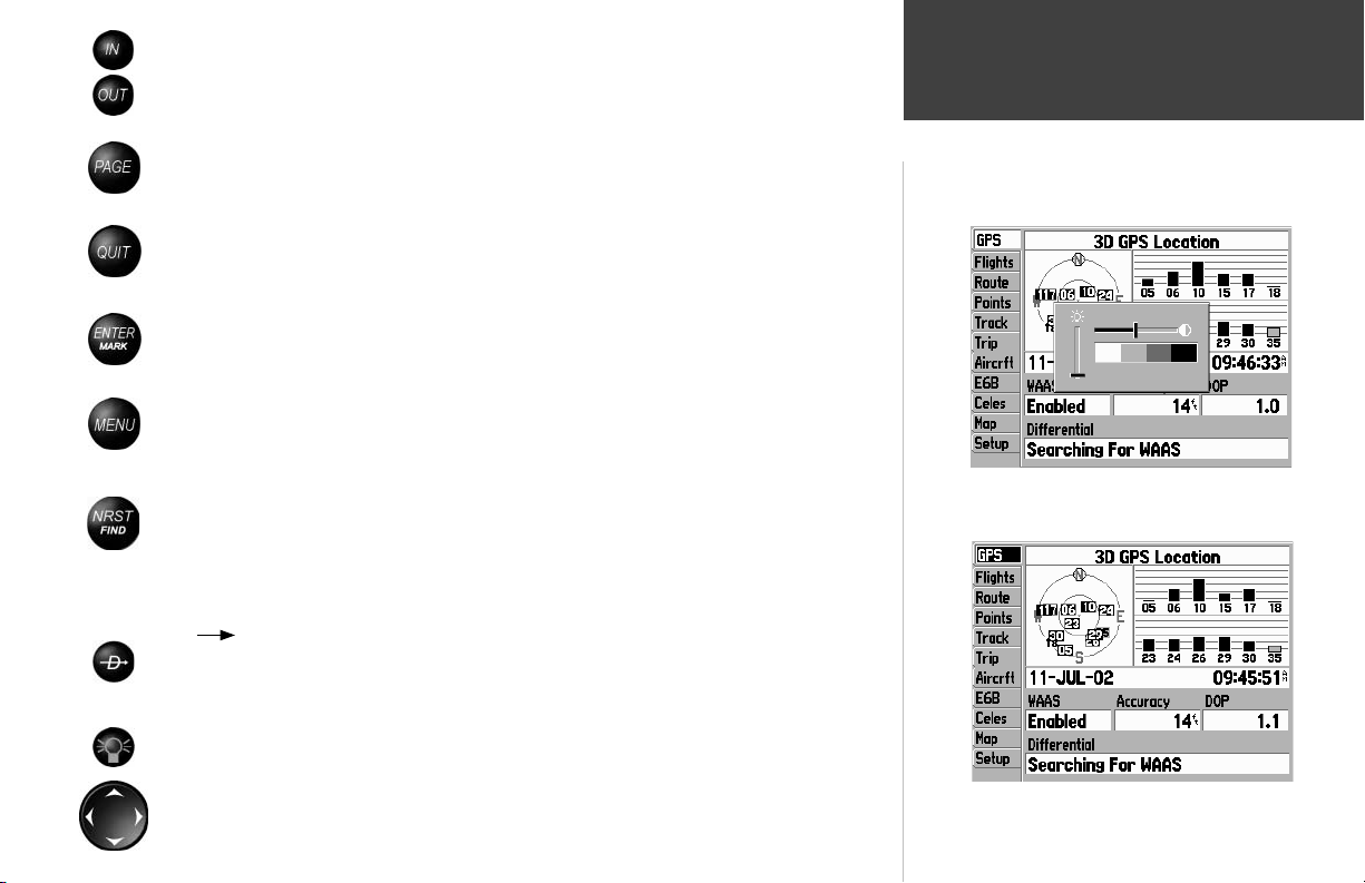
TheIN key — adjusts the map scale to show a smaller area with more detail. (Zooms in)
The
OUT
key — adjusts the map scale to show a larger area with less detail. (Zooms out)
The
PAGE
key — cycles the unit through the main display pages in sequence and returns
the display from a submenu page. Press and hold to select between Aviation, Land and Water
modes.
The
QUIT
key — cycles the unit through the main display pages in a reverse sequence,
restores the previous value in a data entry fi eld, or cancels an unintended function.
The
ENTER
key — selects a highlighted menu option. When entering data, allows you to
initiate entry, and then to accept the selected value(s). Press and hold to mark the current
location as a user-created waypoint.
The
MENU
key — displays a menu of available options for the current page. Pressing the
MENU key twice will display the Main Menu.
The
NRST/FIND
key — displays the nearest airports, navaids, points of communication and
airspace boundaries in Aviation Mode. In other modes (or when pressed multiple times in
Aviation Mode), displays the Find Menu to select Points of Interest, Addresses, user-created
waypoints, Cities and more for review or as a destination. Points of Interest and Address
information are provided from optional MapSource City Select or MetroGuide CDs.
TheD ( Direct To) key — allows you to retrieve airports, navaids, recently used waypoints
or user-created waypoints as a ‘Goto’ destination. Press and hold to display additional information for the current destination (such as communication frequency and runway data).
Basic Operation
Keypad Usage
With the GPSMAP 196 on, press the red POWER key to display a
settings window for backlighting and screen contrast.
The
POWER
key — is used to turn the unit on and off, to activate the backlight and to adjust
screen contrast.
The
ARROW KEYPAD
— controls movement of the on-screen cursor (highlight), pans the
Map Page, selects options and allows you to enter data (such as airport identifi ers).
Press the MENU key twice to display the Main Menu.
1

Basic Operation
Features / Data Entry
Example of on-screen cursor and data entry.
1. Use the ARROW KEYPAD to place the
cursor on the waypoint name fi eld.
2. Press ENTER.
3. Press RIGHT on the ARROW KEYPAD
to move to the second character. Then
UP/DOWN on the ARROW KEYPAD to
select the desired character.
4. Press RIGHT on the ARROW KEYPAD
to move to the third character. Then UP/
DOWN to select the desired character.
5. Press ENTER to complete data entry.
Example of cursor and on-screen button. The cursor is highlighting
the on-screen ‘Goto’ button. Press ENTER to select.
2
The following features and data entry procedures are referred to throughout this manual.
CURSOR— A highlighted area on the screen (white text on black background) which can be moved
up/down/left/right with the ARROW KEYPAD to select individual fi elds on the display. Moving the
cursor to a given location allows you to begin data entry or scroll through a list.
FIELD— The location on a page (such as “waypoint name fi eld”, shown at left) where a group of
characters or an option is entered and displayed. The cursor is placed on a fi eld (using the ARROW
KEYPAD) to begin data entry or selection of options.
To enter data in a data fi eld:
1. Use the ARROW KEYPAD to highlight the desired data fi eld.
2. Press ENTER to begin data entry.
3. Use the ARROW KEYPAD to enter the desired data. UP/DOWN to select the desired character and
RIGHT to move to the next character fi eld. LEFT allows you to back up to the previous character fi eld
or, when at the leftmost character fi eld, to clear the entire data fi eld.
4. Once the desired data has been entered, press ENTER to confi rm.
ON-SCREEN BUTTON— Similar to “Field”. Place the cursor on a button and press ENTER to select
the action corresponding to that button. An example of an on-screen button is the “GOTO” button
appearing at the bottom of the waypoint information pages.
SCROLL BAR— When viewing a list of items too long to display on a single page, a scroll bar will
appear along the right-hand side of the list. The position of the scroll bar indicates which portion of the
list is currently being displayed. The height of the scroll bar indicates the number of items in the list.
To scroll through a list of items, use the UP/DOWN portion of the ARROW KEYPAD.
DEFAULT— A system-selected format, built into the operating software or the unit’s memory, that will
be followed unless the user chooses a different setting. For example, the default setting for speed readings (in Aviation Mode) is ‘knots’, but can be changed to ‘miles per hour’ or ‘kilometers per hour’. Once
a setting is changed, the new setting is retained until another change is made or a ‘Restore Defaults’
menu option is selected.

To turn the GPSMAP 196 on, press and hold the RED POWER KEY.
A Welcome Page will appear while the unit conducts a self test. Once testing is complete, the Welcome Page is replaced by a Database Page. The Database Page shows the effective dates for the Jeppesen
database and a warning that the GPSMAP 196 is for VFR use only.
Press ENTER to acknowledge the Database Page.
The Satellite Status Page will appear as the GPSMAP 196 looks for available satellites. The
GPSMAP 196 continuously collects and stores “almanac” data when it receives a satellite(s). Almanac
data tells the GPS receiver where to look for each GPS satellite in the constellation. Each time you turn
the GPSMAP 196 on, it will use this almanac data—along with last known position, date and time—to
determine which satellites should be in view.
A minimum of three satellites is required for a two-dimensional position fi x (2D Navigation),
whereas at least four satellites are necessary for a three-dimensional position (3D Navigation). A threedimensional position includes latitude, longitude and altitude. Additional satellites are occasionally
needed to triangulate your position and, even if not needed to determine a position, additional satellites
will also improve position accuracy.
During normal use, expect a position fi x in 30-45 seconds. Once a suffi cient number of satellites are
received, the GPSMAP 196 will automatically transition from the Satellite Status Page to the Map Page.
Your position will appear on the map and, once you select a destination, the GPSMAP 196 will be ready
to help you navigate.
If you press any keys while the unit is acquiring satellites, the automatic sequencing from
)
Satellite Status Page to Map Page will not occur.
After the initial Welcome Page, the Database Page appears indi-
cating the database coverage area and effective dates.
Basic Operation
Turning the Unit On/Off
At the end of the day, when you’re fi nished using the GPSMAP 196, the same RED POWER KEY
that you use to turn the unit on also turns the unit off.
To turn the GPSMAP 196 off, press and hold the RED POWER KEY.
An additional page will appear in the start up sequence when an
optional data card and MapSource data are installed.
3

Basic Operation
Initializing the GPS Receiver
If satellites are NOT received after several minutes of operation,
the ‘Poor Satellite Reception’ window will appear. Select ‘New
Location’ to update your current position (from last known) or
‘Continue Acquiring’ to keep searching.
Initialization Options
If the GPSMAP 196 is unable to determine its location, an options menu will be displayed.
Depending on the situation, select the appropriate option to help the unit acquire satellites.
Start Simulator—
This option will turn the GPS receiver OFF. Select this option if you are indoors
and can not receive satellite signals, or if you wish to practice using the unit in simulator mode. This
option saves battery power and allows the map to redraw faster.
New Location—
If you have traveled to another state, province or country, and you are having
trouble locking on to satellites, select ‘New Location.’ Another menu will be displayed with the
options ‘Automatic’ or ‘Use Map.’ If ‘Automatic’ is selected, the unit switches to AutoLocate mode
and begins searching for satellites. If ‘Use Map’ is selected, use the pointer on the Map page to select
your approximate location and the unit will continue to acquire satellites normally. ‘Automatic’ may
take longer to acquire satellites.
Stored w/o Batteries—
If you have stored the unit without batteries, the date stored in the GPS
may be incorrect. To check the date, highlight ‘Stored w/o Batteries’ and verify the date displayed
below the options menu. If the date is incorrect, select ‘Stored w/o Batteries’ and press ENTER to
search for satellites.
Continue Acquiring—
Select this option if you are in an area where the satellites are temporarily
being blocked.
For more information on the GPS information screen see page 59.
4
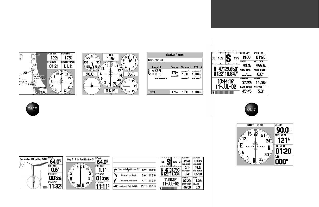
The GPSMAP 196 features four main pages which are linked together, in series. You can quickly
cycle through these main pages—in either direction—using the PAGE and QUIT keys. Each of these
main pages is described in greater detail on the following pages.
To display the next page in the sequence, press PAGE.
Basic Operation
To display the previous page in the sequence, press QUIT.
Map Page
Panel Page Active Route Page
!!!
The above sequence illustrates the pages you’ll see in Aviation Mode. As you become more familiar
with the GPSMAP 196, you’ll fi nd that using both PAGE and QUIT allows you to quickly select the
desired page. For example, to quickly jump from the Map Page to the Panel Page, press PAGE. To
return from the Panel Page to the Map Page, press QUIT.
In Land Mode, the sequence of pages is slightly different:
Main Page Sequence
Position Page
!!!
You can select the HSI Page to appear in the main page
sequence in place of the Panel Page.
Map Page
RMI Page
Current Route Page
Position Page
5
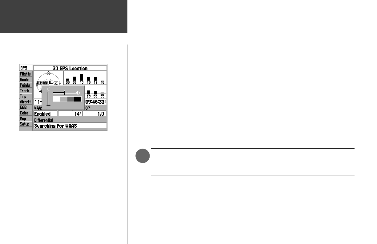
Basic Operation
Screen Backlighting / Contrast
Press the red POWER key to display a pop-up window for back-
lighting and contrast adjustments. Use the ARROW KEYPAD to
make the desired changes: UP/DOWN to change backlight level
and LEFT/RIGHT to change screen contrast.
The GPSMAP 196’s backlighting illuminates the display and keypad for optimal visibility. There are
twenty levels of screen backlighting, providing maximum fl exibility. At night, you can easily turn the
backlighting level down to prevent unwanted glare and distraction.
Screen contrast is adjustable as well. You may fi nd it necessary to adjust the contrast setting as the
ambient temperature changes.
Backlighting and screen contrast are adjusted using the RED POWER KEY and the ARROW
KEYPAD. A pop-up window shows the current settings and the progress of any adjustments you
have made.
To adjust the screen backlighting and contrast:
1. From any page, press the RED POWER KEY momentarily. A pop-up window will appear showing the
current contrast and backlighting settings.
2. Press the UP/DOWN portion of the ARROW KEYPAD to change the backlighting settings. UP will
increase backlight intensity; DOWN will decrease backlight intensity.
3. Press the LEFT/RIGHT portion of the ARROW KEYPAD to adjust screen contrast. LEFT will make
screen contrast lighter; RIGHT will make screen contrast darker.
4. Press ENTER to accept any changes and remove the screen settings window. Alternatively, if no keys
are pressed, the screen settings window will automatically be removed after fi ve seconds.
On warmer days you may fi nd it necessary to decrease the contrast setting for optimal
)
screen clarity. Conversely, on cold days it may be necessary to increase the contrast setting
to make screen information more legible.
6

Your GPSMAP 196 is designed to be fl exible. The unit provides “ Aviation Mode”, “ Land Mode” and
“Water Mode” settings, allowing you to tailor many features specifi cally for airborne, automotive or
marine applications.
In Land or Water modes, some alert messages—which would be appropriate in the cockpit—are
disabled to prevent nuisance messages not applicable to the current use. Additionally, there are many
settings on the GPSMAP 196 you can make on your own. For example, speed can be displayed in
knots, miles per hour or kilometers per hour. The GPSMAP 196 provides the fl exibility to have separate
settings for each mode (and saves them in memory so you do not have to re-enter them the next time
you switch between modes).
The list below describes the differences you will observe when switching between modes.
VEHICLE SYMBOL—An airplane symbol indicates your current position on the map in Aviation Mode. In
Land or Water modes, a pointer symbol is used.
MAP SETTINGS—All map settings, such as level of detail, North reference (North Up, Track Up, etc.), Auto
Zoom min/max limits, and text size will be saved by mode. When you switch between modes, your preference settings for each mode are retained and used for the map display.
GOTO NAVIGATION—In Aviation Mode, when a GOTO is initiated the course line (and course guidance) is
fi xed at the point where you started the GOTO. By contrast, in Land or Water modes, the GOTO course line
is always tied to your current position and moves as you move.
UNITS OF MEASURE—Your preferred settings for speed, altitude, distance and temperature are retained
for each mode. This makes it easy to switch between, for example, miles/miles per hour in Land Mode and
nautical miles/knots in Aviation and Water modes.
PAGE LAYOUT—The main pages can be custom-tailored to your preferences by changing the page layouts.
You may fi nd that you prefer different page layouts for different modes (applications) and the GPSMAP
196 will save your page layouts for each mode so they are ready the next time you select that mode.
APPROACH/ARRIVAL ALARMS—Each mode allows you to confi gure the unit for a different application. In
each of these modes you will likely be operating at signifi cantly different speeds. For this reason, you may
fi nd it useful to have different alarm time or alarm distance settings in each mode.
RECENT LIST—A separate list of recently used destinations is kept for each operating mode.
Basic Operation
Aviation, Land and Water Modes
Map Page and graphic HSI in Aviation Mode.
RMI Page in Land Mode.
7

Basic Operation
This page intentionally blank.
8
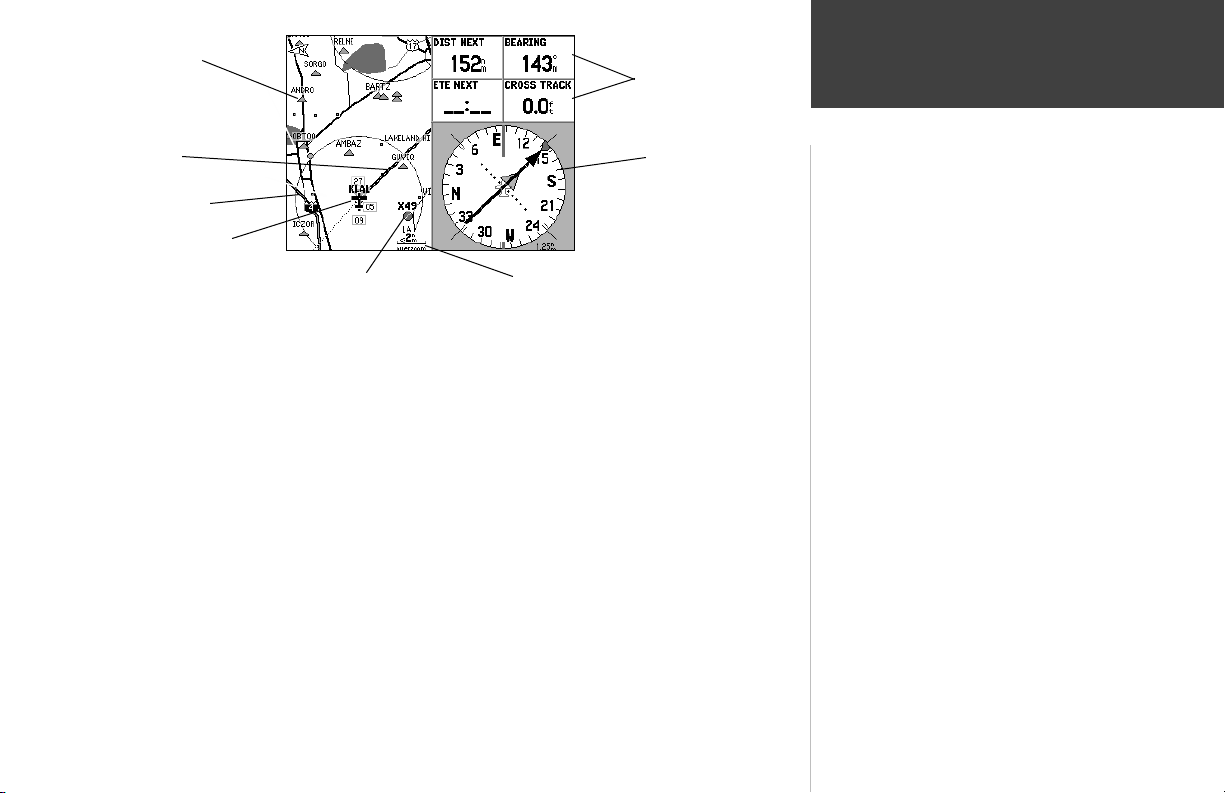
Nearby
Intersection
Selectable
Data Fields
Main Pages
Course Line
Interstate Highway
Current
Location
Nearby Airport
Map Scale
The GPSMAP 196 features a real-time moving map that can do much more than just plot your
course. The Map Page displays digital cartography (map information) which includes airspace boundaries, airports, navaids, lakes, rivers, coastlines, cities and highways. An on-screen cursor lets you pan
ahead to other map areas, determine distance and bearing to any map position, and retreive database
information directly from the map. Dedicated zoom keys are provided for instantaneous scale adjustments.
The map portion of the page displays your present position using an aircraft symbol (in Aviation
Mode) or a pointer symbol (in Land or Water modes). Your planned route appears on the map as a bold
line, and your track log (which shows where you’ve been) appears as a series of small points. You may
select which features are shown on the Map Page using the Map Page Options, described on page 14.
Graphic HSI
The Map Page graphically depicts your present position relative
to nearby airports, navaids, airspace boundaries, lakes, rivers,
towns and more.
During normal use, your position remains fi xed at the center of
the screen, and the map information moves (scrolls) on the map
as you move.
If you wish to view information outside the current area, you can
either:
• change the map scale using the IN and OUT zoom keys,
and/or
• pan to the area you want to see using the ARROW KEYPAD.
(NOTE: When panning, you can return to normal map operation
and re-center the map to your position by pressing QUIT.)
By default, four user-selectable data fi elds appear on the right-hand side of the screen—along with
a graphic HSI. The HSI works much like a mechanical HSI, indicating the desired course and your
deviation left/right of this course. If the needle points straight up and the course deviation needle is
centered, you are heading directly to your destination. From the Map Page Options, each data fi eld may
be confi gured to display any one of 40 possible data options. You can also add additional data fi elds to
the page or select a full screen map without data fi elds, using the Map Page Options (see page 14).
Map Page
What is it?
How does it work?
9
Main Pages
Map Page
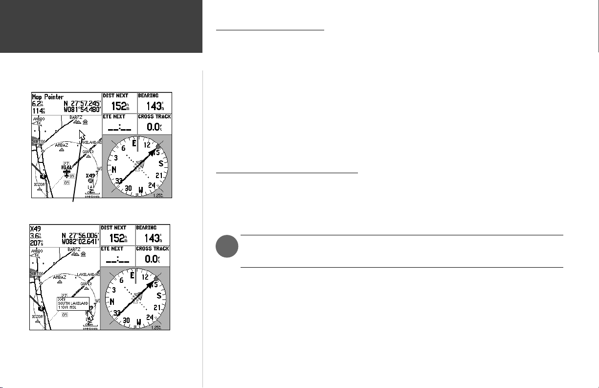
Use the ARROW KEYPAD to pan the map. When panning a
pointer appears on the map.
Place the pointer on a map feature to display additional informa-
tion. For waypoints, airports or navaids, press ENTER to
display a waypoint information page for the selected point.
10
Map Page Operating Modes
Two basic map operating modes, position mode and panning mode, determine what information is
shown on the map display. Position mode pans the map to keep the present position symbol centered in
the display area, and is the normal mode of operation when viewing the Map Page. Panning mode pans
the map to keep the pointer within the display area, and is used to view map information outside your
current area (without changing scales), measuring distance to map features from your current position
or for retrieving database information from the map. The GPSMAP 196 will always power up in the
position mode, with the last known location centered on the map display. With the Map Page displayed,
pressing the ARROW KEYPAD will activate panning mode.
When the pointer is active, an additional data window will appear at the top of the screen to indicate the position, range and bearing to the pointer or a selected waypoint or map item.
Using Panning Mode and the Pointer
The pointer allows you to pan away from your present position and scroll to other map areas around
the world. As you pan past the edge of the current map display, the screen will actively scroll forward
to provide continuous map coverage. (Keep in mind that the present position symbol moves with the
scrolling map, and may not be visible on the display screen.)
NOTE: When the pointer reaches the edge of the map, the unit may pause briefl y as it
)
loads new map data.
To move the pointer:
1. Press the ARROW KEYPAD to move the pointer in an up, down, left or right direction.
As you move the pointer, the distance and bearing from your present position to the pointer will be
displayed in the data window, along with the cursor’s position coordinates. In panning mode, zooming in or out will center the pointer on the screen. When the pointer is stationary, a fi xed coordinate
position will appear in the position fi eld, and the distance and bearing from your present position will
change as your vehicle moves.

To eliminate the cursor and re-center your position on screen:
1. Press the QUIT key. The unit will return to position mode and the present position symbol will appear
centered on the map.
The cursor may also be used to ‘snap’ to on-screen waypoints and map items. When a waypoint
name is highlighted, you can review information about the waypoint, list waypoint options, or execute a
GOTO right from the Map Page.
To select an on-screen airport, navaid or map item with the cursor:
1. Use the ARROW KEYPAD to move the cursor to the desired waypoint or map item (if there are
several waypoints grouped closely together, zoom in closer for a better view).
2. When a waypoint or map item is selected, it will become highlighted on screen, with the name and
position displayed at the top of the screen.
3. To view additional details, press ENTER. If the item is an airport, fi le tabs will appear across the top
of the page. This allows you to quickly review fi eld elevation, runway layout, communication frequencies and available approaches. (Multiple fi le tabs will also appear if more than one object appears on
the map at the pointer location.) To save a map item as a waypoint, press MENU and select ‘Create
Waypoint’.
With the pointer on a map feature, press the DIRECT TO key
To GOTO an on-screen airport, navaid or map item:
1. Follow steps 1 through 3 above to display additional details for the on-screen item.
2. Use the ARROW KEYPAD to highlight the ‘GOTO’ button at the bottom of the screen. With this
button highlighted, press ENTER.
The cursor may also be used to create a new waypoint directly from the map. If nothing currently
exists at the map pointer position, a new waypoint will be created at the cursor’s location.
To create a waypoint with the cursor on an open map location:
1. Use the ARROW KEYPAD to move the cursor to the desired map position.
2. Press and quickly release the ENTER/MARK key to capture the cursor location (Pressing and holding
the ENTER/MARK key will capture the current location, not the cursor’s location).
3. The ‘New Map Waypoint’ window will appear. With ‘OK’ highlighted, press ENTER to confi rm the
new waypoint using the default three-digit name and symbol. (You can also change the waypoint
name and symbol as described on page 48.)
Main Pages
Map Page
(then ENTER) to navigate to that point.
Creating a New Map Waypoint
11
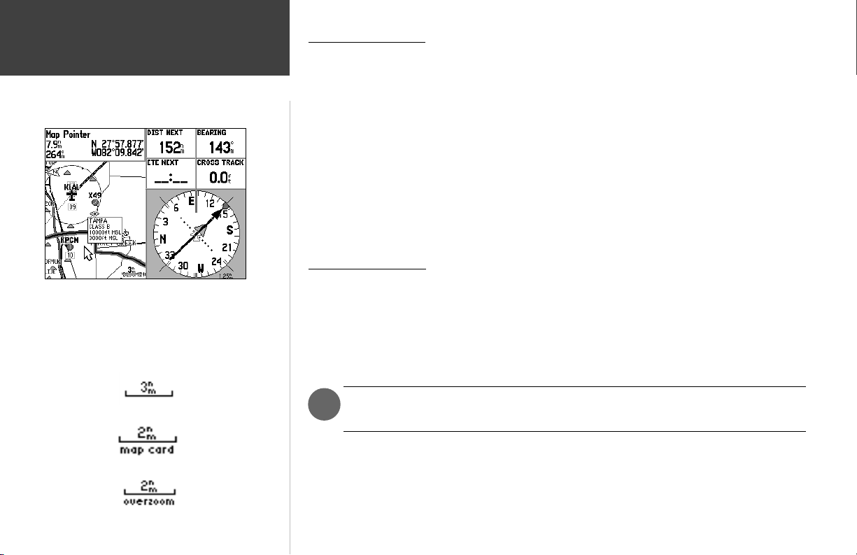
Main Pages
Map Page
When the pointer is placed inside an airspace boundary, the
boundary is highlighted and a text box appears. The text box
indicates airspace type and fl oor/ceiling limits. Press ENTER to
display additional airspace information.
Map scale info appearing at the bottom of the page:
Airspace Information
Cursor mode may also be used to retrieve information on airspaces depicted on the map. Once the
panning pointer is placed on an open area within an airspace, the entire airspace (or airspace sector) is
highlighted. A text box adjacent to the panning pointer will indicate the airspace type and fl oor/ceiling
limits. Additional information, including communication frequencies, is available from an information
page.
To retrieve airspace information from the Map Page:
1. Use the ARROW KEYPAD to select an open area within the desired airspace’s boundary. The boundary line is highlighted and a window appears showing airspace type and fl oor/ceiling limits.
2. To display additional information, such as controlling agency, press ENTER. Communication frequencies may then be displayed by highlighting the on-screen “Frequencies” button and pressing ENTER.
Or, with the on-screen “OK” button highlighted, press ENTER to return to the Map Page.
Selecting Map Scales
The map display has 28 available range scales from 20 ft. to 800 mi. (5 m to 1200 km). The map
scale is controlled by the IN and OUT keys, with the current scale displayed at the bottom right of the
data window.
To select a map scale:
1. Press the OUT key to zoom out and the IN key to zoom in.
12
Using Built-In Basemap
Using MapSource Data
Overzoom, no additional data
The scale value represents the distance from one end of the scale bar to the other, not
)
across the entire screen.

The GPSMAP 196 has a built-in worldwide map displaying detail to a 20 mile scale. More detailed
coverage is available through the use of optional MapSource CD-ROM data. The GPSMAP 196 will
display cartography as long as there is map information available for the range you’ve selected.
Map coverage will conform to the following conditions:
• When the selected zoom range is covered by either the internal map or MapSource CD data, cartography will be displayed.
• When the selected zoom range is covered by both the internal map and MapSource CD data, cartography will be displayed using the data with the best resolution.
• When the selected zoom range exceeds the resolution of the data in use, an ‘overzoom’ warning will
appear below the scale fi eld.
Easy Screen Decluttering
You can select the desired level of map detail using the ‘Setup Map’ option described on the following page. You may, however, wish to temporarily remove some map detail in congested areas without
making any changes to the map settings. There are four declutter settings which will display everything,
remove the background detail (lakes/rivers/highways), remove airspace boundaries, and—at the highest
declutter level—remove all map detail except those waypoints which are part of your selected route.
Map decluttering is selected with the ENTER key, and only works in Position Mode (see next page for
decluttering in Cursor Mode).
To quickly declutter the Map Page (Aviation Mode only):
1. Press ENTER. Background detail—including highways, cities, rivers & smaller lakes—is displayed in
gray (de-emphasized) on the map to make the aviation data easier to read. This declutter setting is
identifi ed by ‘CLEAR-1’ appearing below the map scale.
2. Press ENTER again. The above background map detail is removed from the map display. ‘CLEAR-2’
appears below the map scale.
3. Press ENTER again. Airspace boundary detail is removed from the map display. ‘CLEAR-3’ appears
below the map scale.
4. Press ENTER again. Only the waypoints/navaids which are part of the current GOTO or route appear
on the map display. ‘CLEAR-4’ appears below the map scale.
5. Press ENTER again to return ALL detail to the map display.
Main Pages
Map Page
First declutter level with background (basemap) detail in gray.
Second declutter level with background detail off. Note the
‘Clear-2’ declutter indication below the map scale.
13

Main Pages
Map Page Options
With the Map Page displayed, press MENU to display context-
sensitive options for this page. Use the ARROW KEYPAD, then
ENTER to select the desired option.
Many features of the GPSMAP 196 are menu driven. Each of the main pages has an options menu,
allowing you to custom tailor the corresponding page to your preferences and/or select special features
that specifi cally relate to that page. The data window, located at the right side of the display, provides a
user-selectable layout of various types of useful data. Each data fi eld may be confi gured to display any
one of several data options. The data window layout may also be customized to change the actual size
of the data displayed. The GPSMAP 196’s Map Page options menu provides access to functions and
features relating to the Map Page and options for layout of the page.
To display the Map Page options, press MENU (with the Map Page displayed).
To select a menu option, use the ARROW KEYPAD to highlight the desired option and
press ENTER.
The following options are available:
• Declutter/Declutter Off • Full Screen Map/Show Data Fields
• Measure Distance • Setup Page Layout
• Change Data Fields • Setup Map
• Hide Directions/Show Directions (land mode only)
• Declutter/Declutter Off— provides the same screen decluttering capability as described on page 13.
The current declutter setting is indicated directly below the map scale. This option is useful when in
Cursor Mode, as the ENTER key in cursor mode is used to display database information or create a
new waypoint.
To select a declutter setting:
1. Highlight the ‘Declutter’ (or ‘Declutter Off’) option and press ENTER. Note the declutter setting, as
indicated directly below the map scale.
14

• Full Screen Map/Show Data Fields— toggles between a full screen map without data fi elds, or a
map with data fi elds on the right-hand side of the page.
To maximize the map/show data fi elds:
1. Highlight the ‘Full Screen Map’ option and press ENTER. The Map Page will now be maximized with
no data fi elds. OR,
1. Highlight the ‘Show Data Fields’ option and press ENTER. The Map Page will display the map with
data fi elds along the right-hand side of the page.
• Measure Distance— allows you to measure the bearing/distance between two points on the map.
To measure the Bearing/Distance between two points:
1. Highlight the ‘Measure Distance’ option and press ENTER. An on-screen pointer will appear on the
map display at your present position with ‘ENT REF’ below it.
2. Move the cursor to the desired reference point (the point that you want to measure from) and press
ENTER.
3. Move the cursor to the point you want to measure to. The bearing and distance from the reference
point and cursor coordinates will be displayed in the data window at the top of the display.
4. Press the QUIT key to fi nish.
• Setup Page Layout— provides Map Page display options for four large-text data fi elds, ten smallertext data fi elds or four data fi elds with an HSI (or RMI in Land/Water modes).
To setup the page layout:
1. Highlight the ‘Setup Page Layout’ option and press ENTER.
2. Select the desired option, None, 1 Column (Large), 2 Columns (Small), or 2 Columns with HSI (RMI),
and press ENTER.
Main Pages
Map Page Options
The ‘Full Screen’ option displays a full screen map without the
data fi elds or graphic HSI.
Use the ‘Measure Distance’ option to measure distance between
two points. Bearing and distance appears at the top of the page.
15
Main Pages
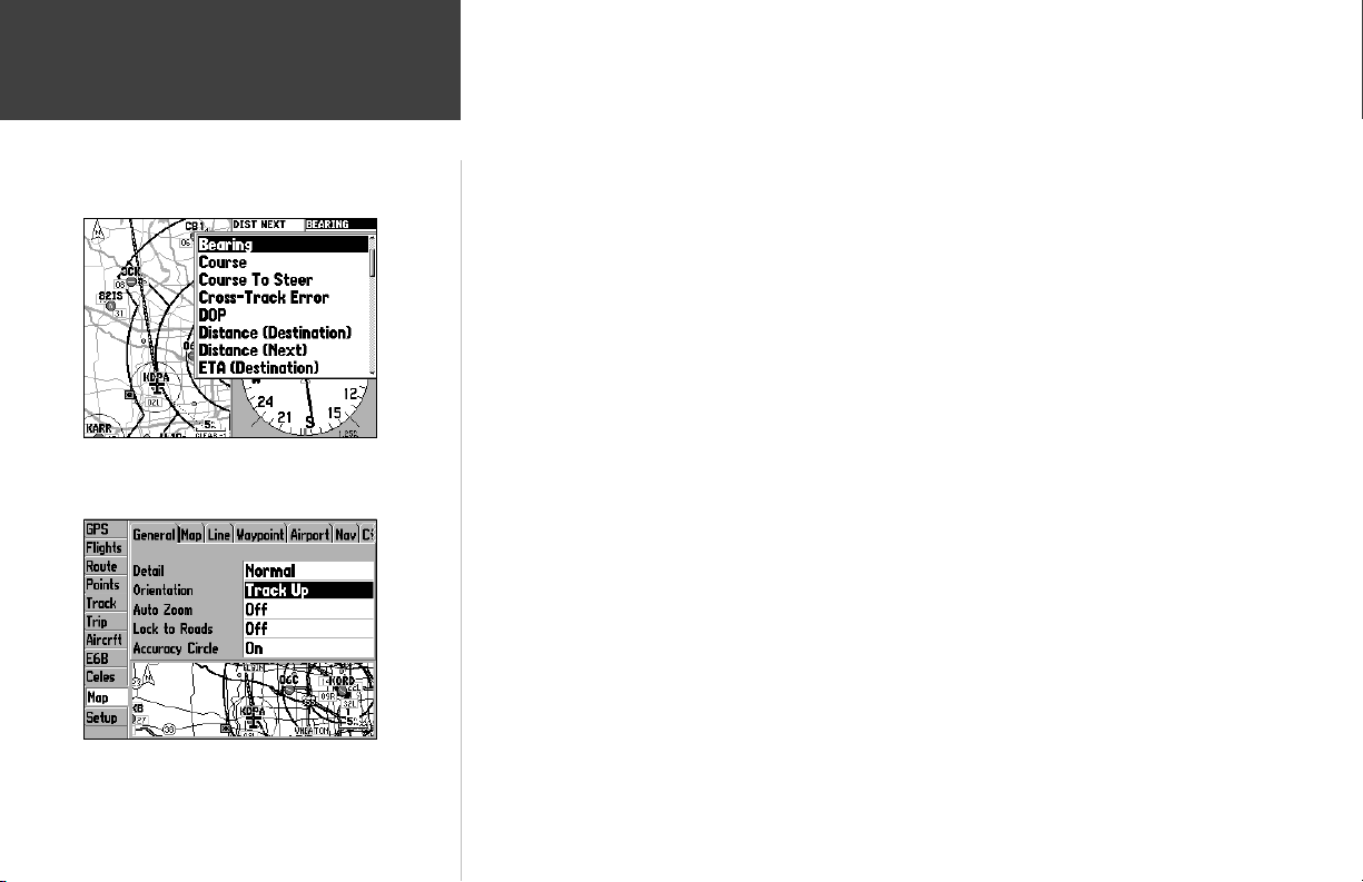
Map Page Setup Options
Select ‘Change Data Fields’, highlight the fi eld you wish to change
and press ENTER to diplay a list of available data types.
• Change Data Fields— allows you to specify the type of data displayed in each data fi eld appearing on the Map Page. There are over forty different data options including: altitude, bearing, course,
distance, ETA, ETE, speed, track and a pointer. You can review the complete list on the GPSMAP 196,
and refer to Appendix D for defi nitions of each data fi eld term.
To change a data fi eld:
1. Use the ARROW KEYPAD to highlight the ‘Change Data Fields’ option and press ENTER.
2. Move the fi eld highlight to the data fi eld you want to change and press ENTER.
3. Move up or down on the list using the ARROW KEYPAD to highlight the data you want to display,
and press ENTER to select. To exit, press QUIT.
• Setup Map— jumps to the Map tab of the Main Menu, allowing you to confi gure the map display
to your preferences. Settings include map detail, map orientation, auto zoom, text size and maximum scale for each map item to appear. The ‘Auto’ setting available for many map items allows you
to control all map features globally using the ‘Detail’ setting (see below). The map setup options are
organized under a series of ‘fi le tabs’ which appear at the top of the page. The fi le tabs make individual
selections easier to locate and change.
To change a map setup feature:
1. From the Map Page menu, highlight ‘Setup Map’ and press ENTER.
2. Move LEFT or RIGHT on the ARROW KEYPAD to highlight the desired fi le tab, then UP or DOWN on
the ARROW KEYPAD to highlight the setting you want to change and press ENTER.
3. Move UP or DOWN on the ARROW KEYPAD to highlight to the desired setting and press ENTER.
4. To exit, press QUIT.
Selecting ‘Setup Map’ places you on the ‘Map’ tab of the Main
Menu. From there, use the ARROW KEYPAD to select the
desired map setup tab across the top of the page.
16

The following table lists the fi le tabs and the settings available under each tab:
General Tab
Detail— Most, More, Normal, Less, Least: controls how much map detail you will see. This setting
only applies to map features set to ‘Auto’. Those features which have a specifi ed maximum scale or are
turned ‘Off’ will not be affected by this setting.
Orientation— North Up: fi xes the top of the map display to a north heading; Track Up: fi xes the top
of the map display to the current track heading; Course Up: fi xes the map so the direction of navigation is always “up” and turns the navigation leg line vertical on the screen.
Auto Zoom— On/Off: when ‘On’ the map will automatically adjust the map scale as you approach
your destination. Auto Zoom attempts to zoom in/out to the next step when it can still display your
location and the destination at the next higher/lower scale setting.
Accuracy Circle/Lock to Roads— On/Off: toggles the accuracy circle or lock to road feature ‘On’ and
‘Off’. The accuracy circle represents the approximate position accuracy of the unit based on satellite
conditions. Your position will be within the circle. The lock to roads feature is used with MapSource
MetroGuide or City Select data and locks your present position icon to the nearest road.
Map Tab
Aviation Data— On/Off: turns all Jeppesen data (airports, navaids and airspace boundaries) on or off.
Basemap— On/Off: turns the built-in basemap (cities, highways, lakes and rivers) on or off.
Lat/Lon Grid— Off, Auto, 20 ft.-800 mi: sets the maximum scale at which latitude/longitude grid lines
will appear on the screen or shuts the feature off.
Grid Labels— Off, Auto, 20 ft.-800 mi: sets the maximum scale at which labels for latitude/longitude
grid lines will appear on the map.
Map Outlines— On/Off: toggles the coverage boxes for optional MapSource map data ‘On’ and ‘Off’.
The map outlines allow you to easily identify the area of coverage for any MapSource map data shown
on the map display.
Main Pages
Map Page Setup Options
The ‘General’ Tab includes settings for level of detail and for map
orientation. ‘Track Up’ orientation will rotate the map to keep the
top aligned to your current direction of travel (track).
From the ‘Map’ Tab, you can use the ‘Basemap’ setting to turn
On/Off the background map. ‘Map Outlines’ will show the
boundaries of any optional MapSource data.
17

Main Pages
Map Page Options
Use the ‘Line’ tab to remove/display the active track log or any
saved track logs.
The ‘Airport’ tab lets you display runway numbers and/or
runway extensions, or turn these map features off.
18
Line Tab
Heading Line— On/Off: turns the Heading Line on or off. A Heading Line is a projected line from
your current position which shows your current heading.
Bearing Line— Auto, Off, 20 ft.-800 mi.: sets the maximum scale at which the Bearing Line appears
on the screen. The Bearing Line shows the bearing from your current location to your destination.
Course Line— Auto, Off, 20 ft.-800 mi.: sets the maximum scale at which the Course Line appears on
the screen. The Course Line shows a direct navigation line from the point navigation was initiated to a
destination waypoint.
Track Log— Auto, Off, 20 ft.-800 mi.: sets the maximum scale at which the active Track Log appears
on the screen. A track log is an electronic bread crumb trail showing where you have been.
Saved Tracks— Auto, Off, 20 ft.-800 mi.: sets the maximum scale at which any saved Track Logs will
appear on the screen.
Waypoint Tab
Waypoints— Text Off, Small, Medium, and Large: controls the screen size of the waypoint name.
Zoom Auto, Off, 20 ft.-800 mi: sets the maximum scale at which user waypoints appear on the screen.
Active Route— Text Off, Small, Medium, and Large: controls the screen size of active route waypoint
names. Zoom Auto, Off, 20 ft.-800 mi: sets the maximum scale at which active route waypoints
appear on the screen.
Airport Tab
Large/Medium/Small Airport— Text Off, Small, Medium, and Large: controls the screen size of the
airport identifi er. Zoom Auto, Off, 20 ft.-800 mi: sets the maximum scale at which airports appear on
the screen. Large airports are those with a runway longer than 8000’. Medium airports are those with a
runway longer than 5000’ or with a control tower.
Runway Numbers— Text Off, Small, Medium, and Large: controls the screen size of runway numbers.
Zoom Auto, Off, 20 ft.-800 mi: sets the maximum scale at which runway numbers appear on the
screen.
Rnwy Extensions— Zoom Auto, Off, 20 ft.-800 mi: sets the maximum scale at which runway extensions appear on the screen.

Nav Tab
VOR— Text Off, Small, Medium, and Large: controls the screen size of the VOR identifi er. Zoom
Auto, Off, 20 ft.-800 mi: sets the maximum scale at which VORs appear on the screen.
NDB— Text Off, Small, Medium, and Large: controls the screen size of the NDB identifi er. Zoom
Auto, Off, 20 ft.-800 mi: sets the maximum scale at which NDBs appear on the screen.
Intersection— Text Off, Small, Medium, and Large: controls the screen size of the intersection name.
Zoom Auto, Off, 20 ft.-800 mi: sets the maximum scale at which intersections appear on the screen.
Ctrl Tab
Class B, CTA— Zoom Auto, Off, 20 ft.-800 mi: sets the maximum scale at which Class B or CTA
airspace appears on the screen.
Class C, TMA— Zoom Auto, Off, 20 ft.-800 mi: sets the maximum scale at which Class C or TMA
airspace appears on the screen.
Towers, Cntrl Zone— Zoom Auto, Off, 20 ft.-800 mi: sets the maximum scale at which Tower or
Control Zone (Class D) airspace appears on the screen.
SUA Tab
Restricted Areas— Zoom Auto, Off, 20 ft.-800 mi: sets the maximum scale at which restricted airspace
appears on the screen.
MOAs— Zoom Auto, Off, 20 ft.-800 mi: sets the maximum scale at which military operation areas
appear on the screen.
Mode C Veils— Zoom Auto, Off, 20 ft.-800 mi: sets the maximum scale at which Mode C veils appear
on the screen.
Other SUAs— Zoom Auto, Off, 20 ft.-800 mi: sets the maximum scale at which other airspace categories appear on the screen. ‘Other SUAs’ includes training, caution, danger, warning and alert areas.
Main Pages
Map Page Options
Use the ‘Nav’, ‘Ctrl’ and ‘SUA’ tabs to defi ne how navaids and
airspace boundaries will appear on the map display. The ‘Text’
setting determines the size of navaid names. ‘Zoom’ defi nes the
maximum scale at which the feature will appear.
19

Main Pages
Map Page Options
Use the ‘Road’ tab to defi ne how interstate highways, state high-
ways, local roads and railways will appear on the map.
City Tab
Large/Medium/Small City— Text Off, Small, Medium, and Large: controls the screen size of the city
names. Zoom Auto, Off, 20 ft.-800 mi: sets the maximum scale at which cities appear on the screen.
Large cities are those with approximate populations greater than 200,000 and medium cities are those
with approximate populations over 50,000.
Small Town— Text Off, Small, Medium, and Large: controls the screen size of the town names. Zoom
Auto, Off, 20 ft.-800 mi: sets the maximum scale at which towns appear on the screen. Small towns
have approximate populations under 5,000 or an unknown population size.
Road Tab
Freeway/ Highway/Local Road— Zoom Auto, Off, 20 ft.-800 mi: sets the maximum scale at which each
roadway category appears on the screen.
Local Road Name— Text Off, Small, Medium, and Large: controls the screen size of local road names.
Zoom Auto, Off, 20 ft.-800 mi: sets the maximum scale at which local road names appear on the screen.
Railroad— Text Off, Small, Medium, and Large: controls the screen size of railway names. Zoom Auto,
Off, 20 ft.-800 mi: sets the maximum scale at which railway lines appear on the screen.
Point Tab
POIs— Text Off, Small, Medium, and Large: controls the screen size of MapSource points of interest
names. Zoom Auto, Off, 20 ft.-800 mi: sets the maximum scale at which MapSource points of interest
appear on the screen. Optional MapSource POI information can include food, lodging, attractions,
entertainment, shopping and services.
Geo— Text Off, Small, Medium, and Large: controls the screen size of geographic point names. Zoom Auto,
Off, 20 ft.-800 mi: sets the maximum scale at which geographic points appear on the screen. Optional
MapSource geographic points include peaks, cemeteries, dams, marinas, boat ramps and golf courses.
Exit— Text Off, Small, Medium, and Large: controls the screen size of interstate highway exit names
or numbers. Zoom Auto, Off, 20 ft.-800 mi: sets the maximum scale at which interstate highway exits
appear on the screen.
The ‘Point’ tab includes settings for optional MapSource points of
interest (POIs) and geographic points (Geo).
20
 Loading...