

Page 1
VHF 300 Series Radio Installation Instructions
These installation instructions are for the following VHF radios and handsets:
North American Models International Models
VHF 300 VHF 300i
VHF 300 AIS VHF 300i AIS
GHS™ 10 GHS 10i
Throughout these instructions, both the VHF 300 and the VHF 300i will be referred to as the VHF 300 series radio, or “the radio”. The GHS 10
and the GHS 10i will be referred to as the GHS 10.
Compare the contents of this package with the packing list on the box. If any pieces are missing, contact your Garmin® dealer immediately.
Product Registration
Help us better support you by completing our online registration today. Go to http://my.garmin.com. Keep the original sales receipt, or a
photocopy, in a safe place.
Contact Garmin
Contact Garmin Product Support if you have any questions while using your VHF 300 series radio. In the USA, go to
www.garmin.com/support, or contact Garmin USA by phone at (913) 397.8200 or (800) 800.1020.
In the UK, contact Garmin (Europe) Ltd. by phone at 0808 2380000.
In Europe, go to www.garmin.com/support and click Contact Support for in-country support information, or contact Garmin (Europe) Ltd. by
phone at +44 (0) 870.8501241.
Warnings and Safety Notices
Antenna Mounting and EME Exposure
The VHF 300 series radio generates and radiates radio frequency (RF) electromagnetic energy (EME). Failure to observe these guidelines may
expose persons to RF radiation absorption exceeding the maximum permissible exposure (MPE).
Garmin declares an MPE radius of 59 in. (1.5 m) for this system, which was determined using 25 watts output to an omni-directional 9 dBi gain
antenna. The antenna should be installed such that a distance of 59 in. (1.5 m) is maintained between the antenna and all persons.
WARNING: Radio operators with cardiac pacemakers, life-support machines, or electrical medical equipment should not be exposed to excessive
radio-frequency elds.
WARNING: Operate the device in accordance with the instructions supplied.
CAUTION: Wear safety goggles and a dust mask when drilling, cutting, or sanding.
NOTICE: The device complies with internationally recognized standards covering human exposure to electromagnetic elds from radio devices.
NOTICE: Check with local authorities for any antenna or operational restrictions that may apply.
NOTICE: To prevent possible damage to your radio, the antenna must be connected to the radio before transmitting. This ensures that the power output
to the antenna port dissipates properly when transmitting.
Needed Tools
Drill and drill bits
•
#2 Phillips screwdriver
•
3 1/2 in. (90 mm) hole saw (for installing the active speaker)
•
Waterproof, adhesive tape (such as rubber vulcanizing tape)
•
May 2010 190-01098-02 Rev. C Printed in China
Page 2
Installing your VHF 300 Series Radio
1. Select locations for the radio components.
2. Install the transceiver box (page 3).
3. Install the active speaker (page 4).
4. Install the GHS 10 (page 5).
Although these options are not necessary to use your radio, these
instructions cover the following additional installation options.
Connecting the GHS 10 to a passive speaker (page 5)
•
Connecting the radio to a chartplotter or another GPS device
•
(page 5)
Connecting the radio to a hailer horn (page 7).
•
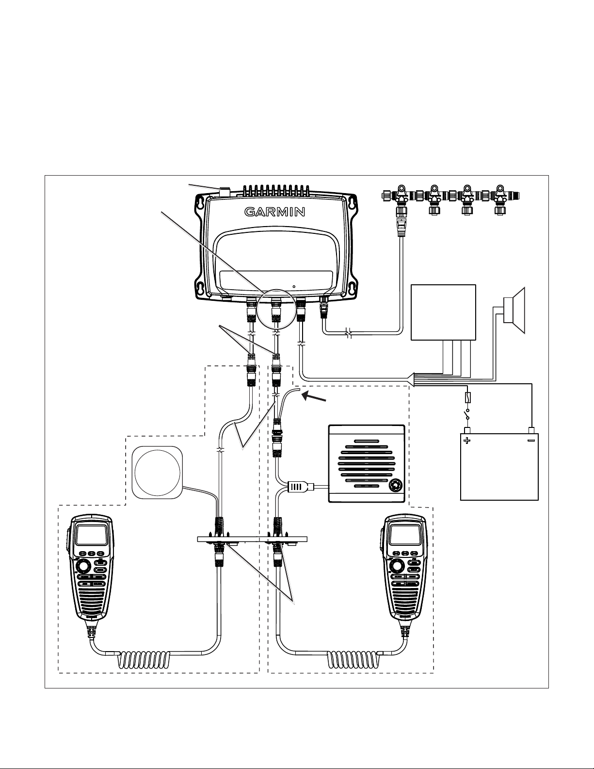
Selecting Locations for the VHF 300 Series Radio Components
Use the diagram to determine how to best organize the VHF 300 series radio components on your boat. Test to be sure the cables reach all
components before permanently mounting any component.
Antenna connector
GHS 10 station 1
This GHS 10 must
be located in the
wheelhouse or an
adjacent room per
FCC law.
GHS 10 cable
extension
(optional)
VHF 300 transceiver box
NMEA 2000 drop
cable (optional)
NMEA 2000 network
(optional)
NMEA 0183
device
(optional)
Hailer horn
(optional)
GHS 10
Passive
speaker
(not included)
GHS 10
cable
VHF 300 power/data cable
Clip and tape
bare wires
Active
speaker
cable
Bulkhead pass-through
GHS 10 active
speaker
plate
10 A
fuse
Switch
12 Vdc
GHS 10
GHS 10 with a passive speaker
VHF 300 Series Layout Diagram
GHS 10 with an active speaker
Notes:
Install the transceiver box in a dry, protected location.
•
2 VHF 300 Series Installation Instructions
Page 3
Connect the transceiver box to a 12 Vdc battery through an accessible switch.
-
+
•
Install the GHS 10 connected to station one on the transceiver box in the wheelhouse or an adjacent room per Federal Communications
•
Commission (FCC) law.
Ensure that you install each component of the VHF radio at least 20 in. (.5 m) from any compass. Test your compass to verify that it operates
•
correctly when the radio is operating.
Extension cables are available for the GHS 10 cable.
•
Installing the Transceiver Box
Install the transceiver box below deck on a bulkhead, in a location that is dry and protected from washdown. Ensure that the location is
well ventilated and away from objects that generate heat. Ensure that the transceiver box is at least 20 in. (.5 m) from any compass to avoid
interference.
Mounting the Transceiver Box
1. Ensure that the chosen location is dry, protected, and well-ventilated.
2. Use the template on page 11 to determine mounting holes.
3. Drill four 1/8 in. (3 mm) pilot holes.*
4. Mount the transceiver box using the included M4.2×25 screws. You can also use bolts, washers, and nuts (not included) to mount the
transceiver box if the mounting surface allows.
Connecting the Transceiver Box to Power
Use the VHF 300 power/data cable to connect the transceiver box to a 12 Vdc battery through an external switch.
Notes:
Use the VHF 300 Power Wiring-Assignment Table to identify the positive and negative wires.
•
The replacement fuse on the power/data wiring harness is a 10 A, slow-blow
•
fuse.
•
If it is necessary to extend the power wires, use at least 16 AWG wire.
If your boat has an electrical system, you might be able to wire the radio
•
directly to an unused holder on your fuse block. If you use the fuse block,
remove the in-line fuse holder supplied with the power/data cable.
Device Wire Color Function
Device Wire Color Function
VHF 300 power/data
VHF 300 power/data
cable
cable
VHF 300 Power Wiring-Assignment Table
VHF 300 Power Wiring-Assignment Table
Red Power—positive (+)
Red Power—positive (+)
Black Ground—negative (-)
Black Ground—negative (-)
NOTICE: Cover the connections with a waterproof, adhesive tape, such as rubber vulcanizing tape, to prevent water from seeping into the radio.
➋
Wiring the VHF 300 Through a Fuse Block
➌
➊
Boat ground
➋
10 A fuse
➌
To 10.8-15.6 Vdc boat supply
➍
To VHF 300 power/data cable
–
+
➊
➍
Connecting an Antenna to the Transceiver Box:
1. Mount the antenna on your boat according the instructions provided by the antenna manufacturer.
2. Connect the antenna to the antenna port on the transceiver box.
NOTE: The antenna port is on the opposite side of the transceiver box from the primary row of connectors pictured on page 4.
* A 1/8 in. (3 mm) pilot hole is nominal for plywood. Different dashboard materials my require a different size pilot hole.
VHF 300 Series Installation Instructions 3
Page 4
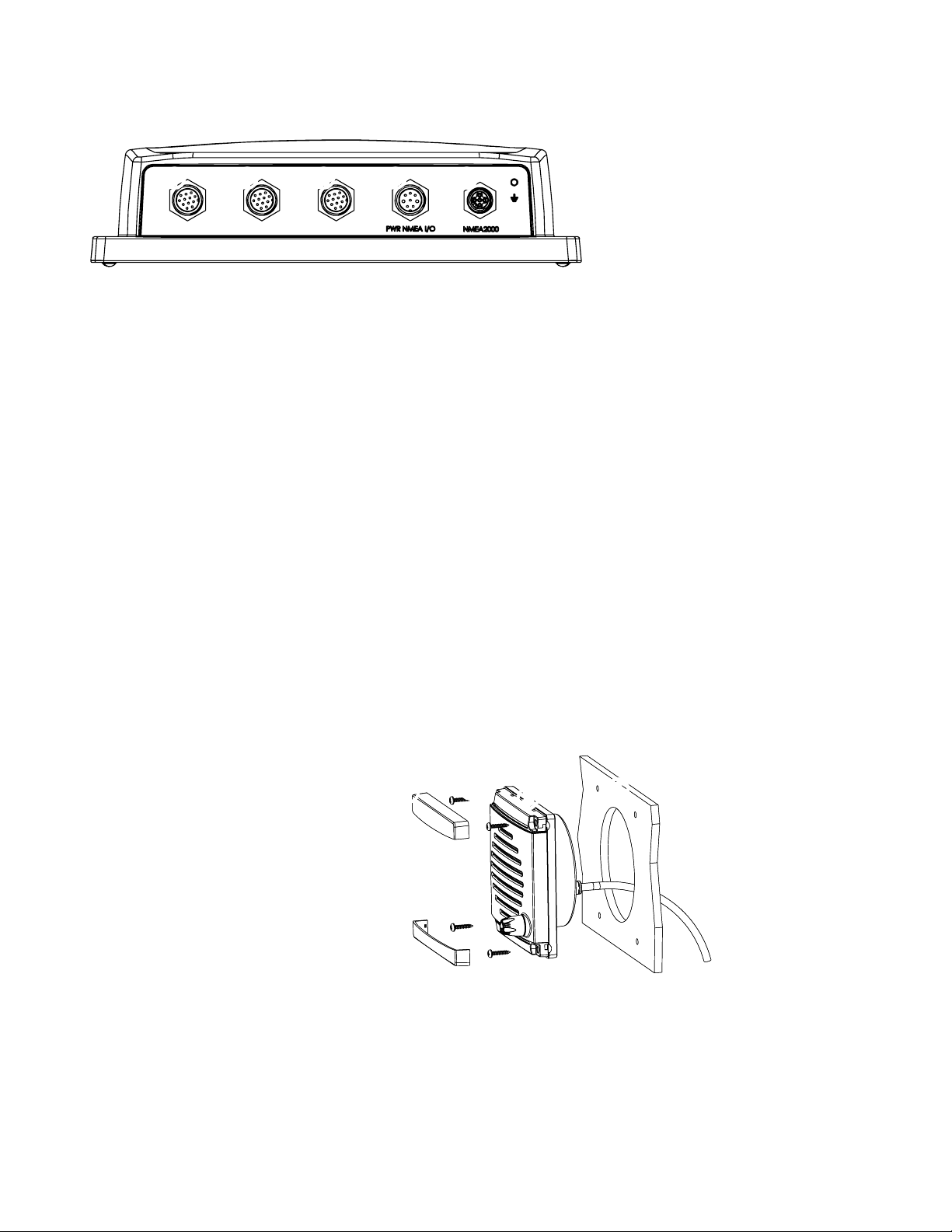
Identifying the VHF 300 Transceiver Box Connectors
Use the illustration to identify the connectors on the VHF 300 transceiver box.
➊
GHS 10 expansion connector
➋
HS-1—primary GHS 10 connector
➊ ➋ ➌➊ ➍
VHF 300 Transceiver Box Connectors
the wheelhouse GHS 10 must connect to
this port
➌
VHF 300 power/data cable connector
➍
NMEA 2000 connector (optional)
Antenna port (on back - not pictured)
Installing the GHS 10 and Speaker
The GHS 10 connects to the transceiver box and to either the Garmin GHS 10 active speaker (included) or a passive speaker (not included).
When planning the GHS 10 installation, consider the following:
Per FCC law, you must install the GHS 10 in the wheelhouse or an adjacent room.
•
Install the GHS 10 and the active speaker at least 20 in. (.5 m) from any compass.
•
Install the active speaker within 48 in. (1.2 m) of the location you mount the bulkhead pass-through plate.
•
Consult the VHF 300 Series Layout Diagram on page 2 to determine how to connect the GHS 10 through a bulkhead to a speaker and to the
•
transceiver box.
If the cable is not long enough to reach the GHS 10 mounting location from the transceiver box, extension cables are available in lengths of
•
16 ft. (5 m) and 32 ft. (10 m). Install any extensions between the GHS 10 cable and the transceiver box according to the layout diagram on
page 2.
When you install the GHS 10 active speaker, if you use the GHS 10 cable to connect the active speaker to the transceiver box, do not
•
connect a passive speaker to the GHS 10 cable. Clip and tape the passive speaker wires.
Installing the GHS 10 Active Speaker
1. Use the GHS 10 active speaker Flush Mount Template to mount the active speaker. The template is self-adhesive.
2. Remove the paper backing from the template and adhere it to the bulkhead in a suitable location.
3. Use a 3 1/2 in. (90 mm) hole saw to cut the opening as indicated on the template.
4. Place the speaker in the cutout.
5. Ensure that the mounting screw locations align with
➋
the holes marked on the template. If they do not,
mark the locations of new pilot holes.
6. Drill four 1/8 in. (3 mm) pilot holes* in the correct
location.
7. Use the included M4.2×25 screws to mount the
active speaker.
8. Snap the cover plates on the active speaker.
9. To install the active speaker wiring harness to the
transceiver box, use the GHC 10 cable according to
the layout diagram on page 2.
Do not connect a passive speaker to the GHC 10
•
cable you use with the active speaker. Clip and tape the two passive speaker wires.
If the GHC 10 cable is not long enough to reach the transceiver box location, install an extension (not included) between the GHC 10
•
cable and the transceiver box as shown on the layout diagram on page 2.
10. To install the active speaker wiring harness though the bulkhead, follow the procedures on page 5.
➊
➊
➋
➌
➌
Mounting the Active Speaker
Mounting the Active Speaker
➍
➍
➊
Cover plates (×2)
➊
Cover plates (×2)
➋
M4.2×25 screws (×4)
➋
M4.2×25 screws (×4)
➌
Active speaker
➌
Active speaker
➍
Bulkhead
➍
Bulkhead
* A 1/8 in. (3 mm) pilot hole is nominal for plywood. Different dashboard materials my require a different size pilot hole.
4 VHF 300 Series Installation Instructions
Page 5

Installing a Passive Speaker (Optional)
1. Follow the mounting instructions provided by the manufacturer of your passive speaker if it is not already mounted.
2. Consult the manufacturer of your passive speaker to identify the positive and negative speaker wires or terminals.
3. Use the GHS 10 Cable Wiring-Assignment Table to identify the positive and
negative wires.
4. Wire the correct positive and negative wires from the GHS 10 cable to the
passive speaker.
5. Use at least 22 AWG wire for extended runs of wire, if needed.
NOTICE: Cover the connections with a waterproof, adhesive tape, such as rubber vulcanizing tape, to prevent water from seeping into the radio.
Device Wire Color Function
Device Wire Color Function
GHS 10 cable Yellow Speaker positive (+)
GHS 10 cable Yellow Speaker positive (+)
Green Speaker negative (-)
Green Speaker negative (-)
GHS 10 Cable Wiring-Assignment Table
GHS 10 Cable Wiring-Assignment Table
Installing the Bulkhead Pass-Through Plate
1. Route the GHS 10 active speaker cable (or the GHS 10 cable) to the location you want to install the bulkhead pass-through plate.
2. Drill a 1 in. (25 mm) hole in the location at which you want to pass through the bulkhead.
3. Place the bulkhead pass-through plate over the hole and mark the three pilot-hole locations.
4. Drill the three 1/8 in. (3 mm) pilot holes.*
5. Connect the bulkhead pass-through plate to the bulkhead using the included M3.5 × 20 mm pan-head screws.
6. Remove the nut and connector cover from the GHS 10 cable (or the active speaker cable) and feed the connector through the bulkhead
pass-through plate.
7. Place the GHS 10 connector cover over the connector.
8. Use the nut to fasten the connector to the bulkhead pass-through plate.
➊
To the VHF 300 series transceiver box, or to the
active speaker (cable dependent)
➋
To a passive speaker (GHS 10 cable only)
➌
Bulkhead
➍
Bulkhead pass-through plate
➎
GHS 10 connector cover
➏
Nut
➐
M3.5 × 20 mm screws
➊
➋
➌
➍
➎
➏
➐
Installing the Bulkhead Pass-Through Plate
Mounting the GHS 10 Hanger
Using the GHS 10 hanger as a template, mark and drill
mounting screws to mount the hanger in a convenient location near the bulkhead pass-through plate.
1
/8 in. (3 mm) pilot holes.* Use three of the included 3.5 × 20 mm, panhead
Connecting the GHS 10
After you install the bulkhead pass-through plate and the GHS 10 hanger, connect the GHS 10 to the connector on the bulkhead pass through
plate. Hang the GHS 10 on the GHS 10 hanger.
Connecting the VHF 300 Series Radio to a Chartplotter (Optional)
You can connect the VHF 300 series radio to a chartplotter so that data such as DSC information can be displayed on the chartplotter.
Additionally, the radio can use location information from the GPS function of the chartplotter for position reports, and so forth.
You can connect the VHF 300 series radio to a NMEA 2000 network to access a NMEA 2000-compatible GPS antenna or chartplotter, or you
can wire the radio directly to a NMEA 0183-compliant chartplotter.
* A 1/8 in. (3 mm) pilot hole is nominal for plywood. Different dashboard materials my require a different size pilot hole.
VHF 300 Series Installation Instructions 5
Page 6

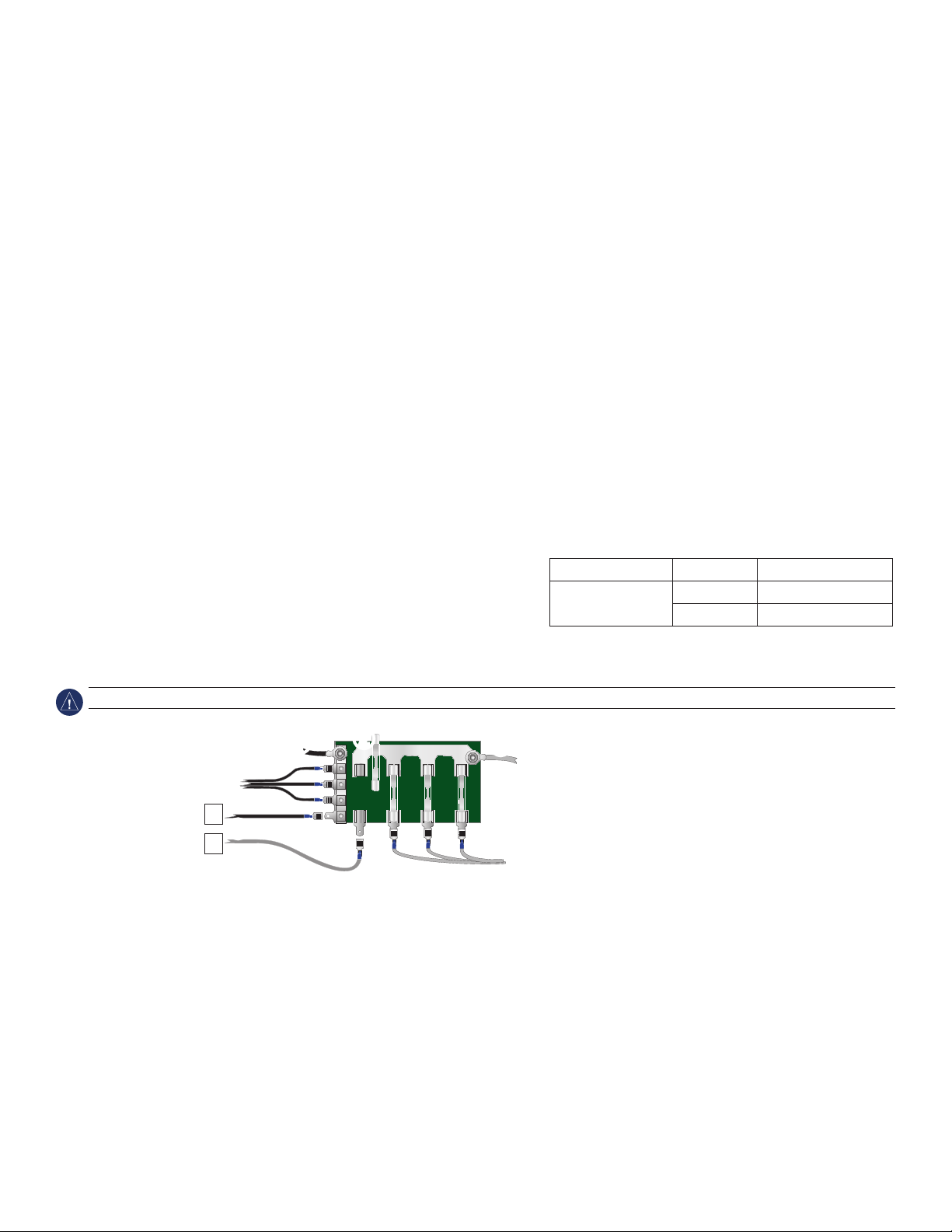
Connecting the VHF 300 Series Radio to a NMEA 2000 Network
+
-
You can connect the VHF 300 series radio to your existing NMEA 2000 network, or you can build a basic NMEA 2000 network to connect to
another NMEA 2000-compatible device, such as a chartplotter. For more information on NMEA 2000 and to purchase required connectors, go
to www.garmin.com.
To connect the VHF 300 series radio to your existing NMEA 2000 network:
1. Determine where you would like to connect the radio to your existing NMEA 2000 backbone.
2. Disconnect one side of a NMEA 2000 T-connector from the backbone at an appropriate location.
If you need to extend the NMEA 2000 backbone, connect an appropriate NMEA 2000 backbone extension cable to the side of the
T-connector you disconnected.
3. Add a T-connector (not included) for the radio to the NMEA 2000 backbone by connecting it to the side of the T-connector you disconnected.
4. Route a NMEA 2000 drop cable (not included) to the bottom of the T-connector added in step 3 to your NMEA 2000 network. Use a drop
cable with a length up to 20 ft. (6 m).
5. Connect the drop cable to the T-connector and the NMEA 2000 port on the VHF 300 Series transceiver box.
NOTICE: If you have an existing NMEA 2000 network on your boat, it should already be connected to power. Do not connect an additional NMEA
2000 power cable to an existing NMEA 2000 network, because only one power source should be connected to a NMEA 2000 network.
➊
➋
➌
➍
➎
Connecting the VHF 300 Series Radio to an
Existing NMEA 2000 Network
➊
VHF 300 series transceiver box
➋
NMEA 2000 device (not included)
➌
Drop cable (not included)
➍
T-connector (not included)
➋
➎
Existing NMEA 2000 network
➏
Ignition or in-line switch
➐
Fuse
➑
12 Vdc battery
➏
➐
➋
➑
➒
➓
Creating a Basic NMEA 2000 Network
➒
NMEA 2000 power cable (not included)
➓
Terminator (not included)
➊
➌
➍
➓
6 VHF 300 Series Installation Instructions
Page 7

To create a basic NMEA 2000 network:
+
-
>
>
>
>
>
>
>
>
1. Connect two T-connectors (not included) together by their sides.
2. Connect a NMEA 2000 power cable (not included) to one of the T-connectors.
NOTICE: A NMEA 2000 power cable must be connected to a 12 Vdc power source through a switch. The NMEA 2000 network may drain your
battery if it is connected directly. Connect the cable to the ignition switch of the boat if possible, or through an appropriate additional switch.
3. Connect a NMEA 2000 drop cable (not included) to the other T-connector and to the NMEA 2000 port on the VHF 300 Series transceiver
box.
4. Add additional T-connectors for each device you add to the NMEA 2000 network, and connect each device to a T-connector with a drop
cable.
5. Connect terminators (not included) to each end of the combined T-connectors.
Connecting the VHF 300 Series to a NMEA 0183 Device
The following diagram illustrates the NMEA 0183 wiring used to connect your VHF 300 series radio to a GPS chartplotter.
Connect NMEA 0183 bare wires as indicated in the following illustration. Use 22 AWG wire for extended runs of wire, if needed.
Battery
12 Vdc
Wire
Function
Power +
Ground -
Tx A (+)
Tx B (-)
Rx A (+)
Rx B (-)
NMEA 0183-
compatible
chartplotter
VHF 300
transceiver box
Wire Color
and Function
Fuse 10A
Connecting a VHF 300 Series Radio to a NMEA 0183 Device
Red—power (+)
Black—ground (-)
White—Rx A (+)
Orange/White—Rx B (-)
Gray—Tx A (+)
Pink—Tx B (-)
NOTICE: Cover the connections with a waterproof, adhesive tape, such as rubber vulcanizing tape, to prevent water from seeping into the radio.
Connecting the VHF 300 Series Radio to a Hailer Horn (Optional)
1. Follow the mounting instructions provided by the manufacturer of your hailer horn if it is not already mounted.
2. Consult the manufacturer of your hailer horn to identify the positive and
negative wires or terminals.
3. Use the VHF 300 Series Hailer-Horn Wiring Assignment Table to identify the
positive and negative wires.
4. Wire the correct positive and negative wires from the VHF 300 power/data
cable to the passive speaker.
5. Use 22 AWG wire for extended runs of wire, if needed.
Cable Wire Color Function
Cable Wire Color Function
VHF 300 power/
VHF 300 power/
data cable
data cable
VHF 300 Series Hailer-Horn Wiring-Assignment Table
VHF 300 Series Hailer-Horn Wiring-Assignment Table
Yellow Hailer-horn positive (+)
Yellow Hailer-horn positive (+)
Green Hailer-horn negative (-)
Green Hailer-horn negative (-)
NOTICE: Cover the connections with a waterproof, adhesive tape, such as rubber vulcanizing tape, to prevent water from seeping into the radio.
VHF 300 Series Installation Instructions 7
Page 8

Appendix
Specications
Transceiver Box
Dimensions: W × H × D: 9 3/4 × 7 3/32 × 2 1/2 in. (248 × 180 × 64 mm)
Weight: 4.177 lb. (1.895 kg)
Temperature Range:
Compass-safe Distance: 20 in. (.5 m)
Waterproof Rating: IEC 60529 IPX7 (Immersion in 1 meter of standing water for 30 minutes)
Operating Voltage:
Current Drain: 2 A max–6 A max (low power–high power transmit)
Antenna Connector: S0-239 (50 Ω)
Max Antenna Gain: 9 dBi
Antenna Port Impedance: 50 Ω
GHS 10
Dimensions: W × H × D: 6 11/32 × 2 13/16 × 1 11/16 in. (161 × 71.6 × 42.8 mm)
Weight: 12.98 oz. (368 g)
Temperature Range:
Compass-safe Distance: 20 in. (.5 m)
Waterproof Rating: IEC 60529 IPX7 (Immersion in 1 meter of standing water for 30 minutes)
from 14ºF to 122ºF (from -10ºC to 50ºC)
10.8–15.6 Vdc (12 Vdc boat battery)
from 14ºF to 122ºF (from -10ºC to 50ºC)
Active Speaker
Dimensions: W × H × D: 4 5/16 × 4 3/8 × 2 1/2 in. (109.7 × 111.4 × 63.5 mm)
Weight: 16.37 oz. (464 g)
Temperature Range:
Compass-safe Distance: 20 in. (.5 m)
Waterproof Rating: IEC 60529 IPX7 (Immersion in 1 meter of standing water for 30 minutes)
from 14ºF to 122ºF (from -10ºC to 50ºC)
Auxiliary Components
Hailer Output Power: 30 W max
Hailer Horn Impedance: 4 Ω
Passive Speaker Output Power:
Passive Speaker Impedance: 4 Ω
4 W (4 Ω max)
Cables
Power/data Cable: 78 in. (2 m)
GHS 10 cable: 32 ft. (10 m)
Active speaker cable (attached to the active speaker): 59 in. (1.5 m)
8 VHF 300 Series Installation Instructions
Page 9

Communications
0168
NMEA 2000
Use this table to determine the approved NMEA 2000 PGN information that can be received and transmitted by a VHF 300 series radio when
communicating with a NMEA 0183-compliant device.
Receive Transmit
059392 ISO Acknowledgment 059392 ISO Acknowledgment
059904 ISO Request 060928 ISO Address Claim
060928 ISO Address Claim 126208 NMEA Request/Command/Acknowledge Group Function
126208 NMEA - Command/Request/Acknowledge Group Function 126464 PGN List
129026 COG (course over ground) and SOG (speed over ground)
- Rapid Update
129029 GNSS (Global Navigation Satellite System) Position Data 129038* AIS Class A Position Report
129039* AIS Class B Position Report 129040* AIS Class B Extended Position Report
129794* AIS Class A Static and Voyage Related Data 129798* AIS SAR Aircraft Position Report
129808 DSC Call Information 129799 Radio Frequency/Mode/Power
Garmin VHF 300 Series radios are NMEA 2000 certied.
126996 Product Information
129799 Radio Frequency/Mode/Power
129808 DSC Call Information
NMEA 0183
The VHF 300 series radio can receive and transmit the following NMEA 0183 sentences (version 3.01) from a NMEA 0183-compliant device:
Sentence
(Receive)
GGA Global Positioning System Fix Data DSC DSC Information
GLL Geographic Position (Latitude and Longitude) DSE Expanded DSC
GNS GNSS (Global Navigation Satellite System) Fix
RMA Recommended Minimum Specic Loran-C Data
RMB Recommended Minimum Navigation Information
RMC Recommended Minimum Specic GNSS Data
Refer to the VHF 300 Series Owner’s Manual to operate the GHS 10 or GHS 10i handset.
The CE Notied Body number (0168) is valid for the VHF 300i and VHF 300i AIS only.
Denition Sentence
(Transmit)
VDM* AIS Information
Data
Denition
* VHF 300 AIS models only
VHF 300 Series Installation Instructions 9
Page 10

© 2010 Garmin Ltd. or its subsidiaries
Garmin International, Inc.
1200 East 151st Street,
Olathe, Kansas 66062, USA
Tel. (913) 397.8200 or (800) 800.1020
Fax (913) 397.8282
All rights reserved. Except as expressly provided herein, no part of this manual may be reproduced, copied, transmitted, disseminated, downloaded or stored in any storage
medium, for any purpose without the express prior written consent of Garmin. Garmin hereby grants permission to download a single copy of this manual onto a hard drive or
other electronic storage medium to be viewed and to print one copy of this manual or of any revision hereto, provided that such electronic or printed copy of this manual must
contain the complete text of this copyright notice and provided further that any unauthorized commercial distribution of this manual or any revision hereto is strictly prohibited.
Information in this document is subject to change without notice. Garmin reserves the right to change or improve its products and to make changes in the content without
obligation to notify any person or organization of such changes or improvements. Visit the Garmin Web site (www.garmin.com) for current updates and supplemental
information concerning the use and operation of this and other Garmin products.
Garmin® and the Garmin logo are trademarks of Garmin Ltd. or its subsidiaries, registered in the USA and other countries. GHS™ is a trademark of Garmin Ltd. or its
subsidiaries. These trademarks may not be used without the express permission of Garmin.
NMEA 2000® and the NMEA 2000 logo are registered trademarks of the National Maritime Electronics Association.
Garmin (Europe) Ltd.
Liberty House
Hounsdown Business Park,
Southampton, Hampshire, SO40 9LR UK
Tel. +44 (0) 870.8501241 (outside the UK)
0808 2380000 (within the UK)
Fax +44 (0) 870.8501251
Garmin Corporation
No. 68, Jangshu 2nd Road,
Sijhih, Taipei County, Taiwan
Tel. 886/2.2642.9199
Fax 886/2.2642.9099
10 VHF 300 Series Installation Instructions
Page 11

in.
16
/
1
9
(230 mm)
in.
8
/
1
5
(130 mm)
Page 12

For the latest free software updates (excluding map data) throughout the life of your
Garmin products, visit the Garmin Web site at www.garmin.com.
© 2010 Garmin Ltd. or its subsidiaries
Garmin International, Inc.
1200 East 151st Street, Olathe, Kansas 66062, USA
Garmin (Europe) Ltd.
Liberty House, Hounsdown Business Park, Southampton, Hampshire, SO40 9LR UK
Garmin Corporation
No. 68, Jangshu 2nd Road, Shijr, Taipei County, Taiwan
www.garmin.com
May 2010 Part Number 190-01098-02 Rev. C Printed in China
 Loading...