

Garland MP-ED-20-S Installation Manual

INSTALLATION AND
OPERATION MANUAL
FOR YOUR SAFETY:
DO NOT STORE OR USE GASOLINE
OR OTHER FLAMMABLE VAPORS OR
LIQUIDS IN THE VICINITY OF
THIS OR ANY OTHER
APPLIANCE
WARNING:
IMPROPER INSTALLATION, ADJUSTMENT,
ALTERATION, SERVICE OR MAINTENANCE
CAN CAUSE PROPERTY DAMAGE, INJURY,
OR DEATH. READ THE INSTALLATION,
OPERATING AND MAINTENANCE
INSTRUCTIONS THOROUGHLY
BEFORE INSTALLING OR
SERVICING THIS EQUIPMENT
AND RETAIN FOR FUTURE REFERENCE.
THIS PRODUCT HAS BEEN CERTIFIED AS
COMMERCIAL COOKING EQUIPMENT AND
MUST BE INSTALLED BY PROFESSIONAL
PERSONNEL AS SPECIFIED.
IN THE COMMONWEALTH OF MASSACHUSETTS
THIS PRODUCT MUST BE INSTALLED BY A
LICENSED PLUMBER OR GAS FITTER. APPROVAL
NUMBER: G-1-07-05-28
For Your Safety:
Post in a prominent location, instructions to be
followed in the event the user smells gas. This
information shall be obtained by consulting
your local gas supplier.
Users are cautioned that maintenance and repairs must be performed by a Garland authorized service agent
using genuine Garland replacement parts. Garland will have no obligation with respect to any product that has been
improperly installed, adjusted, operated or not maintained in accordance with national and local codes or installation
instructions provided with the product, or any product that has its serial number defaced, obliterated or removed,
or which has been modified or repaired using unauthorized parts or by unauthorized service agents.
For a list of authorized service agents, please refer to the Garland web site at http://www.garland-group.com.
The information contained herein, (including design and parts specifications), may be superseded and is subject
to change without notice.
PLEASE READ ALL SECTIONS OF THIS MANUAL
GARLAND COMMERCIAL INDUSTRIES
185 East South Street
Freeland, Pennsylvania 18224
Phone: (570) 636-1000
Fax: (570) 636-3903
Part # 1936601 Rev 6 (01/08) © 2005 Garland Commercial Industries, Inc.
GARLAND COMMERCIAL RANGES, LTD.
1177 Kamato Road, Mississauga, Ontario L4W 1X4
CANADA
Phone: 905-624-0260
Fax: 905-624-5669
Enodis UK LTD.
Swallow eld Way, Hayes, Middlesex UB3 1DQ ENGLAND
Telephone: 081-561-0433
Fax: 081-848-0041
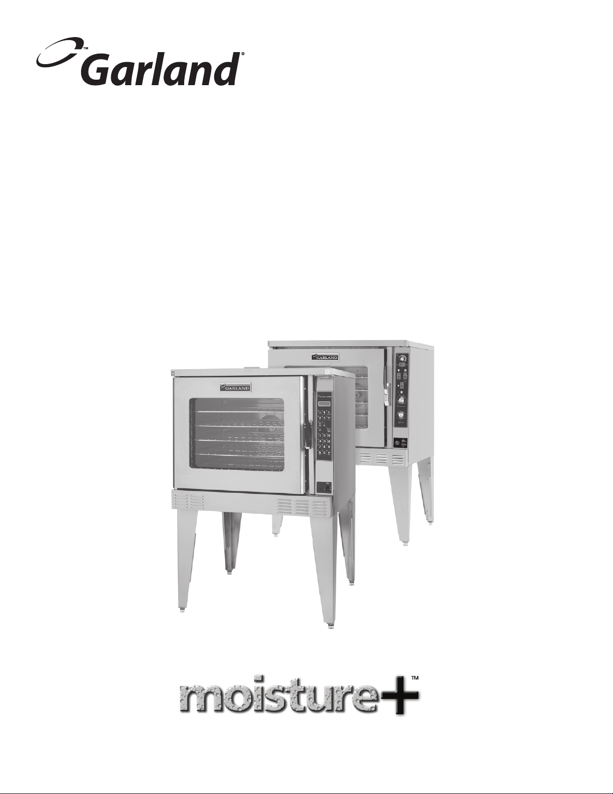
Congratulations! You have just purchased the latest in cooking technology, the new moisture+™ from Garland.
Garland is an established leader in innovative oven technology, and has manufactured this multifunction oven with the
operator in mind. The moisture+
™
provides function not previously available in a convection oven. Your moisture+™ will operate
as three pieces of equipment: a convection oven, a humidi ed baking oven, and a humidi ed cook & hold oven. Additionally,
the optional wet-clean water spray attachment allows you to easily spray down the oven interior during cleaning. Garland,
long known for o ering the “best baking” convection ovens available, adds the moisture+ to its model line to provide you, the
user with, a workhorse oven that will provide years of useful service.
Like any other ne, precision built appliance, your moisture+
™
oven should be given regular care and maintenance. Periodic
inspection by your dealer or a quali ed service agency is recommended. When corresponding with the factory or your local
authorized factory service center regarding service problems or replacement parts, be sure to refer to the particular oven by
the correct model number, (including the pre x/su x letters and numbers), and the warranty serial number. The rating plate
a xed to the oven contains this information.
Part # 1936601 Rev. 6 (01/08)Page 2

TABLE OF CONTENTS
DIMENSIONS AND SPECIFICATIONS . . . . . . . . . . . . . . .4
PREPARING THE OVEN FOR INSTALLATION . . . . . . . . 5
Legs and Casters . . . . . . . . . . . . . . . . . . . . . . . . . . . . . . . . . . . . .5
Open Base Assembly . . . . . . . . . . . . . . . . . . . . . . . . . . . . . . . . .6
Stacking Two Ovens. . . . . . . . . . . . . . . . . . . . . . . . . . . . . . . . . . 7
INSTALLATION . . . . . . . . . . . . . . . . . . . . . . . . . . . . . . . . . .8
Location . . . . . . . . . . . . . . . . . . . . . . . . . . . . . . . . . . . . . . . . . . . . .8
Wall Clearance . . . . . . . . . . . . . . . . . . . . . . . . . . . . . . . . . . . . . . .8
GAS CONNECTIONS . . . . . . . . . . . . . . . . . . . . . . . . . . . . . .8
ELECTRICAL CONNECTIONS . . . . . . . . . . . . . . . . . . . . . .9
WATER CONNECTIONS . . . . . . . . . . . . . . . . . . . . . . . . . .10
Water Quality Requirements. . . . . . . . . . . . . . . . . . . . . . . . 10
Spray/Flex Hose W/Quick Disconnect . . . . . . . . . . . . . . . 10
Drain . . . . . . . . . . . . . . . . . . . . . . . . . . . . . . . . . . . . . . . . . . . . . . 10
VENTILATION AND AIR SUPPLY . . . . . . . . . . . . . . . . . .11
INSTALLATION OF A DIRECT VENT . . . . . . . . . . . . . . .11
GAS MODEL TESTING & LIGHTING INSTRUCTIONS 12
To Conserve Energy: . . . . . . . . . . . . . . . . . . . . . . . . . . . . . . . 12
High Fan . . . . . . . . . . . . . . . . . . . . . . . . . . . . . . . . . . . . . . . . . . 16
Low Fan . . . . . . . . . . . . . . . . . . . . . . . . . . . . . . . . . . . . . . . . . . . 16
Pulse Fan . . . . . . . . . . . . . . . . . . . . . . . . . . . . . . . . . . . . . . . . . . 16
Cool Down. . . . . . . . . . . . . . . . . . . . . . . . . . . . . . . . . . . . . . . . . 16
Cook/Hold . . . . . . . . . . . . . . . . . . . . . . . . . . . . . . . . . . . . . . . . . 16
Start/Cancel . . . . . . . . . . . . . . . . . . . . . . . . . . . . . . . . . . . . . . . 16
Program . . . . . . . . . . . . . . . . . . . . . . . . . . . . . . . . . . . . . . . . . . . 16
Numeric Keys . . . . . . . . . . . . . . . . . . . . . . . . . . . . . . . . . . . . . . 16
“N”/Scroll . . . . . . . . . . . . . . . . . . . . . . . . . . . . . . . . . . . . . . . . . . 16
“Y”/Enter . . . . . . . . . . . . . . . . . . . . . . . . . . . . . . . . . . . . . . . . . . 16
OPERATING INSTRUCTIONS, (Deluxe Models) . . . . .17
Programmable Control (Deluxe Models) . . . . . . . . . . . . 17
Start-Up . . . . . . . . . . . . . . . . . . . . . . . . . . . . . . . . . . . . . . . . . . . 17
Auto Cool Down And Cool Down . . . . . . . . . . . . . . . . . . . 17
Start/Cancel . . . . . . . . . . . . . . . . . . . . . . . . . . . . . . . . . . . . . . . 17
Changing the Temperature Scale, (°F or °C). . . . . . . . . . 17
Basic Cook Cycle . . . . . . . . . . . . . . . . . . . . . . . . . . . . . . . . . . . 17
Using Cook & Hold . . . . . . . . . . . . . . . . . . . . . . . . . . . . . . . . . 18
Cooking With a Core Probe . . . . . . . . . . . . . . . . . . . . . . . . . 19
Programming Recipe Keys. . . . . . . . . . . . . . . . . . . . . . . . . . 20
System Program Options. . . . . . . . . . . . . . . . . . . . . . . . . . . 20
Cooking With a Recipe Key . . . . . . . . . . . . . . . . . . . . . . . . . 21
Using the Shelf Timer Feature . . . . . . . . . . . . . . . . . . . . . . 21
Display Messages . . . . . . . . . . . . . . . . . . . . . . . . . . . . . . . . . . 22
EXPLANATION OF CONTROLS (Standard Models) .13
Moisture Control. . . . . . . . . . . . . . . . . . . . . . . . . . . . . . . . . . . 13
Moisture Switch. . . . . . . . . . . . . . . . . . . . . . . . . . . . . . . . . . . . 13
Fan Speed Switch . . . . . . . . . . . . . . . . . . . . . . . . . . . . . . . . . . 13
Power Switch . . . . . . . . . . . . . . . . . . . . . . . . . . . . . . . . . . . . . . 13
Light Switch . . . . . . . . . . . . . . . . . . . . . . . . . . . . . . . . . . . . . . . 13
Temperature. . . . . . . . . . . . . . . . . . . . . . . . . . . . . . . . . . . . . . . 13
Timer . . . . . . . . . . . . . . . . . . . . . . . . . . . . . . . . . . . . . . . . . . . . . . 13
OPERATING INSTRUCTIONS, (Standard Models). . .14
In O Mode . . . . . . . . . . . . . . . . . . . . . . . . . . . . . . . . . . . . . . . . 14
Start Up . . . . . . . . . . . . . . . . . . . . . . . . . . . . . . . . . . . . . . . . . . . 14
Fan Speed . . . . . . . . . . . . . . . . . . . . . . . . . . . . . . . . . . . . . . . . . 14
Interior Light. . . . . . . . . . . . . . . . . . . . . . . . . . . . . . . . . . . . . . . 14
Cool Down. . . . . . . . . . . . . . . . . . . . . . . . . . . . . . . . . . . . . . . . . 14
Temperature . . . . . . . . . . . . . . . . . . . . . . . . . . . . . . . . . . . . . . 14
Timer . . . . . . . . . . . . . . . . . . . . . . . . . . . . . . . . . . . . . . . . . . . . . . 14
Moisture Control. . . . . . . . . . . . . . . . . . . . . . . . . . . . . . . . . . . 14
Moisture Switch. . . . . . . . . . . . . . . . . . . . . . . . . . . . . . . . . . . . 14
EXPLANATION OF CONTROLS, (Deluxe Models) . . .15
Display . . . . . . . . . . . . . . . . . . . . . . . . . . . . . . . . . . . . . . . . . . . . 15
On/O. . . . . . . . . . . . . . . . . . . . . . . . . . . . . . . . . . . . . . . . . . . . . 15
Light . . . . . . . . . . . . . . . . . . . . . . . . . . . . . . . . . . . . . . . . . . . . . . 15
Moisture. . . . . . . . . . . . . . . . . . . . . . . . . . . . . . . . . . . . . . . . . . . 15
COOKING WITH MOISTURE . . . . . . . . . . . . . . . . . . . . . .26
Mechanical Control, (Standard Models) . . . . . . . . . . . . . 26
Programmable Control, (Deluxe Models). . . . . . . . . . . . 26
User Moisture Settings . . . . . . . . . . . . . . . . . . . . . . . . . . . . . 26
Tips For Cooking With Moisture. . . . . . . . . . . . . . . . . . . . . 26
MOISTURE + COOKING GUIDE . . . . . . . . . . . . . . . . . . .27
PERFORMANCE RECOMMENDATIONS . . . . . . . . . . . .29
About Moisture Presets . . . . . . . . . . . . . . . . . . . . . . . . . . . . 29
TEMPERATURE CALIBRATION . . . . . . . . . . . . . . . . . . . .30
PROBLEMS / SOLUTIONS . . . . . . . . . . . . . . . . . . . . . . . .31
CLEANING . . . . . . . . . . . . . . . . . . . . . . . . . . . . . . . . . . . . .32
Break-In Period . . . . . . . . . . . . . . . . . . . . . . . . . . . . . . . . . . . . 32
Exterior Cleaning . . . . . . . . . . . . . . . . . . . . . . . . . . . . . . . . . . 32
Interior Cleaning . . . . . . . . . . . . . . . . . . . . . . . . . . . . . . . . . . . 32
Fan Area Cleaning . . . . . . . . . . . . . . . . . . . . . . . . . . . . . . . . . 32
MAINTENANCE . . . . . . . . . . . . . . . . . . . . . . . . . . . . . . . . .33
MOTOR CARE . . . . . . . . . . . . . . . . . . . . . . . . . . . . . . . . . . .33
WATER SYSTEM . . . . . . . . . . . . . . . . . . . . . . . . . . . . . . . . .33
REPLACEMENT PARTS . . . . . . . . . . . . . . . . . . . . . . . . . . .34
Part # 1936601 Rev. 6 (01/08) Page 3

DIMENSIONS AND SPECIFICATIONS
38"
[965mm]
2-1/4"
[57mm]
2-1/4"
[57mm]
32-3/4"
[832mm]
DOOR OPENING
REQUIRED
32"
[813mm]
58.5"
[1486mm]
26-1/2"
[673mm]
FLOOR
LINE
40" [1015mm]
ADD 4" [102mm]
FOR DEEP OVENS
32-3/4"
[832mm]
DOOR OPENING
REQUIRED
32"
[813mm]
32"
[813mm]
70-1/4"
[1784mm]
5-1/2"
[140mm]
6-1/4"
[159mm]
SINGLE DECK
GAS SUPPLY
3/4" NPT
1/8" NPT
WATER SUPPLY
DOUBLE STACK
GAS SUPPLY
1" NPT
15"
[381mm]
8-1/4"
[210mm]
10-1/2"
[267mm]
1-1/2" NPT
DRAIN CONNECTION
Notes:
1. Standard electrical
specications include motor
requirements.
2. All ovens have a ¾ HP, two
speed motor; 1140 and 1725
RPM, 60 Hz.
3. Garland recommends that a
separate 15 Amp circuit be
provided for each 120V oven
4. A 6 foot line cord is provided for
each 120V oven with a NEMA
5-15P plug.
5. Double stack installations
require an individual power
supply connection to each
oven.
Gas input ratings are for
installations up to 2000 feet
(610 m) above sea level. Specify
altitudes above 2000 feet.
Models
Natural ¾” NPT 80,000 23.5
Propane ¾” NPT 60,000 17.6
Electric
Models
MP-ES/GS-10-S
MP-ES/GS-20-S
MP-ED/GD-10-S
MP-ED/GD-20-S
Gas
Input Ratings
Gas
Inlet
BTU
Hour
Input Ratings Nominal Amperes
Total KW/Line
kW
208/240/460
X-Y Y-Z X-Z X/Y/Z X/Y/Z X/Y/Z
11 3.33 3.33 4.33 N/A 53 46 24 31.8/27.7/31.8 27.6/24.0/27.6 10.5/9.5/10.5
Model Description
Std Depth,
Sgl Deck
Std Depth,
Dbl Deck
Deep Depth,
Sgl Deck
Deep Depth,
Dbl Deck
kW
120V
208V
1Ph
1 Ph
Interior Dimensions: in [mm] Exterior Dimensions: in [mm]
W H D W H D
29 [736] 24 [610]
240 V
1 Ph
460V
1 ph
208V 3 Ph 240V 3 Ph 460V 3 Ph
24 [610]
38 [965]
28 [711]
60-3/4 [1543]
72-1/2 [1842] 1024/464 84
60-3/4 [1543]
72-1/2 [1842] 1024/464 84
Commercial cooking equipment
requires an adequate ventilation
system. For additional information
refer to the National Fire Protection
Associations standard NFPA96,
“Vapors Removal from Cooking
Equipment” (Note: For North
America only)
Weight
(lbs/kg)
510/232 42
40 [1016]
510/232 42
44 [1118]
Size
(Cu ft)
Part # 1936601 Rev. 6 (01/08)Page 4

PREPARING THE OVEN FOR INSTALLATION
Figure 1.
CASTER INSERT (4)
CASTER (4)
SCREW (2 PER CASTER INSERT)
FLAT WASHER (4 EACH LEG)
BOLT (4 EACH LEG)
FOOT INSERT (4)
LEG ASSEMBLY (4)
BOLT (4 EACH CASTER)
FLAT WASHER (4 EACH CASTER)
DOUBLE DECK CASTER (4)
Legs and Casters
NOTE: If you will be installing an open base kit, please skip to
the next page and proceed with the steps listed under “Open
Base Assembly.”
1. (See Figure 1.). At the bottom end of each leg, install the
bullet foot insert or caster insert. The t of the insert to the
leg is intended to be snug, tap them lightly into place with
a mallet or rubber hammer.
Install two #5 x 1/4” self-drilling, thread forming screws
into each caster insert.
2. Screw a caster into the insert on each of the four legs.
The caster must be inserted at least three full threads to
properly support the oven. A 1” (25mm) open-end wrench
may be needed to properly install the casters.
OR
Using your ngers, screw the ends of the bullet feet into
the leg clockwise until they are at their shortest length.
3. Carefully tip and lower the oven onto its left side so you
can easily reach the bolt mounting locations in the base.
4. The four holes in the top of each leg or in the top plate of
double stack casters will match the bolt locations at each
corner of the oven base.
You will need four 3/8-16 x 1” hex head bolts and four 3/8”
at washers to mount each leg. Align the leg to one of the
matching bolt holes on the base and insert a bolt with
washer.
Install the remaining three bolts and nger-tighten all
four before using an 11/16” wrench to fully tighten them
all. Be sure to tighten all four bolts for each leg or caster.
When installing casters, make sure the two casters with
brakes are installed at the front of the oven.
5. Carefully return the oven to an upright position. Ensure
the two legs/casters that touch the oor rst when you
raise the oven are blocked and chocked so they do not slip
away.
6. It is very important to use the adjustable bullet foot
inserts in leveling the unit.
7. If you have installed casters, be sure to install the restraint
bracket on the lower left corner of the rear of the oven
using two #10 x 3/4” sheet metal screws.
Part # 1936601 Rev. 6 (01/08) Page 5

PREPARING THE OVEN FOR INSTALLATION
Figure 2.
RACK GUIDE UPPER SUPPORT
RACK GUIDE (2)
INNER GUIDE POSITION
FOR TRAYS
OUTER GUIDE POSITION
FOR RACKS
OPEN BASE PANEL
SCREW (6x)
LEG ASSEMBLY (4)
W/FOOT INSERT
OPEN BASE UPPORT CLIP (4)
SCREW (1 EACH CLIP)
SCRREW (2 EACH CLIP)
INNER
OU
T
ER
Open Base Assembly
Use the following sequence of steps to assemble and install
the open base accessory.
1. (See Figure 2.). Align the rack guide upper support to the
corresponding holes in the oven base. Fasten using three
#10 x 3/4” machine screws on each side of the oven.
2. At the lower end of each leg install an “L” shaped support
clip using a #10 x 3/4” sheet metal screw. Do this before
fastening the leg to the base.
3. Install legs to the bolt holes at the front and rear of the
base on the oven’s left side, (side lying on the oor). If
installing casters, be sure to install a locking caster on the
front leg. Refer to the section, “Legs and Casters,” on the
previous page for installation details.
4. Fasten the open base panel in place on the brackets of
the two legs already installed, using one #10 x 3/4” sheet
metal screw in each corner.
5. While supporting the open base panel, install the rightside legs as in step 2. Ensure the caster with a brake is at
the front of the oven. Fasten the remaining two corners of
the open base panel to the other two legs just installed.
6. Carefully return the oven to an upright position. Ensure
the two legs/casters that touch the oor rst when you
raise the oven are blocked and chocked so they do not slip
away.
7. Install the rack guides in one of the two available
positions. The inner position sets the guides at a width
to accommodate oven pans. The outer position sets the
guides at a width to accommodate wire oven racks. To
attach, insert the longer straight end at the top of the rack
guide all the way into the mounting hole, then align the
bottom holes and lower the rack guide into position.
8. It is very important to use the adjustable bullet foot
inserts in leveling the unit.
9. If you have installed casters, be sure to install the restraint
bracket on the lower left corner of the rear of the oven
using two #10 x 3/4” sheet metal screws.
Part # 1936601 Rev. 6 (01/08)Page 6

PREPARING THE OVEN FOR INSTALLATION
7
9
3
2
1
14
13
11
8
12
5
12
4
9
13
Stacking Two Ovens
1. Follow the instructions in the section entitled, “Legs and
Casters,” on page 5. Then resume at step 2 on this page to
complete the stacking process.
2. Move the lower oven as close to the nal installation point
as possible, leaving enough space around the oven to
allow access for the remaining installation steps. If casters
have been installed, apply the brakes on the two front
wheels.
3. Carefully raise the upper oven and place it on top of the
lower oven, aligning the four lower corners of the upper
even to the four upper corners of the lower oven.
4. At the rear of the stacked ovens, install the stacking
bracket using six 1/4-20 x 1” hex head bolts with lock
washers and nuts. Firmly tighten all six nuts/bolts to
secure the ovens together.
5. Remove the outer ue vent from the right top corner of
the rear of each oven, saving the screws.
6. If they are not already fastened together, assemble the
two parts of the interconnecting ue channel included in
the stacking kit, using six #10 x 3/4” sheet metal screws.
7. Fit the channel assembly over the ue vent area of each
oven and fasten using the screws removed in step 5.
8. If you have installed casters, be sure to install the restraint
bracket on the lower left corner of the rear of the upper
oven using two #10 x 3/4” sheet metal screws.
9. If your installation requires one common gas inlet for both
ovens, use the piping included with your stacking kit to
assemble the interconnecting gas pipe. Refer to Figure 3.
NOTE: It is recommended, when stacking a Moisture + Oven
with a Master Convention Oven, that the Moisture + be
located on the bottom.
Item Reference Key For Figure 3
Item
No.
Item Description
1 MSCR-HH STL 1/4-20x3/4
2 LKSHR-SPL 1/4x1/2x1/6
3 Nut - Hex 1/4-20 STL ZP
4 Bell Reducer 1” x 3/4”
5 3/4 Tee NPT
7 Flue Assembly – Double Stack
8 Pipe Union 3/4 NPT
10 Close Nipple 3/4 x 1
11 Pipe 3/4 x 20-1/2”
12 3/4 x 3-1/2 Nipple
13 Bell Reducer
14 Stacking Bracket Rear
Figure 3.
Part # 1936601 Rev. 6 (01/08) Page 7

INSTALLATION
It is the responsibility of the purchaser to ensure the oven is
installed in a manner to meet all local codes. In the absence
of local codes, applicable national codes are referenced in this
booklet. In the case of discrepancy between the information
in this booklet and local codes, it is recommended you
consult your local inspector(s). This appliance meets or
exceeds all applicable regulations and standards in eect on
its date of manufacture.
Location
The importance of the proper installation of Commercial
Gas Cooking Equipment cannot be over stressed. Proper
performance of the equipment is dependent, in great part,
on the compliance of the installation with the manufacturer’s
specications. Installation must conform to local codes or, in
the absence of local codes, with the National Fuel Code, ANSI
Z223.1, Natural Gas Installation Code, CAN/CGA-B149.1, or the
Propane Installation Code, CAN/CGA-B149.2, as applicable.
GAS CONNECTIONS
The type of gas for which the oven is equipped is stamped on
the data rating plate. It is located inside the lower front trim
cover. Connect an oven stamped “NAT” to natural gas only.
Connect an oven stamped “PRO” to propane gas only.
If the oven is being installed into a new location, have gas
authorities check the meter size and piping to assure the supply
line has a sucient amount of gas pressure to operate the oven.
If the oven is a replacement or additional appliance to an
existing installation have gas authorities check the pressure
to ensure the existing meter and pressure will supply the
oven with no more than a 1/2” water column pressure drop.
Note: When checking the gas pressure make sure all other
appliances on the same gas line are turned on.
A pressure regulator is supplied with Garland convection
ovens. The regulator pressure is preset to deliver the gas
at the pressure shown on the rating plate. Do not install
an additional regulator where the unit connects to the
gas supply unless the gas pressure exceeds the maximum
recommended pressure.
The oven and its individual shut-o valve must be
disconnected from the gas supply piping system during any
pressure testing of that system at test pressures in excess of
1/2 PSI (3.45 kPa).
The oven must be isolated from the gas supply piping system
by closing its individual manual shut-o valve during any
pressure testing of the supply system at test pressures equal
to or less than 1/2 PSI (3.45 kPa).
Wall Clearance
This oven, single or stacked, must be installed with adequate
clearance to combustible and non-combustible walls.
Sides: 1 inch [25 mm]
Back: 3 inches [76 mm] for gas ovens, and
6 inches [152 mm] for electric ovens.
Garland recommends that a one inch clearance be
maintained between this oven and any other cooking
appliance.
Garland recommends that this oven not be installed with a
broiler or open burner appliance immediately adjacent to the
right side.
Each appliance shall be located with respect to building
construction and other equipment so as to permit access to
the appliance. Such access and clearance may be necessary
for servicing and cleaning.
Prior to connecting to the building gas supply the lines
should be purged of all metal lings, pipe thread compound
or other debris.
The gas connection piping (3/4” for single ovens, 1” for
stacked ovens), must be considered when planning the
supply line. Undersized gas supply lines may restrict the
gas ow and aect performance. If other gas appliances are
supplied by the same supply line, it must be sized to carry
the combined volume required for all the appliances without
causing a more than 1/2” pressure drop at the manifold of
each appliance on line at full rate.
Recommended supply pressures are 7” ± 5% WC for natural
gas (NAT) and 11” ± 5% WC for propane (PRO). The inlet
pressure for the supply line must not exceed 13.8” WC natural
and 15”WC for propane.
Two ovens stacked may be supplied by a single gas line. The
minimum recommended size of a single supply line for two
stacked ovens is 1 inch.
Assemble the gas pipes and ttings provided in the stacking
kit as shown in the Figure 3 on page 7. Use a pipe thread
compound that is intended for use on propane gas piping.
Be sure to check for leaks before nalizing the installation. Use
appropriate solutions or detection devices.
Installations in which a exible gas connection hose is
used, require the supplied strain relief to be installed at the
lower left rear corner of the base. Install the strain relief in
accordance with applicable codes. The strain relief must limit
the movement of the oven to prevent unnecessary stress on
the exible connector.
Part # 1936601 Rev. 6 (01/08)Page 8

ELECTRICAL CONNECTIONS
ELECTRIC OVENS - SHIPPED WITH KNOCKOUT
PLATE FOR POWER SUPPLY
REMOVE THIS SCREW TO ALLOW
ACCESS TO THE TERMINAL BLOCK (ELECTRIC OVENS)
OR CORD CONNECTIONS (GAS OVENS)
A separate electrical connection must be supplied for each
oven. Connection to the electrical service must be grounded
in accordance with local codes, or in the absence of local
codes with the National Electrical Code, ANSI/NFPA 70, or the
Canadian Electrical Code, CSA C22.2, as applicable.
A strain relief for the power supply cord is required. The
installer must supply a cord bushing that meets local and
national codes.
For 120VAC usage a cord and NEMA 5-15P plug is provided.
Garland recommends a separate 15 Amp service for each
oven. Ovens for 120V service are supplied with a three
pronged plug for your protection against shock hazard and
should be plugged directly into a properly grounded threeprong receptacle.
DO NOT CUT OR REMOVE THE GROUNDING PRONG FROM
THE PLUG.
A wiring diagram is axed to the rear of the oven and
included in this booklet.
CAUTION:
DISCONNECT ALL OVENS FROM ELECTRI-
CAL SUPPLY BEFORE
SERVICING.
POWER FAILURE:
IN THE EVENT OF A POWER
FAILURE, NO ATTEMPT SHOULD BE MADE
TO OPERATE THIS OVEN.
Figure 4.
Part # 1936601 Rev. 6 (01/08) Page 9

WATER CONNECTIONS
B
A
A
B
1/8" NPT WATER
SUPPLY CONNECTION
DETAIL A
1-1/2" NPT MALE
TRAP ADAPTER
DETAIL B
It is the responsibility of the purchaser to install and maintain
the water supply to the moisture+ oven. Failure to provide
satisfactory water quality to operate the oven properly
can cause damage to integral components and void your
warranty.
This oven must be installed to comply with the applicable
federal, state, or local plumbing codes.
Water supply connection to the moisture+ is made via a
1/8” NPTF tting at the rear of the oven. The ability to move
the oven for service and cleaning may be a consideration
when choosing the type of connection and supply line to be
attached at this tting.
The moisture+ water delivery system includes a water
pressure regulator that has been pre-set to operate at 20 psi.
The water supply must maintain at least 20 psi and a ow rate
of three gallons per minute for proper operation of the oven’s
moisture injection system.
Water Quality Requirements
Garland recommends that the supply water be ltered before
it enters the oven’s water delivery system. This will extend the
life of the oven and its water delivery system components by
minimizing particles in typical tap water sources that cause
scaling and build-up of mineral deposits.
The recommended minimum water quality standards,
whether treated or pre-treated, and based on 10 hours of use
per day, and daily cleaning./descaleing are as follows:
Total dissolved solids – less than 60 parts per million, total
alkalinity – less than 20 parts per million, silica – less than 13
parts per million, chlorine – less than 30 parts per million and
a pH Factor greater than 7.5.
Consult a local water treatment specialist for an on-site
water analysis for recommendations concerning feed water
treatment (if required), in order to remove or reduce harmful
concentrations of minerals. The use of highly mineralized
water will cause more frequent cleaning and reduce
operating eciency. The fact that a water supply is potable is
not proof that it will be suitable for moisture mode operation.
Component failure/service related to poor water quality will
not be covered under warranty.
Spray/Flex Hose W/Quick Disconnect
Your moisture+ oven may be equipped with the optional
spray/ex hose assembly. The spray/ex hose assembly is
intended to assist in cleaning the oven. The water pressure
and velocity may vary, depending on the pressure and
velocity of the water supply connected to the oven.
Drain
Your moisture+ oven has a gravity drain in the right rear
corner of the oven cavity. The drain pipe that exits the rear
of the oven must be directed downward toward the oor,
and should run directly to an open oor drain. Garland
provides an 1-1/2” male pipe adapter for connecting your
drain lines. Avoid using exible hose that could sag or kink,
allowing water to accumulate. The drain must be vented. This
connection must be at least 1-1/2” (38.1 mm) in diameter and
congured in accordance with local codes.
Figure 5.
Part # 1936601 Rev. 6 (01/08)Page 10
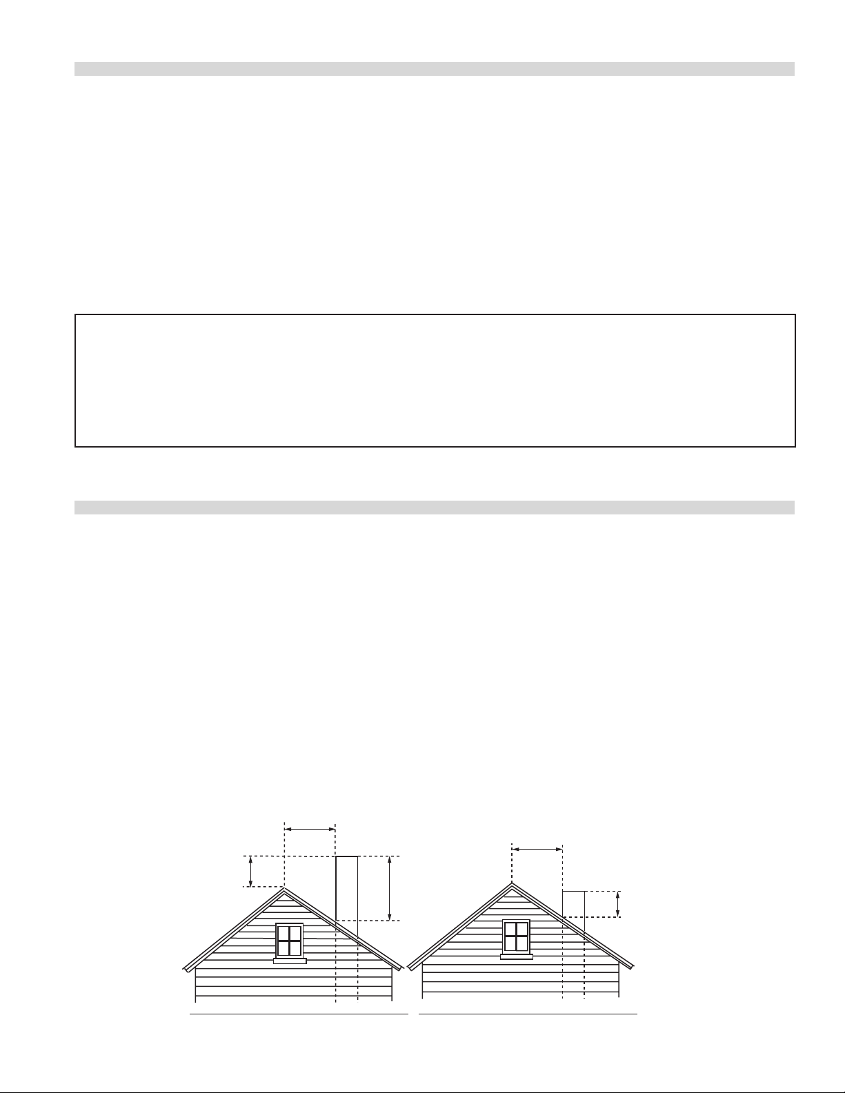
VENTILATION AND AIR SUPPLY
Termination Less than 10 feet (3 meters) from ridge Termination More than 10 feet (3 meters) from ridge
Less than 10 feet (3 meters)
More than 10' (3 meters)
2' (60cm) Min.
3' (90cm) Min.
3' (90cm) Min.
Figure 6.
Proper ventilation is highly important for eective operation.
There are only two choices for properly venting an oven:
1) canopy hood, or, 2) direct venting. The ideal method of
venting a gas oven is through the use of a properly designed
canopy hood. The hood should extend beyond all sides of the
oven 6 inches, (150 mm), and be installed at least 78 inches,
(1950mm), from the oor.
A strong exhaust fan will create a vacuum in the room. For
exhaust system vents to work properly, exhaust and make-up
air must be balanced. For proper air balance, contact your
local H.V.A.C. contractor.
IMPORTANT
ALL GAS BURNERS AND PILOTS NEED SUFFICIENT AIR TO OPERATE AND LARGE
OBJECTS SHOULD NOT BE PLACED IN FRONT OF THIS OVEN, WHICH COULD
OBSTRUCT THE AIRFLOW THROUGH THE FRONT. OBJECTS SHOULD NOT BE PLACED
ON MAIN TOP REAR OF THE OVEN WHILE IN USE. THIS COULD OBSTRUCT THE
VENTING SYSTEM OF THE OVEN’S FLUE PRODUCTS.
INSTALLATION OF A DIRECT VENT
All gas burners and pilots need sucient air to operate
and large objects should not be placed in the rear or at
the bottom of this oven which would obstruct the airow
through the front covers. Do not place objects over the oven
vent exit.
Some localities require an electric oven to be installed under
an exhaust hood. Be sure to consult your local code inspector
prior to operating any gas or electric oven.
When the installation of a canopy hood is impossible, the
oven may be direct vented. Before direct venting check you
local codes on ventilation, in the absence of local codes
refer to the National Fuel Code NFPA 54, ANSI Z223.1 (latest
revision).
If the oven is to be connected to a direct ue vent, it is
necessary that a draft diverter be installed to ensure proper
ventilation.
The draft diverter should be positioned on the main top of
the oven and fastened with sheet metal screws provided. All
parts described above are available from the manufacturer.
Note: Each oven has been factory tested and adjusted
prior to shipment. It may be necessary to further adjust the
oven as part of a proper installation. Such adjustments are
the responsibility of the installer. Adjustments cannot be
considered defects in material or workmanship and they are
not covered under the original equipment warranty.
DO NOT UNDERSIZE THE VENT PIPE! This can cause resistance
to ow and impede good venting. We suggest that if a
horizontal run must be used it should rise no less than 1/4”
(6.25mm) for each linear foot of run, and after a total of 180°
of bends you should increase the size of stove pipe by 2”. The
ue should rise 2’ (60 cm) to 3’ (90 cm) above the rooine or
2’ (60cm) to 3’ (90cm) above any portion of a building within a
horizontal distance of 10’ (3 m).
Part # 1936601 Rev. 6 (01/08) Page 11
 Loading...