

Page 1
INSTALLATION AND
OPERATION MANUAL
Models:
GARLAND INDUCTION
MODULE-LINE COOKTOPS
DUAL/QUAD
with RTCSmp TECHNOLOGY
Real-time Temperature Control System
multi-point sensing
CE models comply with the latest European
Norms:
EN 60335-1, EN 60335-2-36, EN 62233 (EMC/EMV)
North American models: ETL recognized* in
compliance with UL 197, CSA C22.2 No.109, NSF-4
Complies with FCC part 18, ICES-001
*Recognized components system, refer to section 4.1.
FOR YOUR SAFETY
DO NOT STORE OR USE GASOLINE OR OTHER
FLAMMABLE VAPORS OR LIQUIDS IN THE VICINITY
OF THIS OR ANY OTHER APPLIANC
Users are cautioned that maintenance and repairs must be performed by a Garland authorized service agent using only
genuine Garland replacement parts. Garland will have no obligation with respect to any product that has been improperly
installed, adjusted, operated or not maintained in accordance with national and local codes and/or installation instructions
provided with the product or any product that has its serial number defaced, obliterated or removed, and/or which has been
modified or repaired using unauthorized parts or by unauthorized service agents. For a list of authorized service agents and/or
genuine replacement parts, please visit our website at www.garland-group.com for USA and Canada. For international
customers, please visit www.manitowocfoodservice.com. The information contained herein, including design and part
specifications, may be superseded and is subject to change without notice.
MO DU 7000
MO DU 7000 FL
MO DU 10000
MO DU 14000 FL
PLEASE READ ALL SECTIONS OF THIS MANUAL AND
RETAIN FOR FUTURE REFERENCE.
THIS PRODUCT HAS BEEN CERTIFIED AS COMMERCIAL
COOKING EQUIPMENT AND MUST BE INSTALLED BY
PROFESSIONAL PERSONNEL AS SPECIFIED
INSTALLATION AND ELECTRICAL CONNECTION MUST
COMPLY WITH CURRENT CODES:
IN CANADA – THE CANADIAN ELECTRICAL CODE PART
1 AND / OR LOCAL CODES.
IN USA – THE NATIONAL ELECTRICAL CODE ANSI /
NFPA – CURRENT EDITION.
WARNING
IMPROPER INSTALLATION, ADJUSTMENT, ALTERATION,
SERVICE OR MAINTENANCE CAN CAUSE PROPERTY
DAMAGE, INJURY, OR DEATH. READ THE INSTALLATION,
OPERATING AND MAINTENANCE INSTRUCTIONS
THOROUGHLY BEFORE INSTALLING OR SERVICING THIS
EQUIPMENT
MO QU 14000
MO QU 20000
MO QU 21000
MO QU 24000
MO QU 28000 FL
Visit our Video Gallery at
Part # 4532415 Rev 3 (8/19/14) © 2013 Garland Commercial Ranges Limited
www.Garland-Group.com
Page 2
Installation and Operation Manual RTCSmp Built-In Module-Line Dual/Quad Cooktops
T
WARRANTY
Our warranty statements for induction products are available on-line. Please visit our
website at www.garland-group.com/minisite/service to download the latest revision.
UNPACKING and PACKING SLIP
The packing slip attached to the shipment contains detailed information on all
components. Please retain this packing slip for future reference.
USING THIS MANUAL
This manual contains important information regarding safety, installation, operation,
maintenance, and troubleshooting. They must be read entirely and carefully by the
installers and operators before the equipment is installed and taken into operation. This
manual must always be available for reference at the place of operation.
Throughout this manual, the induction unit type “RTCSmp Built-In Module Line” is referred
to as “induction unit”.
DESCRIPTION OF WARNING SYMBOLS
CAUTION
This symbol alerts you to a hazardous situation that WILL or COULD
cause serious bodily harm or death. Be alert and implement relevant
safety precautions.
This dangerous voltage warning symbol indicates a risk of electric shock
and hazards from dangerous voltage.
his symbol alerts a hazardous situation, which if not avoided, COULD
cause minor to moderate personal injury or property damage. The
relevant safety precautions MUST be implemented at all times.
Electromagnetic field.
Risk of fire or electric shock
To reduce the risk of fire or electric shock,
do not remove or open cover.
No user serviceable parts inside.
Refer servicing to qualified personnel.
Warning
Do not open
CONTACTS
Garland Commercial Ranges Ltd. | 1177 Kamato Road, Mississauga, Ontario, Canada. L4W 1X4
T: 1-905-624-0260 | F: 1-905-624-5669 | www.garland-group.com
USA Sales, Parts and Service 1-800-424-2411
Canadian Sales 1-888-442-7526
Canada or USA Parts/Service 1-800-427-6668
International Sales and Service www.ManitowocFoodservice.com
2 Part # 4532415 Rev 3 (8/19/14)
Page 3

Table of Contents RTCSmp Built-In Module-Line Dual/Quad Cooktops
1 Safety Requirements ................................................................................................................................................. 5
1.1 Important Electrical & Installation Requirements ......................................................................................................................... 5
1.2 Risk Involved By Disregarding Safety Information ....................................................................................................................... 5
1.3 Safety Instructions for Operator .......................................................................................................................................................... 5
1.4 Improper Use of the Equipment ......................................................................................................................................................... 6
1.5 Unauthorized Modification and Use of Spare Parts ..................................................................................................................... 6
1.6 Pan Detection ............................................................................................................................................................................................ 7
1.7 Cooking Zone Monitoring ..................................................................................................................................................................... 7
2 Components and Features ........................................................................................................................................ 8
2.1 Application .................................................................................................................................................................................................. 8
2.2 Components and Features .................................................................................................................................................................... 8
3 Dimensions and Technical Specifications .............................................................................................................. 10
3.1 Rating Plate ...............................................................................................................................................................................................10
3.2 Nomenclature and Models..................................................................................................................................................................10
3.3 Dimensions ...............................................................................................................................................................................................10
3.4 Models and Components Charts ......................................................................................................................................................10
3.5 Electrical Specifications ........................................................................................................................................................................11
3.6 Operating Conditions ...........................................................................................................................................................................12
3.7 Compliances .............................................................................................................................................................................................12
4 Installation ............................................................................................................................................................... 13
4.1 Important Safety & Electrical Requirements .................................................................................................................................13
4.2 Installation Overview and Installation Clearance .......................................................................................................................13
4.2.1 Installation Overview .......................................................................................................................................................13
4.2.2 Installation Clearance ......................................................................................................................................................15
4.3 Induction Generator ..............................................................................................................................................................................15
4.3.1 Location ................................................................................................................................................................................16
4.3.2 Ventilation ...........................................................................................................................................................................16
4.3.3 Dimensions ..........................................................................................................................................................................16
4.4 Control Unit and Operation Unit (Power Switches) ...................................................................................................................17
4.4.1 Location ................................................................................................................................................................................17
4.4.2 Ventilation ...........................................................................................................................................................................17
4.4.3 Mounting Methods ...........................................................................................................................................................18
4.4.4 Dimensions – Control Unit ............................................................................................................................................18
4.4.5 Dimensions Guide (Holes/Studs) .................................................................................................................................19
4.5 Coil Carrier Sheet, Ceran Glass and Mounting Frame ...............................................................................................................20
4.5.1 Location & Ventilation Requirements for Coil Carrier Sheet Installation ......................................................20
4.5.2 Countertop Cut-outs Dimensions ...............................................................................................................................20
4.5.3 Correct Orientation – Coil Carrier, Glass and Frame .............................................................................................20
4.5.4 Mounting Frames ..............................................................................................................................................................21
4.5.5 Installation Steps ...............................................................................................................................................................25
4.5.6 Custom-Built Mounting Frame ....................................................................................................................................28
4.6 Models, Components and Cable Connections ............................................................................................................................30
4.6.1 CHART 1 – Module-Line Round Coil Dual Models .................................................................................................30
4.6.2 CHART 2 – Module-Line Round Coil Quad Models ...............................................................................................31
4.6.3 CHART 3 – Module-Line Full Coil Dual Models .......................................................................................................32
4.6.4 CHART 4 – Module-Line Full Coil Quad Models .....................................................................................................33
4.6.5 CHART 5 – Module-Line Full and Round Coil Quad Models ..............................................................................34
4.7 Electrical Installation .............................................................................................................................................................................35
5 Function Test ............................................................................................................................................................ 37
6 Operating Instructions ............................................................................................................................................ 38
6.1 Proper Induction Cookware ................................................................................................................................................................38
6.2 Proper Placement of Cookware .........................................................................................................................................................39
6.3 Power Control ..........................................................................................................................................................................................40
6.4 No Pan No Heat .......................................................................................................................................................................................41
6.5 When Unit is Not In Use ........................................................................................................................................................................41
7 Cleaning .................................................................................................................................................................... 42
8 Maintenance ............................................................................................................................................................. 43
9 Important Rules ....................................................................................................................................................... 43
4.5.4.1 Dimensions – Mounting Frame [for glasstop size 360x360mm] ...................................................................... 22
4.5.4.2 Dimensions – Mounting Frame [for glasstop size 375x650mm] ...................................................................... 22
4.5.4.3 Dimensions – Mounting Frame [for glasstop size 650x650mm] ...................................................................... 23
4.5.4.4 Dimensions – Mounting Frame [for glasstop size 360x720mm] ...................................................................... 23
4.5.4.5 Dimensions – Mounting Frame [for glasstop size 720x720mm] ...................................................................... 24
Part # 4532415 Rev 3 (8/19/14) 3
Page 4

Table of Contents RTCSmp Built-In Module-Line Dual/Quad Cooktops
10 Troubleshooting ...................................................................................................................................................... 44
10.1Common causes for induction unit failure ................................................................................................................................... 44
10.2Problems and Possible Causes .......................................................................................................................................................... 45
10.3Troubleshooting with Error Codes (for Service Technicians) ................................................................................................ 46
4 Part # 4532415 Rev 3 (8/19/14)
Page 5

Safety Requirements RTCSmp Built-In Module-Line Dual/Quad Cooktops
1 Safety Requirements
WARNING This product contains chemicals known to the State of California to cause cancer.
Installation and servicing of this product could expose you to airborne particles of glass
wool / ceramic fibers. Inhalation of airborne particles of glass wool / ceramic fibers is
known to the State of California to cause cancer.
IMPORTANT Warning labels mounted directly on the induction unit must be observed at all times and
kept in a fully legible condition.
IMPORTANT To ensure your working environment is safe, you must follow all safety instructions
contained in this manual, the existing national regulations for accident prevention with
electrical systems, as well as any relevant company-specific safety instructions.
The induction unit should only be used if and only if the installation
of the electrical system is fitted by an approved installation
contractor in accordance with specific national and local regulations.
1.1 Important Electrical & Installation Requirements
This appliance component requires additional features and components to comply with appliance and electrical
standards. It is the responsibility of the customer and installer to interpret and comply with all applicable safety
and electrical standards. Refer to details in section 4 Installation.
1.2 Risk Involved By Disregarding Safety Information
Disregarding the safety instructions may cause harm to people, the surroundings, and the induction unit. Garland
is not responsible for any damages or personal injury caused by failure to observe the safety requirements. Risks
involved when disregarding safety precautions may include:
Death or injury caused by electric shock.
Injury due to burns from contacting overheated cooking surface, cookware, or oil and grease.
Damage to the induction unit caused by using unsuitable cookware.
1.3 Safety Instructions for Operator
Please follow the following rules to avoid personal injuries and property damages:
When the unit is in use, heat transfers from the cookware to the glass-top; the glass-top can become hot. To
avoid burn injuries, do not touch the heating area when the unit is in use.
The induction unit heats up cookware and cooks food quickly. Do not leave an empty pan on the unit and do
not leave the unit unattended during operation.
Part # 4532415 Rev 3 (8/19/14) Page 5
Page 6

Safety Requirements RTCSmp Built-In Module-Line Dual/Quad Cooktops
If the glass-top is cracked or broken, switch off the induction unit immediately and if possible and safe,
disconnect it from the power supply. Do not touch any parts inside the induction unit.
Persons with cardiac pacemakers should consult their doctors whether they are safe near an induction unit.
Ensure no liquid can enter into the induction unit. Do not let water or food overflow the cooking area. Do not
use hoses to clean or power wash the induction unit or its vicinity.
Do not put any other items on the glass-top except non-empty induction cookware.
o Do not leave any object such as paper, cardboard, or cloth between the cookware and the cooking
surface, as this might start a fire.
o Do not place any metallic objects other than cookware on the induction unit. Metallic objects (such
as closed cans, aluminum foil, cutlery, jewelry, or watches) are heated up very quickly when placed
on the induction unit while the unit is in use.
o Do not place credit cards, phone cards, tapes, or any objects sensitive to magnetism on the cooking
surface.
o Do not place plastic vessels and aluminum objects such as aluminum foil on the glass-top.
The induction unit has an internal air-cooling system. Do not block the air inlet and outlet slots with objects
such as containers. Any air obstruction could cause the unit to be overheated and to switch off.
Use only induction suitable cookware with proper sizes and made of proper material. The induction suitable
cookware should also be in good condition without any uneven, arched or partially detached bottoms.
Switch the unit OFF if you take the cookware away for a while. This will prevent the heating process to start
automatically and unintentionally when a pan is placed back on the heating area. If any person needs to use
the induction unit, he/she will have to turn the unit ON intentionally.
1.4 Improper Use of the Equipment
The reliability of the induction unit can only be guaranteed when it is used properly. The induction unit must
always be operated within the limits provided in the technical specifications. Please refer to section 9 Important
Rules of using induction equipment.
1.5 Unauthorized Modification and Use of Spare Parts
Please contact Garland if you intend to make any changes on the induction unit. For safety reasons, always use
genuine parts and accessories approved by Garland. Any unauthorized modification as well as any installation of
unapproved components will void all warranty.
6 Part # 4532415 Rev 3 (8/19/14)
Page 7

Safety Requirements RTCSmp Built-In Module-Line Dual/Quad Cooktops
T
1.6 Pan Detection
When a temperature is chosen, the induction unit only transmits energy when a pan is placed in the heating zone.
If you remove the pan from the heating zone, power transfer to the pan stops immediately. If the pan is put back
in the heating zone, power is transferred to the pan again.
After switching off the unit, there is no heat retained inside the unit.
NOTE: Pan with a bottom diameter smaller than 5”(12 cm) is not detected by the system.
1.7 Cooking Zone Monitoring
Each cooking zone is monitored by multiple temperature sensors beneath the glass-top. The sensors can detect
overheated empty pans or overheated oil and grease. When this occurs, the system stops the energy supply to
the pan. You must turn the unit off and let it cool down before restarting it.
o avoid burn injuries, do not touch the unit when a pan is
CAUTION
overheated and take all the necessary precautions when
removing the overheated pan.
Part # 4532415 Rev 3 (8/19/14) Page 7
Page 8
Components and Features RTCSmp Built-In Module-Line Dual/Quad Cooktops
2 Components and Features
2.1
Application
The unique RTCSmp Module-Line Cooktops are specially engineered for building the most flexible kitchen
operation. The Module-Line Family offers a wide selection of cooking surfaces: single, dual, quad cooktops with
round, full or a combination of round and full induction coils. In addition, griddle, braising pan, and wok cooking
options are also available.
These RTCSmp units provide numerous great features including fast heat up time, precise temperature
monitoring and control, temperature consistency, ease of use and maintenance. To guarantee the induction
units’ reliability and performance, please observe all safety, installation, and operation requirements mentioned in
this manual.
2.2
Components and Features
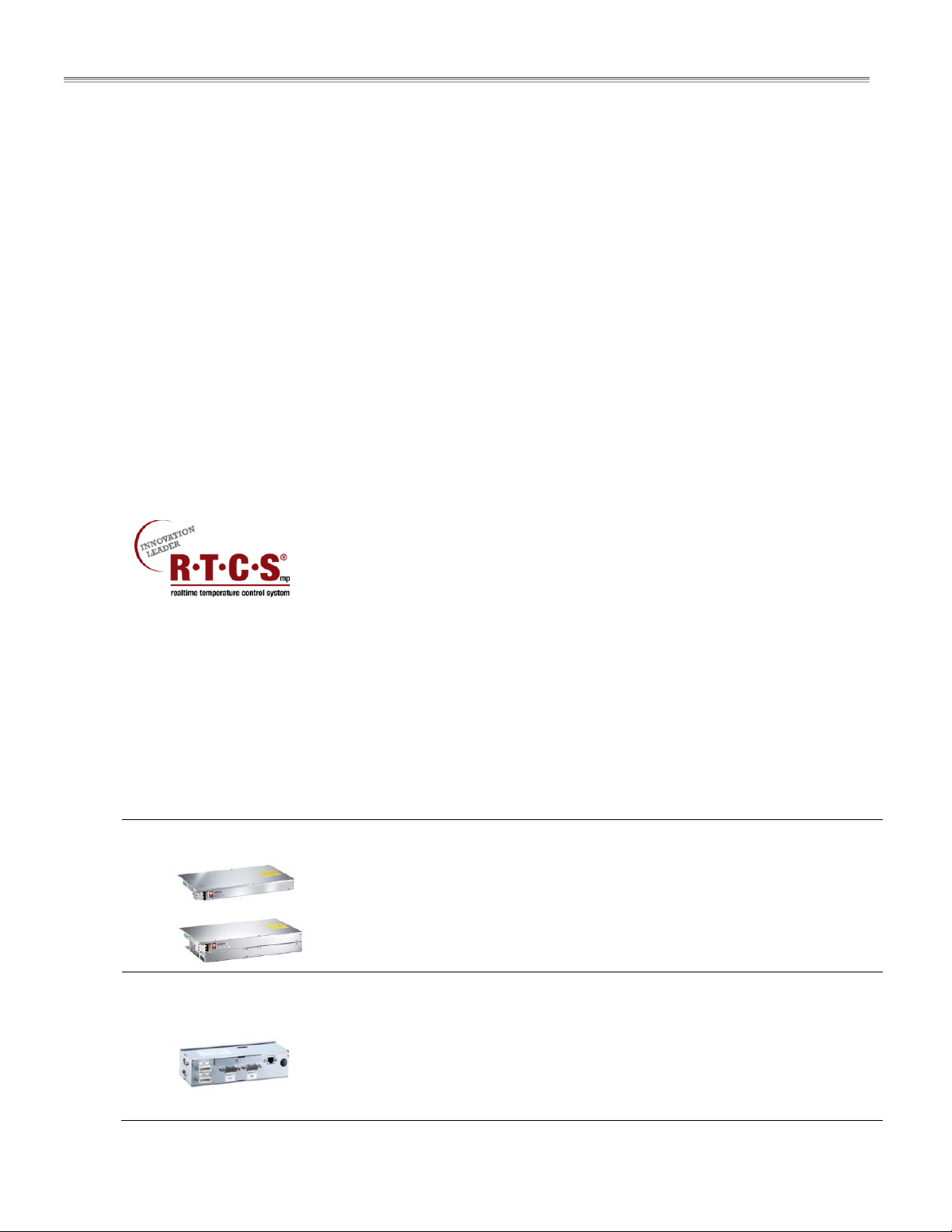
Built with a robust construction, the RTCSmp Induction Module-Line Cooktop is
modular and powerful with the revolutionary RTCSmp-Technology (Realtime
Temperature Control System with Multi-Point sensing). The RTCSmp Technology
Each built-in Module-Line concept consists of: induction generator(s), control unit(s), coil carrier sheet(s) with coils
and sensors, operation unit(s) with rotary switch(es), 6mm thick Ceran glass-top(s), mounting frame(s) with
silicone gaskets, and cables.
Induction Generator:
OR
monitors the energy supply, the state of the induction coil, power board, CPU,
and the cooking zone in realtime. RTCSmp also limits the energy supply during
peak load and its special control eliminates interference noises.
The module-line models include a number of components which allow for
optimal flexibility in designing an efficient kitchen. The unique features of each
component are outlined below. See also chapter 3 Dimensions and Technical
Specifications.
Can be installed up to 10 feet away from other components. | All electrical
connections can be accessed externally through plug connections. | Closed
aluminum housing with an integrated cooling fan to keep electronics cool. |
Integrated air guiding system to direct exhaust air out of the housing.
Versions:
IN/MO 7000FL, IN/MO 14000FL, IN/MO 7000, IN/MO 10000
Control Unit:
8 Part # 4532415 Rev 3 (8/19/14)
Information and diagnostic hub for the whole induction unit. | IR interface with
diagnostic system for service. | Connections to other unit components via plug
connections. | Compact design and easy to install using special installation
tabs/brackets.
Versions:
IN/MO7000/10000, IN/MO7000/14000
Page 9

Components and Features RTCSmp Built-In Module-Line Dual/Quad Cooktops
Coil Carrier Sheet:
Multiple options available: round or full coil in single, dual, quad, or combination of round/full coil
configurations. | Compact and low profile design.
Full Coil (FL): Rectangular in shape. Several large or small pans can be placed on one surface at the same
time.
Round Coil: One pan is used for each heat-zone. Round coils have higher power density and energy
efficiency.
Visual differences between full and round coil carrier sheets and the corresponding glass-tops:
Coil Carrier Sheet
(Coils + Sensors)
Glass Top
Glass-Top:
Installation Frame:
Full Coil
Round Coil
6mm thick Ceran glass-top. | Easy to clean and maintain. | Glass-top patterns
match the corresponding coil versions underneath: Full-Coil or Round-Coil.
Versions:
Dual: 360x360x6mm; 650x375x6mm; 720x360x6mm
Quad: 650x650x6mm; 720x720x6mm
Installation/mounting frame is supplied for flush mounting the coil carrier
sheet(s) and glass-top. | Silicone gaskets (not shown) included.
Five Sizes of Frames:
- for -360 or -360FL dual models with 360x360x6mm glasstop
- for -650 or -650FL dual models with 650x375x6mm glasstop
- for -720 or -720FL dual models with 720x360x6mm glasstop
- for -650 or -650FL quad models with 650x650x6mm glasstop
- for -720 or -720FL quad models with 720x720x6mm glasstop
Operation Unit:
The power switch (Operation Unit) regulates the temperature in power levels 1
to 12. | Simple to operate; adjust the temperature setting simply by turning the
knob. | LED light indicator (not shown) signals the ON/OFF state, pan detection
process and error codes. | Pre-assembled with plastic knob, LED light and cable
(1-meter).
Cable Kit:
2.5-meter cable kit(s) for 208V or 400V is included. Each kit includes cables for
induction coils, sensors, and CAN/BUS connections. Fan cables are included
where applicable. Induction coil cable std. length, 2.5m/98”; sensor cable,
1m/39”; CAN/BUS cable, std. 3m/118”.
Optional:
4-meter Cable Kit (208V); 4-meter Cable Kit (400V); 6-meter Cable Kit (208V); 6meter Cable Kit (400V)
Part # 4532415 Rev 3 (8/19/14) Page 9
Page 10

Dimensions and Technical Specifications RTCSmp Built-In Module-Line Dual/Quad Cooktops
T
3 Dimensions and Technical Specifications
3.1 Rating Plate
he rating plate specifies important information such as model number,
serial number, and electrical specifications. The rating plate is affixed to
the side of the induction generator, next to the mains connection.
3.2 Nomenclature and Models
Series Style/
Function
MO =
module-line
DU = Dual 7000
DU = Dual
with FL=Full
coil(at end)
QU = Quad 14000
QU = Quad
with FL=Full
coil(at end)
3.3 Dimensions
For the dimensions of the components, please refer to the technical drawings in section 4 Installation.
Power
(Watt)
10000
7000
14000
20000
21000
24000
28000 650 x 650
Glass Size
(mm)
360 x 360
650 x 375
720 x 360
360 x 360
650 x 375
720 x 360
650 x 650
720 x 720
720 x 720
Models
MO DU 7000-360, MO DU 10000-360
MO DU 7000-650, MO DU 10000-650
MO DU 7000-720, MO DU 10000-720
MO DU 7000-360FL, MO DU 14000-360FL
MO DU 14000-650FL
MO DU 14000-720FL
MO QU 14000-650, MO QU 20000-650
MO QU 14000-720, MO QU 20000-720
MO QU 21000-720
MO QU 24000-720
MO QU 28000-650FL
MO QU 28000-720FL
3.4 Models and Components Charts
Models and Components Charts are provided in section 4 Installation. For each model, a list of components and
their electrical connections are shown. Quantities are specified on the charts.
10 Part # 4532415 Rev 3 (8/19/14)
Page 11

Dimensions and Technical Specifications RTCSmp Built-In Module-Line Dual/Quad Cooktops
3.5 Electrical Specifications
#
Model - DUAL Voltage Power
208 V AC/ 3Ph/ 60Hz 7000W(2x3500 W)/ 22A 1 AWG 10
MO DU 7000 360 FL
440 V AC/ 3Ph/ 50Hz 7000W(2x3500 W)/ 10A 1 1.5mm2
MO DU 7000 360
MO DU 7000 650
MO DU 7000 720
MO DU 10000 360
MO DU 10000 650
MO DU 10000 720
MO DU 14000 360 FL
MO DU 14000 650 FL
MO DU 14000 720 FL
Model - QUAD Voltage Power
208 V AC/ 3Ph/ 60Hz 7000W(2x3500 W)/ 22A 1 AWG 10
400 V AC/ 3Ph/ 50Hz 7000W(2x3500 W)/ 11A 1 1.5mm2
440 V AC/ 3Ph/ 50Hz 7000W(2x3500 W)/ 10A 1 1.5mm2
208 V AC/ 3Ph/ 60Hz 10000W(2x5000 W)/ 30A 1 AWG 8
400 V AC/ 3Ph/ 50Hz 10000W(2x5000 W)/ 16A 1 2.5mm2
440 V AC/ 3Ph/ 50Hz 10000W(2x5000 W)/ 15A 1 2.5mm2
208 V AC/ 3Ph/ 60Hz 14000W(4x3500 W)/ 22A 2 AWG 10
400 V AC/ 3Ph/ 50Hz 14000W(4x3500 W)/ 11A 2 1.5mm2
440 V AC/ 3Ph/ 50Hz 14000W(4x3500 W)/ 10A 2 1.5mm2
208 V AC/ 3Ph/ 60Hz 14000W(4x3500 W)/ 22A 2 AWG 10
MO QU 14000 650
MO QU 14000 720
400 V AC/ 3Ph/ 50Hz 14000W(4x3500 W)/ 11A 2 1.5mm2
440 V AC/ 3Ph/ 50Hz 14000W(4x3500 W)/ 10A 2 1.5mm2
208 V AC/ 3Ph/ 60Hz 20000W(4x5000 W)/ 30A 2 AWG 8
MO QU 20000 650
MO QU 20000 720
400 V AC/ 3Ph/ 50Hz 20000W(4x5000 W)/ 16A 2 2.5mm2
440 V AC/ 3Ph/ 50Hz 20000W(4x5000 W)/ 15A 2 2.5mm2
21000W(Round Coil
208 V AC/ 3Ph/ 60Hz
2x3500W + Full Coil
4x3500 W)/ 22A
21000W(Round Coil
MO QU 2100 720
2x3500W + Full Coil
4x3500 W)/ 11A
21000W(Round Coil
440 V AC/ 3Ph/ 50Hz
2x3500W + Full Coil
4x3500 W)/ 10A
24000W(Round Coil
208 V AC/ 3Ph/ 60Hz
2x5000W + Full Coil
4x3500 W)/ 30A
24000W(Round Coil
MO QU 2400 720
400 V AC/ 3Ph/ 50Hz
2x5000W + Full Coil
4x3500 W)/ 16A
24000W(Round Coil
440 V AC/ 3Ph/ 50Hz
2x5000W + Full Coil
4x3500 W)/ 15A
208 V AC/ 3Ph/ 60Hz 28000W(8x3500 W)/ 22A 4 AWG 10
MO QU 28000 650 FL
MO QU 28000 720 FL
400 V AC/ 3Ph/ 50Hz 28000W(8x3500 W)/ 11A
440 V AC/ 3Ph/ 50Hz 28000W(8x3500 W)/ 10A
Conductor
Circuits
#
Circuits
Size
Conductor
Size
3 AWG 10
3 1.5mm2
3 1.5mm2
(1x) AWG 8
3
(2x) AWG 10
(1x) 2.5mm
3
(2x) 1.5mm
(1x) 2.5mm
3
(2x) 1.5mm
4
4
1.5mm2
1.5mm2
# Coils
rectangular
coils
2 round
coils
2 round
coils
rectangular
coils
# Coils
round coils
round coils
2 round + 4
rectangular
coils
2 round + 4
2
rectangular
2
coils
2
2
rectangular
coils
2
4
4
4
8
#Cook-
Zones
1 400 V AC/ 3Ph/ 50Hz 7000W(2x3500 W)/ 11A 1 1.5mm2
2
2
2
#Cook-
Zones
4
4
4 400 V AC/ 3Ph/ 50Hz
4
4
Part # 4532415 Rev 3 (8/19/14) Page 11
Page 12

Dimensions and Technical Specifications RTCSmp Built-In Module-Line Dual/Quad Cooktops
3.6 Operating Conditions
Max. Tolerance of Nominal Supply Voltage +6 /-10 %
Network Impedance (Zmax.) 0.25Ω
Supply frequency 50/60 Hz
2
)
2
)
2
))
Amperage Nominal Value — 400V, 3Ph
10A for the 7kW generator (4 x 1.5mm
15A for the 10kW generator (4 x 2.5mm
2 x 10A for the 14kW generator (2 x (4 x 1.5mm
20A for the 7kW generator (4x AWG 10)
Amperage Nominal Value — 208V, 3Ph
Ingress Protection class IP X0 (Protection by customer required.)
Maximum Ambient Temperature
Maximum Relative Air Humidity
Temperature/Power Regulator Potentiometer 10 kOhm
LED Indicator Lamp 24VDC / max. 40mA (Green)
Clearance from materials for generator
Min. Induction Cooking Pan Diameter 5” (12cm)
Max. Air Flow of Fan is 70.63 cfm (120 m3 /h), Fresh Air Inlet Opening of 10.08 sq. in. (6500 mm2) is required.
3.7 Compliances
North American models:
ETL recognized* in compliance with UL 197, CSA C22.2 No.109, NSF-4. Complies with FCC part 18, ICES-001
29A for the 10kW generator (4x AWG 8)
2 x 20A for the 14kW generator (2 x (4 x AWG 10))
In Storage -4°F to +158°F (-20°C to +70°C)
In Operation +41°F to +104°F (+5°C to +40°C)
In Storage 10% to 90%
In Operation 30% to 90%
Min. 1.57”(40mm) for air intake and exhaust openings
Min. 0.39”(10mm) for side clearance
CE models comply with the latest European Norms:
EN 60335-1, EN 60335-2-36, EN 62233 (EMC/EMV)
*see section 4.1.
12 Part # 4532415 Rev 3 (8/19/14)
Page 13

Installation RTCSmp Built-In Module-Line Dual/Quad Cooktops
4 Installation
4.1 Important Safety & Electrical Requirements
This appliance component requires additional features and components to comply with appliance and
electrical standards. It is the responsibility of the customer and installer to interpret and comply with all
applicable safety and electrical standards.
o This product requires the addition of:
A suitable non-flammable electrical enclosure; a means to conceal and protect
components and wiring.
Grounding and bonding to the enclosure.
Warning and caution labels and other markings required by electrical and safety
standards.
Markings to show appliance ratings and end manufacturer information.
Investigation by local electrical authority.
o Depending on the application and configuration of this product, consider the addition of:
Field supply connection terminals.
Branch circuit protection.
Fans, ventilation or cooling systems and controls.
The installation, including electrical installation, must be carried out by registered installation contractors
only. The contractors are responsible for interpreting all instructions correctly and performing the
installation in compliance with national and local regulations. The warning signs and rating plates on the
cooking equipment must strictly be followed.
Read ALL SECTIONS carefully, comply with all requirements listed and ensure all inspection is done by
qualified personnel.
Refer to the technical data given in chapter 3 Dimensions and Technical Specifications.
Induction equipment that is not installed correctly will have warranty voided. See Warranty, p.2.
4.2 Installation Overview and Installation Clearance
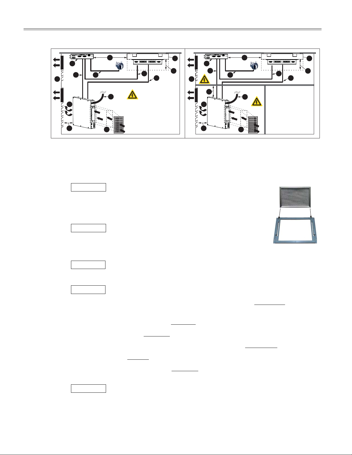
4.2.1 Installation Overview
To protect the induction unit and wiring, we recommend isolating the generator, the coil carrier sheets, and the
wires in separate electrical compartments inside the cabinet (Figure B). The illustration also shows a simplified
representation of an installation.
IMPORTANT To ensure reliability of the induction unit, the cabinet/compartments must have sufficient
ventilation for the exhaust. Buildup of hot exhaust air will cause the unit to reduce power or to
switch-off. See 3.5 Operating Conditions.
Part # 4532415 Rev 3 (8/19/14) Page 13
Page 14
Installation RTCSmp Built-In Module-Line Dual/Quad Cooktops
Figure
A
Figure
B
I I
J
E
K
D
F
L
O
C
M
N
G
H
J
K
E
F
D
F
L
O
C
M
N
G
H
Figure (A) All components are installed inside one single compartment and the wires are exposed.
Figure (B) The interior space of the cabinet is divided. The coil carrier sheet, the control unit and their wiring
are protected inside the upper compartment; the generator and its wiring are protected inside
the lower compartment. Extra storage space can also be created.
IMPORTANT Fresh air intake. It is recommended to isolate the fresh air intake
(C)
Air Intake Filter
from the exhaust air via an air intake duct, an air outlet duct or both. Filter the
intake air with a removable air filter (right, an example).
(D) Hot air exhaust from the induction generator.
IMPORTANT Air exhaust opening installed on the cabinet. It is highly
(E)
recommended to install a fan or fans on the cabinet to pull hot exhaust air away
from the electronic equipment. Buildup of hot exhaust air will cause the induction
Filter Holder
Filter Holder
unit to reduce power or to switch-off.
(F)
CLEARANCE Minimum clearance, see section 4.2.2.
(G) A Coil Carrier Sheet and Mounting Frame.
(H)
CLEARANCE Minimum clearance, see section 4.2.2.
(I) Maximum distance between the control unit and the coil carrier sheet is 80 cm/31.5”. See (M).
(J) Control Unit.
(K) RJ45 CAN/BUS cable, standard length= 3m / 118” , to connect the control unit to the generator.
(L) Power switch cable, length= 0.9m / 36” , to connect the operation unit (power switch) to control unit.
Maximum distance between the control unit and the operation unit: 80 cm/31.5”.
(M) Sensor cable, length= 1m / 39” , to connect the sensors on the coil carrier sheet to the control unit.
(N) Induction coil cable, standard length= 2.5m / 98” , to connect the induction coils on the coil carrier
sheet to the generator.
IMPORTANT Always route sensor and communication cables separately and away from the coil
cables.
(O) Main power cable connection. Power cable is not provided.
14 Part # 4532415 Rev 3 (8/19/14)
Page 15
Installation RTCSmp Built-In Module-Line Dual/Quad Cooktops
4.2.2 Installation Clearance
a
Cable Bend /
Connection Clearance
b
c
c
c
b
Induction
a
c
Generator
Control
a
Unit
(minimum)
127mm / 5” 40mm / 1.57”
70mm / 2.75” --
b
Air Exhaust/
Intake Clearance
(minimum)
c
Clearance
(minimum)
10mm / 0.39”
(sides, top,
and bottom)
38mm / 1.5”
(for service
interface)
100mm /
c
a
a
Coil Carrier
Sheet
Operation
Unit
127mm / 5” --
12.7mm / 0.5“ -- --
3.94”
(below coil
carrier sheet)
4.3 Induction Generator
IMPORTANT
The maximum operating temperature for the induction unit must not exceed 104F (40C).
Buildup of hot exhaust air around the induction unit will cause the unit to reduce power or to switch-off.
Recommended: At an appropriate location on the cabinet, install an exhaust fan to force hot air out the
cabinet and away from the induction unit. Consult an electrical or installation expert for the most
appropriate location to install a cabinet exhaust fan.
Recommended: Filter the intake air with an air intake filter. Kitchen air often contains grease laden
vapors. Grease deposits inside the generator may cause overheating. Failure to provide clean fresh
cooling air may void warranty.
NOTE: Additional fans and cooling controls are the responsibility of the customer and installer.
Clearance: refer to the data in section 3.5 Operating Conditions.
Part # 4532415 Rev 3 (8/19/14) Page 15
Page 16

Installation RTCSmp Built-In Module-Line Dual/Quad Cooktops
4.3.1 Location
It is possible to install the induction unit near heat-producing or steam-producing equipment such as an
oven or a fryer. However, use an external fan to pull hot air, greasy fume, and moisture away from the
induction unit.
If the generator is installed directly under the induction coil or in the same chamber of as the coil, ensure
the ventilation system will keep the ambient temperature below 104F (40C).
Keep all combustible materials, vapors or liquids away from the generator.
Ensure the installed location of the generator is safe from any ingress of liquid into the immediate
vicinity.
The generator can be mounted in any orientation as long as:
o the equipment and cable connections are accessible for maintenance and service.
o the fresh air intake and exhaust air outlet are not blocked.
4.3.2 Ventilation
Maximum air flow of the fan is 70.63 cfm (120 m
sq. in. (6500 mm
2
) is required around the fresh air intake.
3
per hour) and therefore a minimum opening of 10.08
An optimal air circulation and air flow must not be restricted by installation.
The in-take air and exhaust air must not mix. To avoid build-up of hot exhaust air inside the cabinet, use a
fan to draw the exhaust air out, or provide a separate exhaust air plenum.
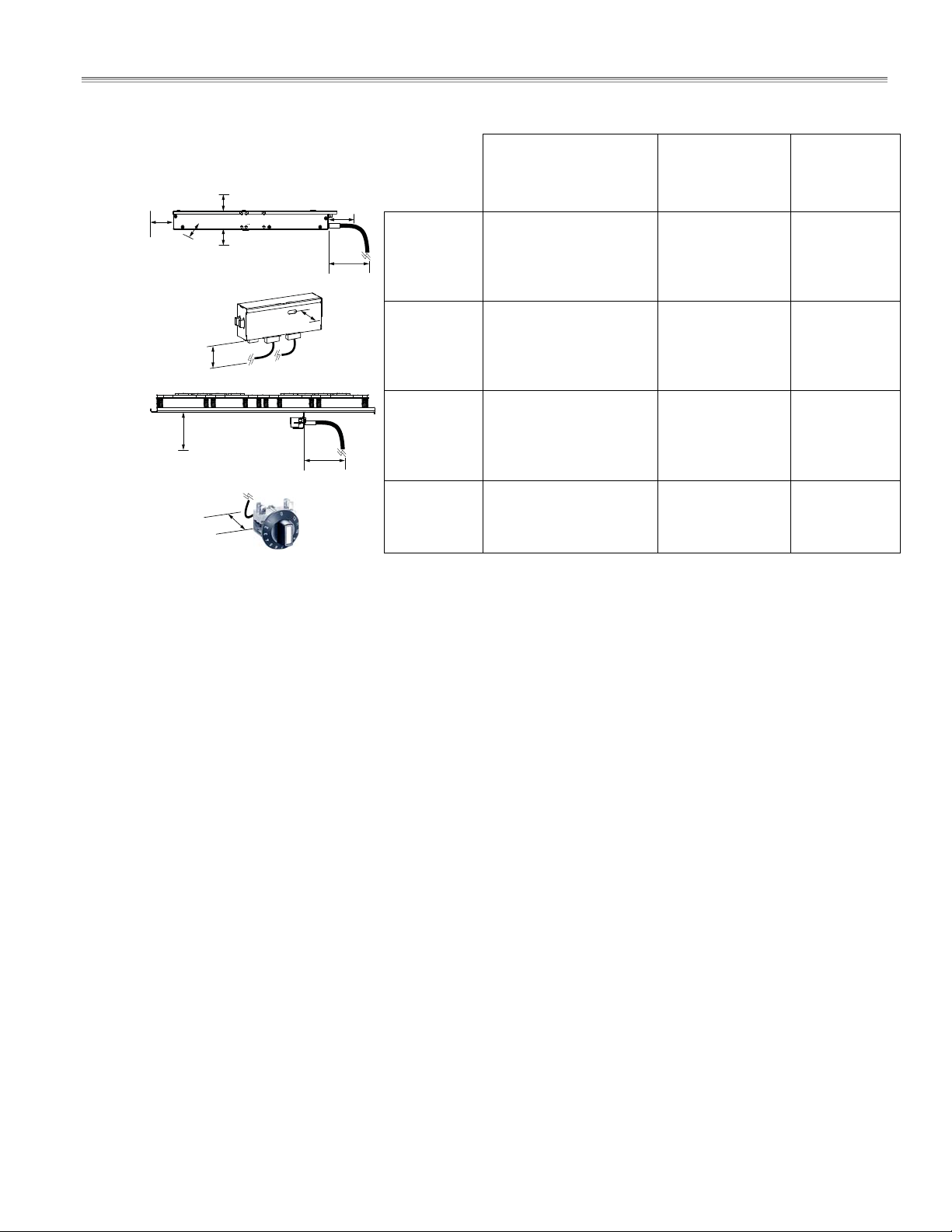
4.3.3 Dimensions
Models: MO DU 7000/ 10000 MO QU14000/ 20000/ 21000/ 24000
CAN/BUS
1.57”
(40 mm)
coil
connection
eld 1+2
1.02”
(26 mm)
3.98”
(101 mm)
fan
mains connection
air supply
6.02” (153 mm)
6.81” (173 mm)
air exhaust
6.22”
(158 mm)
3.98”
(101 mm)
2.58”
(65.5 mm)
air exhaust
clearance
14.17”
(360 mm)
23.62” (600 mm)min 1.57” (40 mm) min 5” (127mm)
cable bend
clearance
air supply
23.62” (600 mm)
16 Part # 4532415 Rev 3 (8/19/14)
Page 17

Installation RTCSmp Built-In Module-Line Dual/Quad Cooktops
Models: MO DU 14000/ 20000 MO QU 21000/ 24000/ 28000
CAN/BUS
1.57” (40 mm)
0.91” (23 mm)
1.57” (40 mm)
mains connection
eld 2
coil connection
eld 1
6.02” (153 mm)
6.81” (173 mm)
mains connection
eld 1
coil connection
eld 2
5.16”
(131 mm)
2.09”
(53 mm)
min 1.57” (40 mm)
air exhaust
clearance
23.62” (600 mm)
23.62” (600 mm)
min 5” (127mm)
cable bend
clearance
air
supply
3.98”
(101 mm)
6.22”
(158 mm)
3.98”
(101 mm)
14.17”
(360 mm)
4.4 Control Unit and Operation Unit (Power Switches)
4.4.1 Location
Distance of the control unit from the coil carrier sheet: MAX 800mm / 31.5”.
Distance of the control unit from the operation units (power switches): MAX 800mm / 31.5”.
Keep the Service Interface window on the control unit accessible for service.
Ensure the equipment and cable connections are accessible for maintenance and service.
4.4.2 Ventilation
It is possible to install the induction unit near heat-producing or steam-producing equipment such as an
oven or a fryer. However, use an external fan to pull hot air, greasy fume, and moisture away from the
induction unit.
The maximum operating temperature for the induction unit must not exceed 104F (40C).
Part # 4532415 Rev 3 (8/19/14) Page 17
Page 18

Installation RTCSmp Built-In Module-Line Dual/Quad Cooktops
4.4.3 Mounting Methods
Control Unit:
o Installation brackets are provided to mount the control unit. See “Mounting Version” in section
4.4.4 Dimensions– Control Unit.
o Mount the control unit directly onto the cabinet compartment wall/shelf, or
o Stud-mount the control unit onto the back of the cabinet front panel. Use the dimensions
provided in section 4.4.5 Dimensions Guide as a template to install the control unit, the
operation units (power switches) and the LED Indicator lights.
o Keep the Service Interface window on the control unit accessible for service.
IMPORTANT: To prevent the operation units (power switches) from rotating during operation,
secure these units onto the panel with two (2) M4 screws. See section 4.4.5 Dimensions Guide.
4.4.4 Dimensions – Control Unit
3.35” (85 mm)
0.91”
(23 mm)
7.87” (200 mm)
0.51” (13 mm)
0.79” (20 mm)
0.31” (8 mm)
2.60” (66 mm)
0.51” (13 mm)
1.18” (30 mm)
2.95” (75 mm)
1.85” (47 mm)
Cable Bend Radius/
Service Clearance
min 70mm / 2.75”
0.98” (25 mm)
0.39” (10 mm)
1.77” (45 mm)
0.59”
(15 mm)
(15 mm)
0.59”
(15 mm)
Service Interface
Clearance
min 38mm / 1.5”
0.59”
0.51”
(13 mm)
18 Part # 4532415 Rev 3 (8/19/14)
Page 19

Installation RTCSmp Built-In Module-Line Dual/Quad Cooktops
4.4.5 Dimensions Guide (Holes/Studs)
Dimensions in mm [inch]
opening LED
eld 1/2
backside stove cover
30 [1.18]
welding bolts
M4 / M5
opening LED
eld 1/2
A
control unit
without EMI
8.2 [0.32]
5 [1.2]
14 [0.55]
with or without EMI
38 [1.50]
X
holes for
rotary knob
xation
eld 1/2
min.
125 [4.92] 155 [6.1]
27 [1.06]
min.
A
DETAIL
10.2 [0.4]
5 [1.2]
14 [0.55]
28 [1.10]
Y
Y
226 [8.96]
min.
X
101 [3.98]
with EMI
min.
with EMI
welding bolts, for mounting version 1, 2, 3
X
welding bolts, for mounting version 4
Y
30 [1.18]
57 [2.24]
holes for
rotary knob
xation
eld 1/2
Part # 4532415 Rev 3 (8/19/14) Page 19
Page 20

Installation RTCSmp Built-In Module-Line Dual/Quad Cooktops
4.5 Coil Carrier Sheet, Ceran Glass and Mounting Frame
4.5.1 Location & Ventilation Requirements for Coil Carrier Sheet Installation
A Coil Carrier Sheet houses the induction coil and sensor assemblies, which are installed directly under
the glass-top.
Distance from the control unit to the coil carrier sheet: MAX. 31.50” / 800mm.
Clearance below the coil carrier sheet: MIN. 3.94” / 10 cm. This clearance must be maintained for
installation and service. Ensure this area can be easily accessible for maintenance and service.
55 mm / 2.17” (without compression)
50 mm +/- 2mm (with correct compression
when installed)
Optimal contact pressure
of the coil carrier on
Ceran glass 5mm.
Clearance Minimum
10 cm / 3.94”
Below Coil Carrier Sheet
MUST NOT install or store any metallic objects or components below the induction coils.
When placed in the vicinity of other coils, objects/components that are made of steel must be non-
magnetic.
Prevent moisture, hot ambient air or greasy fume being drawn into the installation compartment,
especially when the appliances are near a fryer or oven.
o Maintain ambient temperature below 104F (40C) for proper functioning of the unit.
o Install extra fan in the compartment to remove any hot air away from the induction unit.
Keep all the combustible materials, vapors or liquids away from the coil carrier sheets.
4.5.2 Countertop Cut-outs Dimensions
NOTE: The cut-out dimensions are specified in the drawings of the mounting frames. These dimensions include
widths for silicone sealant, 4mm on each side.
Coil Connection to
Generator
49mm/
1.93”
Ceran Glass
Silicone Gasket
Coil Carrier Sheet
Distance Maximum
800 mm / 31.5”
Distance Maximum
800 mm / 31.5”
To Induction
Generator
A line of silicone sealant of 4mm wide must be applied around the glass perimeter to prevent any ingress of liquid
into the unit.
4.5.3 Correct Orientation – Coil Carrier, Glass and Frame
When designing a kitchen layout with quad models, ensure to orient the mounting frame correctly to allow for
ease of installation and service. See section 4.5.5 Installation Steps.
For any quad model with full coils, the orientation of the frame also needs to match the orientations of the glass
and the coil carrier sheets. Follow the chart below to ensure the correct placement is incorporated into the
kitchen design and installation.
20 Part # 4532415 Rev 3 (8/19/14)
Page 21

Installation RTCSmp Built-In Module-Line Dual/Quad Cooktops
4.5.4 Mounting Frames
Mounting Frame for countertop thickness of 1.5mm to 3mm / 16- to 10-gauge (Typ.):
Specific mounting frame is provided with your unit for a typical installation. Refer to sections 4.5.4.1 to
4.5.4.5 for frame and countertop cut-out dimensions. See section 4.5.5 for installation instructions.
Mounting Frame for countertop thickness of 20-30mm/ 1”:
For an application with countertop thickness about 1” or 20 – 30 mm, a custom built mounting frame is
required to flush-mount the glasstop and install the coil carrier sheet properly. For an example of a custom
built frame, refer to section 4.5.6 Custom-Built Mounting Frame.
Part # 4532415 Rev 3 (8/19/14) Page 21
Page 22

Installation RTCSmp Built-In Module-Line Dual/Quad Cooktops
4.5.4.1 Dimensions – Mounting Frame [for glasstop size 360x360mm]
4.5.4.2 Dimensions – Mounting Frame [for glasstop size 375x650mm]
22 Part # 4532415 Rev 3 (8/19/14)
Page 23

Installation RTCSmp Built-In Module-Line Dual/Quad Cooktops
4.5.4.3 Dimensions – Mounting Frame [for glasstop size 650x650mm]
4.5.4.4 Dimensions – Mounting Frame [for glasstop size 360x720mm]
Part # 4532415 Rev 3 (8/19/14) Page 23
Page 24

Installation RTCSmp Built-In Module-Line Dual/Quad Cooktops
4.5.4.5 Dimensions – Mounting Frame [for glasstop size 720x720mm]
24 Part # 4532415 Rev 3 (8/19/14)
Page 25

Installation RTCSmp Built-In Module-Line Dual/Quad Cooktops
4.5.5 Installation Steps
IMPORTANT
COUNTERTOP CUT-OUT DIMENSIONS, see section 4.5.4 Mounting Frames.
When installing two coil carrier sheets on the same frame, you must install a non-magnetic steel
partition plate in between them. This will isolate the magnetic fields and prevent the fields from
interfering each other.
IMPORTANT
To protect the induction unit from water penetration, you must apply and bond the silicone adhesive
properly to create a water-tight seal. Before you begin the installation, it is very important to use isopropyl
alcohol (minimum 70%) or equivalent to clean the flanges/edges and the counter surfaces where the
silicone adhesive will be applied.
To install the mounting frame and Ceran glass:
min 1.5
[0.06]
B
A
A. Orientation: The mounting frame assembly has a set of retaining rails that are hinged at the BACK of the
frame. The rails can drop down at the FRONT for installing the coil carrier sheet. Ensure to install the
frame in the correct orientation according to the design/layout plan.
B. Secure the mounting frame to the underside of the counter surface. Stud-mounting method is shown in
illustration.
Part # 4532415 Rev 3 (8/19/14) Page 25
Page 26

Installation RTCSmp Built-In Module-Line Dual/Quad Cooktops
D
C
E
F
min 1.5 [0.06]
C. NOTE: BEFORE applying any silicone adhesive, CLEAN glass, silicone gaskets, frame, and tops with
isopropyl alcohol or equivalent.
Apply a line of silicone adhesive PACTAN onto the bracket before placing the silicone gaskets/stripes
(provided). After placing the silicone stripe onto the bracket, apply silicone adhesive on top of the
silicone stripe. PACTAN is not provided (part number = 70000015).
D. Examine the Ceran glass before installation.
i. Then carefully lower the glass onto the silicone stripe.
NOTE: When installing multiple glass-tops side by side, ensure to orient all the logos on the
glass-tops the same direction.
ii. Align the edges of the glass with the edges of the countertop cut-out.
E. Level the glass by adjusting the screws.
F. To provide a water tight seal, apply silicone sealant completely around, filling any gaps between the
glass and the counter-top surface.
IMPORTANT Let the silicone adhesive to cure properly before installing the coil carrier sheet.
To install the coil carrier sheet:
NOTE: Before installation, check the kitchen plan and coil layout (orientation) to ensure the side with the plug
connectors on the coil sheet is oriented correctly for wiring and service.
G. Loosen the two screws to free the retaining rails. The rails are hinged at the hooks at the back.
26 Part # 4532415 Rev 3 (8/19/14)
Page 27

Installation RTCSmp Built-In Module-Line Dual/Quad Cooktops
H. Guided by the retaining rails, carefully insert the back end of the coil carrier sheet into the frame. The coil
and sensor connectors should be facing the front. The retaining rails provide additional support to the
coil carrier sheet.
I. While holding the coil carrier sheet together with the retaining rails, swing the rails back into the original
position and tighten the screws.
J. The coils and temperature sensors installed on the coil carrier sheet must exert a constant pressure of
5mm to the Ceran glass. This pressure ensures the temperature monitoring to work properly. Do not
allow any gap between the temperature sensors and the glass. You MUST set the pressure correctly.
To adjust the pressure correctly:
i. Bolts of the coil carrier sheet must protrude 5mm from the coil carrier sheet.
ii. Distance from the underside of the coil carrier sheet to the Ceran glass: 50mm +/- 2mm.
iii. When extra compression is required, install M4 screws (not provided) to the retaining rails. Tighten
or loosen the M4 screws to adjust to the correct pressure.
50.1mm
[1.97”]
ii
J
J
i
5mm
J
iii
Part # 4532415 Rev 3 (8/19/14) Page 27
Page 28

Installation RTCSmp Built-In Module-Line Dual/Quad Cooktops
4.5.6 Custom-Built Mounting Frame
Mounting Frame for countertop thickness of 1.5mm to 3mm / 16- to 10-gauge (Typ.): See section 4.5.4.
Mounting Frame for countertop thickness of 20-30mm/ 1”:
For an application with countertop thickness about 1” or 20 – 30 mm, a custom-built mounting frame is
required to flush-mount the glasstop and install the coil carrier sheet properly. When designing an
appropriate frame, use the design criteria and the example below as your guide.
NOTE: You may re-use existing parts from the mounting frame provided.
NOTE: Refer to section 4.5.4 and 4.5.5 for cut-out dimensions and recommended installation procedure.
NOTE: Please contact Garland if you would require assistance on designing a proper frame. CAD files for
the example shown in this section are available upon request.
Mounting Frame Design Criteria
The coil carrier sheet(s) should be easily removable for service/maintenance without taking out the glass-
top.
Height-adjustable feature for leveling the unit during installation is desirable.
Use 10- to 14-gauge metal (typ. 12-gauge) for the mounting frame.
When installing two coil carrier sheets on the same frame, you must install a non-magnetic steel
partition plate in between them. This will isolate the magnetic fields and prevent the fields from
interfering each other.
The mounting frame has to support the total weight of the glass, the coil carrier sheet(s), the cookware,
and food product.
Critical dimensions:
o Countertop cut-out dimension, see section 4.5.4.
o Distance from the underside of the coil carrier sheet to the Ceran glass after installation: 50mm
+/- 2mm.
o Thickness of glass + silicone gasket + silicone seal = 6mm + 3mm + approx. 0.5mm = total
approx. 9.5mm. See section 4.5.5 steps C to F.
28 Part # 4532415 Rev 3 (8/19/14)
Page 29

Installation RTCSmp Built-In Module-Line Dual/Quad Cooktops
Custom-Built Mounting Frame Example
C
Support/Leveling
plates for securing/
leveling the glass
and the coil carrier
sheet(s).
*
H
Tabs, attached to
cross bar, to hold
the retaining rails.
E
A lip/ange for the glass to sit on.
I
Holes for screws to
compress further the coil
carrier sheet to the glass.
F
Retaining rails hook
and hinge at the
back. (see (G))
*
*
Retaining rails secured to taps with screws.
Easy to insert or remove coil carrier sheet
for maintenance and service by removing
screws and dropping at the front. (see (F))
G
B
A NON-MAGNETIC steel partition
plate between two coil carrier sheets
for quad models.
D
Cross-bar for attaching
the retaining rails and
partition plate.
* Welded structure
recommended.
Support bar for
strengthening the
countertop and
securing the mounting
frame.
A
Silicone Seal
Countertop
Silicone Gasket
Ceran Glass Top
E
Countertop
Support Bar
Shown
A
C
Retaining Rail
F G
Cross Section View (simplied)
B
Assembly
View
Countertop
AC
Part # 4532415 Rev 3 (8/19/14) Page 29
Page 30

Installation RTCSmp Built-In Module-Line Dual/Quad Cooktops
OPERATION
UNIT
CONTRO L
UNIT
GLASSROUND COILS,
DUAL MODELS
CABLE KITGENERATOR
COIL CARRIER SHEET
(coils + sensors)
MOUNTING FRAME
4.6 Models, Components and Cable Connections
4.6.1 CHART 1 – Module-Line Round Coil Dual Models
MODU
7000 360
MODU
10000 360
7000 360
10000 360
Installation
MODU
7000 650
MODU
7000 720
(2x)
360 x 360 x 6 mm
(2x)
360 x 360 x 6 mm
poti/LED
connection
eld1
poti/LED
connection
eld2
(1x)
375 x 650 x 6 mm
(1x)
375 x 720 x 6 mm
(2x)
Frame for
360 x 360mm glass
(2x)
Frame for
360 x 360mm glass
sensor connection (eld 1)
(1x)
Frame for
375 x 650mm glass
(1x)
Frame for
375 x 720mm glass
(1x)
IN/MO7000
(1x)
IN/MO10000
CAN/BUS
coil connection Field 1 + 2
sensor connection (eld 2)
(1x)
IN/MO7000
(1x)
IN/MO7000
(2x)
344 x 355 mm Round
Coil, Each 3.5 kW
(2x)
344 x 355 mm, Round
Coil, Each 5.0 kW
(1x)
319 x 624 mm,
Round Coil, Each 3.5 kW
(1x)
354.5 x 689 mm
Round Coil, Each 3.5 kW
mains
connection
eld 1 + 2
(1x)
IN/MO 7000/10000
(1x)
IN/MO 7000/10000
Splitter
(included)
(1X)
IN/MO 7000/10000
(1x)
IN/MO 7000/10000
eld 1 eld 2
(2x)
(2x)
(2x)
(2x)
(1x)
IN/MO 7000/10000
-360 Cable Kit,
2.5-meter
(Options:
4-meter or
6-meter Kit)
(1x)
IN/MO 7000/10000
-360 Cable Kit,
2.5-meter
(Options:
4-meter or
6-meter Kit)
(1x)
IN/MO 7000/10000
Cable Kit, 2.5-meter
(Options:
4-meter or
6-meter Kit)
(1x)
IN/MO 7000/10000
Cable Kit, 2.5-meter
(Options:
4-meter or
6-meter Kit)
(1x)
IN/MO 7000/10000
Cable Kit, 2.5-meter
MODU
10000 650
MODU
10000 720
7000 650
7000 720
10000 650
10000 720
(1x)
375 x 650 x 6 mm
(1x)
375 x 720 x 6 mm
poti/LED
connection
eld1
(1x)
Frame for
375 x 650mm glass
(1x)
Frame for
375 x 720mm glass
CAN/BUS
(1x)
IN/MO10000
(1x)
IN/MO10000
(1x)
319 x 624 mm
Round Coil, Each 5.0 kW
(1x)
354.5 x 689 mm
Round Coil, Each 5.0 kW
mains
connection
eld 1 + 2
(1X)
IN/MO 7000/10000
(1x)
IN/MO 7000/10000
(2x)
(2x)
(Options:
4-meter or
6-meter Kit)
(1x)
IN/MO 7000/10000
Cable Kit, 2.5-meter
(Options:
4-meter or
6-meter Kit)
eld 2
(coil 2)
eld 1
(coil 1)
Installation
poti/LED
connection
eld2
sensor connection (eld 2)
sensor connection (eld 1)
coil connection Field 1 + 2
30 Part # 4532415 Rev 3 (8/19/14)
Page 31

Installation RTCSmp Built-In Module-Line Dual/Quad Cooktops
OPERATION
UNIT
CONTRO L
UNIT
GLASSROUND COIL,
QUAD MODELS
CABLE KITGENERATOR
COIL CARRIER SHEET
(coils + sensors)
MOUNTING FRAME
4.6.2 CHART 2 – Module-Line Round Coil Quad Models
MOQU
14000 650
MOQU
14000 720
MOQU
20000 650
MOQU
20000 720
(1x)
650 x 650 x 6 mm
(1x)
720 x 720 x 6 mm
(1x)
650 x 650 x 6 mm
(1x)
720 x 720 x 6 mm
(1x)
Frame
for 650 x 650mm
glass
(1x)
Frame
for 720 x 720mm
glass
(1x)
Frame
for 650 x 650mm
glass
(1x)
Frame
for 720 x 720mm
glass
(2x)
IN/MO7000
(2x)
IN/MO7000
(2x)
IN/MO10000
(2x)
IN/MO10000
(2x)
319 x 624 mm
Round Coil
Each 3.5 kW
(2x)
354.5 x 689 mm
Round Coil
Each 3.5 kW
(2x)
319 x 624 mm
Round Coil
Each 5.0 kW
(2x)
354.5 x 689 mm
Round Coil
Each 5.0 kW
(2x)
IN/MO 7000/10000
(2x)
IN/MO 7000/10000
(2x)
IN/MO 7000/10000
(2x)
IN/MO 7000/10000
(2x)
IN/MO 7000/10000
Cable Kit, 2.5-meter
(Options:
4-meter or
(4x)
6-meter Kit)
(2x)
IN/MO 7000/10000
Cable Kit, 2.5-meter
(Options:
(4x)
4-meter or
6-meter Kit)
(2x)
IN/MO 7000/10000
Cable Kit, 2.5-meter
(Options:
(4x)
4-meter or
6-meter Kit)
(2x)
IN/MO 7000/10000
Cable Kit, 2.5-meter
(Options:
(4x)
4-meter or
6-meter Kit)
14000 650
14000 720
20000 650
20000 720
Installation
poti/LED
connection
eld1
poti/LED
connection
eld2
poti/LED
connection
eld3
poti/LED
connection
eld4
CAN/BUS
coil connection Field 1 + 2
sensor connection (eld 2)
sensor connection (eld 1)
CAN/BUS
sensor connection (eld 4)
sensor connection (eld 3)
mains
connection
eld 1 + 2
mains
connection
eld 3 + 4
coil connection Field 3 + 4
eld 2
(coil 2)
eld 1
(coil 1)
eld 1 + 2 eld 3 + 4
eld 4
(coil 4)
eld 3
(coil 3)
Part # 4532415 Rev 3 (8/19/14) Page 31
Page 32

Installation RTCSmp Built-In Module-Line Dual/Quad Cooktops
OPERATION
UNIT
CONTROL
UNIT
GLASSFULL COIL,
DUAL MODELS
CABLE KITGENERATOR
COIL CARRIER SHEET
(coils + sensors)
MOUNTING FRAME
4.6.3 CHART 3 – Module-Line Full Coil Dual Models
MODU
7000 360FL
7000 360FL
Installation
MODU
14000 360FL
14000 360FL
Installation
(1x)
360 x 360 x 6 mm
poti/LED
connection
eld1
(2x)
360 x 360 x 6 mm
poti/LED
connection
eld1
poti/LED
connection
eld2
(1x)
Frame
for 360 x 360mm
glass
CAN/BUS
sensor connection (eld 1)
(2x)
Frame for 360 x 360mm
glass
sensor connection (eld 1)
CAN/BUS
mains
eld 2
(1x)
IN/MO7000FL
ventilation (fan) cable connection
coil connection
(1x)
IN/MO14000FL
coil connection Field
ventilation (fan) cable connection
(1x)
344 x 355 mm
2 Rectangular Coils
Each 3.5 kW
1
coil connec
mains
connection
(2x)
344 x 355 mm
2 Rectangular Coils
Each 3.5 kW
mains
connection
eld 1
ventilation (fan) cable connection
tion F
ield 2
(1x)
IN/MO 7000/14000
(1x)
IN/MO 7000/14000
eld 1 eld 2
(1x)
(2x)
(1x)
IN/MO7000FL360 Cable Kit,
2.5-meter
(Options:
4-meter or
6-meter Kit)
(1x)
IN/MO14000
Cable Kit,
2.5-meter
(Options:
4-meter or
6-meter Kit)
MODU
14000 650FL
MODU
14000 720FL
14000 650FL
14000 720FL
Installation
(1x)
375 x 650 x 6 mm
(1x)
360 x 720 x 6 mm
poti/LED
connection
eld1
poti/LED
connection
eld2
sensor connection (eld 2)
(1x)
Frame for 375 x 650mm
glass
(1x)
Frame
for 360 x 720mm
glass
sensor connection (eld 1)
CAN/BUS
sensor connection (eld 2)
(1x)
IN/MO14000FL
(1x)
IN/MO14000FL
coil connection Field 1
ventilation (fan)
cable connection
mains
connection
eld 2
(1x)
319 x 624 mm
4 Rectangular Coils
Each 3.5 kW
(1x)
354.5 x 689 mm
4 Rectangular Coils
Each 3.5 kW
mains
eld 1
coil connection Field 2
(1x)
IN/MO 7000/14000
(1x)
IN/MO 7000/14000
eld 2eld 1
coil 4
(2x)
(2x)
coil 3
coil 2
coil 1
(1x)
IN/MO14000
Cable Kit,
2.5-meter
(Options:
4-meter or
6-meter Kit)
(1x)
IN/MO14000
Cable Kit,
2.5-meter
(Options:
4-meter or
6-meter Kit)
eld 2
eld 1
32 Part # 4532415 Rev 3 (8/19/14)
Page 33

Installation RTCSmp Built-In Module-Line Dual/Quad Cooktops
OPERATION
UNIT
CONTRO L
UNIT
GLASSFULL COIL,
QUAD MODELS
CABLE KITGENERATOR
COIL CARRIER SHEET
(coils + sensors)
MOUNTING FRAME
4.6.4 CHART 4 – Module-Line Full Coil Quad Models
(2x)
MOQU
28000 650FL
(1x)
650 x 650 x 6 mm
(1x)
Frame for
650x 650mm glass
(2x)
IN/MO14000FL
(2x)
319 x 624 mm
4 Rectangular Coils
Each 3.5 kW
(2x)
IN/MO 7000/14000
(4x)
IN/MO14000
Cable Kit,
2.5-meter
(Option:
4-meter or
6-meter Kit)
MOQU
28000 720FL
28000 650FL
28000 720FL
Installation
(1x)
720 x 720 x 6 mm
poti/LED
connection
eld1
poti/LED
connection
eld2
poti/LED
connection
eld3
poti/LED
connection
eld4
(1x)
Frame for
720x 720mm glass
(2x)
IN/MO14000FL
CAN/BUS
eld 1
eld 2
sensor connection (eld 2)
sensor connection (eld 1)
CAN/BUS
eld 3
eld 4
mains
eld 2
mains
eld 4
(2x)
354.5 x 689 mm
4 Rectangular Coils
Each 3.5 kW
ventilation (fan)
cable connection
coil connection Field 1
mains
eld 1
coil
connection
Field 2
ventilation (fan) cable connection
mains
eld 3
sensor connection (eld 4)
sensor connection (eld 3)
(2x)
IN/MO 7000/14000
eld 2
eld 1
eld 1
coil connection Field 3
coil connection Field 4
coil 4
coil 3
coil 2
coil 1
eld 2
(2x)
IN/MO14000
Cable Kit,
2.5-meter
(4x)
(Option:
4-meter or
6-meter Kit)
coil 8
eld 4
coil 7
coil 6
eld 3
coil 5
eld 4eld 3
Part # 4532415 Rev 3 (8/19/14) Page 33
Page 34

Installation RTCSmp Built-In Module-Line Dual/Quad Cooktops
OPERATION
UNIT
CONTRO L
UNIT
GLASS
FULL & ROUND
COILS COMBINED,
QUAD MODELS
CABLE KITGENERATOR
COIL CARRIER SHEET
(coils + sensors)
MOUNTING FRAME
4.6.5 CHART 5 – Module-Line Full and Round Coil Quad Models
MOQU
21000 720
MOQU
24000 720
21000 720
24000 720
Installation
(1x)
720 x 720 x 6 mm
(1x)
720 x 720 x 6 mm
poti/LED
connection
eld1
poti/LED
connection
eld2
poti/LED
connection
eld3
poti/LED
connection
eld4
(1x)
Frame
for
720 x 720mm glass
(1x)
Frame
for
720 x 720mm glass
IN/MO 14000
IN/MO 7000/10000
sensor connection (eld 1)
CAN/BUS
eld 1
eld 2
sensor connection (eld 2)
CAN/BUS
sensor connection (eld 4)
sensor connection (eld 3)
(1x)
IN/MO14000FL
(1x)
IN/MO10000
(1x)
IN/MO14000FL
(1x)
IN/MO10000
coil connection Field 1
ventilation (fan)
cable connection
mains connection
eld 2
(1x)
354.5 x 689 mm
4 Rectangular Coils
Each 3.5 kW
(1x)
354.5 x 689 mm
2 Round Coil
Each 3.5 kW
(1x)
354.5 x 689 mm
4 Rectangular Coils
Each 3.5 kW
(1x)
354.5 x 689 mm
2 Round CoilS
Each 5.0 kW
mains
connection
eld 1
coil connection
Field 2
coil connection Field 3 + 4
eld 1
mains
connection
eld 3 + 4
(1x)
IN/MO 14000
(1x)
IN/MO 7000/10000
(1x)
IN/MO 14000
(1x)
IN/MO 7000/10000
coil 4
eld 2
coil 3
coil 2
eld 1
coil 1
eld 2
(4x)
(4x)
Round Coils Full Coils
eld 3 + 4
(1x)
IN/MO14000
Cable Kit, for Full
Coils Connections,
2.5-Meter Kit
AND
(1x)
IN/MO 7000/10000
Cable Kit, for
Round Coils
Connections,
2.5-Meter Kit
Options: 4-Meter or
6-Meter Cable Kits
(1x)
IN/MO14000
Cable Kit, for Full
Coils Connections,
2.5-Meter Kit
AND
(1x)
IN/MO 7000/10000
Cable Kit, for
Round Coils
Connections,
2.5-Meter Kit
Options: 4-Meter or
6-Meter Cable Kits
eld 4
(coil 6)
eld 3
(coil 5)
34 Part # 4532415 Rev 3 (8/19/14)
Page 35

Installation RTCSmp Built-In Module-Line Dual/Quad Cooktops
4.7 Electrical Installation
All electrical connections must be installed by a
qualified electrician.
IMPORTANT
This appliance component requires additional features and components to comply with appliance and
electrical standards. It is the responsibility of the customer and installer to interpret and comply with all
applicable safety and electrical standards. Refer to details in section 4.1 Important Safety and Electrical
Requirements.
Refer to the electrical specifications in chapter 3 Dimensions and Technical Specifications AND the
rating plate/instruction labels on the unit. Always refer to the rating plate/instruction labels on the
unit to verify the electrical data. The rating plate/label information overrides the information listed in this
manual.
Ensure the supply voltage and the line current match the specifications given on the rating plate. A
stable mains supply must be provided.
CAUTION
The electrical installation must satisfy the national and local electrical codes.
If ground fault current protective switches are used, they must be provided with selective activation and
designed for a minimum fault current of 30mA. Multiple generators with a mains connection must not be
connected to a single fault current protective switch.
The electrician must equip the generator with a mains cable in accordance with the applicable
regulations. Ensure the mains cable connection is absolutely correct.
All cables must be routed / protected and tension free.
Always route sensor and communication cables separately and away from the coil cables.
To manage electromagnetic interference, excess cable length can be dressed and tied in a
serpentine or S pattern, NOT coiled.
Wrong voltage will damage the induction unit. Follow
strictly the specifications on the rating plate.
The electrician must ensure the induction unit can always be disconnected from the power supply by a
switch, in accordance with the applicable regulations.
Put the control knob in the 0 (OFF) position BEFORE connecting to the electrical supply.
Part # 4532415 Rev 3 (8/19/14) Page 35
Page 36

Installation RTCSmp Built-In Module-Line Dual/Quad Cooktops
To setup the unit for operation:
1. Ensure the control knobs are at the OFF-Position.
ON-Position
Any position where
“0” is not pointing to
the LED light. The
light is on.
2. Remove all objects from the glass-tops.
3. Review the components and cable connections charts in section 4.6 Models, Components and Cable
Connections.
IMPORTANT:
Always connect the cables according to the labels affixed next to the connectors and on
the cables.
The cables—coils, sensors, CAN/BUS, mains— must be connected correctly.
Ensure the insertion tongues of the RJ-45 cable (CAN/BUS) are fully engaged.
OFF-Position
“0” points to the LED
light. The light is off.
The coil and sensor cables must be routed separately and MUST NOT rest on one
another.
The sensor and RJ45 cables must be routed separately and MUST NOT rest on one
another.
Ensure ALL coil/sensor connectors are connected correctly before turning on the
unit.
4. Connect the unit to the power supply.
5. Perform the Function Test. See chapter 5 Function Test.
36 Part # 4532415 Rev 3 (8/19/14)
Page 37

Function Test RTCSmp Built-In Module-Line Dual/Quad Cooktops
5 Function Test
IMPORTANT
When the unit is in use, the cookware will warm up the glass-top. To
CAUTION
Remove all objects from the glass-top and verify that the glass-top is not cracked or broken.
CAUTION
Before carrying out the function test, the user must understand how to operate the unit.
Always use a pan suitable for induction cooking, having a bottom diameter of at least 5”(12cm). See 6.1
Proper Induction Cookware and 6.2 Proper Placement of Cookware on Dual Hobs.
NEVER LEAVE AN EMPTY PAN ON AN INDUCTION HOB.
To perform a function test:
avoid burn injuries, do not touch the glass-top.
Do not continue if the glass-top is cracked or broken. Immediately
switch off the unit and if possible and safe, disconnect it from the
power outlet. Contact a Factory Authorized Service agency.
1. Put some water in the pan and place it in the center of the heating zone.
2. Turn the control knob to a position between 1 and 12. The LED indicator lamp is bright and the water is
heated.
ON-Position
Any position where
“0” is not pointing to
the LED indicator
light. The LED is on.
3. Take the pan away from the hob. Power transmission stops and the indicator lamp starts to blink.
4. Place the pan back on the heating area. The LED indicator lamp lights up continuously again and the
heating process resumes.
5. Turn the control knob to the OFF/“0”-position. The heating process stops; the indicator lamp goes off.
NOTE: The green indicator lamp illuminates continuously when energy is being transferred to the pan.
If the indicator lamp remains off, check:
Is the induction unit connected to the power supply?
Is the control knob in an ON-Position?
If the indicator lamp keeps blinking and a pan is placed in the heating zone:
Are you using a suitable pan? See chapter 6.1 Proper Induction Cookware.
Is the pan placed in the center of the heating zone? See chapter 6.2 Proper Placement of Cookware.
OFF-Position
“0” points to the LED
indicator light. The
LED is off.
For further assistance, see chapter 10 Troubleshooting or call a Factory Authorized Service agency.
Part # 4532415 Rev 3 (8/19/14) Page 37
Page 38

Operating Instructions RTCSmp Built-In Module-Line Dual/Quad Cooktops
6 Operating Instructions
IMPORTANT
Induction units are more powerful, heat up pans quicker, and cook food faster than conventional cooking
equipment. Your induction unit will require different use and care than other conventional equipment. Do
not operate the induction equipment without reading this manual and follow all safety requirements. Refer
to chapter 1 Safety Requirements.
This appliance is for professional use and shall be used only by qualified personnel.
Do not put any empty cookware on the heating area when the induction unit is ON.
The induction unit heats up empty pans very quickly. Overheated empty pan can
CAUTION
Induction unit offers short cooking time. When you turn the power level up, the temperature of the pan and
its contents is changed quickly. Therefore especially when you heat up oil or grease, check the cooking
process frequently to prevent the oil or grease from overheating and burning.
cause personal injury and damages to cookware and the induction unit. See
Warranty, p.2.
To avoid overheating, always put food products or oil into the pan before turning the
induction unit on.
BROIL-DRY PROTECTION
The RTCSmp electronic temperature control monitors overheating at the pan base. When an overheated pan
(overheated oil, empty pan) is detected, energy transfer from the generator to the pan will be stopped
immediately. You must turn the unit off, let it cool down before re-starting the unit.
6.1 Proper Induction Cookware
IMPORTANT Using unsuitable cookware on the induction unit can cause the unit to fail prematurely, void
your warranty, or incur high service costs. Refer to Warranty, p.2.
IMPORTANT: CONDITION OF COOKWARE
Pans with layer separation (outward and inward bubbles), arching or partially detached bottoms must be
replaced. When these pans are used, the sensors under the glass-top cannot detect temperature correctly.
These pans will overheat the sensors below and eventually will damage them. Shown below are
examples of good and bad pans in cross-sections.
Material
Use cookware made of conductive and magnetic materials. If the pan bottom attracts a magnet,
the pan is suitable for induction cooking. Use cookware that is labeled “suitable for induction” or is
marked with an induction compatible symbol.
38 Part # 4532415 Rev 3 (8/19/14)
Page 39

Operating Instructions RTCSmp Built-In Module-Line Dual/Quad Cooktops
Boil Test
To verify the performance of a pan for induction cooking: Add one liter of cold water into the pan
and bring it to boil. The time needed to boil one liter of water should be:
Coil with 3500W, approximately 140 seconds
Coil with 5000W, approximately 85 seconds
If the time to boil exceeds the above guideline, then the pan material is not suitable for achieving
optimal efficiency. Please contact your supplier to purchase suitable induction pans.
Size
Minimum size: The bottom of the cookware must have a diameter of at least 5” (12cm). Otherwise, the
sensors will not detect the pan properly.
Do not use oversized pans on the induction unit. The bottom of the pan must fit the glass. When a hot,
oversized pan covers the silicone joint underneath, the heat from the pan may dry out the silicone overtime
and cause this water tight seal to break. The induction unit may fail eventually due to penetration of liquid
through the broken silicone seal.
6.2 Proper Placement of Cookware
The RTCSmp Module-Line model has one or more cooking zones. Each cook-zone is equipped with the latest
RTCSmp sensor technology which enables temperature controls in realtime. To obtain the optimal results from
the sensors, you must always place the pan in the center of the hob, which is indicated by the markings on the
glass.
Pans and pots must not cover more than one cooking zone at a
CAUTION
Quad configuration is shown in the photos. Same principle applies to other RTCSmp Module-Line models.
time. Otherwise, electronic components of the induction unit can
be damaged.
NEVER put a single pot across multiple
cook-zones (Round or Rectangular Coils)
NEVER put multiple pans on a single
ROUND coil.
Part # 4532415 Rev 3 (8/19/14) Page 39
Page 40

Operating Instructions RTCSmp Built-In Module-Line Dual/Quad Cooktops
CORRECT. One pan for each ROUND coil. Each pan is placed in the
center of the cook-zone.
CORRECT. One large pan is placed in the center of a cook-zone for
RECTANGULAR coils.
CORRECT. Multiple pans are placed within one cook-zone for
RECTANGULAR coils. IMPORTANT: When multiple pans are used on
rectangular coils, do not let the pans touch each other as the pans
might fuse if there is excessive heat.
6.3 Power Control
Set the desired power level by turning the control knob and the unit is immediately ready for operation. When
the green indicator lamp lights up, energy is being transferred to the cookware.
ON-Position
Any position where
“0” is not pointing to
OFF-Position
“0” points to the LED
light. The light is off.
the LED light. The light
is on.
Set and adjust the power level by turning the control knob:
Position (1) indicates minimum power.
Position (12) indicates maximum power.
The following Power Diagram shows:
The difference in power output between two higher power levels is much larger than that between two
lower power levels.
The settings from (1) to (9) span the lower 50% of the total Power Output; the settings from (10) to (12)
cover the 50% to 100% output range.
This power level and output relationship provides a fine simmer-rate control in the low power range, and instant
response in the high power range.
POWER
OUTPUT
100%
90%
80%
70%
60%
50%
40%
30%
20%
10%
P O W E R D I A G R A M
0123456789101112
P O W E R LEVEL
40 Part # 4532415 Rev 3 (8/19/14)
Page 41

Operating Instructions RTCSmp Built-In Module-Line Dual/Quad Cooktops
6.4 No Pan No Heat
When a temperature is chosen, the induction unit only transmits energy when a pan is placed in the heating zone.
If you remove the pan from the heating zone, power transfer to the pan stops immediately. If the pan is put back
in the heating zone, power is transferred to the pan again.
Note the signals given by the green indicator light:
The green indicator light flashes when the unit is ON but without any pan placed on the hob; the unit is
in pan detection mode.
As soon as a pan is put on the hob, the heating process is engaged and the indicator light stops flashing
and remains bright. However, the indicator light will keep flashing if the unit is unable to detect any pan
or an unsuitable pan is placed on the glass-top.
After switching the unit off, there is no heat retained inside the unit.
NOTE: Pan with a bottom diameter smaller than 5”(12 cm) is not detected by the system.
6.5 When Unit is Not In Use
Best Practice: If the induction unit is not in use, ensure the control knob is in the 0 (OFF) position.
Switch the unit OFF if you take the cookware away for a while. This will prevent the heating process to
start automatically and unintentionally when a pan is placed back on the heating area. If any person
needs to use the induction unit, he/she will have to turn the unit ON intentionally.
Part # 4532415 Rev 3 (8/19/14) Page 41
Page 42

Cleaning RTCSmp Built-In Module-Line Dual/Quad Cooktops
7 Cleaning
The cleaning of the Ceran glass is identical to cleaning other similar
glass surfaces. You may use any regular glass cleaning products
available from a hardware store.
Ensure NO LIQUID CAN ENTER into the induction
CAUTION
IMPORTANT
DO NOT USE: corrosive or abrasive cleaning agents, such as grill sprays, oven sprays, stain removers, rust
removers, scouring powder, and rough sponges.
Let the Ceran glass-top cool down before cleaning.
Ensure to remove all residues of cleaning agents from the glass-top. Use a clean moist cloth to wipe off
any such residues.
IMPORTANT Air Intake Filter
unit. Do not let water or food overflow the cooking
area. Do not use hoses to clean or power wash the
induction unit or its vicinity.
We recommend using an air intake filter in your installation. A dirty, blocked air intake filter can cause
electronic damage to the induction unit. Ensure you check and clean the filter at least once a week or as
often as required. Wipe the filter dry before inserting it back into the holder.
Glass and Body Cleaning
1. Use razor blade scraper or non-scratching sponge to remove all residues on the glass.
When scraping, ensure you angle
your razor blade scraper at about
o
20
to 30o from the glass.
o
20o - 30
Wipe the glass clean with a damp cloth.
2.
3.
To clean the stainless steel body, use regular stainless steel cleaners available from a hardware store.
Visual Inspection of Silicone Seal
Check the silicone seal around the glass. Call service as soon as possible if you notice:
Cracks on the silicone seal.
The silicone seal comes away from the glass or moves when you press down on the seal.
When the silicone seal is broken, water penetration can cause the induction unit to fail and the
malfunction can cause personal harm.
42 Part # 4532415 Rev 3 (8/19/14)
Page 43

Important Rules RTCSmp Built-In Module-Line Dual/Quad Cooktops
8 Maintenance
Maintenance and servicing work other than cleaning
CAUTION
A good maintenance of the induction unit requires regular cleaning, care and servicing. The operator has to
ensure all components relevant for safety are in perfect working order at all times.
Best Practice: Have the induction unit examined once a year by an authorized technician.
as described in this manual must be done by an
authorized service personnel.
Do not open the induction unit – dangerous
electric voltage inside!
The induction unit may only be opened by an
authorized service personnel.
9 Important Rules
Six Simple rules to ensure reliable and repeatable performance of your induction unit:
Keep kitchen temperature below 105°F (40°C).
Never place your induction units next to any grease generating or heat generating equipment.
Clean the air intake filter at least once a week or as often as required.
Use only pans that fits the glass, do not use oversized pans. Current circulating in the bottom of the pan
will arc against metal frame and damage the electronics.
Never pre-heat the pan. Place the pan on the hob only when you are ready to cook.
Use “induction ready” pans with magnetic bottom and do not use dented pans, which will damage the
electronics.
Part # 4532415 Rev 3 (8/19/14) Page 43
Page 44

Troubleshooting RTCSmp Built-In Module-Line Dual/Quad Cooktops
10 Troubleshooting
Do not open the induction unit – dangerous electric voltage inside!
The induction unit may only be opened by an authorized service personnel.
STOP and DO NOT USE the induction unit if any part of the unit is cracked or
CAUTION
10.1 Common causes for induction unit failure
One or more of the following conditions may affect the function or contribute to the failure of the induction unit:
broken. Turn off the induction unit immediately and if possible and safe,
disconnect the unit from the power supply. Do not touch any parts inside the
unit.
Using unsuitable cookware such as non-induction pans or oversized pans.
High ambient temperature.
Inadequate ventilation causing hot air to re-enter through the air intake slots.
Dirty air intake filter.
Empty pans are left on the cook-top while the unit is ON.
Symptoms
When a malfunction occurs, the induction unit may be in one of the following states:
The induction unit stops working immediately.
The induction unit continues to work in a power reduction mode.
The induction unit continues to work as usual.
The green indicator light may also blink at regular intervals.
Corrective steps
Use the following sections to locate the problem area(s) and to take only the corrective action(s) indicated. Ensure
you exercise safety precautions at all time.
Only an authorized service technician would have the training and correct tools to diagnose the internal
components accurately and thoroughly. Contact a Factory Authorized Service agency for assistance. For a list of
Garland authorized service agencies, please visit our website www.garland-group.com.
44 Part # 4532415 Rev 3 (8/19/14)
Page 45

Troubleshooting RTCSmp Built-In Module-Line Dual/Quad Cooktops
T
10.2 Problems and Possible Causes
Problem Possible Causes Action To Take By Operator
Pan does not heat, green
LED lamp is OFF (dark)
Pan does not heat, green
LED lamp is blinking.
If LED lamp blinks at
intervals, see next section.
Poor heating, green LED
lamp is ON (shining)
Unit does not react to
control knob positions
Power/heating level seems
to be reduced, fan is
working
Power/heating level seems
to be reduced, fan does
not work
After a longer continuous
operation, Power/heating
level seems to be reduced
Small metallic objects (eg.
spoon) are heated on the
heating area.
No power supply. Check the electrical supply, e.g. power cable
plugged into the wall socket.
Check primary fuses.
Control knob is in OFF-position.
Defective induction unit. Ensure knob is in OFF-position and if possible
Pan is too small. Use a suitable pan with bottom diameter larger
Pan is not placed in the center of the
heating zone; pan is not detected by
sensor.
Unsuitable pan. Select a pan recommended for the induction
Defective induction unit. Ensure knob is in OFF-position and if possible
Air-cooling system obstructed. Verify that air inlet and outlet are not blocked.
Ambient temperature is too high;
the cooling system is not able to
keep the induction unit in normal
operating conditions.
One phase is missing (for units with
three phase supply only).
Defective induction unit. Ensure knob is in OFF-position and if possible
Pan used is not ideal. Select a pan recommended for induction
Defective control switch. Ensure knob is in OFF-position and if possible
Air-cooling system is blocked.
Internal fan is dirty.
Defective fan or fan control. Ensure knob is in OFF-position and if possible
Overheated induction coil; cooking
area is too hot.
Overheated oil in pan.
Pan is empty.
Pan detection mode is set
incorrectly.
urn control knob to an ON-position.
and safe, disconnect the unit from the power
supply. Contact your authorized service agency.
than 5” (12cm).
Move the pan to the center of the heating zone.
unit.
and safe, disconnect the unit from the power
supply. Contact your authorized service agency.
Verify that no hot air is sucked in by the fan.
Reduce the ambient temperature. The intake air
temperature must be lower than 104°F (40°C).
Check primary fuses.
and safe, disconnect the unit from the power
supply. Contact your authorized service agency.
cooking. Then compare results of different pan
used.
and safe, disconnect the unit from the power
supply. Contact your authorized service agency.
Verify that air inlet and outlet are not
obstructed.
Contact your authorized service agency.
and safe, disconnect the unit from the power
supply. Contact your authorized service agency.
Switch the unit off. Safely remove pan. Wait
until the heating zone has cooled down before
turning the unit ON again.
Ensure knob is in OFF-position and if possible
and safe, disconnect the unit from the power
supply. Contact your authorized service agency.
Part # 4532415 Rev 3 (8/19/14) Page 45
Page 46

Troubleshooting RTCSmp Built-In Module-Line Dual/Quad Cooktops
NOTE: The fan starts when the ambient temperature in the control area exceeds 131ºF/55ºC. At heat
temperatures higher than 158ºF/70ºC, the controller automatically reduces the power to keep the unit in normal
operating conditions. The cooker operates audibly irregular.
10.3 Troubleshooting with Error Codes (for Service Technicians)
The indicator lamp flashes to signal a specific problem area. Counting the number of short flashes after each long
flash will give the possible causes. Example: “— …. — ….” The LED gives a long flash for 0.6 seconds. Then it
gives 4 short flashes. And it repeats until the error is cancelled.
To obtain the internal data and error code for troubleshooting, you need an IR Adapter, proper connectors, and
software. The table below is a reference guide. For further information and assistance, please contact Garland
Technical Service.
Error
Code
E01 1 Hardware overcurrent. Induction coil not
E02 2 High coil current. Software overcurrent. (3) Check cooking pan material.
E03 3 Heat sink (KK) temperature too high. (1) Check installation/air flow (supply of cool air).
E04 4 Cook zone temperature too high. Failure
E05 5 Rotary power switch error. Defective
E06 6 Internal temperature too high “generator”.
E10 10 Communication BUS error. (1) Check all wiring.
E12 No Flash High heat sink (KK) temperature. (2) Check installation/air flow (supply of cool air).
E20 No Flash High internal temperature. (2) Check installation/air flow (supply of cool air).
E21 8 Heat sink (KK) temperature sensor error.
E24 8 Board sensor error. (1) Check temperature sensor. Contact Garland.
E29 7 Coil connection error. Empty pan detected
E30 6 CPU temperature too high. (1) Check installation/air flow (supply of cool air).
E41 4 Sensor 1 overheated or defect. (1) Check cook zone (coil) sensor 1.
E42 4 Sensor 2 overheated or defect. (1) Check cook zone (coil) sensor 2.
E43 4 Sensor 3 overheated or defect. (1) Check cook zone (coil) sensor 3.
E44 4 Sensor 4 overheated or defect. (1) Check cook zone (coil) sensor 4.
E45 4 Sensor 5 overheated or defect. (1) Check cook zone (coil) sensor 5.
E46 4 Sensor 6 overheated or defect. (1) Check cook zone (coil) sensor 6.
#Flashes Reason Things To Check
Check cooking pan material.
detected. (3)
Check pan placement on cooking zone.
Check wiring and connection on induction coil.
Check fan operation.
Check sensor unit.
of sensor unit or sensor unit not
Pan empty.
connected. (1)
Check potentiometer and its wiring.
potentiometer or broken cable. (1)
Check installation/air flow (supply of cool air).
(1)
Check fan operation.
Check wiring. Check heat sink sensor.
(1)
Contact Garland.
Check cooking pan. Check sensors.
or sensor error. (1)
(1) The induction unit stops working immediately.
(2) The induction unit continues to work in power reduction mode.
(3) The induction unit continues to work as usual.
46 Part # 4532415 Rev 3 (8/19/14)
Page 47

Installation and Operation Manual RTCSmp Built-In Module-Line Dual/Quad Cooktops
CORRECT DISPOSAL OF THIS PRODUCT
This marking shown on the product indicates that the
product should not be disposed as household waste or regular
commercial waste. Instead it shall be handed over to the
applicable collection point for the recycling of electrical and
electronic equipment. By ensuring this product is disposed
correctly, you will help prevent potential harm to the environment
or human health, which could otherwise be caused by
inappropriate waste handling of this product.
For more detailled information regarding recycling of the product,
please contact your local city office, your waste disposal service or
your equipment dealer.
IMPORTANT Induction units, sent for disposal, can be
brought back into operation and their use should be avoided.
NOTE The unit is built with common electrical,
electromechanical, and electronic parts. No batteries are used.
NOTE The owner and operator are responsible for the proper
and safe disposal of the induction unit.
Part # 4532415 Rev 3 (8/19/14) Page 47
Page 48

Installation & Operation Manual
GARLAND INDUCTION MODULE-LINE DUAL/QUAD COOKTOPS with RTCSmp TECHNOLOGIES
Garland Commercial Ranges Ltd.
1177 Kamato Road, Mississauga,
Ontario, CANADA L4W 1X4
T. 1-905-624-0260
F. 1-905-624-5669
www.garland-group.com
USA Sales, Parts and Service 1-800-424-2411
Canadian Sales 1-888-442-7526
Canada or USA Parts/Service 1-800-427-6668
 Loading...