

Page 1
Gas/Electric Dual Side Grill
M(E/G)-1P, M(E/G)-2P, M(E/G)-3PX
Installation, Operation and Maintenance Manual
Please read all sections of this manual and retain for future reference.
For your safety:
Post in a prominent location, instructions to be followed
in the event the user smell gas. This information shall be
obtained by consulting your local gas supplier.
Original Instructions
Part #: GAR_IOM_4600921_Rev5
Page 2

THIS PAGE INTENTIONALLY LEFT BLANK
Page 3
Safety Notices
DEFINITIONS
DANGER
Indicates a hazardous situation that, if not avoided, will
result in death or serious injury. This applies to the most
extreme situations.
Warning
Indicates a hazardous situation that, if not avoided,
could result in death or serious injury.
Caution
Indicates a hazardous situation that, if not avoided,
could result in minor or moderate injury.
Notice
Indicates information considered important, but not
hazard-related (e.g. messages relating to property
damage).
NOTE: Indicates useful, extra information about the
procedure you are performing.
DISCLAIMERS
DANGER
It is the responsibility of the equipment owner to
perform a Personal Protective Equipment Hazard
Assessment to ensure adequate protection during
maintenance procedures.
DANGER
The on-site supervisor is responsible for ensuring that
operators are made aware of the inherent dangers of
operating this equipment.
NOTE: Proper installation, care and maintenance are
essential for maximum performance and trouble-free
operation of your equipment. Visit our website
https://clamshell.garland-group.com for manual updates,
translations, or contact information for service agents in
your area.
Warning
Do Not Store Or Use Gasoline Or Other Flammable
Vapors Or Liquids In The Vicinity Of This Or Any Other
Appliance. Never use flammable oil soaked cloths or
combustible cleaning solutions, for cleaning.
Warning
Do not store combustible materials on the appliance.
Warning
Only trained and authorized service personnel or store
manager should access the service screens. If changes
to these settings are made incorrectly they will cause
the unit to malfunction.
Caution
Maintenance and servicing work other than cleaning as
described in this manual must be done by an authorized
service personnel.
DANGER
Do not install or operate equipment that has been
misused, abused, neglected, damaged, or altered/
modified from that of original manufactured
specifications.
DANGER
All utility connections and fixtures must be maintained
in accordance with local and national codes.
Warning
Warning labels mounted directly on the equipment
must be observed at all times and kept in a fully legible
condition.
Warning
Read this manual thoroughly before operating, installing
or performing maintenance on the equipment. Failure
to follow instructions in this manual can cause property
damage, injury or death.
Warning
This appliance is not intended for use by persons
(including children) with reduced physical, sensory or
mental capabilities, or lack of experience and knowledge,
unless they have been given supervision concerning
use of the appliance by a person responsible for their
safety. Do not allow children to play with this appliance.
Notice
Routine adjustments and maintenance procedures
outlined in this manual are not covered by the warranty.
Page 4
Warning
This product contains chemicals known to the State
of California to cause cancer and/or birth defects or
other reproductive harm. Operation, installation, and
servicing of this product could expose you to airborne
particles of glass-wool or ceramic fibers, crystalline
silica, and/or carbon monoxide. Inhalation of airborne
particles of glass-wool or ceramic fibers is known to the
State of California to cause cancer. Inhalation of carbon
monoxide is known to the State of California to cause
birth defects or other reproductive harm.
ELECTRICAL
DANGER
Check all wiring connections, including factory
terminals, before operation. Connections can become
loose during shipment and installation.
DANGER
Do not operate any appliance with a damaged/pinched
cord or plug. All repairs must be performed by a qualified
service company.
LOCATION
Warning
Two or more people or a lifting device are required to lift
this appliance.
Warning
To avoid instability the installation area must be capable
of supporting the combined weight of the equipment
and product. Additionally the equipment must be level
side to side and front to back.
Warning
No structural material on the appliance should be
altered or removed to accommodate placement of the
appliance under a hood.
Warning
Be aware of the red mark in the threaded steem caster
to indicated the maximum adjustment. Adjusting above
the red mark could cause the caster to fail & the unit to
tip. For more information see installation section 2.
Warning
The appliance must be isolated from the gas supply
piping system by closing its individual manual
shutoff valve during any pressure testing of the gas
supply piping system at test pressures equal to or
less than ½ psi (3.5 kPa).
Caution
This equipment must only be operated under an
approved hood system in accordance with local regulations
in force. This unit is intended for indoor use only.
DANGER
Failure to disconnect the power at the main power
supply could result in serious injury or death. The power
switch DOES NOT disconnect all incoming power.
DANGER
Copper wire suitable for at least 75°C (167°F) must be
used for power connections.
Warning
This appliance must be grounded and all field wiring
must conform to all applicable local and national
codes. Refer to rating plate for proper voltage. It is the
responsibility of the end user to provide the disconnect
means to satisfy the authority having jurisdiction.
Warning
Do not use electrical appliances or accessories other
than those supplied by the manufacturer.
Warning
This equipment must be positioned so that the plug is
accessible unless other means for disconnection from
the power supply (e.g., circuit breaker or disconnect
switch) is provided.
Warning
Disconnect electric power at the main power disconnect
for all equipment being serviced. Observe correct
polarity of incoming line voltage. Incorrect polarity can
lead to erratic operation.
Warning
Never touch anything that runs on electricity when your
hands are wet.
Page 5

CODE
CLEARANCE
Warning
Authorized Service Representatives are obligated to
follow industry standard safety procedures, including,
but not limited to, local/national regulations for
disconnection / lock out / tag out procedures for all
utilities including electric, gas, water and steam.
Warning
For an appliance equipped with casters, (1) the installation
shall be made with a connector that complies with the
Standard for Connectors for Movable Gas Appliances ANSI
Z21.69 • CSA 6.16, and a quick-disconnect device that
complies with the Standard for Quick-Disconnect Devices
for Use With Gas Fuel, ANSI Z21.41 • CSA 6.9, (2) adequate
means must be provided to limit the movement of the
appliance without depending on the connector and the
quick-disconnect device or its associated piping to limit
the appliance movement and (3) the location(s) where
the restraining means may be attached to the appliance
shall be specified.
DAMAGE
DANGER
Improper installation, adjustment, alteration, service,
or maintenance of this appliance or installation of
a damaged appliance can result in DEATH, INJURY,
EQUIPMENT DAMAGE, and void the warranty. NEVER
install damaged appliances, equipment, or accessories.
ALWAYS have installation and service performed by
trained and authorized personnel.
Caution
Pouring water or ice on a hot heating elements/heated
surfaces will cause damage..
Warning
Pinch Hazard. Keep hands and tools clear from the area
above the platens when platens are in motion towards
the exhaust hood. Be aware that adjacent platens may
unexpectedly move at any time. “Turn Grill Off” at
main switch when cleaning platens as there can be an
unexpected movement of the platens
Caution
Do not block the supply and return air vents or the air
space around the air vents. Keep plastic wrappings,
paper, labels, etc. from being airborne and lodging in
the vents. Failure to keep the air vents clear will result in
unsatisfactory operation of the system.
Caution
Do not position the air intake vent near steam or heat
exhaust of another appliance.
Warning
Slipping Hazard: Grease from food products will splatter.
The areas surrounding the grill are a slipping hazard due
to the splatter zone. Clean the area surrounding the grill
regularly. The grill may be slippery. Ensure floor area is
clean. Care needs to be taken as equipment may be hot.
Warning
Failure to maintain required clearances and additional
distances as needed can result in INJURY and
EQUIPMENT DAMAGE.
Consult manufacturers’ literature, and sales and service
agencies as needed.
DANGER
To reduce the risk of fire, the equipment is to be
installed in non-combustible surroundings only, with no
combustible material within 18” (457 mm) of the sides,
front or rear of the appliance or within 40 “ (1 m) above
the appliance. The appliance is to be mounted on floors
of noncombustible construction with noncombustible
flooring and surface finish and with no combustible
material against the underside or on noncombustible
slabs or arches and have no combustible material
against the underside. Such construction shall in all
cases extend not less than 12” (305 mm) beyond the
equipment on all sides.
DANGER
Risk of fire/shock. All minimum clearances must be
maintained. Do not obstruct vents or openings.
Warning
Pinch Hazard. Ensure a minimum of 1" clearance
between the hood and the uppermost position of the
platen arm. To reduce the risk of chrushing injuries
between platen & hood.
Page 6
CLEANING
Caution
Ensure platens are down, in closed position, when
moving grill. Follow the procedure to avoid potential
damage, loss of calibration on the platen, and error
messages.
Caution
Never use an acid based cleaning solution on exterior
panels! Many food products have an acidic content,
which can deteriorate the finish. Be sure to clean the
stainless steel surfaces of ALL food products.
Caution
Do not use caustic cleaners on any part of the equipment
or equipment cavity . Use mild, non abrasive soaps or
detergents, applied with a sponge or soft cloth. Never
use sharp implements or harsh abrasives on any part of
the equipment.
Warning
When cleaning interior and exterior of unit, care should
be taken to avoid front power switch and the power
cord(s). Keep water and/or cleaning solutions away from
these parts.
Warning
Turn grill off and unplug the unit before cleaning the
side/back panels. Do not remove any panel during
cleaning.
Warning
Interior cleaning must be performed by a qualified
service technician only.
Warning
Never use a high-pressure water jet for cleaning or hose
down or flood interior or exterior of units with water. Do
not use power cleaning equipment, steel wool, scrapers
or wire brushes on stainless steel or painted surfaces.
Warning
Be aware that adjacent platens may unexpectedly move
at any time. “Turn Grill Off” at main switch when cleaning
platens as there can be an unexpected movement of the
platens.
PERSONAL PROTECTION
DANGER
All utilities (gas, electric, water and steam) must be OFF
to all equipment and locked out of operation according
to OSHA approved practices during servicing. Always
allow unit to cool.
DANGER
Use appropriate safety equipment during installation
and servicing.
DANGER
Never stand on the unit! They are not designed to
hold the weight of an adult, and may collapse or tip if
misused in this manner.
DANGER
Keep power cord AWAY from HEATED surfaces. DO NOT
immerse power cord or plug in water. DO NOT let power
cord hang over edge of table or counter.
Warning
DO NOT use the unit for storage. DO NOT leave paper
products, cooking utensils, or food in the unit when not
in use.
Warning
Allow heated equipment to cool down before
attempting to clean, service or move. Unit must be cool
to touch and disconnected from power source.
Warning
Always wear some type of protective covering on your
hands and arms when opening the unit.
Caution
Use a commercial-grade cleaner formulated to
effectively clean and sanitize food contact surfaces. Read
the directions for use and precautionary statements
before use. Particular attention must be paid to the
concentration of cleaner and the length of time the
cleaner remains on the food-contact surfaces.
Warning
Steam can cause serious burns. Always wear some type
of protective covering on your hands and arms when
opening the unit. When platen is Lifting, move away
face and body from the escaping steam.
Page 7
Warning
Remove all removable panels before lifting and
installing.
Warning
Do not contact moving parts.
Warning
When using cleaning fluids or chemicals, rubber gloves
and eye protection (and/or face shield) must be worn.
Warning
Use caution when handling all metal surface edges of
the equipment.
Warning
This equipment is intended for indoor use only. Do not
install or operate this equipment in outdoor areas.
Warning
All covers and access panels must be in place and
properly secured, before operating this equipment.
Warning
Do not spray aerosols in the vicinity of this appliance
while it is in operation.
Warning
Risk of burns from high temperatures. You may get
burnt if you touch any of the parts during cooking.
Surfaces close to the cooking surface including side
panels may get hot enough to burn skin. Use extreme
caution to avoid coming in contact with hot surfaces
or hot grease. Wear personal protective equipment.
Warning
This appliance must be installed with sufficient
ventilation to prevent the occurrence of unacceptable
concentrations of substances harmful to the health of
personnel in the room in which it is installed.
Warning
Hazard. Keep hands and tools clear from the area above
the platens when platens are in motion towards the
exhaust hood. Be aware that adjacent platens may
unexpectedly move at any time. “Turn Grill Off” at
main switch when cleaning platens as there can be an
unexpected movement of the platens.
Warning
Slipping Hazard: Grease cans must be properly installed
before use. Improper installation will result in grease
on the floor which will create a slipping hazard. Ensure
grease cans are emptied and cleaned as needed to
prevent grease from overflowing onto the floor. The grill
may be slippery. Ensure floor area is clean. Care needs to
be taken as equipment may be hot
Warning
Pinch Hazard. Keep hands and tools clear of area between
platen and grill plate when platens are in motion. Be
aware that adjacent platens may unexpectedly move at
any time. “Turn Grill Off” at main switch when cleaning
platens as there can be an unexpected movement of the
platens.
Warning
Post in a prominent location, instructions to be followed
in the event the user smell gas. This information shall be
obtained by consulting your local gas supplier.
Warning
When checking for burner ignition or performance, do
not get too close to the burners. Slow ignition can cause
possible flashback, increasing the potential for facial
and body burns.
Page 8

Safety Notices
Section 1
General Information
Section 2
Installation
Table of Contents
Definitions.................................................................................................................................................3
Disclaimers ................................................................................................................................................3
Location .....................................................................................................................................................4
Electrical ....................................................................................................................................................4
Damage......................................................................................................................................................5
Clearance ...................................................................................................................................................5
Read This Manual ............................................................................................................. 10
Unit Inspection .................................................................................................................10
Model Numbers ................................................................................................................10
Serial Plate Numbers ........................................................................................................10
Warranty Statement .........................................................................................................11
Shipping Damage Claim Procedure ................................................................................11
Items included with the purchase of your new grill from manufacturer: ....................13
3 Platen Dimensions Specification .................................................................................14
2 + 1 Platen Single Chassis Dimensions Specification ..................................................15
2 Platen Dimensions Specification .................................................................................16
1 Platen Dimensions Specification .................................................................................17
Electrical Input Specification - WYE, (CE - gas models) .................................................18
Electrical Input Specification - Delta (gas models) ........................................................18
Electrical Input Specification - WYE (CE - electric models) ............................................19
Electrical Input Specification - Delta (electic models) ...................................................20
Gas Input Specification .................................................................................................... 21
Section 3
Operation
Removing Grill From Wood Crate. ...................................................................................21
Transporting Grill To Location. ........................................................................................22
Location. ...........................................................................................................................22
Clearance Requirements ..................................................................................................22
Leveling. ............................................................................................................................22
Exhaust Hood Requirements. ..........................................................................................22
Appliances Equipped with Casters. ................................................................................23
Casters Adjustment Procedure. ......................................................................................23
Temporary Storage ..........................................................................................................24
Gas Connector Requirements..........................................................................................24
National Codes Requirements. ........................................................................................25
Installation store responsibilities. ..................................................................................25
Restraining device installation Procedure. ....................................................................25
“Desi Pak” bags from the grill. ........................................................................................26
Removing “Desi Pak” bags from the grill. ......................................................................26
Gas Connections, and Pipe Sizing. .................................................................................26
Mennekes 7 Pins Option. .................................................................................................28
Flue Upper Rear Panel Install Instruction.......................................................................29
One & Two Platen Connections Procedure. ...................................................................30
Startup Procedure. ...........................................................................................................33
Sequence of Operation ....................................................................................................34
easyToUCH™ Controller ...................................................................................................35
8 Part #: GAR_IOM_4600921_Rev5
Page 9

Section 4
Maintenance
Table of Contents (continued)
Home Screen, Recipe Selector Screen & Icons .........................................................................35
On Screen Warnings and Alerts Messages .................................................................................36
Operations Overview .........................................................................................................................36
easyTOUCH™ Procedures .................................................................................................37
Start Up & Insert Installation Date .................................................................................................37
Preheat ....................................................................................................................................................37
Cook A Recipe ....................................................................................................................................... 38
Check Temperatures ........................................................................................................................... 38
Canceling a Cook Cycle .....................................................................................................................38
Create New Recipe .............................................................................................................................. 39
setting up for 2 stage cooking, “add cheese”............................................................................. 41
Create a New Menu ............................................................................................................................42
Turn Menus OFF or ON ...................................................................................................................... 42
Change Cook Time/Gap .................................................................................................................... 43
Time & Gap Adjustment Limits .......................................................................................................43
Activate Sleep Mode Manually ....................................................................................................... 44
Volume Adjustment ........................................................................................................................... 44
Hood Height Adjustment ................................................................................................................. 45
Language Selection ............................................................................................................................ 45
Clean Settings ....................................................................................................................................... 46
Cleaning Reminders ........................................................................................................................... 47
Shutdown .............................................................................................................................................. 47
Auto Level Settings Calibration ......................................................................................................47
Patty Placement ................................................................................................................................... 50
Factory default setting - product menu, World. ....................................................................... 53
Factory default setting - product menu, Canada, Australia & UK. ..................................... 54
Factory default setting - product menu, Japan & Hong Kong. .......................................... 55
Cleaning the easyToUCH™ controller..............................................................................56
Cleaning the Stainless Steel Panels ................................................................................56
Cleaning During Operation ............................................................................................. 56
Daily Cleaning ..................................................................................................................57
Moving the Grill ................................................................................................................60
Section 5
Troubleshooting
Cooking Issues .................................................................................................................. 61
Temperature Issues ..........................................................................................................62
User Interface Issues ........................................................................................................62
Section 6
Tools & Cleaning Supplies
Undercooked product ....................................................................................................................... 61
Undercooked product only at front of grill ................................................................................61
Overcooked product .......................................................................................................................... 61
Grill or platen too hot ........................................................................................................................62
Grill or platen too cool ....................................................................................................................... 62
Unable to reach or maintain temperature ................................................................................. 62
No sound ................................................................................................................................................ 62
Screen locked out, frozen, non-responsive to touch ..............................................................62
Touch screen rebooting .................................................................................................................... 62
Unable to read USB ............................................................................................................................. 62
Unable to load USB files .................................................................................................................... 62
Cleaning Supplies.............................................................................................................63
Part #: GAR_IOM_4600921_Rev5 9
Page 10
Section 1
General Information
Read This Manual
Garland Commercial Equipment (GCE) developed this
manual as a reference guide for the owner/operator and
installer of this equipment. Please read this manual before
installation or operation of the machine. A qualified service
technician must perform installation and start-up of this
equipment, consult Section 5 within this manual for service
assistance.
If you cannot correct the service problem, call your Service
Agent or Distributor. Always have your model and serial
number available when you call.
Your Service Agent ____________________________
Service Agent Telephone Number _________________
Your Local GCE Distributor ______________________
Distributor Telephone Number ____________________
Model Number _______________________________
Serial Number ________________________________
Installation Date ______________________________
Unit Inspection
Thoroughly inspect the unit upon delivery. Immediately
report any damage that occurred during transportation
to the delivery carrier. Request a written inspection report
from a claims inspector to document any necessary claim
Model Numbers
This manual covers the following models:
a. M(G/E)-1P (1Platen)
b. M(G/E)-2P (2 Platen)
c. M(G/E)-3PX (2+1single chassis).
Type Model Size
Model Prex
M G - 2P
McDonad’s
G: Gas
E: Electric
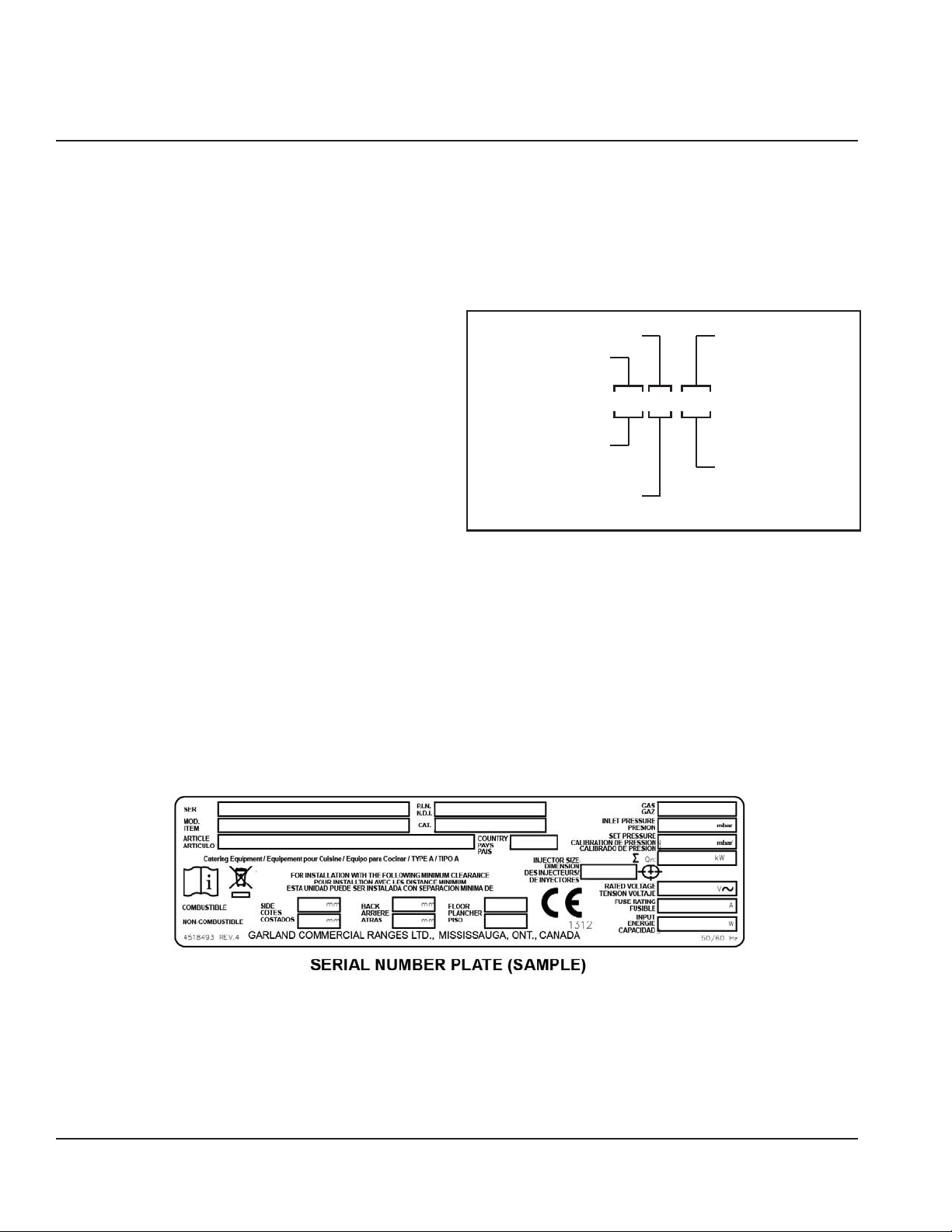
Serial Plate Numbers
The serial plate is affixed to the lower left corner of the
right panel and a serial sticker on front edge of the chassis.
Important information such as the unit’s model number,
serial number, and electrical/gas specifications can be
found on the serial plate.
1P:12” width
2P:24” width
3PX:38” width
10 Part #: GAR_IOM_4600921_Rev5
Page 11

Section 1 General Information
Warranty Statement
This warranty covers defects in material and workmanship under normal use providing that:
a. the equipment has not been accidentally or intentionally damaged, altered or misused.
b. the equipment is properly installed, adjusted, operated and maintained in accordance with national and local
codes and in accordance with the installation instructions provided with this product.
c. the warranty serial number affixed to the appliance by us has not been defaced, obliterated or removed.
d. can acceptable report for any claim under this warranty is supplied to us.
The equipment warranty coverage remains in force for two (2) years, (parts and labor), from the date the equipment is put
into operation.
The Garland Group agrees to repair or replace, at it’s option, any part that proves to be defective in material or
workmanship at no charge for the part or normal labor.
We assume no responsibility for installation, adjustments, diagnosis, or normal maintenance such as: lubrication of springs or
valves. We exclude failures caused by erratic voltage or gas supplies.
We assume no responsibility for travel costs beyond 100 miles round trip, travel other than overland, and overtime
costs of repair.
We exclude broken glass, paint and porcelain nish, surface rust, gasket material, ceramic material, light bulbs and
fuses from normal coverage.
We exclude damage or dysfunction caused by re, ood, and like “Acts of God” that are beyond the control of The
Garland Group.
The Garland Group’s liability on a claim of warranty shall not exceed the price of the material and/or service, which caused the
claim.
This warranty is limited and is in lieu of all other warranties, expressed or implied. The Garland Group, our employees,
or our agents shall not be held liable for any claims of personal injury or consequential damage or loss.
This warranty gives you speci c legal rights, and you may have other rights which vary from state to state.
Shipping Damage Claim Procedure
Please note that the Garland equipment was carefully inspected and packed by skilled personnel before leaving the factory.
The transportation company assumes full responsibility for safe delivery upon acceptance of the equipment. What to do if the
equipment arrives damaged:
1. File a claim immediately regardless of the extent of damage.
2. Be sure to note, “visible loss or damage,” on the freight bill or express receipt and have the person making the delivery
sign it.
3. Concealed loss or damage: if damage is unnoticed until the equipment is unpacked, notify the freight company
immediately, (within 15 days), and le a concealed damage claim.
Part #: GAR_IOM_4600921_Rev5 11
Page 12
General Information Section 1
4
2 3
or
4
5
1
17
7
6
9
12
14
11
16
13
10
15
8
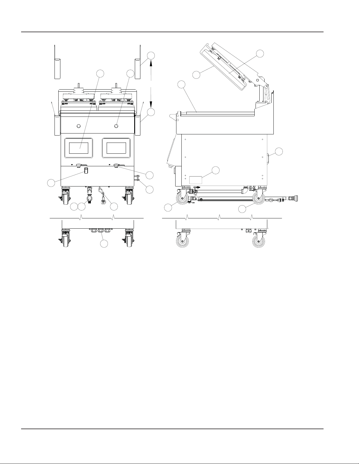
1. On/Off Power Switch.
2. easyToUCH™ Touch sensitive controls for easy operation.
3. Green Push Button.
• press to start cook.
• press and hold to abort.
4. Grease Buckets.
• with straight sides to save space.
• with flared sides to accommodate optional tool
holders.
5. USB Ports - for easyToUCH.
6. Incoming gas manifold (gas models only).
7. Main gas shut off (gas models only). Supply with
optional flexible hose connection assembly.
8. Main Electric Power Cables and Plugs.
9. Restraining device assembly (gas models only)
10. Platen - providing double-side cooking. Each platen can
be controlled separately.
11. Grill Plate - cooking surface with three (3) Independently
controlled heaters per cook zones.
12. Front Casters - height adjustable swivel casters, with
brakes and swivel lock pins.
13. Rear Casters - height adjustable swivel casters and
swivel lock pins (without brakes).
14. Release Material Sheet - non-stick surface for ease of
operation and cleaning.
15. Circuit Breaker(s)
16. Rating Plate location. - Important information such as
the unit’s model number, serial number, and electrical
specifications can be found on the serial plate.
Note: Serial number also can be found in the control in
the “Diagnostic Menu” in the “Revision” screen.
17. Platen connection brackets (optional)
12 Part #: GAR_IOM_4600921_Rev5
Page 13
Section 1 General Information
Items included with the purchase of your new
grill from manufacturer:
1. One Grill 1 platen (gas & electric) includes the following
list;
1 PLATEN
Part # Description Qty
4527294 Release Material Sheet Clips 3
4600722 Release Material Sheet Hanger 1
4600866 Release Material Sheet (box) 1
4600415 Grease Drawer Slide LT 1
4600416 Grease Drawer Slide RT 1
4600411 Grease Drawer Buckets - right side 1
4600418 Grease Drawer Buckets - left side 1
1838701 Platen Levelling Tool 1
4532089 Service Wrench 1
4602107 Garland Grill Start Up Form 1
4600921 Installation Operation Manual 1
NOTE: Quantity may vary according to the model.
2. One Grill 2 platen (gas & electric) includes the following
list;
2 PLATEN
Part # Description Qty
4527294 Release Material Sheet Clips 6
4600722 Release Material Sheet Hanger 2
4600866 Release Material Sheet (box) 1
4600415 Grease Drawer Slide LT 1
4600416 Grease Drawer Slide RT 1
4600411 Grease Drawer Buckets - right side 1
4600418 Grease Drawer Buckets - left side 1
1838701 Platen Levelling Tool 1
4532089 Service Wrench 1
4602107 Garland Grill Start Up Form 1
4600921 Installation Operation Manual 1
NOTE: Quantity may vary according to the model.
3. One Grill 2+1 platen (gas & electric) included the
following list, except countries mentioned
2+1 PLATEN
Part # Description Qty
4527294 Release Material Sheet Clips 9
4600722 Release Material Sheet Hanger 3
4600866 Release Material Sheet (box) 1
4600415 Grease Drawer Slide LT 1
4600416 Grease Drawer Slide RT 1
4600417 Grease Drawer Slide Mid 1
4600411 Grease Drawer Buckets - right side 1
4600427 Grease Drawer Buckets - Middle side 1
4600418 Grease Drawer Buckets - left side 1
4601744 One & Two Hdwe Pkg 1
1838701 Platen Levelling Tool 1
4532089 Service Wrench 1
4602107 Garland Grill Start Up Form 1
4600921 Installation Operation Manual 1
NOTE: Quantity may vary according to the model.
4. One Grill 2+1 platen (gas & electric) single chassis
included the following list, except countries mentioned
2+1 PLATEN SINGLE CHASSIS
Part # Description Qty
4527294 Release Material Sheet Clips 9
4600722 Release Material Sheet Hanger 3
4600866 Release Material Sheet (box) 1
4600415 Grease Drawer Slide LT 1
4600416 Grease Drawer Slide RT 1
4600417 Grease Drawer Slide Middle 1
4600411 Grease Drawer Buckets - right side 1
4600418 Grease Drawer Buckets - left side 1
1838701 Platen Levelling Tool 1
4532089 Service Wrench 1
4602107 Garland Grill Start Up Form 1
4600921 Installation Operation Manual 1
NOTE: Quantity may vary according to the model.
Items NOT INCLUDED from the manufacturer:
1. Any electrical cords needed for application.
2. Any ue box needed for application.
3. Any extra grease buckets or grease rails needed for
application.
THE FOLLOWING INSTALLATION PROCEDURE
CAN BE PERFORMED BY A:
• Factory authorized service center
• An approved installation person approved by Garland.
• Licensed installer contracted by purchaser of grill.
• Contact local Garland Factory Authorized Service Center
for more details.
Part #: GAR_IOM_4600921_Rev5 13
Page 14
General Information Section 1
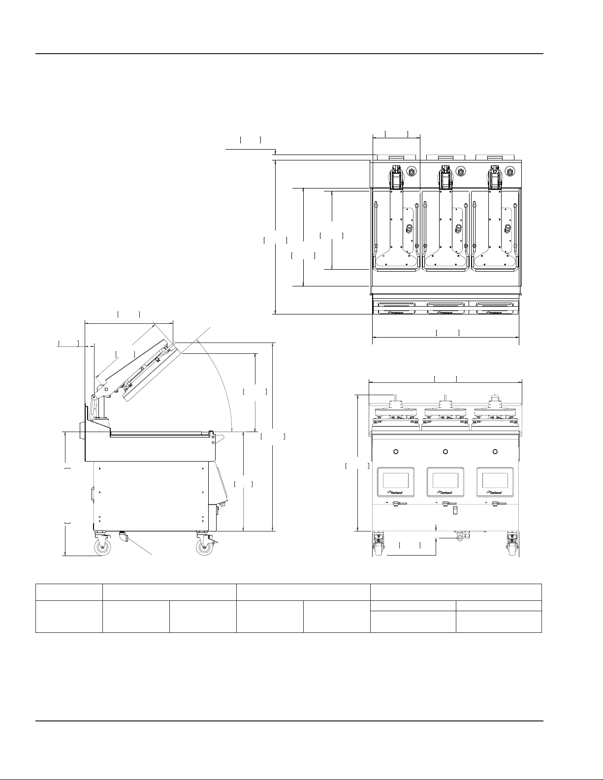
3 Platen Dimensions Specification
Model: M(E/G)-3P
2.170in
55.1mm
540.4mm
19.250in
489mm
MIN
TOP HEATER
1.255in
31.9mm
FOR GAS UNITS ONLY
TOP HEATER
22.000in
558.8mm
17.500in
444.5mm
34.505in
876.4mm
GRILL PLATE
42°
MAX
19.005in
482.7mm
MAX
11.500in
292.1mm
GRILL PLATE
35.750in
908.1mm
TOP VIEW
36.979in
939.3mm
45.528in
1156.4mm
MAX
32.941in
836.7mm
23.978in
609mm
903.6 MAX TO 759.1 MIN
35.574 MAX TO 29.887 MIN
1.726in
43.8mm
GAS CONNECTION
FOR GAS UNITS ONLY
Model Height* Width** Depth
34.5 in - without flue 876 mm - without flue
M(E/G)-3P 32 in 812 mm 36 in 914 mm
35.8in - with flue
(gas models)
* Height not including caster
** Without grease buckets.
909mm - with flue
(gas models)
14 Part #: GAR_IOM_4600921_Rev5
Page 15
Section 1 General Information
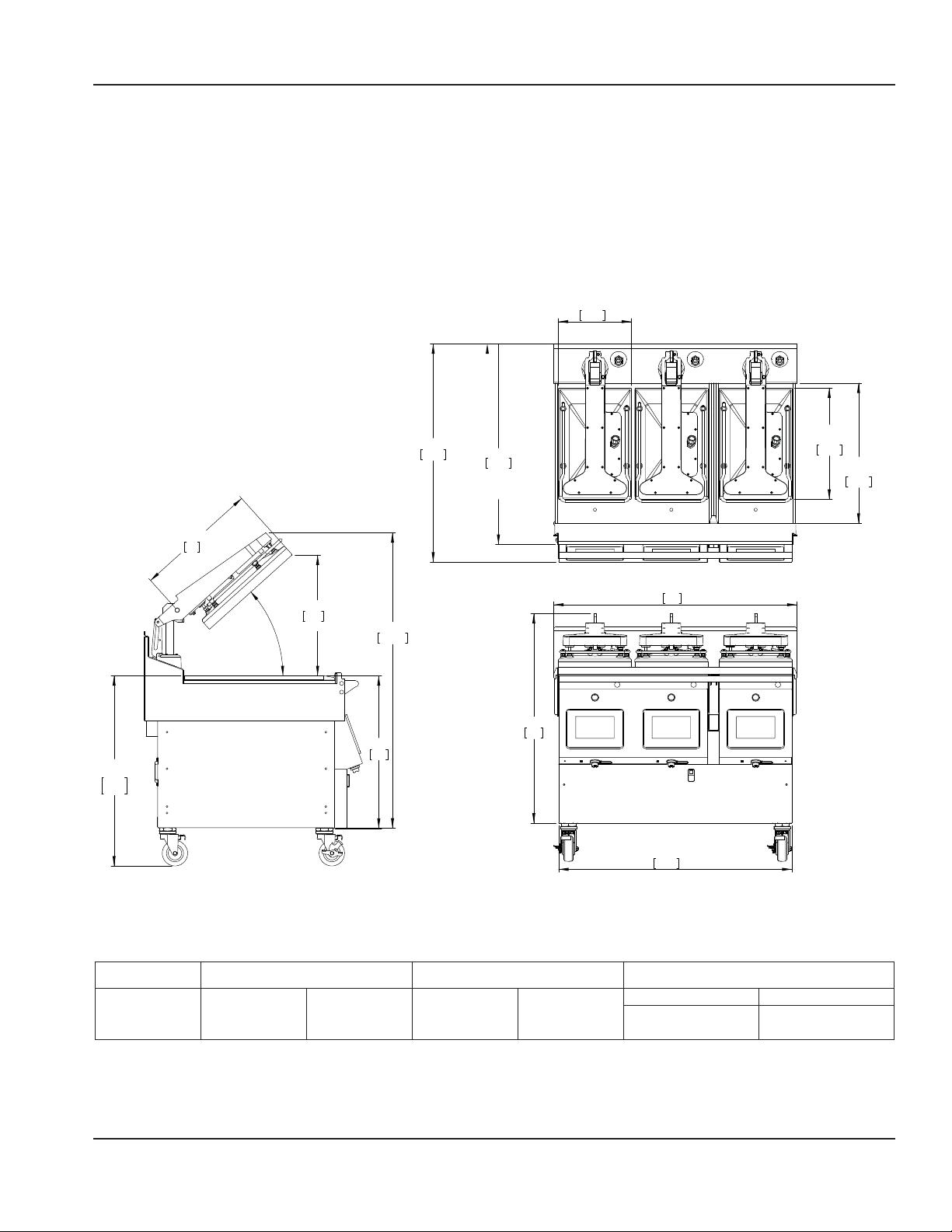
2 + 1 Platen Single Chassis Dimensions Specification
Model: M(E/G)-3PX
TOP HEATER
11.50
292.1
TOP HEATER
34.27
870.5
WITH TOWEL BAR
FRONT PANEL REMOVED
31.51
800.4
&
17.50
444.5
GRILL PLATE
22.00
558.8
19.25
489
38.23
971
36.66
931.1
35.50
29.88
901.7
758.8
42°
MAX.
18.96
481.5
MAX.
23.98
609
46.40
1178.6
32.91
836
Model Height* Width** Depth
876 mm - without flue
909mm - with flue
(gas models)
M(E/G)-3PX 32 in 812 mm 38 in 965.2 mm
34.5 in - without flue
35.8in - with flue
(gas models)
* Height not including caster
** Without grease buckets.
Part #: GAR_IOM_4600921_Rev5 15
Page 16

General Information Section 1
2 Platen Dimensions Specification
Model: M(E/G)-2P
TOP HEATER
1.255in
31.9mm
FOR GAS UNITS ONLY
11.500in
292.1mm
2.170 in
55.1 mm
[903.6 MAX TO 759.1 MIN]
35.574 MAX TO 29.887 MIN
21.276 in
540.4mm
19.250 in
489mm
MIN
22.000in
558.8mm
TOP HEATER
17.500in
444.5mm
32.941in
836.7mm
GRILL PLATE
11.750in
298.5mm
TOP VIEW
24.979in
634.5mm
43.8 mm
1.726 in
FOR GAS UNITS ONLY
34.505in
876.4mm
GRILL PLATE
42°
MAX
19.005 in
482.7mm
MAX
45.528 in
1156.4mm
MAX
23.978 in
609mm
2.551 in
64.8 mm
FOR GAS UNITS ONLY
Admission en gaz
LEFT SIDE VIEW
WITHOUT GREASE BUCKETS
GAS CONNECTION
10.324 in
262.2 mm
FOR GAS UNITS ONLY
9.219 in
234.2 mm
GAS CONNECTION
FOR GAS UNITS ONLY
23.413 in
594.7mm
FRONT VIEW
Model Height* Width** Depth
876 mm - without flue
909mm - with flue
(gas models)
M(E/G)-2P 32 in 812 mm 24 in 610 mm
* Height not including caster
** Without grease buckets.
34.5 in - without flue
35.8in - with flue
(gas models)
16 Part #: GAR_IOM_4600921_Rev5
Page 17
Section 1 General Information
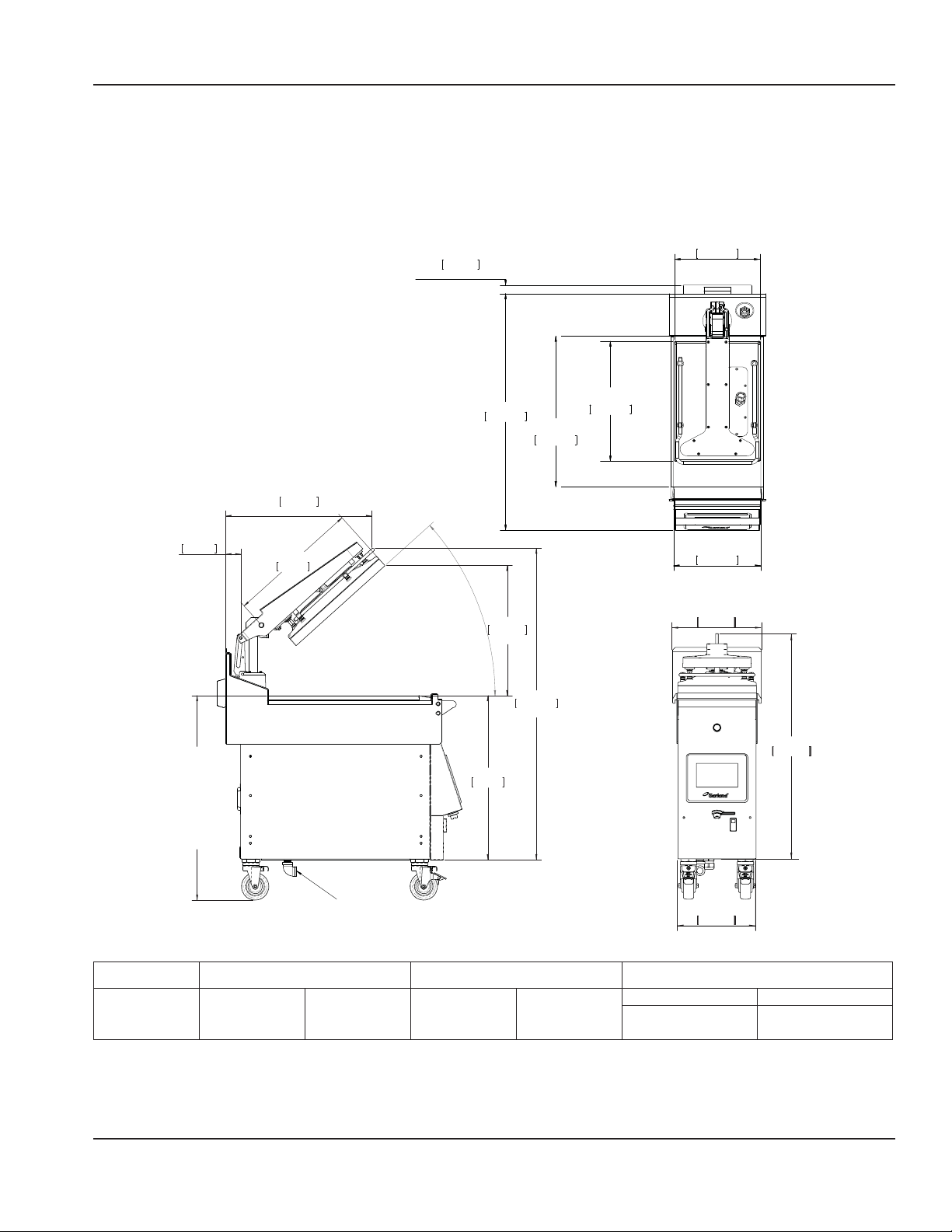
1 Platen Dimensions Specification
Model: M(E/G)-1P
TOP HEATER
11.500in
292.1mm
21.276in
540.4mm
MIN
1.255in
31.9mm
FOR GAS UNITS ONLY
34.505in
876.4mm
GRILL PLATE
22.000in
558.8mm
TOP HEATER
17.500in
444.5mm
2.170in
55.1mm
[903.6 MAX TO 759.1 MIN]
35.574 MAX TO 29.887 MIN
19.250in
489mm
GAS CONNECTION
LEFT SIDE VIEW
WITHOUT GREASE BUCKETS
MAX
23.978in
609mm
42°
19.005in
482.7mm
MAX
1156.4mm
45.528in
MAX
GRILL PLATE
11.750in
298.5mm
TOP VIEW
12.979in
329.7mm
11.413in
289.9mm
FRONT VIEW
Model Height* Width** Depth***
32.941in
836.7mm
876 mm - without flue
909mm - with flue
(gas models)
M(E/G)-1P 32 in 812 mm 13.7 in 305 mm
34.5 in - without flue
35.8in - with flue
(gas models)
* Height not including caster
** Without grease buckets
Part #: GAR_IOM_4600921_Rev5 17
Page 18
General Information Section 1
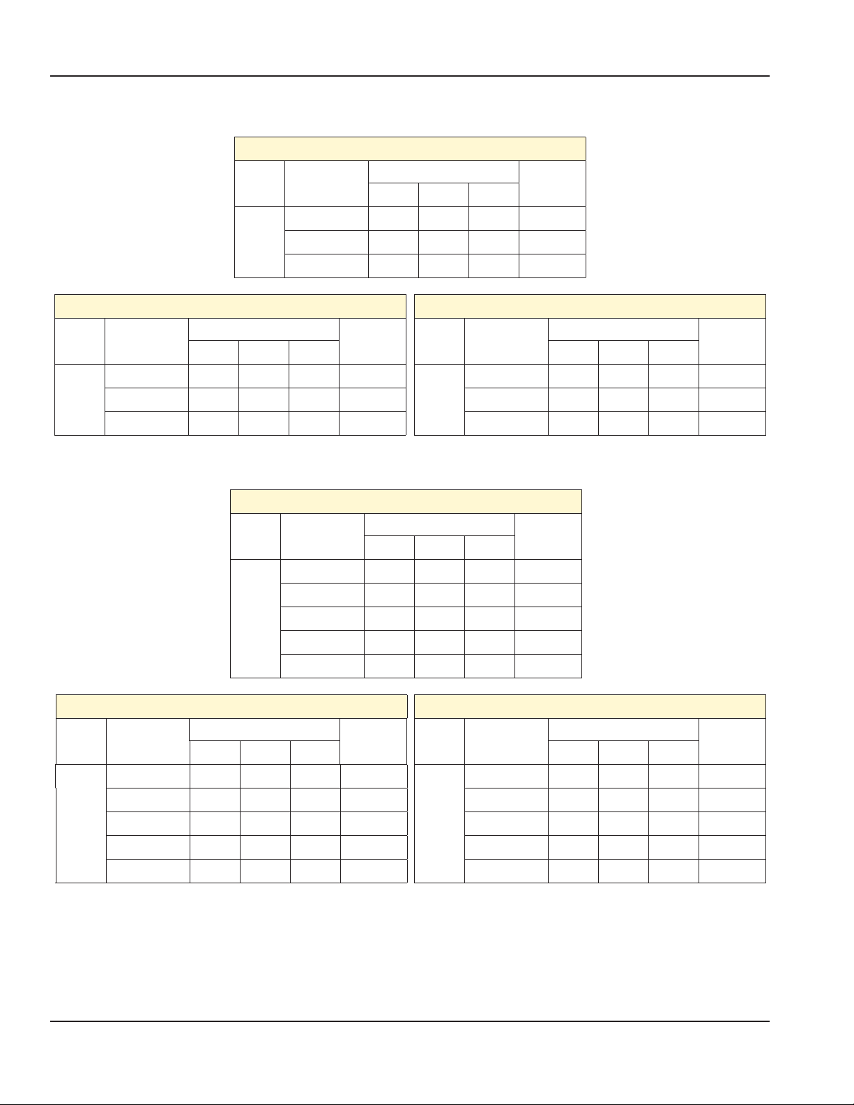
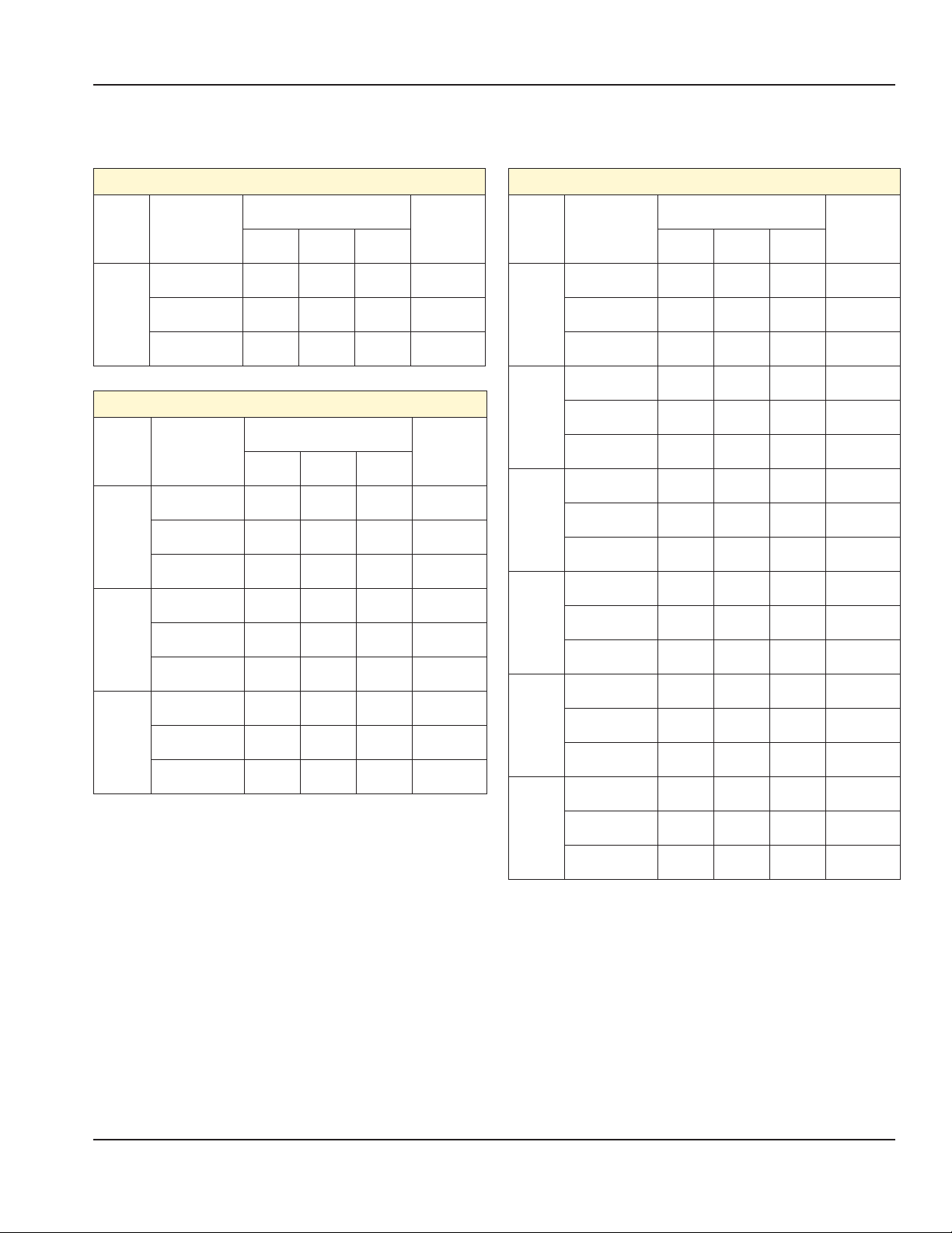
Electrical Input Specification - WYE, (CE - gas models)
MG-1P CE Models (gas)
Model
1
Platen
Volts
3NɎ(WYE)
50/60Hz
220V/380V 12.1 4.7 0.0 3.3
230V/400V 11.3 4.7 0.0 3.4
240V/415V 11.3 4.7 0.0 3.4
Total Current (A)
Power(kW)
L1 L2 L3
MG-2P CE Models (gas)
Model
Volts
3NɎ(WYE)
50/60Hz
Total Current (A)
Power(kW)
L1 L2 L3
220V/380V 4.7 12.1 15.9 6.7
2
Platen
230V/400V 4.7 11.3 15.0 6.7
240V/415V 4.7 11.3 14.8 6.7
Electrical Input Specification - Delta (gas models)
MG-1P Models (gas)
Model
2
Platen
Volts
Model
3Ɏ(DELTA)
50/60Hz
200V 13.6 16.0 4.0 3.4
208V 13.3 15.6 3.9 3.4
1
Platen
220V 12.2 14.3 3.6 3.3
230V 11.8 13.8 3.5 3.4
240V 11.2 13.2 3.3 3.4
MG-2P Models (gas)
Volts
DELTA)
3Ɏ(
50/60Hz
Total Current (A)
Power(kW)
L1 L2 L3
200V 19.9 16.0 27.1 6.8
208V 19.4 15.6 26.5 6.9
220V 17.8 14.3 24.3 6.7
230V 17.2 13.8 23.4 6.7
240V 16.5 13.2 22.4 6.7
Total Current (A)
L1 L2 L3
Model
3
Platen
Model
3
Platen
MG-3P CE Models (gas)
Volts
3NɎ(WYE)
50/60Hz
Total Current (A)
Power(kW)
L1 L2 L3
220V/380V 15.9 15.9 15.9 10.0
230V/400V 15.0 15.0 15.0 10.1
240V/415V 14.8 14.8 14.8 10.1
Power(kW)
MG-3P Models (gas)
Volts
DELTA)
3Ɏ(
50/60Hz
Total Current (A)
Power(kW)
L1 L2 L3
200V 30.5 30.5 30.5 10.2
208V 29.8 29.8 29.8 10.3
220V 27.3 27.3 27.3 10.0
230V 26.3 26.3 26.3 10.1
240V 25.2 25.2 25.2 10.1
18 Part #: GAR_IOM_4600921_Rev5
Page 19
Section 1 General Information
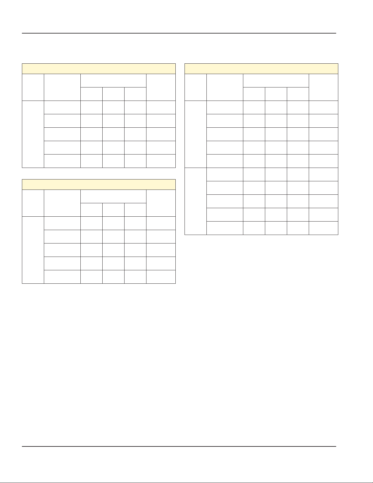
Electrical Input Specification - WYE (CE - electric models)
Model
1
Platen
Model
2P
1 Input
2P
2 Input
Cord 1
2
Platen
2 Input
Cord 2
ME-1P CE Models (electric)
Volts
3NɎ(WYE)
50/60Hz
Total Current (A)
Power(kW)
L1 L2 L3
220V/380V 12.1 15.3 13.6 7.6
230V/400V 11.3 13.8 13.9 7.6
240V/415V 11.3 14.7 13.9 7.6
ME-2P CE Models (electric)
Volts
3NɎ(WYE)
50/60Hz
Total Current (A)
Power(kW)
L1 L2 L3
220V/380V 23.7 24.3 25.7 15.1
230V/400V 22.0 23.2 25.2 15.2
240V/415V 21.3 22.3 25.0 15.1
220V/380V 15.3 13.8 12.2 7.6
230V/400V 15.1 13.8 11.3 7.6
240V/415V 14.7 13.8 11.3 7.6
220V/380V 13.8 12.1 15.5 7.6
230V/400V 13.8 11.3 15.3 7.6
240V/415V 13.8 11.3 14.9 7.6
Model
3PX
1 Input
3PX
2 Input
Cord 1
3PX
2 Input
Cord 2
3PX
3 Input
Cord 1
3PX
3 Input
Cord 2
3PX
3 Input
Cord 3
ME-3PX CE Models (electric)
Volts
3NɎ(WYE)
50/60Hz
Total Current (A)
Power(kW)
L1 L2 L3
220V/380V 35.1 35.1 35.4 22.7
230V/400V 33.2 33.2 33.5 22.8
240V/415V 32.1 32.1 32.4 22.7
220V/380V 15.3 13.8 12.1 7.6
230V/400V 15.1 13.8 11.3 7.6
240V/415V 14.7 13.8 11.3 7.6
220V/380V 24.3 25.5 24.0 15.1
230V/400V 23.2 25.0 22.3 15.2
240V/415V 22.3 24.8 21.6 15.1
220V/380V 15.3 13.8 12.1 7.6
230V/400V 15.1 13.8 11.3 7.6
240V/415V 14.7 13.8 11.3 7.6
220V/380V 12.1 15.3 13.8 7.6
230V/400V 11.3 15.1 13.8 7.6
240V/415V 11.3 14.7 13.8 7.6
220V/380V 13.8 12.1 15.6 7.6
230V/400V 13.8 11.3 15.4 7.6
240V/415V 13.8 11.3 15.0 7.6
Part #: GAR_IOM_4600921_Rev5 19
Page 20
General Information Section 1
Electrical Input Specification - Delta (electic models)
Model
1
Platen
Model
2P
1 Input
ME-1P Models (electric)
Volts
3L (DELTA)
50/60Hz
Total Current (A)
Power(kW)
L1 L2 L3
200V 23.5 24.6 24.4 7.7
208V 23.2 24.3 24.1 7.8
220V 21.5 22.8 22.3 7.6
230V 20.7 22.3 21.4 7.6
240V 20.6 22.0 20.9 7.6
ME-2P Models (electric)
Volts
3L (DELTA)
50/60Hz
Total Current (A)
Power(kW)
L1 L2 L3
200V 46.9 46.5 46.5 15.6
208V 45.7 45.3 45.3 15.6
220V 41.1 41.1 41.1 15.1
230V 38.1 38.8 38.8 15.2
Model
3PX
2 Input
Cord 1
3PX
2 Input
Cord 2
ME-3PX Models (electric)
Volts
3L (DELTA)
50/60Hz
Total Current (A)
Power(kW)
L1 L2 L3
200V 24.5 24.3 23.5 7.7
208V 24.2 24.0 23.2 7.8
220V 22.7 22.2 21.5 7.6
230V 22.2 21.3 20.7 7.6
240V 21.9 20.8 20.2 7.6
200V 46.9 46.6 46.6 15.6
208V 45.7 45.4 45.4 15.6
220V 41.1 41.2 41.2 15.1
230V 38.1 38.9 38.9 15.2
240V 37.0 37.9 37.9 15.1
240V 37.0 37.8 37.8 15.1
20 Part #: GAR_IOM_4600921_Rev5
Page 21

Section 1 General Information
Gas Input Specification
Gas Grills, 1, 2 & 3 Platen North America - all CSA models.
GAS
1
Platen
2
Platen
3
Platen
Input Speci cation - All CE Models.
GAS
GROUP
G20 2.93
G31 2.93
NATURAL GAS
PROPANE 20,000 1.2mm 11.0” WC
NATURAL GAS 40,000 1.5mm 7.0” WC
PROPANE 40,000 1.2mm 11.0” WC
NATURAL GAS 60,000 1.5mm 7.0” WC
PROPANE 60,000 1.2mm 11.0” WC
MAX INPUT NET
PER BURNER kW
MAX INPUT
NET PER
BURNER
BTU/H
12,500
TOTAL INPUT RATING kW
5.86kW - (For ME-1P series)
11.72kW - (For ME-2P series)
5.86kW - (For ME-1P series)
11.72kW - (For ME-2P series)
5.86kW - (For ME-1P series)
11.72kW - (For ME-2P series)
TOTAL INPUT
RATING
BTU/H
20,000 1.5mm 7.0” WC
INJECTOR
SIZE
INJECTOR
SIZE mm
1.5mm
1.5mm
1.2mm
SUPPLY PRESSURE
IN W.C.
BURNER
PRESSURE mbar
10mbar
(4.0” WC)
13.7mbar
(5.5” WC)
10mbar
(4.0” WC)
BURNER MANIFOLD
PRESSURE
IN W.C.
4.0” WC
FAN SPEED
SETTING (RPM)
10,000G25 2.93
For G31 propane gas, the unit has been set at the factory for a 37mbar supply pressure. A factory authorized service
technician must adjust the unit if a 30mbar or 50mbar supply pressure is used.
COUNTRY GAS CATEGORY GAS TYPE SUPPLY PRESSURE (mbar)
AT, CH, CY, CZ, DK, EE, ES, FI, FR, GB, GR, HR, IE, IT, LT,
LU, LV, NL, NO, PT, RO, SE, SI, SK, TR
HU I2H G20 25
DE, LU, PL, RO I2E G20 20
BE I2E(R) G20 20
FR I2E(r) G20/G25 20/25
FR, NL I2L G25 25
RO I2L G25 20
FI, HU,NL, RO I3P G31 30
BE, CH, CZ, ES, FR, GB, GR, HU, IE, IT, LT, NL, PL, PT, SI,
SK, HR
AT, BE, CH, CZ, DE, ES, FR, GB, GR, HU, NL, SK I3P G31 50
Standard elevation is 0 – 4500 feet for all gas types.
Elevation ranges 1 to 3 will only be available for natural gas,
G20, propane gas and G31 (ie: G25, 13A and LPG are not
included).
I2H G20 20
I3P G31 37
Final Elevation Ranges (ft)
Change Within
Each Range (ft)
Standard Elevation 0 to 4500 4500
Elevation Range 1 4501 to 7000 2499
Elevation Range 2 7001 to 9500 2499
Elevation Range 3 9501 to 12000 2499
Part #: GAR_IOM_4600921_Rev5 21
Page 22

STOP! - Follow the instructions below to safely and easily remove unit from packaging skid.
Unit very heavy Personal Protective Equipment (PPE) required.
Removing Grill From Wood Crate.
Tools required.
1. PACKAGING
Section 2
Installation
3. REMOVE AND DISCARD THE TWO (2) WOOD
BLOCKS LOCKING EACH OF THE FRONT CASTER.
NOTE: ENSURE FRONT CASTER BRAKES ARE ON
WHILE BLOCK ARE BEEN REMOVED.
IS DIVIDED IN
TWO PARTS,
CARDBOARD
BOX AND THE
WOOD SKID.
2. REMOVE AND
DISCARD THE
CARDBOARD BOX
COVERING THE UNIT.
Part #: GAR_IOM_4600921_Rev5 21
4. RELEASE THE FRONT CASTER BRAKES AND PUSH
UNIT FORWARD OFF OF THE SKID. ENSURE THAT
THE UNIT ROLLS STRAIGHT AS IT IS BEING MOVED.
Page 23

Installation Section 2
Transporting Grill To Location.
Transporting your new grill to the kitchen requires the
following criteria.
• Plan first before anything else. Lower your risk of
encountering problems during the transport process.
• Understand brake caster mechanism to apply or release
when requires.
• Keep top platen down during transportation.
• Match transportation speed to conditions.
• Turn downhill, not uphill, if stability becomes uncertain
on slope or ramp.
• Push/pull the grill by the towel bar straight even with
the gentle slope.
• Do not push/pull diagonally across it.
• Do not push/pull by conduit or platen arm.
• One (1) platen model is
narrow, take extra care
for slope and ramp. If
slope or ramp is greater
than ±100 there is
potential that the grill
will tip-over, ask for
10
Ý
help and use the proper
techniques transporting
the grill.
Location.
The location selected for the equipment must meet the
following criteria. If any of these criteria are not met, select
another location.
• The location MUST be level and capable of supporting
the weight of the equipment:
→ 3platen - 238.1 kg (525 lbs) approximately.
→ 2platen - 165.6 kg (365 lbs) approximately.
→ 1platen - 154.2 kg (340 lbs) approximately.
• The location MUST be free from and clear of
combustible materials.
• Equipment MUST be level both front to back and side to
side.
• Position the equipment so it will not tip or slide.
• The air temperature must be at least 40°F (4.4°C) must
not exceed 110°F (43.3°C).
• Proper air supply for ventilation is REQUIRED AND
CRITICAL for safe and efficient operation. Refer to
Clearance Requirements chart.
• Do not obstruct the flow of ventilation air. Make sure the
air vents of the equipment are not blocked
• The location must not be near heat-generating (broiler,
dishwashers, etc) equipment or in direct sunlight and
must be protected from weather.
• Do not install the equipment directly over a drain.
Steam rising up out of the drain will adversely affect
operation, air circulation, and damage electrical /
electronic components.
• Do not store anything on top of a unit.
Clearance Requirements
• See section 1, platen dimensions specification for more
details.
Leveling.
Position the unit under the hood and in its normal
operational position to prevent warping of the grill plate &
optimize cooking performance.
• Adjust the unit by turning the casters clockwise to raise
the unit and counterclockwise to lower the unit.
• Adjust the casters until the grill plate is level and at the
proper height.
• Grill must be level front to back, side to side and
diagonally. This leveling must be done with the unit
under the hood and it’s normal operation.
• Tighten the lock nut on each caster tightly against the
bottom of the unit.
• When the unit is in place, lock the front casters to
prevent movement.
• Lock the casters from swiveling to facilitate moving the
unit straight in and out for cleaning.
Exhaust Hood Requirements.
1. Install the equipment under an Exhaust Hood.
2. The exhaust hood must extend over the exhaust ports
and meet the following requirements:
A. The exhaust hood must be sized for the cumulative
ventilation requirements of all the appliances in
the area under the hood.
B. If an existing hood cannot be used, a new one
must be constructed over the equipment.
C. When determining hood size; include clearances.
NOTE: Always turn ON the exhaust hood when the unit is
running to prevent condensation in the unit.
22 Part #: GAR_IOM_4600921_Rev5
Page 24

Section 2 Installation
Ventilation
Hood
25.4
1.00
Min.
Platen
Clearance between Platen and Hood
Positioning.
The unit is very heavy and mechanical assistance may be
required to lift and position the appliance.
The unit is designed to be installed on a smooth and
level floor built to withstand the weight of the fully laden
appliance.
The unit is pre-installed with casters for ease of mobility for
cleaning and servicing. Take proper care to push or pull the
grill and ensure the grill does not tip over.
Casters Adjustment Procedure.
1. Turn the clamshell grill
Green Power Main Switch
OFF. (green light o )
2. Rear and front Casters have a threaded stem to
adjust the level of the grill independently. All casters
have independently swiveling action.
3. All casters are
adjustable.
4. Lock the caster swivel
using the locking pin.
Pull the clip and turn 90
degrees, release pin. (Note:
applying the locking pin in
the lock position will lock
the swivel of the caster
assembly).
5. Carefully raise the unit slightly so that the wheel is
o the ground and no longer bearing unit weight.
6. Loosen caster jam nut by turning it counterclockwise
with a wrench.
Appliances Equipped with Casters.
The unit is shipped with casters installed in place, some
adjustment may be required to level the unit. The front
and rear casters are adjustable, only the front casters have
brakes.
Garland recommends installing restraining chains/cables
from the floor/wall to the rear of the unit. These restraints
limit the mobility of the appliance.
7. Adjust the caster assembly by turning the caster
(swivel locking pin on) counterclockwise to increase the
height or clockwise to decrease the height.
IMPORTANT NOTE
On the caster assembly shown above there is a nut used
to assemble the swivel system - do not use wrench on
this nut. This nut is intended for the caster swiveling
system only.
Part #: GAR_IOM_4600921_Rev5 23
Page 25

Installation Section 2
8. Beware of the red mark in the threaded stem to
indicated the maximum adjustment. Red mark in the
threaded stem portion should not be visible.
Warning: Adjusting above the red mark could cause the
caster to fail & the unit to tip.
Red Mark in Shaft
Should
NOT be Visible
Caster Jam Nuts
FRONT CASTER WITH BRAKE REAR CASTER WITHOUT BRAKE
Tight bolts to secure arm in place
total of four (4) bolts
Stabilizer Arm
ADJUST TO
0.25in
6.4mm
Stabilizer Arm
NOTE: UNDER NO CIRCUMSTANCES SHOULD YOU
REMOVE THE STABILIZER SYSTEM FROM GRILL.
Remove Stainless Steel Plastic Film Cover.
Removing this film is one of the things that must be done
once the Grill is in place. The film covers both internal and
external components (e.g. side panels, grease shield) and
must be removed before turning the grill on.
1. Using a plastic scraper,
wedge the film away from
the stainless steel.
2. Grasp and pull the film
very gently away from the
stainless steel.
PEEL OFF PLASTIC FILM
9. After the grill is completely level, align the caster
wheels straight ahead as shown. Then rotate the locking
pin until is seated fully into the slot and secured. Now,
tighten caster jam nut to secure the caster assembly.
Securing Stabilizer Grill System (1 platen models only).
Stabilizer system will help prevent the grill from tippingover within a range of 0
0
to 100 degrees angle perpendicular
to the front of the unit.
1. Proceed and complete Caster Adjustment Procedure as
mentioned above.
2. Lower the stabilizing arms, (total of four (4) arms
located beside the side panels) until the arms touch the
floor.
3. Raise each arm 0.25” (6.4mm) off the floor and secure
the arm with the bolt on the side of each arm, as shown
below.
Temporary Storage
Garland provides adequate protection under normal
conditions in transit and storage. The grill may need
additional protection if it is stored near salt water, a tropical
area, or other unfavorable conditions. Please contact
Garland immediately if these conditions occur.
Gas Connector Requirements.
• Installation shall be made with the gas connector that
has been supplied with the grill or a similar approved
connector. The quick disconnect fitting and gas shut
off valve must be installed in the direction indicated on
their outer body.
• NOTE: When checking gas pressure, be sure that all
other equipment on the same gas line is on.
• The appliance and its individual shut-off valve must be
disconnected from the gas supply piping system during
any pressure testing of that system pressures in excess
of ½ PSIG (3.45kPa).
• Adequate clearance must be provided for servicing and
proper operation.
• A restraining device must be installed when a flexible
gas hose is used.
24 Part #: GAR_IOM_4600921_Rev5
Page 26

Section 2 Installation
National Codes Requirements.
• The type of gas for which the grill is equipped is
stamped on the serial plate mounted on the lower left
corner of the right panel. Connect a grill to the gas type
stamped on the data plate only.
• The installation must conform to the National Fuel Gas
Code ANSI Z223.1-1998 or latest edition, NFPA No. 54 –
latest edition and National Electrical Code ANSI/NFPA
70-1990 or latest edition and/or local code to assure
safe and efficient operation. In Canada, the installation
must comply with CSA B149.1 and local codes where
applicable.
• In Canada, electrical connection must comply with
applicable sections of the Canadian Electrical Code,
C22.1 - 1990, latest edition, “Safety Standard for
Installation, Part 1” and C22.2- No. O-M 1982 latest
edition.
Installation store responsibilities.
• The installation shall be made with a connector that
complies with the Standard for Connectors for Moveable Gas Appliances, ANSI Z21.69/CSA 6.16, and quickdisconnect device that complies with the Standard for
Quick Disconnect Devices for Use with Gas Fuel, ANSI
Z21.41/CSA 6.9.
• The front Casters on the appliance are equipped with
brakes to limit the movement of the appliance without
placing any strain on the connector or quick disconnect
device or its associated piping.
• Please be aware: required restraint is attached to a
bracket, (which is located on the front of the grill,
underneath, closest to the gas connection) and if
disconnection of the restraint is necessary, be sure
to reconnect the device after the appliance has been
returned to its original position.
• Not intended to be installed adjacent to combustible
walls or on combustible floors.
• Ensure grill has been installed by a competent trained
installation person.
• Ensure store readiness of utilities, product & personnel.
• Contacting your local Garland Factory Authorized
Service Center for a startup date.
• Participate in the startup to ensure a successful startup
and familiarity with the grill.
• Conduct training with your crew personnel to ensure
maximum utilization of the grill. Once the installation
is complete as per the procedures below, a factory
authorized service company MUST startup the grill
according to Garland Commercial Ranges startup
standards.
Restraining device installation Procedure.
1. Shutoff main gas line valve and disconnect the quickdisconnect gas line device before the following
installation .
2. Attach the bracket to a stud in the wall.
3. Locate the area in the
frame on front of the grill
underneath, to place the
eye-bolt. Closest to the gas
connection
4. For model one (1) platen grill gas. Discard nylon
lock nut of the eye-bolt and screw it underneath
of the front panel above the gas line (Figure
A), tighten eye-bolt jam nut to secure it in place.
5. For model two & three (2&3) platen grill gas. Slide
the eye-bolt through the hole and place the nylon
lock nut on the inside frame and tighten securely
(Figure B).
attached to the wall
spring loaded
hook
STUD
BLOCKING SECURE
TO CONCRETE WALL
OR STUD
RESTRAINING CABLE
FRONT CASTER WITH
BRAKE TO SECURE GRILL
loop
appliance
eye-bolt
• “Adequate clearance must be provide for air opening
into the combustion chamber, and for proper servicing”
Part #: GAR_IOM_4600921_Rev5 25
Page 27

Installation Section 2
6. Attach one of the spring-loaded hook to the bracket
on the wall and the other end to the eye-bolt (grill).
adjust the proper distance of the cable 1 and tight
both clamps 2 to secure the both cables
7. Test straining cable by moving the grill, movement of
the grill must not place any strain on the connector or
quick disconnect device or its associated piping.
Figure A - one (1) platen
Figure B - two & three (1&2) platen
“Desi Pak” bags from the grill.
• Desi Pak bags are only intended to be left inside the
grill during shipment and equipment storage. Desi
Pak are designed to protect the electronic
components by controlling humidity levels
within the equipment.
• Garland highly recommends these bags
remain in the equipment while the grills are
in storage or not in operation
Removing “Desi Pak” bags from the grill.
1. Turn the clamshell grill
Green Power Main Switch OFF
(green light o )
.
2. Using a 5/16” socket, remove the 5 screws from the
top rear panel. Store screws in a safe place.
3. Using a 5/16” socket, remove the 4 screws from the
bottom rear panel. Store screws in a safe place, be very
careful with the wires and connectors. Remove the “Desi
Pak” bag and discard.
4. Reinstall covers and tighten the screws.
Gas Connections, and Pipe Sizing.
• The size of the gas line is very important. If the line
is too small, the gas pressure at the burner manifold
will be low. This will cause slow recovery and delayed
ignition. The incoming gas pressure line should be a
minimum of 1-1/2”. A 2+1 single chassis platen grill
requires a 3/4” connection and a 1platen grill requires a
1/2” connection. The 2platen grill can have either a 1/2”
or 3/4” connection.
• Before connecting new pipe the pipe must be blown
out to dispose of any foreign particles. These particles
will cause improper operation.
• When using thread compound, use small amounts on
male threads only. Use a compound that is not affected
by the chemical action of LP gases. Avoid applying
compound to the first two threads to prevent clogging
of the burner orifices and control valve.
• Have the installer check all gas plumbing with a soap
solution for leaks. DO NOT USE matches, candles or
other ignition sources in checking for leaks.
• Check the data plate to determine the proper type of
gas before connecting the quick disconnect or piping
from the building gas supply.
• An incoming gas pressure test nipple is provided on the
incoming gas manifold for pressure checks.
• Minimum incoming gas pressure for Natural Gas is 6”
W.C. Maximum incoming gas pressure for Natural Gas is
14” W.C.
• Minimum incoming gas pressure for Propane is 10” W.C.
Maximum incoming gas pressure for Propane is 23” W.C.
• Burner operating gas pressure can be checked at the
outlet side of the gas valve at the pressure test point.
• Refer to “Gas Input Specification Chart” for correct
burner manifold pressure based on gas type.
• To adjust the burner pressure;
a. remove the sealing screw from the pressure spigot
on the outlet side of the gas valve and the connect a
manometer.
b. remove the sealing cap on the gas valve regulator
c. turn on both burners in that lane and set the pressure
26 Part #: GAR_IOM_4600921_Rev5
Page 28

Section 2 Installation
by turning the regulator screw.
d. turn off the grill, remove themanometer and re-fit the
sealing screw on the pressure spigot and regulator.
e. test those connection for leaks.
f. these procedure must be done by qualify technician
only.
• Gas pressures should be checked by the local Gas
Company or an authorized service agency only.
• Test all piping and connections for gas leaks. A rich soap
solution should be used for this purpose. Never use a
flame. If inside unit, protect electronic components/
boards before leak tesing with soap solution.
• The appliance must be isolated from the gas supply
piping system by closing its individual manual
shutoff valve during any pressure testing of the gas
supply piping system at test pressures equal to or
greater than ½ psi (3.5 kPa).
• If included, install the quick-disconnect gas hose to
the inlet fitting on the underside of the grill. Remove
dust cap from the male coupler and snap the quickdisconnect fitting on the gas hose assembly onto the
male coupler.
UNDERNEATH GRILL QUICK-DISCONNECT
FLEXIBLE GAS HOSE
Snorkel Box Installation
• Remove snorkel box and screws from carton.
• Place the snorkel box in place as shown in picture
below.
• Using a 5/16” socket, install the 2 screws in place and
tighten screws.
• A quantity of 2 snorkel boxes should be installed per
lane. Picture below shows a 1 platen grill.
• Follow the next upper rear flue panel installation
instruction if required.
SNORKEL BOX
TO GAS
SUPPLY
FACTORY
INSTALLED
GAS INLET
MALE COUPLER
ALREADY INSTALLED
GAS
FLOW
• Ensure the sleeve snaps fully forward against the
retaining ring.
• With the manual shut-off valve closed, and gas hose
assembly disconnected from the unit install the
other end of the hose to the gas supply.
• Attached Shut-Off sticker as shown below:
Electrical Connection
Warning
Disconnect power supply before starting this procedure.
• All electrically operated appliances must be electrically
grounded in accordance with local codes; or in the
absence of local codes, with the latest edition of
National Wiring Regulations. A wiring diagram is located
on the rear panel of the grill. See rating serial plate
mounted on the lower left corner of the right panel for
proper voltages.
• The entry point for the electrical connection is located
on the rear of the appliance.
• Do not cut or remove the grounding prong from the
plug.
• Adequate means of disconnection of the supply must
be provided.
• It is recommended to allow enough slack on the
electrical cord to allow the appliance to be pulled out
for proper cleaning and maintenance.
Part #: GAR_IOM_4600921_Rev5 27
Page 29

Installation Section 2
Mennekes 7 Pins Option.
Inlet Pins Intended Load Connected to
Grill and Platen Heaters
Mennekes
7 Pins
16A Socket for 1P units
32A Socket for 2P units
MENNEKES 7 PIN OPTION
1,2,3,4,GND
3N~ 380/400/415V
Refer to load table for amperages
50/60Hz
5,6
Interlock Contactor coil
7A . 415VAC Max.
MENNEKES INLET: 7 POLES 6h 3N~ 380/400/415V 50/60Hz
L3-POWER TERMINAL BLOCK
Power Terminal Block
L1,L2,L3,N, GND
Control Terminal Block
BLK & RED
N-POWER TERMINAL BLOCK
5-CONTROL TERMINAL BLOCK RED
6-CONTROL TERMINAL BLOCK BLK
3
4
2
6
15
L2-POWER TERMINAL BLOCK
L1-POWER TERMINAL BLOCK
E -POWER TERMINAL BLOCK
28 Part #: GAR_IOM_4600921_Rev5
Page 30

Section 2 Installation
Flue Upper Rear Panel Install Instruction.
Install flue box to the back of grill for all gas grill models
only (if required).
1
3
ue box
assembly
griddle
rear
backsplash
Place hemmed ange of ue box over top
edge of griddle rear backsplash
2
upper
rear
panel
Remove the ue assembly
from the accessory box
Loosen three screws, two turns
counterclockwise
4
Re-tighten lower three screws
Installation completed
Part #: GAR_IOM_4600921_Rev5 29
Page 31

Installation Section 2
One & Two Platen Connections Procedure.
The feature clamshell 1 & 2 platen grill have the option
to attach them together. The important thing here is to
connect on brackets and secure them to form one grill. A
single grill could be attached to the right or left side of the
double grill to suit you own preference.
• Make sure you read the instruction through
completely before you start to put the unit together.
• Bracket are located on the lower part of the side
panel, bracket could be located on right or on the
left panel, according to configuration selected.
Picture below shown the bracket located on the
right side panel of the single unit.
• Below shown the parts need it to connect two grills
together (parts not to scale).
• Connect the bracket as per instruction below. Do
not place you hand or your finger while making the
connection.
• Place the pin “a” into the
brackets “b” , then place the
cotter pin in place.
• Place near bracket “c” to
bracket “b” and slide it through the pin.
30 Part #: GAR_IOM_4600921_Rev5
Page 32

Section 2 Installation
• Make sure to make the front & back bracket
connection simultaneously.
• Insert the grease drawer slide between the grills,
this bracket is set to lock the grills together. Tilt the
bracket
• Tilt the front bracket down. Insert the front bracket
slot into the pin. Use a flashlight to ensure the
connection of both front pins are all way in.
• Slide in grease drawer all the way up to the end.
Connection Brackets Installation:
• Braket with pin get install to the two platen grill, see
diagram below.
• Insert the grease drawer slide between the grills,
this bracket is set to lock the grills together. Tilt the
bracket
• Tilt the front bracket up. Insert the rear bracket
slot into the pin. Use a flashlight to ensure the
connection of both pins are all way in.
• Place brackets side-by-side to see if the holes are not
line up through the same center line, otherwise turn
the bracket with pin 180 degree.
Placing bracket
C
L
C
L
side-by-side, holes
line up through the
same center line.
Incorrect
C
L
C
L
Correct
Safety List to Remember:
1. Do not move the grill with the platen up.
2. Keep fingers/hand away from brackets and between
the grills.
3. Manipulate the grill through the towel bar only.
Placing bracket
side-by-side, holes
does not line up
through the same
center line.
Part #: GAR_IOM_4600921_Rev5 31
Page 33

Installation Section 2
Install Release Material Sheets
(Rear Loop Option).
In order to achieve proper cooking performance, ensure
that the release material sheet is installed properly to the
platen.
List of Material:
1. Release Material Locking Clips, use three (3) per platen
2. Release Material Rear Hook, use one (1) per platen
3. Release Material Sheet, use one (1) per platen
Platen Release Material Sheet Installation Procedure
1. Raise top platen, by
pressing the green
button.
2. Slide release material
hook through the
hemmed (tube) end
of the release material
sheet.
Release Material
Rear Hook
Release
Material
Locking
Clips
Release Material
Sheet
Release
material
hook
Release
material
sheet
4. Gently pull the release
material sheet towards
the front platen and then
wrap the sheet around
the front of platen and
over the U bar, while
holding the front end
sheet, place the locking
clip over the sheet and
press into the rod.
5. Repeat the above
procedure for the other
two sides of release
material sheet.
6. Check alignment and
tightness of release
material against the
upper platen. Make
adjustment if necessary.
Release Material should be replaced when:
• Product sticks to release material.
• Carbon builds up.
• A tear in the release material appears.
• Release material coating is worn off sheet.
3. Hook the release material hook bar onto the anchor
located at the rear of the platen.
ANCHOR
(REAR TOP PLATEN)
TOP PLATEN
MATERIAL SHEET
32 Part #: GAR_IOM_4600921_Rev5
Page 34

Section 2 Installation
,
Startup Procedure.
This Garland 1, 2 & 3-platen grill comes with a factory
startup at no additional charge. A startup is required to take
place BEFORE the unit is put into operation. It is the
end-user responsibility to schedule the startup with their
local Factory Authorized Service Agent.
A factory startup is a comprehensive grill check in which
a factory certified technician will document all final
settings programmed in the controller once various other
performance checks are complete. The estimated time to
complete a startup is approximately 1.5 – 2 hours. Please
GARLAND CLAMSHELL GRILL START – UP FORM
ELECTRIC OR COMBINATION GAS / ELECTRIC
McDonald’s ___________ Certification ID # __________ Store # _____________ Model
Address ____________________________ City ___________________________
State / Province _____________ Zip Code _________ Serial# _________________________________ Start Up Date ____________
ƑUnited States Ƒ Canada ƑInternational (List Country) ___________________ Telephone # _______________________
Actual Gas Type ____________
Matches Rating Plate? YES NO
1. To avoid personal injury or property damage, Check for Gas Leaks through the entire gas line.
2. Make sure the breaker is turned to the “ON” position.
3. Ensure equipment restraint devices are installed correctly according to local codes (Gas & Electric). Note: part supplied by others.
4. Verify, power cord has a strain relief attached from power supply cord to grill unit.
5. Ensure grill is installed in the proper type of Gas Exhaust Hood with the proper air draw.
6. Ensure flue restrictors are fully opened or removed. Flue Box Supplied by KES
Flue Restrictors located inside exhaust hood
7. Verify serial number (serial plate located on side panel) of the grill, and record the installation date of the grill in the controller,
under settings.
8. Ensure bottom grill plate is leveled side to side / front to back / diagonally, in location, under hood. Adjust casters to attain level.
9. REMOVE GRILL FROM UNDER THE HOOD. Turn power switch ON, displays are active. All platen raises automatically?
10. Lower and raise Upper Platen (green button) and ensure movement is smooth and continuous. Grease shafts accordingly with a
FOOD GRADE LUBRICANT.
11. If upper platen elevation requires lowered to allow for clearance of hood, adjust hood height to 1” below hood. Refer to
Operations & Installation manual for platen heights.
12. Ensure grill enters preheat, counts down and upper platen auto calibrates while at temperature.
13. Close valve handle and verify the unit tries to ignite three (3) times and then locks out because of Ignition Failure?
14. GAS PRESSURE CHECKS (if applicable): (Note 1: Center should not be fill if MG-2P) (Note 2: Left & Right should not be fill if MG-1P )
Rated Incoming Pressure
Rated Burner Pressure Natural Gas
Propane Gas
15. Check micro amps reading. Should be 1.4 uA or greater per zone.
Actual Mic ro Amp Readings: Left Front: . Left Back:
Actual Micro Amp Readings: Middle Front: . Middle Back:
Actua l Micro Amp Readings: Right Front: . Right Back:
16. Select menu item “10:1 – CLAM” icon. Verify set temperature is reached press thermometer icon.
17. Initiate cook cycle by pushing the GREEN BUTTON or checkmark on screen. Platen lowers, and timing cycle begins.
18. Ensure the stores pyrometer is accurate and calibrated using the ice bath method.
19. Perform PROBE CALIBRATION.
20. Perform Platen Leveling procedure
21. Ensure grill performs successful Auto Calibration
22. Lock down all caps. Ensure that the lock nuts do not turn any of the adjuster nuts when tightening.
23. Assist or obtain assistance with store personnel for Beef/Chicken Integrity Testing, testing product 10:1, 4:1, Angus, Grill
Chicken until desired internal product temperatures are met and record cook time (Product cook times chart below).
Problems / Special Circumstances / Damage:
Name: _________________________________________________________ Name: __________________________________________________________________
Service Agency: _________________________________________________
Sub Agent: (If Applicable) _________________________________________
Have you trained store personnel on the
operation of the grill?
Are you a factory certified technician?
Date of Certification (MM/DD/YY)
Located on Certification Sticker (TICK ONE)
Gas Type Electric / 3-phase Record Amps Per Line Each Contactor
NOTE2: RIGHT(R) & LEFT(L) PLATEN should not be checked if ME-1P / MG-1P
Ƒ Natural Gas: 6 – 14” W.C. / Ƒ Propane / Butane Gas: 11 – 14” W.C. Actual Incoming _______” W.C.
SAMPLE
LEFT
10:1 Tested Auto Mode Ƒ OK
4:1
GRILL CHICKEN
Cook one (1) run
Submitted by: Accepted by:
Visit our https://clamshell.garland-group.com for Literature & Documentation
White Copy – Factory Yellow Copy – Service Agency Pink Copy – Customer
Actual Input ____________V /______Hz
Ŀ 208 VAC Ŀ 380 VAC
Ŀ 220 VAC Ŀ 400 VAC Ŀ 60 Hz
Ŀ 230 VAC Ŀ 415 VAC Ŀ 50 Hz
Ŀ 240 VAC
NOTE1: CENTER(C) PLATEN should not be checked if ME-2P / MG-2P
INSPECTION / OPERATIONAL CHECK
Ƒ 4.0” W.C. Actual Left ________ Center ________ Right ________
Ƒ 4.0” W.C. Actual Left ________ Center ________ Right _________
Product Cook Times Beef Integrity Product
YES / NO
YES / NO
CENTER
(If Applicable)
keep in mind this estimated time when scheduling the
startup. After hours or overtime is not covered under
warranty and will be billed at a charge which is the
difference between the Garland Reimbursement rate and
the Factory Authorized Service Centers overtime charges.
A factory startup is necessary to start the warranty period.
The Authorized Service Center is required to complete
the paperwork during the startup process, and send it
to Garland Commercial Ranges for reimbursement. At the
time of receipt, Garland will start the warranty period.
RIGHT
(If Applicable)
Have you been adequately informed of the operation of the grill, its uses and its general
operation? Ƒ YES | Ƒ NO – Indicate comments __________________________________
________________________________________________________________________
________________________________________________________________________
________________________________________________________________________
Ƒ MG-1P, Ƒ ME-1P
Ƒ MG-2P, Ƒ ME-2P
Ƒ MG-3PX
( MM / DD / YYYY )
Left
Line 1
Line 2
Line 3
(Applicable to 1 platen)
Ƒ PASSED – NO GAS LEAKS
Ƒ OK
Ƒ OK
Ƒ YES / Ƒ NO
Ƒ OK
Ƒ OK
Ƒ OK
Ƒ OK
Ƒ OK
Ƒ OK | C Ƒ OK | R Ƒ OK
L
L
Ƒ OK | C Ƒ OK | R Ƒ OK
Ƒ OK | C Ƒ OK | R Ƒ OK
L
Ƒ OK | C Ƒ OK | R Ƒ OK
L
Ƒ OK | C Ƒ OK | R Ƒ OK
L
Ƒ OK | C Ƒ OK | R Ƒ OK
L
Ƒ OK | C Ƒ OK | R Ƒ OK
L
Ƒ OK
Ƒ OK | C Ƒ OK | R Ƒ OK
L
Ƒ OK | C Ƒ OK | R Ƒ OK
L
Ƒ OK | C Ƒ OK | R Ƒ OK
L
Ƒ OK | C Ƒ OK | R Ƒ OK
L
Ƒ OK | C Ƒ OK | R Ƒ OK
L
Manual Mode Ƒ OK
Ƒ ME-3PX
Center
Right
P/N 4602107 (3 Mar 17)
Part #: GAR_IOM_4600921_Rev5 33
Page 35

Section 3
Operation
NOTE: Do not operate the unit without reading and
understanding the safety requirements. Refer to the safety
section at the front of this manual.
Sequence of Operation
After turning the power switch to “I” or ON position, the
grill will go through initialization. If the upper platens are in
the lowered position they will return to their raised upper
position. This movement takes approximately 8 seconds.
The upper platen is lowered automatically, following the
initiation of the cooking cycle, and the upper platen is
raised automatically upon completion of the cooking cycle.
Warning
With two sided cooking, the area between the upper
platen and the griddle plate should be regarded as a
“danger zone.” During two sided cooking the operator
must not be within this danger zone.
In two sided cooking, the upper platen remains in the
lowered position by nature of its own weight. It is not
locked down. It can be raised by lifting up on the handle on
the front of the platen. Under no circumstances, other than
safety, should the platen be manually opened more than
the normal open position.
Wrong
Platen
Position
Normal Open
Normal
Platen
Position
Close
Caution
Do Not
Push
Platen
Lifting the platen manually over the normal open position
is very dangerous; this can cause premature failure of the
electrical flex steel conduit and the lifting mechanism.
What buttons do;
1. Power Switch turns the
grill OFF or ON.
2. Green button:
• press to start cook.
• press and hold to abort
Green light
indicates
that the
Grill power
is “ON”
34 Part #: GAR_IOM_4600921_Rev5
Page 36

Section 3 Operation
easyToUCH™ Controller
HOME SCREEN, RECIPE SELECTOR SCREEN & ICONS
The easyToUCH™ HOME and RECIPE SELECTOR screens
are the most frequently used screens. Many of the icons
described below also appear on other easyToUCH™ cooking
and settings screens.
Home Screen
Recipe Selector Screen
PRESS & GO – is used to initiate preheat and
cook on the grill.
MENUS – is used to activate, add, edit and
delete Menus from the library. A Menu is a
collection of cook recipes. Password protected.
RECIPES – is used to add, edit and delete
Recipes from the library. A Recipe consists of the
cooking times, temperatures and platen gap for
preparing a food item. Password protected.
SETTINGS – is used to change certain settings,
such as date, time and volume. Password
protected.
DIAGNOSTICS – allows access to the
diagnostics screens. Password protected.
COOK CYCLE CHANGE – is used to adjust a
recipe’s cook time or platen gap, if required to
achieve food safety and quality standards.
TEMPERATURE – is used to view the
temperature settings and actual temperature in
each zone.
CLEAN MODE – is used to put the grill into
Clean mode, and heat or cool the grill to the
required temp. When the grill is set to enforce
the cleaning schedule, using the Clean mode
resets the cleaning counter.
LOCK – is used to temporarily lock the touch
screen for fifteen (15) seconds. This prevents
buttons being pressed accidentally when wiping
the screen.
LANGUAGE – is used to change the language of
on-screen prompts. Only available for languages
that have been pre-loaded.
HOME – returns to the Home screen, the
launching point for cooking settings and
programming modes. When the home screen
is showing, the heaters are OFF (shown at top
right corner).
SLEEP – is used to enter Sleep mode. In Sleep
mode, the grill maintains the platen lowered to
conserve energy during periods of inactivity.
NOTE: The easyToUCH™ screen display, layout and icons
shown herein are for guidance purposes only and are not
intended to be an exact representation of those displayed
on the grill.
Part #: GAR_IOM_4600921_Rev5 35
Page 37

Operation Section 3
ON SCREEN WARNINGS AND ALERTS MESSAGES
Too Cool/Too Hot - If the grill temperature is too cool to
properly cook a recipe, a “Too Cool to Cook” message
appears. The grill will not allow the cook cycle to start
until it has heated to the minimum required starting
temperature.
Similarly, if the grill is too hot, a “Too Hot to Cook” message
appears and a cook cycle can not start until the grill cools.
In either case, another recipe can be selected. If the grill is
at the right temperature to cook the newly selected recipe,
the message disappears and cooking can start immediately.
OPERATIONS OVERVIEW
The grill operates in several modes:
• Press & Go mode to preheat and to cook.
• Sleep mode to conserve energy.
• Clean mode to attain temperature for cleaning and
reset cleaning reminders.
All operating modes are accessible using the easyToUCH™
screen. All modes except for Sleep can be selected from the
Home screen. Clean mode can be selected from the Home
screen or from the Press & Go screen.
Press & Go Mode
Press & Go mode is used to initiate preheat and
cook on the grill.
Menus and Recipes
Multiple menus can be set up, each using different set
point and containing different or share recipes. The
recipes stored by the grill contain the cooking profiles
(times, temperatures, prompts and platen gap) for various
products. Menus and recipes can be added, edited and
deleted from the library. Cook time and/or platen gap may
be changed for each recipe as well, depending on the grill
set up.
Sleep Mode
Sleep mode lowers the platen to conserve
energy during periods of inactivity, keeping it
ready to start a cook cycle. When in Sleep
mode, the grill will maintain the current
temperatures.
Automatic Sleep Mode
The grill can be configured to enter Sleep mode
automatically after a period of inactivity. Refer to
easyToUCH™ Diagnostics & Settings Menu.
Manual Sleep Activation
User can also manually activate the Sleep mode when in
Press & Go.
Clean Mode
Clean mode has two functions: brings the grill
to the appropriate temperature for cleaning
and it resets the cleaning counter.
If a cleaning temperature has been set, Clean
mode will bring the grill to the set temperature prior to
starting the cycle. A cleaning temperature may be specified
if required by the chemicals used for cleaning.
Putting the grill into Clean mode before cleaning the grill
updates the “Last cleaned” date and resets the cleaning
reminder prompts, if these are enabled.
Preheat
The grill will preheat after a menu has been selected
in Press & Go mode. If multiple menus have been set
up, select the appropriate menu first to ensure the grill
preheats to the correct temperature, otherwise the menu
is automatically selected after first ten (10) seconds for the
last menu.
36 Part #: GAR_IOM_4600921_Rev5
Page 38

Section 3 Operation
easyTOUCH™ Procedures
START UP & INSERT INSTALLATION DATE
1. Switch the grill on
using the main
power switch.
2. The easyToUCH™
screen illuminates
with the display
briefly showing the
software version.
3. HOME screen
appears. Select
Settings.
4. Select FACTORY
SETTINGS.
5. Select INSTALL
DATE.
software version xxxx.xxx.xxx
licence agreement xxxx.xxxx
patent number xxxxxxx
country of origin xxxxxx
developed by company name
.....and other startup information
Green light
indicates
that the
Grill power
8. Install date
completed. A
window let you
know that a save is
taking place.
is “ON”
PREHEAT
1. HOME screen
appears. Select
Press & Go. A
choice of cook
menus is displayed.
2. MENU SELECTOR
screen appears.
Choose the desired
menu.
If only one menu
is available, grill
will select it and
quickly transition
to preheat.
3. Preheating starts,
using the set
temperatures
from the selected
menu and the
preheat progress is
displayed.
NOTE: To cancel preheating and exit to the Home Screen
press . Select at the top to switch menus
during preheat.
6. Type the date of
installation and
then press the
check-mark to
save.
Following preheat the grill enters a soak period, allowing
the temperature to stabilize throughout the upper platen.
After soak, grill will start auto-gap & auto-leveling option
feature.
4. The unit is ready
to use when the
platen opens and
7. Verify the
installation date
the Recipe Selector
screen is displayed.
and the serial
number then press
the check-mark to
save.
Part #: GAR_IOM_4600921_Rev5 37
Page 39

Operation Section 3
COOK A RECIPE
1. On the RECIPE
SELECTOR screen,
select a recipe to
cook.
Lay product on
the grill and press
START or press the
Green Push Button
to begin the cycle.
2. The screen displays
a progress ring and
the remaining cook
time.
3. An audible warning sounds prior to the end of the
cook cycle. When the cook cycle has finished, the
platen lifts. Press the check mark or the Green button
to clear the message.
4. The recipe
selection screen
reappears.
5. Selecting
during the cooking
stops the cook
cycle. The cycle can
also be aborted by
pushing the Green
push-button for
two seconds.
CHECK TEMPERATURES
The temperature screen shows the actual and the set point
temperatures at each thermocouple.
1. The temperature
screen can be
displayed by
pressing the icon
in the top right
corner when
cooking, cleaning,
or preheating.
2. Press the Back
Arrow or the Check
Mark to return
to the previous
screen.
CANCELING A COOK CYCLE
1. Canceling the
cook cycle raises
the platen,
and displays
a “DISCARD
PRODUCT”
message. Press the
check mark to clear
the message.
NOTE: If the wrong recipe was selected, change the recipe
by pressing to stop the cook cycle. Then acknowledge
the warning, select the correct recipe and press START or
the GREEN push-button again. Changes should be made
promptly to avoid overcooking the product.
38 Part #: GAR_IOM_4600921_Rev5
Page 40

Section 3 Operation
CREATE NEW RECIPE
The easyToUCH™ screen display, layout and icons shown herein are for guidance purposes only and are not
intended to be an exact representation of those displayed on the grill.
- ONE STEP
1. A recipe consists
of one or more steps/
stage. A step may
1. Select All Recipes.
2. Enter password
then press Return.
3. Press CREATE NEW.
COOK TIME
MIN: 0 MAX:
9999
GAP
MIN: 0 MAX:
2000
Sets the time for each step.
For recipes that use the upper platen,
this represents the gap between the
platen and the grill surface, measured
in mils (thousands of an inch). For at
recipes, skip this parameter.
end with a prompt
such as “Flip”, “Done”
to program a prompt
or no prompt. The
total cook time for
the recipe is the sum
of the time for each
step.
4. Type your new
Recipe Name then,
press return.
5. Select an image
then, press check.
FLAT COOKING
PROMPT
SELECTION
UPPER PLATEN
LOWER PLATEN
Numeric Key Pad option will pop up
to allow parameter entry. Key in the
number and press check.
For at recipes, set Flat Cooking to YES
to keep the upper platen raised or to
raise during a stage.
Select which prompt to display at
the end of the recipe step, or None.
Pressing the button toggles through the
available prompt options. See “Prompts”
for information on creating and editing
prompts.
Set lower grill temperature from 149 F to
450 F. Use 32F/0F for OFF.
Set lower grill temperature from 149 F to
400 F. Use 32F/0F for OFF.
Pressing the right
arrow will give you an
option to add another
step to the recipe.
Part #: GAR_IOM_4600921_Rev5 39
Page 41

Operation Section 3
Pressing the list icon will display the steps in the
recipe available (screen shown below).
Select the step with
arrows for
editing, then press
check.
Pressing the recycle bin icon will delete
the row selected.
Pressing the up/down arrow icon will
give the option to the selected step to
move it up or down the list.
Pressing the check-mark icon will go back
to the parameter entry/edit screen. Be
aware this check-mark will not save your
data inserted.
Pressing these up/down arrows icon will
give the option to scroll up and down the
list.
Editing an Existing Recipe
3. Press the pencil (top right of the screen) to edit an
existing recipe. Similar to creating a new recipe, you
will proceed through each screen;
- Recipe Name
- Image
- Protein (if applicable)
- Recipe Step(s).
Deleting an Existing Recipe
4. Select an existing
recipe, then press
garbage bin (top
right) to con rm.
Press check-mark
to delete or
to cancel.
1. Press check-mark to
save data.
Warning sign
There may be a zero
cook time, temp and/
or gap in your new
recipe settings. Press
to back and review.
2. New recipe
creation
completed.
40 Part #: GAR_IOM_4600921_Rev5
Page 42

Section 3 Operation
SETTING UP FOR 2 STAGE COOKING, “ADD CHEESE”
Prompt de nition o er the option to add cheese or other product at the end of the cooking process, the platen will come
up, cheese added and the platen will come down with at higher gap without touching this gives the cheese a head start
toward reaching its melting point or warm any other product. (Screen display, layout and icons shown herein are for guidance
purposes only and are not intended to be an exact representation of those displayed on the broiler)
- SECOND STEP
Numeric Key Pad option will pop up
to allow parameter entry. Key in the
1. Go to SETTINGS.
The following de nition is a sample of creating a ADD
CHEESE on top of product that is cooking.
FRIENDLY NAME Type: CHEESE.
number and press check.
Use for PAUSE TIME & AUTO ACK TIME.
2. Enter password
then press Return.
3. Scroll down
to “PROMPTS
DEFINITIONS” then
press START.
4. Select CREATE NEW.
5. Five de nition to
complete:
• FRIENDLY NAME
• COOKING PROMPT
• PAUSE TIME
• AUTO ACK TIME
• PROMPT SOUND
COOKING
PROMPT
PAUSE TIME
AUTO ACK TIME
PROMPT SOUND
Type: ADD CHEESE.
Type: 99.
(Wait up to 99 sec for button push)
Type: 0.
(To move to next step with no delay)
Select any of the options.
Recommended: MED CHIRP
Pressing the check-mark icon will save
the previous de nition added. Screen will
go back to PROMPT DEFINITION entry/
edit screen.
7. Scroll down or
up down or up with
arrows to
check or edit the new
prompt created, then
press check-mark to
save or delete.
Note that the system
wont allow you to
delete the DEFAULT
DONE.
6. Type de nitions,
(keyboard option
will pop up to allow
typing) then press
RETURN.
Press the home icon to display Home and proceed
with the next steps in the recipe.
The next step after a PROMPT DEFINITION is been
created is to create a new recipe with the new PROMPT
DEFINITION just created. For this sample wil be creating
a recipe “Add Cheese”. Follow the step of creating new
recipe on this manual.
Part #: GAR_IOM_4600921_Rev5 41
Page 43

Operation Section 3
CREATE A NEW MENU
Menus offer the option to combine many recipes under
one menu screen like breakfast, lunch and other menus
available through the day.
6. Select an image
and press the
check-mark to
continue.
1. Select Menus.
2. Enter password
then press Return.
3. Press CREATE NEW.
4. Type your new
Recipe Name then,
press return.
5. Enter preheat
temperature
settings.
Note: upper & lower
platen should match
menu preheat settings
Set Upper Platen
preheat temperature
from 149 F to 450 F. Use
32F or 0F for OFF.
Set Lower Platen
preheat temperature
from 149 F to 400 F. Use
32F/0F for OFF.
Press check-mark to
save.
7. Select a recipe(s)
to add to the
menu and press
the check-mark to
continue.
8. Pressing the up/
down arrow icon
will give the option
to the selected step
to move it up or
down the list. Press
the check-mark to
continue.
9. Menu creation
completed. New
menu will be OFF
as a default, press
OFF option to turn
menu on.
TURN MENUS OFF OR ON
Menus which can be turn ON or OFF from the PRESS &GO
option. The PRESS &GO option will display only menus that
are ON. That option can then be used with morning and
afternoon restaurant menus.
1. Select Menus.
3. Press the option
ON/OFF under the
menu photo, the
virtual button will
switch to ON or
OFF.
2. Enter password then press
Return.
42 Part #: GAR_IOM_4600921_Rev5
Page 44

Section 3 Operation
CHANGE COOK TIME/GAP
The changes made to a recipe in this procedure in the Press
& Go mode will still apply after the power is turned off. A
recipe’s cook time and gap can be modified to allow for
variations in product, this modification will not change the
original recipe program made.
1. From the RECIPE
SELECTOR screen,
select a recipe
(icon border will
turn red) and then
press at top
right corner.
2. The COOK CYCLE
CHANGE screen
appears.
3. Use the up and
down arrows to
adjust the cook
time and gap.
• Press to save.
NOTE: To edit this function for changing time or gap limits,
see Time & Gap Adjustment Limits.
4. Ready to cook
product.
TIME & GAP ADJUSTMENT LIMITS
This setting limits the size of the cook cycle adjustments
that can be made for a recipe using Change Cook Time/Gap
using the plus symbol. For example, if the time is set to
00:10, then the COOK CYCLE ADJUSTMENT screen will only
allow the operator to increase or decrease the cook time by
up to ten (10) seconds.
1. Select SETTING.
2. Enter password
and press return.
3. Use down arrow to
scroll to “Time and
Gap Adjustments”.
NOTE: The recipe with changes has a
“+” indicator on the RECIPE SELECTOR
screen, plus (+) symbol located on the
bottom right corner.
NOTE:
The COOKING
PROGRESS screen
will show the new
adjustments.
NOTE:
• The recipe progarm is defined by Chef.
• The operator can use + symbol to make changes
within time and gap adjustment maximum allowable
limit define by Chef under settings Time & Gap
Adjustment Limits.
4. TIME & GAP
ADJUSTMENTS
screen: set to zero
to prevent users
from adjusting the
cook cycle.
5. When the time
or gap number
button is selected,
a numeric keypad
appears.
Enter the new
settings and select
to proceed.
6. Select to save
the new settings.
Part #: GAR_IOM_4600921_Rev5 43
Page 45

Operation Section 3
ACTIVATE SLEEP MODE MANUALLY
Sleep mode can be selected from the RECIPE SELECTOR
screen to save energy during slow periods.
1. From the RECIPE
SELECTOR screen,
press .
2. Press to
continue or to
cancel.
3. Top platen will
close. Make sure no
utensils are on the
grill.
4. Press the Green
button to cancel.
VOLUME ADJUSTMENT
This setting will set the levels of volume.
1. Select SETTING.
2. Enter password
and press return.
3. Use down arrow to
scroll to “Volume”.
5. Screen will show
sleeping time
(hour:min). To exit
Sleep mode, press
WAKE on screen or
the Green pushbutton. The platen
will rise, the RECIPE
SELECTOR screen
appears, and the
grill is ready to
cook.
4. Select button
beside volume,
select option Low,
Med or High.
Enter the new
settings and select
to proceed.
44 Part #: GAR_IOM_4600921_Rev5
Page 46

Section 3 Operation
HOOD HEIGHT ADJUSTMENT
This setting limits the height of the top platen adjustment.
Ensure a minimum of 1” clearance between the hood and
the uppermost position of the platen arm.
1. Select SETTING.
2. Enter password
and press return.
3. Use down arrow
to scroll to “HOOD
HEIGHT”. Press
START button.
6. Select APPLY
CALIBRATION
to set the new
setpoint.
7. Select END
CALIBRATION
to save the new
setpoint.
8. Hood height calibration completed. System will go
back to home.
LANGUAGE SELECTION
This setting will give the option to choose different
language in the display.
1. Select SETTING.
2. Enter password
and press return.
4. Record the number
as reference
under the
PLATEN POSITION
SETPOINT box.
TIP:
Use the up and down arrows to move
the platen height, the upper arrow
option will go in multiples of 6 mils, and
the lower arrow down in multiples of 4
mils. Factory default is 1366 MILS
5. When the
PLATEN POSITION
SETPOINT box is
selected, a numeric
keypad appears.
Enter the new
settings and select
to proceed.
3. Use down arrow
to scroll to
“LANGUAGE”. Press
START button.
4. Select the
language then
press the checkmark.
Part #: GAR_IOM_4600921_Rev5 45
Page 47

Operation Section 3
5. A save window will
appears indicating
that is saved.
6. Language selection completed. System will go back
to settings.
TIP:
Use the World icon for
a Language selection
short cut
CLEAN SETTINGS
This setting will give the option to control grill temperature,
clean frequency and clean time during the process of
cleaning. Computer will manage your cleaning schedule
automatically.
1. Select SETTING.
4. Select an option,
numeric pad will
appear, enter new
settings.
• CLEAN GRILL – this option will con gure the lower
grill, you can set up temperature from 150F to 450F or
turn o this option by typing 32 on the numeric pad.
Factory default is 325F.
• CLEAN PLATEN – this option will con gure the upper
grill, you can set up temperature from 150F to 450F or
turn o this option by typing 32 on the numeric pad.
Factory default is 325F.
• CLEAN FREQUENCY – this option will con gure
the cooking cycle you permit between clean time,
computer will automatically detects when is time to
clean your grill. Ex: 10 CK CYC will automatically tell
you after 10 cooking cycle that CLEANING REQUIRED.
• CLEAN MIN TIME – this option will set the time of
cleaning, could be from 1 to 15 minute time.
• CLEAN GRACE PERIOD – this option will set the
computer to automatically count the cooking cycle
after clean frequency cycles completed, when clean
grace period count is completed the computer will
force the grill to CLEANING REQUIRED only. Clean
grace period calibration is by Cook Cycle from 0 to
1000.
2. Enter password
and press return.
3. Use down arrow
to scroll to “CLEAN
SETTINGS”. Press
START button.
46 Part #: GAR_IOM_4600921_Rev5
• CLEAN PROMPT FREQ – this option will set the
computer to automatically detects when is time to
clean. Calibration Cook Cycle from 0 to 1000
• CLEAN SETPOINT TOLERANCE – this option will set the
temperature setpoint tolerance. Temperature can be
calibrate from 5F to 50F
• CLEAN READY ALARM – this option will set the alarm
to OFF / DING / STOBE / SONG.
5. A window will
appears indicating
that is saved.
6. Clean settings completed. System will go back to
settings.
Page 48

Section 3 Operation
CLEANING REMINDERS
If a cleaning schedule has been set, a message will appear
on the screen when cleaning is required based on the
number of cook cycles:
Select if the
grill will be cleaned
immediately, or to
continue cooking.
NOTE: If the grill is set to enforce cleaning schedule and
the cleaning reminder has been bypassed too many times,
easyToUCH™ eventually displays the CLEANING REQUIRED
screen to enforce cleaning.
Select to start the
Clean mode which
resets the cleaning
reminder counter and
brings the grill to the
right temperature for
cleaning (if specified).
SHUTDOWN
1. Return to the
HOME screen.
Pressing the Home
icon exits cooking
mode and turns off
the heaters.
AUTO LEVEL SETTINGS CALIBRATION
The auto level settings will automatically make the proper
adjustment on the platen to obtain the maximum cooking
performance.
1. In order to achieve a proper auto level calibration,
ensure that a Platen Gap & Hood Height Calibration is
completed.
2. Select “SETTINGS”
from home screen.
3. Enter “PASSWORD”.
4. Scroll up or down to
select “AUTO LEVEL
SETTINGS”. Select
START.
2. Fully power off
the grill and the
easyToUCH™
screen using the
Green light
indicates
that the
Grill power
is “ON”
main power switch.
NOTE:
PLMIN (PLATEN MINIMUM) default number is 27MILS
PLMAX (PLATEN MAXIMUM) default number is 43MILS
At this point do not modify those values, for future
reference.
Part #: GAR_IOM_4600921_Rev5 47
Page 49

Operation Section 3
CAPTURE DATA will be
performed at the end of the
next pre-heat cycle and once
complete will update the Zb,
Zf and ZDBF values on the
auto level settings screen.
Sample below.
ENABLED will disable the
auto motor levelling from
adjustments.
5. Select CAPTURE DATA.
11. At the end of the pre-heat cycle, the platen will raise
to the lower reference switch and then lower to the
grill plate to detect the platen level state. Cooking
ready state will be displayed when the process is
completed.
13. Select the
12. Repeat procedure 2,
3 and 4.
FORCE CALIBRATION
6. Select the check mark 7. Select Home icon
8. Select “Press&Go”
from home screen.
9. Select any menu
available; AM, PM or
AUTO.
FORCE CALIBRATION will
be performed at the end
of the pre-heat cycle once
completed. This option will
check and recalculate the Zb,
Zf and ZDBF values and make
the proper auto level settings
adjustment if necessary.
14. Select the check mark 15. Select Home icon
10. Grill automatically
will go to PREHEAT.
48 Part #: GAR_IOM_4600921_Rev5
16. Select “Press&Go”
from home screen.
Page 50

Section 3 Operation
y
Important point to remember
17. Select any menu
available.
18. Grill automatically
will go to PREHEAT.
Sensors (Proximity &
sensor target) must
Proximit
sensor
be kept clear & clean
at all times.
Sensor
Target
Proximity sensor is used to detect the position of the
platen using the sensor target attached to the platen
cowl, conduct “visual inspection”.
19. At the end of the pre-heat cycle, the platen will raise
to the lower reference switch and then lower to the
grill plate to detect the platen level state. Cooking
ready state will be displayed when the process is
completed.
20. Auto level calibration completed.
Part #: GAR_IOM_4600921_Rev5 49
Page 51

Operation Section 3
PATTY PLACEMENT
This procedure for placement and removal of meat products on the clamshell grill should be followed as
indicated below and as follows:
1. Each gray rectangle depicted below represents one cooking area beneath one upper platen.
2. Patties are generally placed two at a time from front to back of grill.
3. The removal order of the patties is shown in the diagrams by the number shown in the center of each
patty.
NOTE:
Patty placement procedures for International Markets may di er. Follow the recommendations of your local
McDonalds’s authorities.
Maximum patty load per lane:
8 regular (10:1) patties
4 angus (3:1) patties (region and country applicable)
4 quarter-pound (4:1) patties
8 sausage patties
NOTE: Lay patties 2 at a time, from front to back:
1 patty 2 patties 3 patties 4 patties
NOTE: Remove the patties in the number ordered shown below:
1 patty 2 patties 3 patties 4 patties
5 patties 6 patties 7 patties
10:1 ONLY
5 patties 6 patties 7 patties
8 patties
8 patties
10:1 ONLY
50 Part #: GAR_IOM_4600921_Rev5
Page 52

Section 3 Operation
home page PRESSGO
MENUS
SETTINGS
ALL RECIPES
DIAGNOSTICS
PressGo AM MENU
BACON
MUSHROOM
EGG
SAUSAGE
STEAK
EGGS
Settings FACTORY
PASSWORD
TIME
DATE
FACTORY SETTINGS
RECIPE RESET from USB)
SOFTWARE UPDATE
CALIBRATION
GAP CALIBRATION
HOOD HEIGHT
THERMOCOUPLE CALIBRATION
TIME/GAP ADJ. LIMITS
TEST
HEATERS STATE
USB OPERATIONS
SETTINGS
CLEAN SETTINGS
HEAT ERRORS & LIMITS
LANGUAGE
PROMPTS DEFINITIONS
PROTEINS DEFINITIONS
SLEEP DEFINITIONS
TEMPERATURE UNITS
VOLUME
Menus AM MENU
PM MENU
AM MENU LRS
PM MENU
All Recipe QUARTER
ANGUS
GR CHICKEN
BACON
MUSHROOM
EGG
SAUSAGE
STEAK
NOTE: RECIPE WILL VARY DEPENDING ON RESTAURANT MENU
Part #: GAR_IOM_4600921_Rev5 51
Page 53

Operation Section 3
Diagnostic REVISION
INSTALL DATE
SERIAL NUMBER
UI HARDWARE REV.
GRILL TYPE
GRILL DESCRIPTION
POWER AC LINE
INPUT POWER AC PHASE A:
INPUT POWER AC PHASE B:
INPUT POWER AC PHASE C:
SIB SUPPLY INPUT VOLTAGE
SIB 12 VOLT RAIL
SIB 5 VOLT RAIL
SIB 3.3 VOLT RAIL
POWER SYNC ROLE
POWER GROUP OF CYCLE COUNT
MOTOR HOMING STATUS
MOTOR DRIVE MODE
MOTOR DRIVE TEMPERATURE
MOTOR DRIVE CURRENT
MOTOR RAW PID OUTPUT
MOTOR EFFECTIVE PWM OUTPUT
MOTOR FAULT COUNTER
MOTOR FAULT LOCKOUT COUNT
PLATEN ENCODER SETPOINT
PLATEN ENCODER FEEDBACK
PLATEN MEASURED UPPER SEF SWITCH
PLATEN MEASURED LOWER SEF SWITCH
SIB VERSION MAJOR. MINOS
SIB POWER ON SELF TEST
SIB BOARD ID READING
SSRB BOARD ID READING
HEATER DUTY CYCLE 1:
HEATER DUTY CYCLE 2:
HEATER DUTY CYCLE 3:
HEATER DUTY CYCLE 4:
DIAGNOSTIC LOG
STATUS
MANUFACTURE DATE
TRACK ALL LOG INFO
TIMESTAMP
HEATER DUTY CYCLE 5:
HEATER DUTY CYCLE 6:
HEATER DUTY CYCLE 7:
HEATER DUTY CYCLE 8:
HEATER DESIGN VOLTAGE:
HEATER PROCESS TEMPERATURE 1:
HEATER PROCESS TEMPERATURE 2:
HEATER PROCESS TEMPERATURE 3
HEATER PROCESS TEMPERATURE 4:
HEATER PROCESS TEMPERATURE 5:
HEATER PROCESS TEMPERATURE 6:
HEATER PROCESS TEMPERATURE 7:
HEATER PROCESS TEMPERATURE 8:
FAN SPEED 1:
FAN SPEED 2:
THERMOCOUPLE READING 1 BOTTOM REAR:
THERMOCOUPLE READING 2 TOP REAR:
THERMOCOUPLE READING 3 BOTTOM MIDDLE:
THERMOCOUPLE READING 4 TOP FRONT:
THERMOCOUPLE READING 5 BOTTOM FRONT:
THERMOCOUPLE READING 6
THERMOCOUPLE READING 7
THERMOCOUPLE READING 8 FOOD PROBE:
THERMOCOUPLE OFFSET 1 BOTTOM REAR:
THERMOCOUPLE OFFSET 2 TOP REAR:
THERMOCOUPLE OFFSET 3 BOTTOM MIDDLE:
THERMOCOUPLE OFFSET 4 TOP FRONT:
THERMOCOUPLE OFFSET 5 BOTTOM FRONT:
THERMOCOUPLE OFFSET 6
THERMOCOUPLE OFFSET 7
COLD JUNTION TEMPERATURE
TOTAL COOK CYCLES
COOK CYCLES SINCE CLEANING
LAST CLEANED
TOTAL SERVICES
TOTAL PLATEN CYCLES
PARTIAL COOK CYCLES
HOURS USED
LAST SERVICE
STATISTICS
STATISTICS VERSION
52 Part #: GAR_IOM_4600921_Rev5
Page 54

Section 3 Operation
FACTORY DEFAULT SETTING PRODUCT MENU, WORLD.
"PR
Max"
Value
Hidden
"PR
Min"
Conversion Values:
265˚F = 129˚C
285˚F = 140˚C
300˚F = 149˚C
350˚F = 177˚C
TOO
FLAG
COOL
BUNS
TOAST
ALARM
TIME
BUNS
TOAST
0 NONE NONE NO
0 NONE NONE NO
IN
RE-
MUST
MOVE
0 NONE NONE NO
0 NONE NONE NO
425˚F = 218˚C
GAP
INSTANT
GAP
GAP
GAP
RE-
MULT
MULT
MULT
RE-
SEAR
SEAR
FLIP
FLIP
MULTI
MULTI
MULTI
MUL/
GAP
MOVE
STAGE 3
STAGE 2
STAGE 1
MOVE
ON
PLATEN
ALARM
TIME
ALARM
TIME
STAGE 3
STAGE 2
STAGE 1
PR
START
SETTING
ALARM
TIME
TIME
TIME
IN TIME
TIME
(GAS)
SP.
AL
AL
MANU-
AL
MANU-
0
AL
MANU-
170 0 0 0 AUTO 534 534 0 0 0 N/A N/A N/A N/A 0 NONE NONE NO 500 725
104 0 0 0 AUTO 425 425 0 0 0 N/A N/A N/A N/A 0 NONE NONE YES
60
60
(30)
(45)
F
MANU-
0 NONE 0 NONE NONE YES
AL
MANU-
0 0 0 AUTO 265 265 0 0 0 N/A N/A N/A N/A 0 NONE NONE NO 1 130
37 5 0 0 AUTO 255 245 265 0 0 N/A N/A N/A N/A 0 0 AUTO NO 160 345
70
107 10 0 0 AUTO 415 400 425 0 0 N/A N/A N/A N/A 0 0 AUTO NO 365 499
25
30
(5)
(10)
(60)
163 0 0 0 AUTO 530 530 0 0 0 N/A N/A N/A N/A 0 NONE NONE NO N/A N/A
30
(10)
AL
MANU-
625 625 0 0 0 N/A N/A N/A N/A 0 NONE NONE NO
AUTO
0 150 0 0 0
300˚F
AL
MANU-
GRILL
DISPLAY
Menu # PRODUCT
SETPT.
ACTIVE
Off YES NONE NONE NONE
PM 350˚F 425˚F
(HIPD)
4:1 CLAM
10:1 CLAM
1
PM 350˚F 425˚F
AM/PM 350˚F 425˚F0
(HIPD)
ROAST BACON CLAM
2
3
(HIPD)
AM 350˚F 425˚F 0 82 0 0 0 AUTO 350 350 0 0 0 N/A N/A N/A N/A 0 NONE NONE NO 210 405
(HIPD)
SAUSAGE CLAM FZN
4
NO 350˚F 425˚F
AM 350˚F 425˚F 0 104 0 0 0 AUTO 415 415 0 0 0 N/A N/A N/A N/A 0 NONE NONE YES 430 480
(HIPD)
(HIPD)
STEAK CLAM
MCRIB CLAM
5
6
7 GRILL CHICK. FLAT PM 350˚F 425˚F 45 475 N/A N/A N/A AUTO N/A N/A N/A N/A N/A 225
NO OFF OFF 0 0 0 0 0 AUTO 250 250 0 0 0 N/A N/A N/A N/A 0 NONE NONE NO
NO OFF OFF 0 0 0 0 0 AUTO 250 250 0 0 0 N/A N/A N/A N/A 0 NONE NONE NO
NO OFF OFF 0 0 0 0 0 AUTO 250 250 0 0 0 N/A N/A N/A N/A 0 0 AUTO NO
NO 285˚F 300˚F 0 120 0 0 0 AUTO 625 625 0 0 0 N/A N/A N/A N/A 0 NONE NONE NO
22
(HIPD)
FOLDED EGGS CLAM
(HIPD)
23
NO 285˚F
(HIPD)
ROUND EGGS CLAM
24
NO OFF OFF 0 0 0 0 0 AUTO 469 469 0 0 0 N/A N/A N/A N/A 0 NONE NONE NO
NO OFF OFF 0/0 0 0 0 0 AUTO 250 250 0 0 0 N/A N/A N/A N/A 0 NONE NONE NO
PM 350˚F 425˚
AM/PM 350˚F 425˚F
(HIPD)
(HIPD)
(HIPD)
(HIPD)
(HIPD)
ANGUS 3:1 CLAM
OPT. MENU1 CLAM
OPT. MENU 2 - CLAM
MUSHROOMS CLAM
8 FOLDED EGGS FLAT AM 265˚F OFF 0 120 N/A N/A N/A AUTO N/A N/A N/A N/A N/A 0 NONE 0 NONE 0 NONE NONE YES
9 ROUND EGGS FLAT AM 265˚F OFF 0 150 N/A N/A N/A AUTO N/A N/A N/A N/A N/A 0 NONE 0 NONE 0 NONE NONE NO
10 CHIC F BRD FLAT NO 350˚F 425˚F 0 100 N/A N/A N/A AUTO N/A N/A N/A N/A N/A 0 NONE 0 NONE 0 NONE NONE NO
11 10:1 FLAT NO 340˚F 425˚F 0 125 N/A N/A N/A AUTO N/A N/A N/A N/A N/A 75 AUTO 20
12 4:1 FLAT NO 365˚F 425˚F 0 270 N/A N/A N/A AUTO N/A N/A N/A N/A N/A 150 AUTO 20
13 MCRIB FLAT NO 365˚F 425˚F 0 390 N/A N/A N/A AUTO N/A N/A N/A N/A N/A 270 AUTO 0 NONE 0 NONE NONE NO
14 SAUSAGE FLAT FZN NO 365˚F 425˚F 0 270 N/A N/A N/A AUTO N/A N/A N/A N/A N/A 150
15 HOTCAKES FLAT NO 365˚F 425˚F 0 140 N/A N/A N/A AUTO N/A N/A N/A N/A N/A 90 AUTO 0 NONE 0 NONE NONE NO
16
19
17
18
(HIPD)
OPT. MENU 5 CLAM
OPT. MENU 6 CLAM
20
21
OPT. MENU 7 - CLAM
325˚F 325˚F
PM
AM &
(Not shown)
CLEAN MODE
25 OPT. MENU 3 FLAT NO OFF OFF 0 0 N/A N/A N/A AUTO N/A N/A N/A N/A N/A 0 AUTO 0 AUTO 0 NONE NONE NO
26 OPT. MENU 4 FLAT NO OFF OFF 0 0 N/A N/A N/A AUTO N/A N/A N/A N/A N/A 0 AUTO 0
HIPD : means that this product will not be available to the operator if the platen is disabled
NOTE:
• All parameters can accesed and edited by pressing the All Recipe key.
• Values for Electric and Gas units are the same unless an extra value is specifi ed in brackets () which corresponds to Gas.
• N/A means that this parameter is not applicable for this product and the menu will skip to the next available parameter
• When platen is disabled, the Platen Set Point will no longer be visible unless it is normally set to “OFF” While the platen IS enabled. In this case, the platen set point will remain “OFF”
• The TOO COOL FLAG se ng is not visible on gas grills
• The PR Values are not visible to the operator
Part #: GAR_IOM_4600921_Rev5 53
Page 55

Operation Section 3
FACTORY DEFAULT SETTING PRODUCT MENU, CANADA, AUSTRALIA & UK.
PR
MUST
PR
PR
TOO
TOAST
TOAST
RE-
GAP
GAP
Max
Min
FLAG
COOL
BUNS
ALARM
TIME
BUNS
MOVE
MULTI
STAGE 3
MULTI
STAGE 2
IN
MUST
TOO
TOAST
TOAST
GAP
GAP
PR
COOL
BUNS
BUNS
RE-
MULTI
MULTI
Max
Min
FLAG
ALARM
TIME
MOVE
STAGE 3
STAGE 2
Conversion Values:
265˚F = 129˚C
285˚F = 140˚C
300˚F = 149˚C
350˚F = 177˚C
425˚F = 218˚C
IN
GAP
GAP
MULTI
STAGE 1
PR
GAP
MUL/
START
GAP
SETTING
RE-
MOVE
ALARM
TIME
MULT
STAGE 3
TIME
MULT
STAGE 2
CANADA PRODUCT MENU SETTING ONLY
TIME
MULT
STAGE 1
IN TIME
TIME
37 5 0 0 AUTO 255 245 265 0 0 0 0 AUTO NO 160 345
107 10 0 0 AUTO 415 400 425 0 0 0 0 AUTO NO 365 529
190 0 0 0 AUTO 574 574 0 0 0 0 NONE NONE NO 530 750
25
30
(10)
60
(30)
(5)
RE-
INSTANT
PLATEN
GRILL
MOVE
ON
SETPT
SETPT
MULTI
STAGE 1
PR
GAP
MUL/
START
GAP
SETTING
RE-
MOVE
ALARM
TIME
MULT
STAGE 3
TIME
MULT
STAGE 2
TIME
MULT
STAGE 1
UNITED KINGDOM (UK) PRODUCT MENU SETTINGS ONLY
MOVE
ON
TIME
SETPT
PLATEN
GRILL
SETPT
IN TIME
(ELEC)
47 25 0 0 AUTO 245 240 245 0 0 20 22 AUTO YES 160 345
114 10 70 0 AUTO 395 395 425 395 0 15 25 AUTO YES 365 499
30
30
(10)
(10)
RE-
INSTANT
PM 350˚F 425˚F
Menu # PRODUCT ACTIVE
PM 350˚F 425˚F
(HIPD)
4:1 CLAM
10:1 CLAM
1
(HIPD)
2
HIPD : means that this product will not be available to the operator if the platen is disabled
NOTE:
• All parameters can accesed and edited by pressing the All Recipe key.
• Values for Electric and Gas units are the same unless an extra value is specifi ed in brackets () which corresponds to Gas.
• N/A means that this parameter is not applicable for this product and the menu will skip to the next available parameter.
• When platen is disabled, the Platen Set Point will no longer be visible unless it is normally set to “OFF” While the platen IS enabled. In this case, the platen set point will remain “OFF”
• The TOO COOL FLAG se ng is not visible on gas grills.
• The PR Values are not visible to the operator.
PRODUCT ACTIVE
#
Menu
Off NONE NONE
10:1 CLAM
PM 350˚F 425˚F
(HIPD)
1
PM 350˚F 425˚F
(HIPD)
4:1 CLAM
2
PM 350˚F 425˚F
CLAM
(HIPD)
3:1 ANGUS -
18
54 Part #: GAR_IOM_4600921_Rev5
Page 56

Section 3 Operation
FACTORY DEFAULT SETTING PRODUCT MENU, JAPAN & HONG KONG.
BUNS
TOAST
ALARM
TIME
BUNS
TOAST
Conversion Values:
265˚F = 129˚C
285˚F = 140˚C
300˚F = 149˚C
350˚F = 177˚C
425˚F = 218˚C
MUST
GAP
GAP
SEAR
SEAR
FLIP
FLIP
REMOVE
ALARM
TIME
ALARM
TIME
MULTI
MULTI
IN
STAGE 3
STAGE 2
GAP
GAP
MULT
MULT
MULT
INSTANT
ACTIVE
MULTI
MUL/PR
TING
GAP SET-
ALARM
REMOVE
STAGE 3
STAGE 2
STAGE 1
IN TIME
REMOVE
ON TIME
SETPT
PLATEN
GRILL
SETPT
Edit
(Pro-
STAGE 1
START
TIME
TIME
TIME
(GAS)
gram)
25
37 5 0 0 AUTO 255 245 265 0 0 N/A N/A N/A N/A 18 0 AUTO
(5)
PM 177C 218C
30
107 10 0 0 AUTO 415 400 425 0 0 N/A N/A N/A N/A 15 0 NONE
(10)
PM 177C 218C
NO 177C 218C 0 23 0 0 0 AUTO 89 89 0 0 0 N/A N/A N/A N/A 0 0 NONE
AM 177C 218C 0 82 0 0 0 AUTO 343 343 0 0 0 N/A N/A N/A N/A 0 0 NONE
30
163 0 0 0 AUTO 530 530 0 0 0 N/A N/A N/A N/A 0 0 NONE
(10)
NO 177C 218C
NO 177C 218C 0 104 0 0 0 AUTO 415 415 0 0 0 N/A N/A N/A N/A 0 0 NONE
NO 177C 218C 45 410 N/A N/A N/A AUTO N/A N/A N/A N/A N/A 195 MANUAL 0 NONE 0 0 NONE
60
230 0 0 0 AUTO 625 625 0 0 0 N/A N/A N/A N/A 0 0 NONE
(30)
NO 177C 218C
60
104 0 0 0 AUTO 415 415 0 0 0 N/A N/A N/A N/A 0 0 NONE
(45)
NO 177C 218C
PM 177C 218C 0 80 0 0 0 AUTO 366 366 0 0 0 N/A N/A N/A N/A 0 0 NONE
NO 140˚C 149˚C 0 120 0 0 0 AUTO 625 625 N/A N/A N/A 0 0 0 AUTO 0 NONE NONE
NO 140˚C 149˚C 0 150 0 0 0 AUTO 625 625 N/A N/A N/A 0 0 0 NAUTO 0 NONE NONE
325ºF 325ºF MANUAL
{AM
&PM}
Menu # PRODUCT
Off YES N/A N/A
(HIPD)
4:1 CLAM
10:1 CLAM
1
2
(HIPD)
SLICE BACON CLAM
3
(HIPD)
(HIPD)
SAUSAGE CLAM
4
(HIPD)
MCRIB CLAM
5
(HIPD)
STEAK CLAM
6
FLAT
GRILL CHICKEN
7
8 FOLDED EGGS FLAT NO 129C OFF 0 120 N/A N/A N/A AUTO N/A N/A N/A N/A N/A 0 NONE 0 NONE 0 0 NONE
9 ROUND EGGS FLAT AM/PM 135C OFF 0 135 N/A N/A N/A MANUAL N/A N/A N/A N/A N/A 0 NONE 0 NONE 0 0 NONE
10 CHIC F BRD FLAT NO 177C 218C 0 100 N/A N/A N/A AUTO N/A N/A N/A N/A N/A 0 NONE 0 NONE 0 0 NONE
11 10:1 FLAT NO 171C 218C 0 125 N/A N/A N/A AUTO N/A N/A N/A N/A N/A 75 AUTO 20 MANUAL 18 0 NONE
12 4:1 FLAT NO 185C 218C 0 270 N/A N/A N/A AUTO N/A N/A N/A N/A N/A 150 AUTO 20 MANUAL 15 0 NONE
13 MCRIB FLAT NO 185C 218C 0 390 N/A N/A N/A AUTO N/A N/A N/A N/A N/A 200 AUTO 0 NONE 0 0 NONE
14 SAUSAGE FLAT FZN NO 185C 218C 0 270 N/A N/A N/A AUTO N/A N/A N/A N/A N/A 150 MANUAL 0 MANUAL 0 0 NONE
15 HOTCAKES FLAT NO 185C 218C 0 140 N/A N/A N/A AUTO N/A N/A N/A N/A N/A 90 AUTO 0 NONE 0 0 NONE
16 OPT. MENU 1 CLAM NO OFF OFF 00000AUTO469469000N/AN/AN/AN/A00NONE
17 OPT. MENU 2 CLAM NO OFF OFF 00000AUTO250250000N/AN/AN/AN/A00NONE
(HIPD)
CLAM (HIPD)
MUSHROOMS
ANGUS 3:1 CLAM
20 HI TEMP TEST GRL AM / PM 177C 218C 0 3599 0 0 0 AUTO 250 250 0 0 0 N/A N/A N/A N/A 0 0 NONE
19
18
21 HI TEMP TEST PLT AM / PM 177C 218C 0 3599 0 0 0 AUTO 250 250 0 0 0 N/A N/A N/A N/A 0 0 NONE
(HIPD)
TERIYAKI CLAM
22
CLAM (HIPD)
FOLDED EGGS
23
CLAM (HIPD)
ROUND EGGS
24
25 OPT. MENU 3 FLAT NO OFF OFF 0 0 N/A N/A N/A AUTO N/A N/A N/A N/A N/A 0 AUTO 0 AUTO 0 NONE NONE
26 TERIYAKI FLAT NO 177C OFF 0 180 N/A N/A N/A AUTO N/A N/A N/A N/A N/A 0 AUTO 0 MANUAL 0 NONE NONE
(Not visible)"
"CLEAN MODE
27
HIPD : means that this product will not be available to the operator if the platen is disabled
• N/A means that this parameter is not applicable for this product and the menu will skip to the next available parameter
• When platen is disabled, the Platen Set Point will no longer be visible unless it is normally set to “OFF” While the platen IS enabled. In this case, the platen set point will remain “OFF”
• The TOO COOL FLAG se ng is not visible on gas grills
NOTE:
• All parameters can accesed and edited by pressing the All Recipe key.
• Values for Electric and Gas units are the same unless an extra value is specifi ed in brackets () which corresponds to Gas.
• The PR Values are not visible to the operator
Part #: GAR_IOM_4600921_Rev5 55
Page 57

Section 4
Maintenance
Cleaning the easyToUCH™ controller
• Select lock icon on the panel, to temporarily lock
the touch screen for fifteen (15) seconds.
• Apply food safe cleaner to soft cloth or sponge, not
directly on controller. Wipe controller and dry with a soft
clean cloth.
• Do not use abrasive cleaners, steel-wool pads or
abrasive paper towels to clean the controller, as bristles
will scratch the controller surface.
Cleaning the Stainless Steel Panels
• Turn-Off-Power Switch when cleaning the side panels or
front panel of the grill.
• Turn-Off-Power Switch and disconnect all power plugs
before cleaning back panel. Refrain from touching
anything electrical when you’ve got wet hands or bare
feet.
• Once the unit has cooled external stainless steel panels
should be cleaned using a mild detergent and/or a
food-safe liquid cleaner designed to clean stainless
steel, a soft cloth and hot water.
• If it is necessary to use a nonmetallic scouring pad,
always rub in the direction of the grain in the metal to
prevent scratching.
• Warning: Do not remove any panel for cleaning.
• Wash a small area at a time and rinse the washed area
with a clean sponge dipped into a disinfectant. Wipe dry
with a soft clean cloth.
• Do not spray chemicals into any openings, such as
louvers on the front or rear vent panels. Doing so
can damage critical components, resulting in a nonwarranty service call.
• Keep water and/or cleaning solution away from the
front main power switch and power cords. Do not spray
any solution to these parts.
• The grill may be secured in the grill bay by using two
anchors that lock onto the front casters. Reattach all
safety clips and restraining cables (gas models) before
completing the cleaning.
Cleaning During Operation
1. After each product load is removed, use a grill scraper
to scrape grease on lower grill plate from front to back
only. Do not scrape left to right across the lower grill
plate with the grill scraper.
2. Use a grill squeegee to clean release material sheet on
upper platen in a downward motion. Do not press hard
against the release material sheet to prevent scratching
or tearing.
3. Push the grease to the rear of the grill, or pull it to
the front trough. Then, squeegee the grease into the
buckets on either side. Do not use the scraper for this
step.
4. Use a clean, damp cloth to clean back splash and bull
nose areas as needed during operation.
NOTE: To increase life of release material sheets, wipe them
down with a folded clean, damp cloth at least four times
during each hour of operation.
Page 58

Section 4 Maintenance
Daily Cleaning
1. Select Clean mode and,
once Clean mode has
been reached, turn each
zone OFF.
NOTE: Turn main switch OFF
when cleaning platens.
2. Wipe release material
sheet with a clean,
sanitizer-soaked grill
cloth.
3. Lower platen and
remove the locking clips,
the U bar and release
sheets. Wash, rinse and
set aside locking clips
and U bar. Set release
sheet aside for further
cleaning.
4. Scrape the lower grill
surface with the scraper.
Use the grill squeegee
to push residual grease
into trough. Wash and
rinse the squeegee and
scraper.
6. Remove the lower
support rail of the grease
troughs from each side.
7. Pour Hi-temp Grill
cleaner into a bucket or
stainless steel pan.
8. Put on the heat-resistant
gloves and safety
glasses.
9. Dip the Grill Cleaning
Pad & Handle into the
grill cleaner. Never use a
steel scraper to clean the
platens.
5. Remove the grease
troughs from each side.
Part #: GAR_IOM_4600921_Rev5 57
10. Apply the grill cleaner
to front side of platens
starting from right
platen to left platen.
DO NOT SCRUB.
Page 59

Maintenance Section 4
11. Apply the grill cleaner
to the platen surfaces
starting from right
platen to left platen.
DO NOT SCRUB.
12. Apply the grill cleaner to
the back side of platens
starting from right
platen to left platen.
DO NOT SCRUB.
13. Apply the grill cleaner to
the outer edges of right
and left platens.
DO NOT SCRUB.
16. Press green button to
raise the right platen and
turn main switch Off.
Pour remaining Hi-temp
Grill Cleaner over the
bottom grill surface.
17. Spread the cleaner over
the entire lower grill
surface from front to
back using even strokes.
DO NOT SCRUB.
18. Start scrubbing now.
Scrub front side of
platens starting from
right platen to left
platen.
14. Press green button to
lower right platen and
turn main switch Off.
15. Apply the grill cleaner to
inner edges of the right
and left platens.
DO NOT SCRUB.
Turn Main Switch On
19. Scrub flat grill surface
starting from right
platen to the left platen.
20. Scrub back side of
platens from right platen
to the left platen.
58 Part #: GAR_IOM_4600921_Rev5
Page 60

Section 4 Maintenance
21. Scrub outer edges of
right and left platens and
turn main switch Off.
22. Press green button to
lower right platen and
turn main switch Off.
23. Scrub the grill cleaner to
inner edges of the right
and left platens.
Turn Main Switch On.
26. Turn main switch On,
lower the platen and
turn main switch Off.
Rinse inner edges of
both platens.
27. Turn main switch On,
raise the platen and turn
main switch Off.
Rinse and wipe back of
lower grill.
28. Pour a small amount of
lukewarm water on a
clean, sanitizer-soaked
grill cloth over the
bottom grill surface and
wipe off residue.
24. Press green button to
raise the right platen and
turn main switch Off.
Scrub lower grill surface.
25. Rinse and wipe front,
side and back of platen
surfaces with a clean,
sanitizer soaked grill
cloth.
29. Place upper platen
release material sheets
flat on grill surface.
Gently clean both sides
of the release material
sheet.
30. Rinse both sides of the
release material sheet
with clean sanitizersoaked grill cloth.
Reinstall release material
sheet and secure in
place.
Part #: GAR_IOM_4600921_Rev5 59
Page 61

Maintenance Section 4
31. Wipe lower grill with a
clean sanitizer-soaked
grill cloth. Repeat until
no visible soil remains.
32. Empty, wash, rinse
and replace the lower
support rail and the
grease troughs.
Warning
Turn grill off and unplug the unit before cleaning the
side/back panels. Do not remove any panel during
cleaning.
33. Wipe remaining grill
surfaces with a clean,
sanitizer-soaked grill
cloth.
35. Apply a thin coat of fresh
shortening to the lower
grill surface only.
Moving the Grill
Caution
Ensure platens are down, in closed position, when
moving grill. Avoiding procedure may cause damage or
loss of calibration on the platen and potential of error
message can occur.
1. Turn main switch ON.
2. Press green button to lower platens(s).
3. Turn main switch OFF.
4. Unplug power cord.
5. Unplug gas connection (if applicable).
6. Disconnect straining cable (gas models)
7. Release front casters brake.
8. Move unit from the towel bar only.
34. Wipe grill side surfaces
with a clean, sanitizersoaked grill cloth.
Remember to clean
always in the direction
fo the grain. Do not
remove panel by any
circunstance, if grease
migrate inside the grill
call service technician for
support.
60 Part #: GAR_IOM_4600921_Rev5
Page 62

Cooking Issues
Problem Cause Correction
Undercooked product Incorrect recipe selected Select correct recipe and retry.
Undercooked product only at front of
grill
Overcooked product Incorrect recipe selected Select correct recipe and retry.
Section 5
Troubleshooting
Cook time too low Use cook cycle change screen to increase cook
cycle.
Raw product too cold Check that uncooked product is at correct
temperature (not frozen).
Raw product too thin Use cook cycle change screen to decrease cook
gap.
Cook cycle stopped/aborted early by operator Discard product.
Cook cycle stopped/aborted early by itself Discard product.
Grill not at temperature before starting cycle Use temperature status screen to check zone
temperatures versus set point.
Grill temperature incorrect See Temperature Issues.
Possible element problems See: Heater Problem.
Kitchen ventilation affecting temperatures Check whether cool or high volumes of air are
directed towards the grill.
Release material sheet misplaced Check release material sheet installation in
Section 2.
Inconsistent gap setting (front to back or side
to side)
Cook time too high Use cook cycle change screen to decrease cook
Raw product too warm Check that uncooked product is at correct
Raw product too thick Use cook cycle change screen to increase cook
Poor quality raw product Retry recipe with newer product.
Inconsistent gap setting
(front to back or side to side)
Grill over temperature before starting cycle Use temperature status screen to check zone
Grill temperature incorrect See Temperature Issues.
Contact qualified service agency.
cycle.
temperature (frozen meat not thawed).
gap.
Contact qualified service agency.
temperatures versus set point.
Part #: GAR_IOM_4600921_Rev5 61
Page 63

Troubleshooting Section 5
Temperature Issues
Problem Cause Correction
Grill or platen too hot Recipe set points are high Use temperature status screen to check zone
temperatures versus set point.
Temperature calibration incorrect Reset offsets to default value and verify
temperatures (default = 0° offset).
Thermocouple wiring incorrect Select the temperature status screen. Place a
wet rag onto each thermocouple location and
watch for a temperature drop at that zone.
Grill or platen too cool Recipe set points are low Use temperature status screen to check zone
temperatures versus set point.
Kitchen ventilation affecting temperatures Check whether cool or high volumes of air are
directed towards the unit.
Temperature calibration incorrect Reset offsets to default value and verify
temperatures (default = 0° offset).
Unable to reach or maintain
temperature
Contact or disengaged Turn main power switch off and on, and listen
for contact or disengaging.
Temperature calibration incorrect Reset offsets to default value and verify
temperatures (default = 0° offset).
User Interface Issues
Problem Cause Correction
No sound Volume set too low Set volume to high. (Known issue: Volume level
too low even at high)
Screen locked out, frozen, non-
responsive to touch
Touch screen rebooting Main power lost Use voltmeter to confirm main power
Unable to read USB Flash drive faulty Retry with known good quality flash drive.
Flash drive full (when attempting to collect log
Unable to load USB files Flash drive faulty Retry with known good quality flash drive.
Files on flash drive incorrect or corrupt Delete all files on flash drive and reload update
Software issue Turn off unit using main power switch, turn
on after 10 seconds. If not working, connect a
mouse to the USB port and check for pointer
movement.
connected and live.
Delete all files on flash drive and retry.
file)
USB cable disconnected Check if USB connector is seated properly.
files.
62 Part #: GAR_IOM_4600921_Rev5
Page 64

Cleaning Supplies
Section 6
Tools & Cleaning Supplies
Release sheet storage tray Kay Double-Side Grill Brush
Entree base Heat-Resistant Gloves
Grill Cleaning Pad & HandleGrill cleaning pad Bucket for soiled towels
McD Approved Grill Cleaner
Clean, Sanitizer-Soaked
Grill Cloths
and Grill cloths
Prep pan, 1/3-size,
6-in deep
Grill Scraper
Hi temp tool cleaning kit
(mop sock used for single chassis grill)
Bucket with McD approved sink
detergent solution
Grill Squeegee
Part #: GAR_IOM_4600921_Rev5 63
Page 65

GARLAND
1177 KAMATO ROAD, MISSISSAUGA, ONTARIO, CANADA, L4W1XA
8884427526
WWW.GARLANDGROUP.COM
C US
Every new piece of Manitowoc Foodservice equipment comes with KitchenCare™ and you choose the level of service that meets
your operational needs from one restaurant to multiple locations.
StarCare – Warranty & lifetime service, certi ed OEM parts, global parts inventory, performance audited
ExtraCare – CareCode, 24/7 Support, online/mobile product information
LifeCare – Install & equipment orientation, planned maintenance, KitchenConnect™, MenuConnect
Talk with KitchenCare™ • 1-844-724-CARE • www.mtwkitchencare.com
To learn how Manitowoc Foodservice and its leading brands can equip you, visit our global web site at
www.manitowocfoodservice.com, then discover the regional or local resources available to you.
©2014 Manitowoc Foodservice except where explicitly stated otherwise. All rights reserved.
 Loading...