


ZNT1-HET14G29A
Table of contents
 Loading...
Ganz ZNT1-HET14G29A, ZNT1-HET14G25A, ZNT1-HBT24G35A, ZNT1-HET14G20A, ZNT1-HBT24G22A User Manual
...
ZNT1-H Series
Installation Manual

ITC Series ITC6500 Series Installation Guide
CBC AMERICAS CORP. - EAST COAST +1 (919) 230-8700 | WEST COAST +1 (310) 222-8600 | MEXICO +52 (55) 5280-4660
ganzsecurity.com. 01/17
2
Precaution
• Please read this manual carefully before installing the unit.
• Never disassemble the camera. Unauthorized disassembly may cause equipment failure
or damage to the unit.
• Please do not install the camera in a place exposed to direct sunlight.
• Do not operate the camera in environments beyond the specified temperature.
Refer to Environment Condition on APPENDIX (A): SPECIFICATIONS in this manual.
• Before applying power to the camera, check the power source to ensure that it is within
the specifications. Refer to Electrical Characteristics on APPENDIX (A): SPECIFICATIONS.
• CAUTION: RISK OF EXPLOSION IF BATTERY IS REPLACED BY AN INCORRECT TYPE.
DISPOSE OF USED BATTERIES ACCORDING TO THE MANUFACTURER’S INSTRUCTIONS.

ITC Series ITC6500 Series Installation Guide
CBC AMERICAS CORP. - EAST COAST +1 (919) 230-8700 | WEST COAST +1 (310) 222-8600 | MEXICO +52 (55) 5280-4660
ganzsecurity.com. 01/17
3
Table of Contents
Precaution ................................................................................................................2
1. FEATURES .............................................................................................................5
2. PACKAGE CONTENTS .............................................................................................6
3. PART NAMES ........................................................................................................7
4. INSTALLATION ......................................................................................................9
4.1. Installing Cable Gland ............................................................................................ 9
4.2. Connecting Cable(s) ............................................................................................. 10
4.3. Installing Base Mount .......................................................................................... 10
4.4. Closing the Back Cover ......................................................................................... 11
4.5. Installing the Sunshield ........................................................................................ 11
4.6. Adjusting Image Focus ......................................................................................... 11
4.7. Installing with Bracket.......................................................................................... 12
5. CONNECTIONS .................................................................................................... 13
6. CONFIGURATION ................................................................................................ 16
6.1. Set up network environment ............................................................................... 16
6.1.1. Generic IP Environment ............................................................................................. 16
6.1.2. Custom IP Environment ............................................................................................. 17
6.2. View video on web page ...................................................................................... 18
6.2.1. ActiveX Installation .................................................................................................... 18
6.2.2. View video using IPAdminTool................................................................................... 19
6.3. Reboot .................................................................................................................. 20
6.4. Factory Default ..................................................................................................... 20
6.5. Safe Mode ............................................................................................................ 21
APPENDIX (A): SPECIFICATIONS ............................................................................... 22
Summary ..................................................................................................................... 22
Electrical Characteristics ............................................................................................. 23
Environment Condition ............................................................................................... 23
Mechanical Condition ................................................................................................. 23
APPENDIX (B): DETECTION RANGE .......................................................................... 24
APPENDIX (C): POWER OVER ETHERNET .................................................................. 25
Power Comparison ...................................................................................................... 25

ITC Series ITC6500 Series Installation Guide
CBC AMERICAS CORP. - EAST COAST +1 (919) 230-8700 | WEST COAST +1 (310) 222-8600 | MEXICO +52 (55) 5280-4660
ganzsecurity.com. 01/17
4
APPENDIX (D): DIMENSIONS ................................................................................... 26
APPENDIX (E): HEXADECIMAL-DECIMAL CONVERSION TABLE .................................. 27
REVISION HISTORY ................................................................................................. 28

ITC Series ITC6500 Series Installation Guide
CBC AMERICAS CORP. - EAST COAST +1 (919) 230-8700 | WEST COAST +1 (310) 222-8600 | MEXICO +52 (55) 5280-4660
ganzsecurity.com. 01/17
5
1. FEATURES
Camera
• 17 ㎛ uncooled vanadium oxide micro-bolometer
• 320x240 / 640x480 resolutions
• 9, 18, 24, 37, 42,50 degrees’ field of view (ZNT1-H)
• Weather Proof (IP66)
Video
• H.264 and MJPEG (Motion JPEG)
• Max 9 fps or 30 fps in all available resolutions depending on the camera model
• Text Overlay
• Video Motion Detection supported
Audio
• Two-way audio streaming
• Audio compression: G.711 µLaw
Network
• RTSP/ HTTP protocol supported
• 10/100 Base-T Ethernet
Sensor/Alarm
• 1 Digital Input / 2 Digital Outputs
Integration
• Software Development Kit (SDK)
• ONVIF compliant (Profile S & Profile G)
Additional Features
• microSDHC card embedded (optional)
• RS-485 supported
• DC12V, AC24V, or PoE
VCA (Video Content Analysis)
• VCA Detect (Included as basic)
ITC Series ITC6500 Series Installation Guide
CBC AMERICAS CORP. - EAST COAST +1 (919) 230-8700 | WEST COAST +1 (310) 222-8600 | MEXICO +52 (55) 5280-4660
ganzsecurity.com. 01/17
6
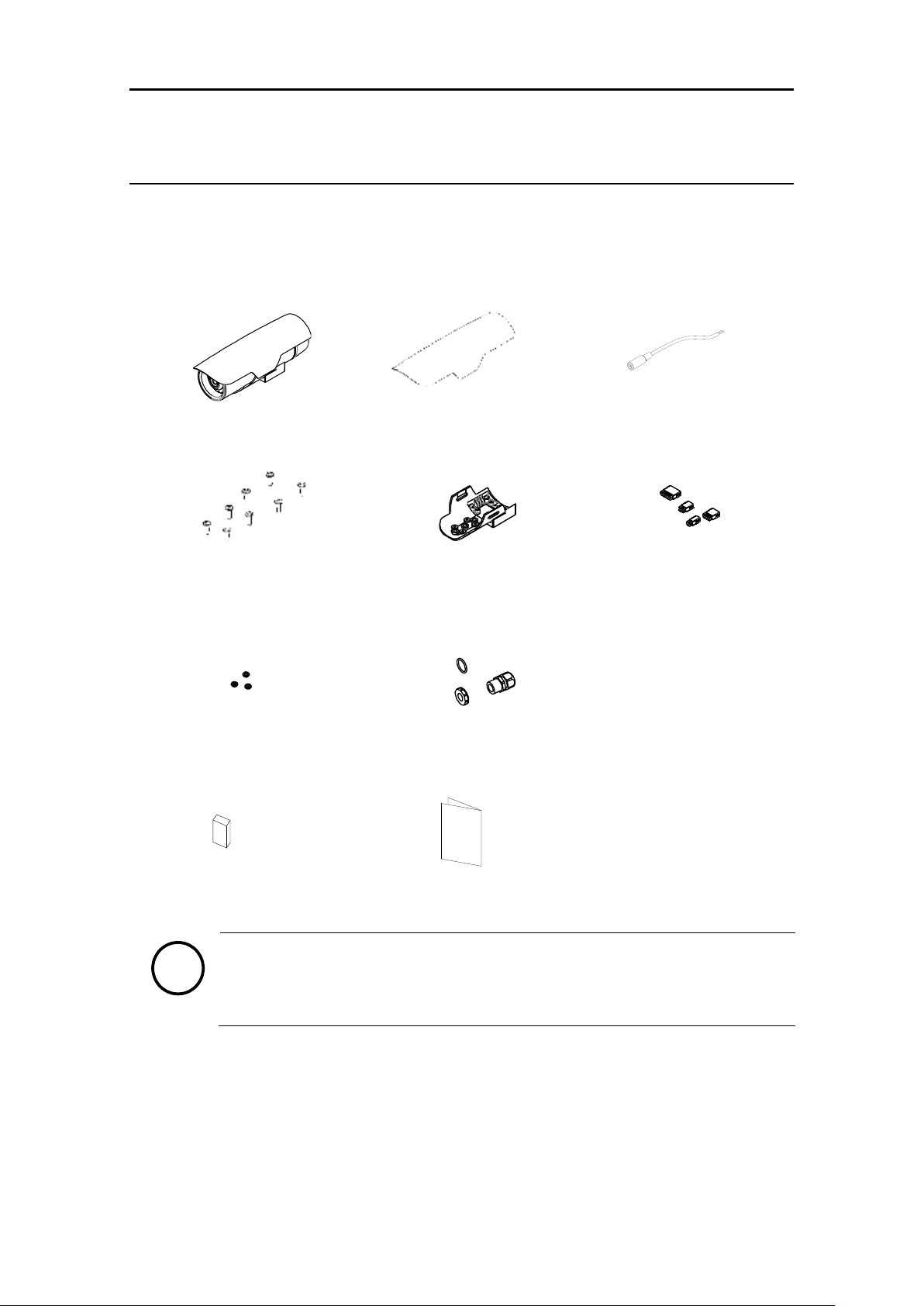
2. PACKAGE CONTENTS
Please unpack the package carefully and handle the equipment with care. The package contains:
The contents above are subject to change without prior notice.
Note
i
Camera
(
Below is the sunshield attached image)
Sunshield
DC Power Jack Cable
Tamper Resistant Screws x 8
Base Mount
Terminal Blocks
Stem Bumpers x 2 and 1
Spare
Cable Gland & Electrical Nut & O-ring
Silica Gel Packet
Quick Start Guide
Screw &
Plastic Anchor-3pcs
Quick Installation Guide
CABEL CORE
Screw &
Plastic Anchor-3pcs
Quick Installation Guide
Screw &
Plastic Anchor-3pcs
Quick Installation Guide
Screw &
Plastic Anchor-3pcs
Screw &
Plastic Anchor-3pcs
Screw &
Plastic Anchor-3pcs
ITC Series ITC6500 Series Installation Guide
CBC AMERICAS CORP. - EAST COAST +1 (919) 230-8700 | WEST COAST +1 (310) 222-8600 | MEXICO +52 (55) 5280-4660
ganzsecurity.com. 01/17
7
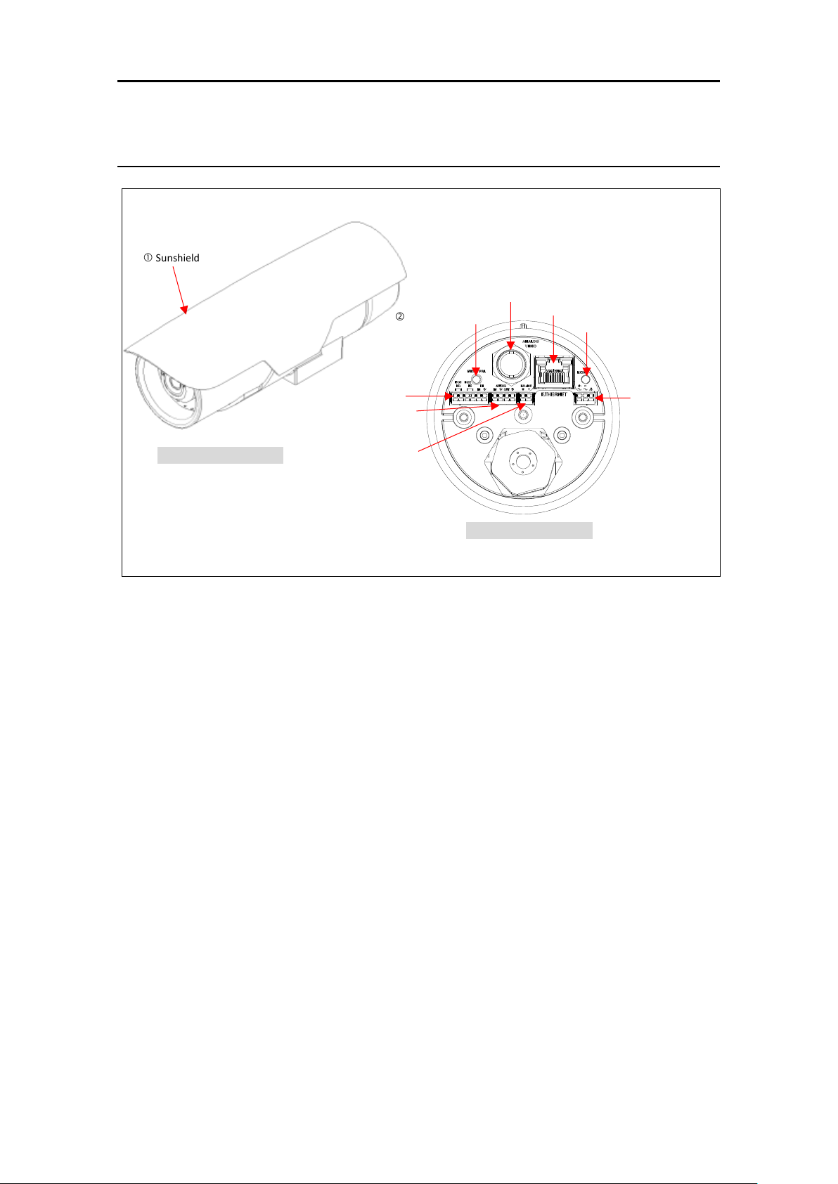
3. PART NAMES
① Sunshield
It prevents the lens from getting the direct sunlight.
② NTSC / PAL Button
The button switches the video output mode between NTSC and PAL.
Pressing the button will maintain the current video output mode unless pressing once more
to switch to the other mode.
③ Analogue Video Output
Connect a BNC output cable to see video via an analogue monitor.
④ RJ45 Socket
RJ45 LAN connector for 10/100 Base-T Ethernet (PoE supported).
⑤ Reset Button
Pressing this button reboots the camera or initializes the current settings of the camera to
the factory default settings. Refer to 6.3. Reboot and 6.4. Factory Default for the pressing
duration and more information.
⑥ Terminal Connectors for DI/DO
Connecting terminal blocks for digital input (sensor) and digital outputs (alarms)
Refer to 5. CONNECTIONS for more information.
⑦ Terminal Connectors for Audio In/Out
Connecting terminal blocks for audio input (microphone) and audio output (speaker)
Refer to 5.CONNECTIONS for more information.
⑧ Terminal Connector for RS-485
Connecting terminal blocks for RS-485
Refer to 5.CONNECTIONS for more information.
NTSC / PAL Button
Analogue Video Output
Sunshield
RJ45 Socket
[ Camera Profile Image ]
[ Back Panel of Camera ]
Reset Button
Terminal Connectors
for DI/DO
Terminal Connectors
for Audio In/Out
Terminal Connectors
for RS-485
* The model herein and its appearance are subject to change without any prior notice.
Terminal
Connectors
for power adaptor

ITC Series ITC6500 Series Installation Guide
CBC AMERICAS CORP. - EAST COAST +1 (919) 230-8700 | WEST COAST +1 (310) 222-8600 | MEXICO +52 (55) 5280-4660
ganzsecurity.com. 01/17
8
⑨ Terminal Connector for Power Adaptor
Connect terminal blocks for power supply
Refer to 5.CONNECTIONS for more information.
ITC Series ITC6500 Series Installation Guide
CBC AMERICAS CORP. - EAST COAST +1 (919) 230-8700 | WEST COAST +1 (310) 222-8600 | MEXICO +52 (55) 5280-4660
ganzsecurity.com. 01/17
9
4. INSTALLATION
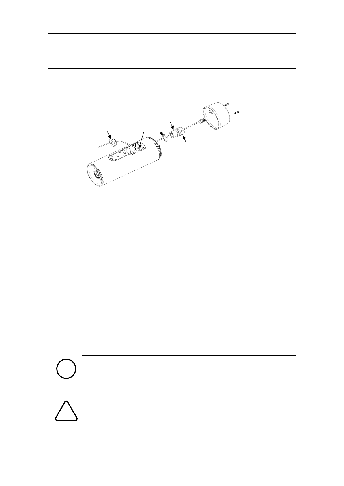
4.1. Installing Cable Gland
1) Detach the back cover by twisting it counter-clockwise.
2) Disassemble the provided cable gland unit. There will be an electrical nut, a rubber sealing
ring inserted inside the cable gland, a gland body, and a sealing nut.
3) Pass the electrical nut through the ends of the necessary cables.
4) Pass the cables through the holes both on the back and the bottom of the camera by referring
to the image above.
5) Pass the provided O-ring and gland body through the ends of the cables that are on the
backside of the camera.
6) Insert the cables into the rubber sealing ring at the point where about 4.5 inches (11.5 cm)
of the cable ends remains to connect to the corresponding connectors on the back panel later.
7) Push the rubber sealing ring through the claw of the gland body.
8) Insert the sealing nut into the thread of the gland body, and tighten it by turning the nut on
the thread. The rubber sealing ring will be tightened to fill the gap between the rubber sealing
ring and the cables.
9) Push the gland unit through the hole on the back of the camera so that the other end of the
thread on the gland unit will be inserted into the hole for gland near the bottom of the camera
body.
10) Fix the gland unit to the hole by inserting the electrical nut and tightening it on the thread
of the gland unit.
When you insert a video out cable together with other cables such as RJ45, DIDO,
and audio cables, a thin type of the BNC cable is recommended as the standard
BNC cable is too thick to be inserted together with the other cables into the rubber
sealing ring.
Use the detachable cable with a separate BNC connector to pass the hole of the
sealing nut. Otherwise, use the female type head of the BNC cable to pass the hole
of the sealing nut.
Note
i
Caution
!
Hole for gland
Electrical nut
O-ring
Gland body
Sealing nut
Loading...