


Ganz DR-16M55-RA-12TB, DR-16M55-RA-16TB, DR-16M55-RA-20TB, DR-16M55-RA-4TB, DR-16M55-RA-8TB User Manual
8CH/16CH
2U 5M HYBRID DVR
User Manual
ganzsecurity.com
Copyright
This manual without the manufacturer's approved copy and reprinted partially or in full, or translated into another language is prohibited.
Limitation of Liability
This product is designed to prevent fire and theft is not the main means. We shall not be liable for accidents or damage by using this product can result in liability for accidents or damage
In order to improve the performance of the product without prior notice to the product may be a firmware upgrade.
Content
OVERVIEW
4
4Safety Instruction
5Key Features
6What's included
7Rear Panel
9 Remote Control At a Glance
PLAY |
90 If you want to play |
90
INSTALLATION
10
MONITORING
22
10 Replacing HDD
15Basic Layout
16Connecting to an external device
24 Live Screen At a Glance
SYSTEM |
34 |
menu |
SETTING |
To move to the System Setup |
|
35 |
Camera Setting |
|
34 |
41 |
Display Setting |
49 |
Audio Setup |
|
|
50 |
User Setting |
|
52 |
Network Setup |
|
58 |
System Setting |
|
65 |
Storage |
|
69 |
Event Setup |
|
78 |
To start the Record Setup |
|
79 |
menu |
|
Record Setup |
ARCHIVING |
93 To start the Archive menu |
93
WEB VIEWER
96
MOBILE VIEWER
126
96 |
What is the Web Viewer? |
98 |
Live |
102 |
Search |
105 |
Setup |
126 |
nViewer |
ARCHIVE |
141 |
Backup Player |
VIEWER |
Getting started with the |
|
143 |
Backup Player At a Glance |
|
141 |
|
|
SEARCH
85
85To move to the Search menu while in monitoring
85To move to the Search menu while in playback mode
86Search Settings
APPENDIX
146
146Compatible HDD Specifications
147Troubleshooting (FAQ)

 Overview
Safety Instruction
This product was tested with a UPS to satisfy EN 61000-4-11 test conditions (voltage dips and short interruptions test) under the EN 50130-4: 2011 standard.
The Company shall not have any responsibility for any accident or damage that may incur during the use of the product. For your safety, we provide a few instructions about installation, manipulation, cleaning, assembly/disassembly of the product as below. So please read carefully and comply with the instructions.
Before installation
Comply with the following instructions to prevent a fire, explosion, system failure or electric shock.
~~ Remove the power supply module before proceeding.
~~ Check the input voltage (AC100V–AC240V) to the power supply module before connecting it. ~~ Keep the product away from humidity.
~~ Ensure that all devices connected to the product should be properly earth-grounded.
In operation mode
Comply with the following instructions to prevent a fire, explosion, system failure or electric shock.
~~ If you need to open the cover, consult with a service person who could help you do what you want to do.
~~ Do not connect multiple devices to a single power socket.
~~ Keep the product away from dust or too much combustible substances (ex: propane gas). ~~ Do not touch it with wet hand.
~~ Do not insert a conductor in the vent of the ventilation system. ~~ Do not apply excessive force to unplug the power cord.
Disassembly & Cleaning
~~ When cleaning on the surface, use a dry cloth.
~~ Do not wipe the product using water, paint thinner or organic solvents. ~~ Do never dismantle, repair or modify the product by your own.
During installation
To prevent an accident or physical injury and to operate DVR properly, please comply with the followings:
~~ Secure at least 18 centimeter of distance between cooling fan and wall for a proper ventilation. ~~ Install the product on a flat surface.
~~ Keep it away from direct sunlight or excessive temperature.
While in use
~~ Do not apply force to or shake it while using it.
~~ Do not move, throw away or put excessive force to it.
~~ Using any unrecommended HDD may cause a system failure. Check the compatibility list and use only compatible HDDs.
{A system failure or data loss caused by an incompatible HDD will void your warranty.}
4 | Overview

\\CAUTION
Replaceable batteries
Risk of Explosion if Battery is replaced by an Incorrect Type. Dispose of Used Batteries According to the Instructions.
Warning to service personnel
Double pole/neutral fusing
Ethernet Instruction
This equipment is indoor use and all the communication wiring are limited to inside of the building or similar word.
Key Features
This product is capable of receiving inputs from up to 16 channels of 5MP camera inputs of video and audio and recording onto a hard disk drive in real-time, as well as providing monitoring, playback and backup footages in excellent quality of 5MP resolution.
It also provides transferring video and audio data to the networked external devices, which allows remote monitoring environment for computers and mobile devices including cell phones.
~~ Up to 16 channels of 5MP camera video can be displayed at 480 fps in real time. ~~ Up to 16 channels of 5MP camera videos can be saved at maximum 160 fps.
~~ Simultaneous recording and playback of maximum 16 channels (at 480fps @ CIF) ~~ Supports H.264 HP (High Profile) CODEC
~~ Auto alarm feature with self-diagnostics on the system (HDD S.M.A.R.T, system temperature, network error, FAN error, etc.)
~~ Supports dual streaming for remote access service ~~ Supports HDD extension (eSATA)
~~ Various search methods (time, event, bookmark, thumbnail and text-in) ~~ Mass storage backup via USB port or FTP server
~~ Supports remote access and search using web browser
~~ Dedicated smart phone applications that can be used with iPhone and iPad or on Android OS ~~ 1080p Full HD GUI
Overview
English | 5

 Overview
What's included
|
|
|
|
|
|
|
|
|
|
|
|
|
|
|
|
|
|
|
|
|
|
|
|
|
|
|
|
|
|
|
|
|
|
|
Mouse x1 |
Remote Control x1 & Batteries (AAA x2) |
Power Cable x1 |
||||
DC 12V Adaptor x1 (90W) |
Adapter cable retainer clip x1 |
Screws (For fixing HDD / ODD) |
Terminal Block (7P/for 8CH) x2 |
Terminal Block (9P for 16CH) x2 |
Terminal Block 10P (for 16CH x4 / for 8CH x2) |
Quick Guide
6 | Overview
Rear Panel
\\8 channels
b |
c e |
d |
|
AUDIO IN |
|
|
|
|
|
1 |
3 |
5 |
7 |
|
|
|
|
|
|
|
AUDIO |
|
|
|
|
|
|
OUT |
|
SPOT |
2 |
4 |
6 |
8 |
|
|
OUT |
|
1 |
|
3 |
5 |
7 |
|
|
2 |
|
4 |
6 |
8 |
VGA |
|
|
|
VIDEO IN |
|
|
|
|
|
|
|
|
|
RELAY |
NO3 NO1 COM3 COM1 COM4 COM2 NC4 NC2 IN5 IN1 IN6 IN2 GND GND IN7 IN3 IN8 IN4 PANIC ARI ALARM IN |
RS-485 1 RS-485 2 |
D+ D+ D- D- GND GND RX TX AO3 AO1 AO4 AO2 GND GND RS-232 |
ALARM OUT |
WAN(UPLINK)
HD |
e-SATA USB LAN(DOWNLINK) |
DC12V |
MONITOR |
\\16 channels |
a |
f |
g hi j |
k |
|
|
|
|
|
|
b |
c |
e |
d |
1 |
3 |
5 |
AUDIO IN |
9 |
11 |
13 |
15 |
|
|
RELAY NO3 NO1 COM3COM1 COM4COM2 NC4 NC2 IN5 IN1 IN6 IN2 GND GND IN7 IN3 IN8 IN4 GND ARI |
RELAY NO7 NO5 COM7COM5 COM8COM6 NC8 NC6 IN13 IN9 IN14 IN10 GND GND IN15 IN11 IN16 IN12 GND PANIC |
RS-485 1 RS-485 2 |
D+ D+ D- D- GND GND RX TX AO5 AO1 AO6 AO2 GND GND AO7 AO3 AO8 AO4 RS-232 |
ALARMOUT |
7 |
|
|
|
|
|
|
|
|||||||
|
|
|
|
|
|
|
AUDIO |
|
|
|
|
|
|
|
|
|
|
|
|
|
|
OUT |
|
|
|
|
|
|
|
2 |
4 |
6 |
8 |
10 |
12 |
14 |
16 |
|
SPOT |
|
|
|
|
|
|
|
|
|
|
|
|
|
|
|
|
|
|
|
|
1 |
|
3 |
5 |
7 |
9 |
11 |
13 |
15 |
OUT |
WAN(UPLINK) |
|
|
|
|
2 |
4 |
6 |
8 |
10 |
12 |
14 |
16 |
VGA |
HD |
e-SATA USB LAN(DOWNLINK) |
DC12V |
|
|
|
VIDEO IN |
|
|
|
|
|
MONITOR |
|
a |
f g hi j |
k |
|
|
|
|
No. |
Name |
Description |
|
a |
VIDEO IN |
Video input terminal for cameras. |
|
b |
AUDIO IN |
Port for audio input. |
|
c |
AUDIO OUT |
Port for speaker connection. |
|
|
ALARM IN |
Alarm input signal port. |
|
|
ALARM OUT |
Alarm out signal port. O.C. (Pulled up to 5V via 10KOhm) |
|
d |
RELAY |
Relay Terminal output port. |
|
|
RS485 |
Ports for communication with external devices such as PTZ camera and system keyboard. |
|
|
RS232 |
Connection ports for signal cables to external devices such as PTZ camera, POS and ATM |
|
|
devices. |
|
|
|
|
|
|
e |
SPOT OUT |
Exclusive port for SPOT output only. (Connect to a TV monitor.) |
|
f |
VGA |
VGA monitor video output port. |
|
Overview
English | 7

 Overview
No. |
Name |
Description |
g |
HD-MONITOR |
HD monitor video output port. |
h |
e-SATA |
Connection port for external eSATA storage. |
i |
USB |
Used for connecting USB storage or mouse. |
|
WAN(UPLINK) |
Network port for connection to the Internet, router or hub. |
j |
LAN(DOWN LINK) |
Port for connecting the dedicated network device. |
|
Do not share it with other device. |
|
|
|
|
k |
DC12V |
Power input port. |
|
|
|
8 | Overview
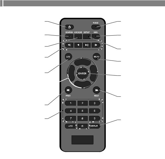
Remote Control At a Glance
POWER
Turn on or off the power.
SEARCH
Display the search window.
ARCHIVE
Display the backup window.
&, _, p, *
Used to change the direction or adjust the play speed in playback mode.
EXIT
$, %, _, + 
Use to move through the menus.
PREV
Channel
Function as channel selection button in live or playback mode. Or used for entering the password.
PANIC
Start the emergency recording.
SEQ
Switch to sequence mode.
SETUP
Display the system setup menu.
MENU
Display the tool bar on the live screen.
ENTER
Select a menu item or apply your settings.
NEXT
DISPALY
Switch the split mode.
Overview
English | 9
 Installation
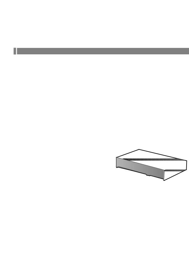
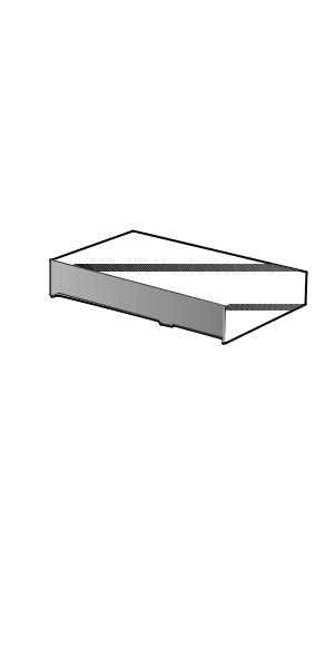
Replacing HDD
When an HDD is full or problematic, you can replace it with a new one by yourself.
\\8 / 16Ch Model
Below illustrations are based on the 8/16-channel model.
1.Remove 2 screws on both ends of DVR.
2.Pull the front side of the unit forward to separate it.
a |
b |
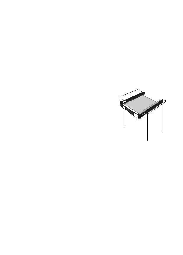
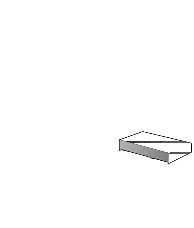
3. Hold the middle of HDD bracket's handle with index finger and pull it forward while sustaining the bracket handle with your thumb and middle finger as shown in the illustration.
10 | Installation
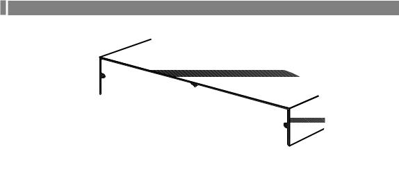
4. Once the HDD bracket is separated from the main unit, remove 4 screws on both ends of HDD bracket to separate the HDD from the bracket.
5. Install a new HDD and fasten 4 screws back to both ends of the bracket to fix it.
Whendirection.installing HDD, make sure to install in the correct
6.Push the bracket installed with new HDD back into the main unit until it is completely inserted.
7. Hold center of the ODD bracket’s holder by your index finger and pull it.
DVR Assembly
Direction
Installation
English | 11
 Installation
8. Install the ODD on the ODD bracket and fix it by fastening 4 screws on the bottom of it.
9. Insert the bracket with ODD into the main unit, push it until it’s fully inserted.
10. Assemble the front panel back to the unit.
JJWhen assembling the front panel to the main unit, make sure the marked part is tightly attached.
11.Fasten 2 screws on both ends of the main unit.
M3 |
X |
6 |
|
||
|
|
12 | Installation
\\If installed 5 HDD drives
Below illustrations are based on the 8/16-channel model.
1.Remove 2 screws on both ends of DVR.
2.Pull the front side of the unit forward to separate it.
Installation |
a |
b |
3. Hold the middle of HDD bracket's handle with index finger and pull it forward while sustaining the bracket handle with your thumb and middle finger as shown in the illustration.
English | 13
 Installation
4. Once the HDD bracket is separated from the main unit, remove 4 screws on both ends of HDD bracket to separate the HDD from the bracket.
5. Install a new HDD and fasten 4 screws back to both ends of the bracket to fix it.
Whendirection.installing HDD, make sure to install in the correct
6.Push the bracket installed with new HDD back into the main unit until it is completely inserted.
7. Assemble the front panel back to the unit.
JJWhen assembling the front panel to the main unit, make sure the marked part is tightly attached.
8.Fasten 2 screws on both ends of the main unit.
DVR Assembly
Direction
14 | Installation
Basic Layout
MIC |
3 |
5 |
AUDIO IN |
|
|
|
11 |
|
|
|
13 |
|
|
6 |
15 |
|
|
|
8 |
|
|
|
10 |
Camera |
|
|
|
Speaker |
|
|
Alarm |
|
|
|
VGA |
SPOT |
HD |
e-SATA |
Mouse IP Router |
Sensor |
Control |
Access |
ATM POS |
MONITOR |
Monitor |
MONITOR |
Storage |
or HUB |
|
Devices |
Controller |
|
JJSince the cable quality may affect directly to the video quality depending on the distance between the camera and DVR, it is recommended to consult an authorized installer when installing the DVR.
Installation
English | 15

 Installation
Connecting to an external device
\\Connecting to the monitor
This product supports 1080p 60 Hz HDMI monitors and regular monitors that support DVI and VGA inputs. Use the switch on the product’s rear side to set it for HDMI or VGA monitor. Connect an HDMI cable to the port on the product’ s rear bottom, or connect an HDMI-DVI converter cable to connect a DVI monitor. Or, use VGA cable to connect the product with a VGA monitor.
~~ Once the product is set for NTSC or PAL output, connect cameras of the corresponding video standard for proper operations.
JJMake sure to connect the product to a monitor that supports 1920x1080 at 60Hz. (HDMI, DVI, VGA)
\\Power Connection
Connect the power cable supplied with the product into the power socket on the main unit’s rear side.
1 |
3 |
5 |
AUDIO IN |
9 |
11 |
13 |
15 |
|
RELAY NO3 NO1 COM3COM1 COM4COM2 NC4 NC2 IN5 IN1 IN6 IN2 GND GND IN7 IN3 IN8 IN4 GND ARI |
RELAY NO7 NO5 COM7COM5 COM8COM6 NC8 NC6 IN13 IN9 IN14 IN10 GND GND IN15 IN11 IN16 IN12 GND PANIC |
RS-485 1 RS-485 2 |
D+ D+ D- D- GND GND RX TX AO5 AO1 AO6 AO2 GND GND AO7 AO3 AO8 AO4 RS-232 |
ALARMOUT |
7 |
|
|
|
|
|
|
|||||||
|
|
|
|
|
|
|
AUDIO |
|
|
|
|
|
|
|
|
|
|
|
|
|
OUT |
|
|
|
|
|
|
2 |
4 |
6 |
8 |
10 |
12 |
14 |
16 |
SPOT |
|
|
|
|
|
|
|
|
|
|
|
|
|
WAN(UPLINK) |
|
|
|
||
1 |
|
3 |
5 |
7 |
9 |
11 |
13 |
OUT |
|
|
|
||
|
15 |
|
|
|
|
|
|||||||
2 |
4 |
6 |
8 |
10 |
12 |
14 |
16 |
VGA |
HD |
e-SATA USB LAN(DOWNLINK) |
|
|
|
VIDEO IN |
|
|
|
|
|
MONITOR |
Power adaptor 
JJFor stable operation of the product, it is recommended to use the |
. (12V, 10A) |
JJMake connection when the power is not applied yet.
JJArrange up the cables and be careful not to peel off the cable coating.
JJDo not place the power cord under the carpet or rug. The power cord is usually earth-grounded. However, even if it's not earth-grounded, do never modify it on your own for earth-grounding.
JJDo not insert multiple devices in a single power socket. Otherwise, it may cause a power overload.
JJFor stable power supply, this product provides two separate adaptors and two corresponding AC cords by factory default. Make sure all cables are connected properly.
16 | Installation

\\Alarm I/O Connection |
|
|
|
|
|
|
|
|
|
|
|
|
|
|
|
||||
|
|
|
|
|
|
|
|
|
COM1 |
|
|
IN |
|
1 |
485- 2 |
D+ -D |
|
|
|
|
|
|
AUDIO IN |
|
|
|
|
RELAY |
COM2 NC2 IN1 IN2 GND IN3 IN4 |
|
-2 GND TX AO1 AO2 GND AO3 AO4 |
ALARMOUT |
|||||||
|
|
|
|
|
|
|
NO3RELAYNO1 NO3 COM3 COM4 NC4 IN5IN1IN5 IN6 GND IN7 IN8 GND |
GNDARI YREL NO7 COM7 COM6COM8 NC6NC8 IN9IN13 IN10IN14 GNDGND IN11IN15 IN12IN16 PANICGND |
485-RS 485-RS D+ -D GND RX AO5 AO6AO2AO6 GNDGND AO7 AO8 AO8232-RS OUTALARMRS232- |
||||||||||
|
|
|
|
|
|
|
|
|
COM3NO1 COM4 NC4NC2 |
IN6 GND IN7IN4 IN8 |
ALARM |
COM5 |
485RS- RS |
D+ D GND- RX AO5 |
AO7 |
|
|||
|
|
|
|
|
|
|
|
|
COM1 COM2 |
IN2 GND 3I |
ARI |
NO5 |
|
|
1 _ D+ |
GND TX AO1 |
AO3 AO4 |
|
|
1 |
3 |
5 |
7 |
9 |
11 |
13 |
15 |
|
|
|
|
|
|
|
|
|
|
|
|
|
|
|
|
|
|
|
AUDIO |
|
|
|
|
|
|
|
|
|
|
|
|
|
|
|
|
|
|
|
OUT |
|
|
|
|
|
|
|
|
|
|
|
|
2 |
4 |
6 |
8 |
10 |
12 |
14 |
16 |
SPOT |
|
|
|
|
|
|
|
|
|
|
|
|
|
|
|
|
|
|
|
|
WAN(UPLINK) |
|
|
|
|
|
|
|
|||
1 |
|
3 |
5 |
7 |
9 |
11 |
13 |
OUT |
|
|
|
|
|
|
|
|
|||
|
15 |
|
|
|
|
|
|
|
|
|
|
|
|||||||
2 |
4 |
6 |
8 |
10 |
12 |
14 |
16 |
VGA |
HD |
e-SATA USB LAN(DOWNLINK) |
DC12V |
|
|
|
VIDEO IN |
|
|
|
|
||||
|
|
|
|
|
|
|
|
MONITOR |
To connect the alarm input signal
Connect the signal line of an alarm input device such as sensor to the rear [ALARM IN] port.
Loosen the screws on both the alarm input port and [GND] port of the provided terminal block plug.
Insert one end of alarm signal cable through the [AO1] or [AO8] terminal hole below the screw hole, and then fasten the screw.
Insert the ground signal wire into the hole of the [GND] port (shown also below the screw), and tighten the screw.
To check proper insertion of cable, stop pushing and gently pull the cable and test whether it disconnects. To disconnect a cable, push the bottom side of the terminal and pull out the cable.
To connect the alarm output signal
Connect the signal line of an alarm output device to the rear [RELAY] port.
Loosen the screws on the [NO] and [NC] ports and the [COM] port of the provided terminal block plug.
Insert the alarm signal wire into the hole of the [NO] or [NC] input port (shown below the screw), and tighten the screw.
Check the relay output type of Normal Open or Normal Close before selecting a proper type (NO or NC).
iNO(Normal Open) : Normally Open but switching to Close if an alarm out occurs.
iCOM : Insert the grounding wire.
iNC(Normal Close) : Normally Close but switching to Open if an alarm out occurs.
3.Insert the ground signal wire into the hole of the [COM] port (shown also below the screw), and tighten the screw. Or, you can connect the signal cable of the alarm output device to the [ALARM OUT] port on the rear side.
1.Loosen the screws on the [AO1] and [AO8] ports and the [GND] port of the provided terminal block plug.
2. Insertscrew.the alarm signal wire into the hole of the [AO1] or [AO8] input port (shown below the screw), and tighten the Check the relay output type of Normal Open or Normal Close before selecting a proper type (NO or NC).
Insert the ground signal wire into the hole of the [GND] port (shown also below the screw), and tighten the screw.
To check proper insertion of cable, stop pushing and gently pull the cable and test whether it disconnects. To disconnect a cable, push the bottom side of the terminal and pull out the cable.
Install the wire-connected terminal block in the rear port.
Installation
English | 17

 Installation
\\Communication Port
|
|
|
|
|
|
|
|
|
|
|
1 |
485- 2 |
|
2 |
GND TX AO1 AO2 GND AO3 AO4 |
ALARMOUT |
|
|
|
|
|
|
|
|
|
|
|
|
|
|
D+ -D |
|
|
||
|
|
|
AUDIO IN |
|
|
|
|
COM1 |
|
COM5 |
485-RS RS D+ D AO1AO5RXGNDGND- |
AO3 AO4AO7 |
|||||
|
|
|
|
|
|
|
RELAY NO3NO1 COM3 COM4COM2 NC4NC2 IN5IN1 IN6IN2 GNDGND IN7IN3 IN8IN4 GNDARI |
RELAY NO7NO5 COM7 COM8COM6 NC8NC6 IN13IN9 IN14IN10 GNDGND IN15IN11 IN16IN12 GNDPANIC |
485-RS 485-RS D+ -D GND RX AO5 AO6AO6AO2 GNDGND AO7 AO8 AO8232-RS ALARMOUT232RS- |
||||||||
|
|
|
|
|
|
|
|
|
|
|
|
1 |
D+_- |
TX |
|
|
|
1 |
3 |
5 |
7 |
9 |
11 |
13 |
15 |
|
|
|
|
|
|
|
|
|
|
|
|
|
|
|
|
|
AUDIO |
|
|
|
|
|
|
|
|
|
|
|
|
|
|
|
|
|
OUT |
|
|
|
|
|
|
|
|
|
|
2 |
4 |
6 |
8 |
10 |
12 |
14 |
16 |
SPOT |
|
|
|
|
|
|
|
|
|
|
|
|
|
|
|
|
|
WAN(UPLINK) |
|
|
|
|
|
|
|
||
1 |
3 |
5 |
|
7 |
9 |
11 |
13 |
OUT |
|
|
|
|
|
|
|
||
|
15 |
|
|
|
|
|
|
|
|
|
|||||||
2 |
4 |
6 |
8 |
10 |
12 |
14 |
16 |
VGA |
HD |
e-SATA USB LAN(DOWNLINK) |
DC12V |
|
|
|
VIDEO IN |
|
|
|
|
|
MONITOR |
RS-485 Connection
Connect a PTZ Camera or Keyboard Controller.
After connecting the control device, be sure to match the connection settings between DVR and device. Make communication settings in <Control Device>. (page 62)
Use a signal cable to connect the [D+] port of the terminal block plug and the [D+] port of the keyboard controller. Connect the [D+] port of the terminal block plug and the [D+] port of the keyboard controller.
Connect the [GND] port of the terminal block plug and the [GND] port of the keyboard controller.
For RS-485 communication configuration, refer to the user’s manual of the applicable PTZ camera or keyboard controller.
RS-232 Connection
You can connect PTZ cameras, POS or ATM devices.
For connection of the text-in device, refer to the user manual of the text-in device.
\\Audio Device Connection
You can connect an audio output device such as speaker amplifier.
Connect the audio input device such as microphone to the rear Audio In port, connect the audio output device such as speaker amplifier to the Audio Out port.
18 | Installation

\\Storage and Mouse Connection
1 |
3 |
5 |
AUDIO IN |
9 |
11 |
13 |
RELAY |
NO3 NO1 COM3COM1 COM4COM2 NC4 NC2 IN5 IN1 IN6 IN2 GND GND IN7 IN3 IN8 IN4 GND ARI |
RELAY |
NO7 NO5 COM7COM5 COM8COM6 NC8 NC6 IN13 IN9 IN14 IN10 GND GND IN15 IN11 IN16 IN12 GND PANIC |
RS-485 1 RS-485 2 |
D+ D+ D- D- GND GND RX TX AO5 AO1 AO6 AO2 GND GND AO7 AO3 AO8 AO4 RS-232 |
ALARMOUT |
7 |
15 |
|
|
|
|
|
|
AUDIO
OUT
2 |
4 |
6 |
8 |
10 |
12 |
14 |
16 |
|
SPOT |
|
|
|
|
|
|
|
|
|
|
|
|
1 |
3 |
|
5 |
7 |
9 |
11 |
13 |
15 |
OUT |
WAN(UPLINK) |
2 |
4 |
|
6 |
8 |
10 |
|
|
|
|
|
|
|
|
|
VIDEO IN |
|
|
|
|
|
|
Installation
External HDD |
USB HDD |
USB storage USB Mouse |
(for video recording) |
(for backup only) |
(backup, |
|
|
firmware |
|
|
updating) |
eSATA Storage
If the internal storage space is insufficient, you can extend your storage capacity by adding an eSATA storage device to the rear eSATA port.
JJUsing devices other than recommended eSATA products may cause serious problem.
USB Device
You can connect and use USB storage devices for backup of recorded video, saving snapshots, firmware updating, importing/exporting user configurations. Also, USB mouse can be connected for DVR manipulations.
JJIf you need to connect a USB HDD with a high power consumption, it is recommended to use a separate power source for that HDD.
English | 19

 Installation
\\Network Connection
PC connection in the local network
You can connect DVR to a PC in the same network and control or manipulate it on the PC monitor.
Camera
1
 2
2
3 |
AUDIO |
|
5 |
IN |
|
|
7 |
|
|
|
9 |
|
|
11 |
4 |
|
13 |
6 |
8 |
15 |
|
10 |
|
|
|
|
|
|
12 |
|
|
14 |
|
|
16 |
|
|
11 |
|
|
13 |
15
VIDEO IN |
14 |
16 |
SPOT |
|
|
OUT |
|
|
|
|
WAN(UPLINK) |
VGA |
|
|
HD |
e- |
|
MONITOR |
|
|
|
SATA USB |
LAN(DOWNLINK) |
|
|
DC12V
 Broadband
router or hub
Local PC


 Local PC
1. Connect the [ETHERNET] port in the rear panel to the router or hub. 2. Connect the local PC to the router or hub.
AUDIO IN
1 |
3 |
5 |
7 |
9 |
11 |
13 |
15 |
|
|
|
|
|
|
|
AUDIO |
|
|
|
|
|
|
|
|
|
|
|
|
|
OUT |
|
|
|
|
|
|
2 |
4 |
6 |
8 |
10 |
12 |
14 |
16 |
|
SPOT |
|
|
WAN(UPLINK) |
|
|
|
|
|
|
|
|
|
|
|
|
|
||
1 |
3 |
|
5 |
7 |
9 |
11 |
13 |
15 |
OUT |
|
|
WAN(UPLINK) |
|
2 |
4 |
|
6 |
8 |
10 |
12 |
14 |
16 |
VGA |
HD |
e-SATA |
USB |
DC12V |
|
|
|
|
VIDEO IN |
|
|
|
|
|||||
|
|
|
|
|
|
|
|
|
MONITOR |
|
|
||
|
|
|
|
|
|
|
|
|
|
|
|
LAN(DOWNLINK) |
|
PWR |
RESET |
4 |
3 |
1 |
Broadband router or hub
Local PC |
Local PC |
3. Enter the address in the Web browser of your PC in the format of: “http://IP address:Web service port”
(Ex : http://192.168.0.23:8080) The web service port is set to 8080 by default. From the Network Setup screen, you can change the port number.
If using the dedicated PC S/W, refer to the user manual of the program.
4.Provide the ID and password before logging in. Then, you can view the monitoring screen.
The initial administrator ID is “ADMIN” and the password should be set when logging in for the first time.
JJFor security purpose, change the password before you use the product for the first time after purchasing it.
20 | Installation
PC connection from a remote network
You can connect DVR to a PC or mobile device in the same remote network and control or manipulate it on the monitor of the PC or mobile device.
1 |
|
|
3 |
AUDIO |
|
5 |
IN |
|
|
7 |
|
|
|
9 |
2 |
|
11 |
|
13 |
|
4 |
|
15 |
6 |
8 |
|
|
10 |
|
|
|
|
|
|
12 |
|
|
14 |
|
|
16 |
|
|
11 |
|
|
13 |
15 |
SPOT |
|
VIDEO IN |
OUT |
|
WAN(UPLINK) |
||
16 |
||
14 |
|
Internet |
VGA |
|
DC12V |
HD |
e-SATA |
||
|
MONITOR |
|
|
|
|
USB |
|
|
|
LAN(DOWNLINK) |
|
|
ADSL modem |
|
|
Remote PC |
|
Broadband |
Internet |
Smart Phone |
|
router |
Direct |
|
Local PC |
|
Connection |
|
|
|
|
|
Local PC |
|
|
1. Connect the [ETHERNET] port in the rear panel to the router.
1 |
3 |
5 |
AUDIO IN |
9 |
11 |
13 |
15 |
|
|
|
|
IN5 IN1 IN6 IN2 GND GND IN7 IN3 IN8 IN4 |
IN13 IN9 IN14 IN10 GND GND IN15 IN11 IN16 IN12 |
RS-485 1 |
D+ D- GND GND |
AO5 AO1 AO6 AO2 GND GND AO7 AO3 AO8 AO4 |
|
|
7 |
|
|
|
|
|
|
|
|
|
|
|
|||||||
|
|
|
|
|
|
|
AUDIO |
|
|
|
|
|
|
|
|
|
|
|
|
|
|
|
|
|
|
OUT |
|
|
|
|
|
|
|
|
|
|
|
2 |
4 |
6 |
8 |
10 |
12 |
14 |
16 |
|
SPOT |
|
|
|
WAN(UPLINK) |
|
|
|
|
|
|
|
|
|
|
|
|
|
|
|
|
|
|
|
|
|
|
||
1 |
|
3 |
5 |
7 |
9 |
11 |
13 |
15 |
OUT |
|
|
|
WAN(UPLINK) |
|
|
|
|
|
2 |
|
4 |
6 |
8 |
10 |
12 |
14 |
16 |
VGA |
HD |
e-SATA |
USB |
|
|
|
DC12V |
|
|
|
|
|
|
VIDEO IN |
|
|
|
|
|
|
|
|
||||||
|
|
|
|
|
|
|
|
|
MONITOR |
|
|
|
|
|
|
|||
|
|
|
|
|
|
|
|
|
|
PWR |
RESET |
4 |
3 |
|
|
1 |
Broadband router |
|
ADSL modem |
Local PC |
2. Connect the [ETHERNET] port of the router directly to the fixed IP LAN cable, or connect it to the ADSL modem.
3. If using the router, set the port forwarding and enter the DDNS address in the address bar (web browser) of the remote PC, or of the dedicated software program or mobile phone.
For the IP and DDNS address settings, refer to “Network Setup”. (page 52)
4. If the MAC address of the DVR is 00-11-5F-12-34-56 and the web port number is 8080, enter "http://00115f123456. dvrlink.net:8080" in the address bar of the web browser.
If you have renamed DDNS as “mydvr”, you can make network connection at http://mydvr.dvrlink.net:8080.
Installation
English | 21

 Monitoring
\\START
1. Connect the adaptor to the power input port on the DVR’s rear side.
JJMake connection when the power is not applied yet.
2.Turn on the power switch in the rear panel of DVR. With a beep, the logo screen appears several seconds after the front LED turns on.
3.When the booting process is completed, the live screen then the login screen appears.
\\User Information Setup
SET PASSWORD
For enhanced security of DVR, enter a new password on DVR boot. Enter a new password in the <NEW PASSWORD> field.
Enter exactly the same password in the <CONFIRM NEW PASSWORD> field.
Click <OK>. The password changes to the set password.
AUTHENTICATION INFORMATION SETUP
In case you forgot your PASSWORD, you can reset it through email verification.
Enter your E-MAIL in <E-MAIL ADDRESS> for verification.
Click <OK>. E-MAIL ADDRESS is registered.
JJIn case you forgot your password, you can click <Forgot Password?> to verify your E-MAIL and change your password.
\\Log In
To manipulate or access the menus of DVR, you should have logged in. When the system starts, the login screen appears.
Select a user and provide the password.
The initial administrator ID is “ADMIN” and the password should be set when logging in for the first time.
Click <OK>.
If the login information is correct and valid, you will see the live screen.
JJFor security purpose, change the password before you use the product for the first time after purchasing it.
22 | Monitoring

Forgot Password?
In case you forgot your password, you can click <Forgot Password?> to verify your E-MAIL and change your password. Click <Forgot Password?>.
Enter the email address you registered on the initial DVR boot, and then click <APPLY>.
3. Click <SEND VERIFICATION CODE> to proceed with the email verification.
4. Reset the password.
\\Log Out
To prevent unauthorized access, it is recommended to log out when you leave the screen.
Hover the cursor near the bottom of the screen to display the menu.
1.In the monitoring screen, click <MENU> in the bottom left corner of the screen to <LOG OUT>, or press the [LOGOUT] button on the remote control.
2.While logged out, Search / Backup / System Settings / Record Settings / Exit menus are restricted to use.
\\System Shutdown
1. In the monitoring screen, click <MENU> in the bottom left corner of the screen to <SHUTDOWN> the system, or press the [POWER] button on the remote control.
Use the virtual keyboard to enter the password.
Be sure to turn off the power switch in the rear panel.
JJIf you turn off the system in an abnormal manner such as removing the power cord while the system is in operation, the disk will have or increase the bad sectors, causing data loss and shortened life cycle of the disk.
Monitoring
English | 23

 Monitoring
Live Screen At a Glance
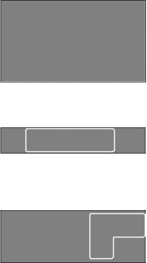
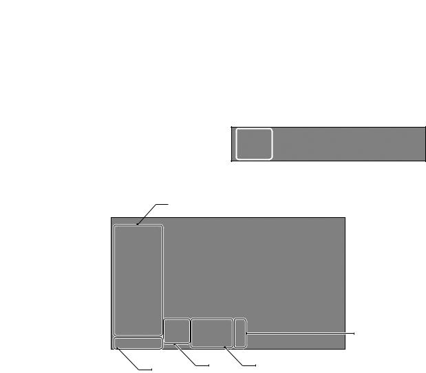
The live screen largely consists of three components: video window, status bar and timeline zone.
Video Window Quick Menu

 Timeline
|
Status Bar |
|
\\Video Window |
|
|
Icons used in the video window. |
|
|
Item |
Description |
|
Camera ID |
Show the camera ID. |
|
|
Displayed if an event recording is reserved. |
|
Record Mode |
Display the status of the continuous recording. |
|
Display the recording status when an alarm occurs. |
||
Icons |
||
Display the recording status when a motion event occurs. |
||
|
||
|
Display the status of the emergency recording. |
|
Audio I/O Icons |
The audio signal of the connected camera is outputting. |
|
Motion Detection |
A motion is detected by the connected camera. |
|
Icon |
||
|
24 | Monitoring
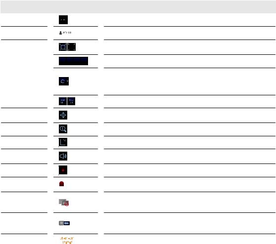
\\Status Bar
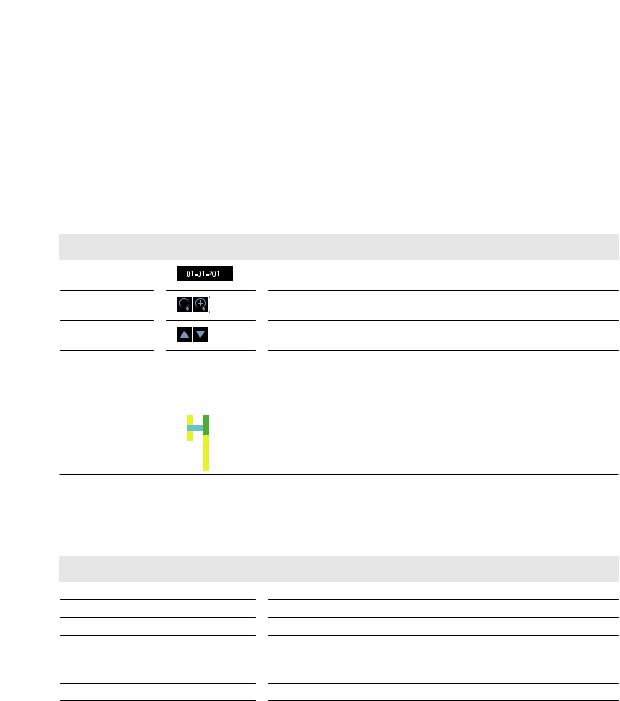
Press the [▼] button on the remote control, or place the mouse in the lower area of the screen to display the status bar.
Item |
|
|
|
|
|
|
|
|
|
|
|
Description |
|
Menu Button |
|
|
|
|
|
|
|
|
|
|
|
Select one of the system setup, search and backup menu items before accessing it. |
|
|
|
|
|
|
|
|
|
|
|
|
|||
User ID |
|
|
|
|
|
|
|
|
|
|
|
Show the ID of the user who has currently logged in. |
|
|
|
|
|
|
|
|
|
|
|
|
|||
|
|
|
|
|
|
|
|
|
|
|
|||
|
|
|
|
|
|
|
|
|
|
|
|
|
Edit the screen layout to show the status bar and timeline at all times or only when |
|
|
|
|
|
|
|
|
|
|
|
|
|
|
|
|
|
|
|
|
|
|
|
|
|
|
|
the mouse cursor hovers on the status bar/timeline. |
|
|
|
|
|
|
|
|
|
|
|
|
|
|
Screen Control |
|
|
|
|
|
|
|
|
|
|
|
Select a split mode. |
|
|
|
|
|
|
|
|
|
|
|
|
|||
|
|
|
|
|
|
|
|
|
|
|
|||
|
|
|
|
|
|
|
|
|
|
|
Select Auto Sequence Mode. |
||
|
|
|
|
|
|
|
|
|
|
|
|||
Buttons |
|
|
|
|
|
|
|
|
|
|
|
When a user arranges channels on desired tiles of split screen, such setting is listed |
|
|
|
|
|
|
|
|
|
|
|
|
|
|
for later access. Selecting a screen setup directly switches the screen mode as |
|
|
|
|
|
|
|
|
|
|
|
|
|
configured. |
|
|
|
|
|
|
|
|
|
|
|
|
|
Display or hide the OSD menu on the screen. |
|
|
|
|
|
|
|
|
|
|
|
|
|
|
PTZ |
|
|
|
|
|
|
|
|
|
|
|
Move to the PTZ screen. You can control the PTZ operations of a PTZ-compliant |
|
|
|
|
|
|
|
|
|
|
|
|
|||
|
|
|
|
|
|
|
|
|
|
|
|||
|
|
|
|
|
|
|
|
|
|
|
camera on the PTZ screen. |
||
|
|
|
|
|
|
|
|
|
|
|
|
|
|
Zoom |
|
|
|
|
|
|
|
|
|
|
|
Move to the Digital Zoom. |
|
Quick Log |
|
|
|
|
|
|
|
|
|
|
|
|
Display the log list of the recent recording events. |
|
|
|
|
|
|
|
|
|
|
|
|
||
|
|
|
|
|
|
|
|
|
|
|
|
||
|
|
|
|
|
|
|
|
|
|
|
|
||
Audio Channel |
|
|
|
|
|
|
|
|
|
|
|
You can use the camera supporting the audio input to listen to the audio. |
|
|
|
|
|
|
|
|
|
|
|
|
|||
Selection Button |
|
|
|
|
|
|
|
|
|
|
|
||
|
|
|
|
|
|
|
|
|
|
|
|
||
Panic Record |
|
|
|
|
|
|
|
|
|
|
|
|
Start the panic recording. |
Alarm Indicator |
|
|
|
|
|
|
|
|
|
|
|
Turns on if an event occurs. It does not turn on if no reaction to the event is yet defined. |
|
|
|
|
|
|
|
|
|
|
|
|
Click this to check the information of the event that occurred. |
||
|
|
|
|
|
|
|
|
|
|
|
|||
Network |
|
|
|
|
|
|
|
|
|
|
|
Check if network connection is made via an external PC or mobile device. Click this |
|
Connection Status |
|
|
|
|
|
|
|
|
|
|
|
to view the details of the concurrent users and to check the network connection |
|
|
|
|
|
|
|
|
|
|
|
|
status. For more information, refer to "Network Setup". (page 52) |
||
|
|
|
|
|
|
|
|
|
|
|
|||
Disk Space |
|
|
|
|
|
|
|
|
|
|
|
Show the disk space information. If you have set the disk overwrite mode, it will be |
|
|
|
|
|
|
|
|
|
|
|
|
displayed "OW" (Over Write) from the start point of the overwriting. Click this to view |
||
Date & Time |
|
|
|
|
|
|
|
|
|
|
|
the details of the disk status. For more information, refer to "Record Setup". (page 79) |
|
5 |
|
|
|
|
|
Display the current time and date. |
|||||||
|
|
|
|
|
|
|
|
||||||
|
|
|
|
|
|
|
|
|
|
|
|
|
|
Monitoring
English | 25
 Monitoring
\\Timeline
Press the [ ] button on the remote control or move the cursor to the right of the screen to display the timeline. Double-click the timeline to move to the video screen. Drag and drop it to make backup or event search for the specified area.
Item |
|
|
|
|
|
|
Description |
||
Timeline Date |
|
|
|
|
|
|
Display the date of the current timeline. |
||
5 |
|||||||||
|
|
|
|
|
|
Click this to select a desired date of the timeline. |
|||
Expand/Collapse |
|
|
|
|
|
|
|
||
|
|
|
|
|
|
|
Expand or collapse the timeline. |
||
the timeline |
|
|
|
|
|
|
|
||
|
|
|
|
|
|
|
|||
Navigation through |
|
|
|
|
|
|
|
Navigate through the timeline. |
|
|
|
|
|
|
|
|
|
||
Timeline |
|
|
|
|
|
|
|
You can also use the mouse wheel to do the navigation. |
|
|
|
|
|
|
|
|
|
||
|
|
|
|
|
|
|
|
|
Display the recording data with time. The color of each bar indicates the following: |
|
|
|
|
|
|
|
|
|
|
|
|
|
|
|
|
|
|
|
|
Timeline Bar |
|
|
|
|
|
|
~~ Green : Continuous Recording |
||
|
|
|
|
|
|
||||
|
|
|
|
|
|
||||
|
|
|
|
|
|
~~ Red : Alarm Recording |
|||
|
|
|
|
|
|
||||
|
|
|
|
|
|
||||
~~ Blue : Motion Recording
~~ Yellow: Panic Recording
\\Quick Menu
Right click on a channel to display a quick menu popup window.
Item |
Description |
Channel No |
Display the number of the current channel. |
PLAYBACK |
Start playing the video of the selected channel from the specified time. |
ZOOM |
Operates (digital) zooming on the selected channel. |
SNAPSHOT |
Capture the current live video and save it in the .jpeg format. |
Then, you can save the captured video in the HDD or export it to an external |
|
|
USB memory device. |
CAM CHANGE |
You can assign the selected screen to another channel. |
CALIBRATION |
You can calibrates the camera image. |
26 | Monitoring
\\Using the status bar in the live mode
Changing Channel
You can change channel in LIVE/PLAYBACK screen. Right-click your mouse at the selected channel, and then click the [CAMCHANGE] to select your desired [CAMXX]. Or you can drag & drop your desired channel into the screen to assign.(ex: Changing the channels of CAM1 and CAM2)
\\Using the status bar in the live mode
Selecting a split mode
Click a desired split mode from 1, 4, 9 and 16 split screen. Or press the [DISPLAY] button on the remote control until a desired split mode is displayed.
Allocating Live Screen Channel
Move a channel to your desired location by dragging & dropping with your mouse. This enables you to modify the allocation of your views depending on your taste.However, you cannot change the recording channel. These settings are not saved and initialized when restarting your system.
Auto sequence
Click the Sequence button in the status bar, or press the [SEQ] button on the remote control to perform the specified sequence mode.
You can configure the sequence settings in <SEQUENCE>.
For details, refer to “Sequence”. (page 43)
Monitoring
English | 27
 Monitoring
Controlling PTZ
You can control PTZ cameras connected to each channel.Use the mouse to click PTZ button on the status bar, or press the [PTZ] button of the remote control to initiate the predefined sequence.
In PTZ mode, use buttons on the screen to control
PTZ or use [ZOOM], [FOCUS] and [PRESET] buttons of the remote control.
 Select Preset
Record/Screen Control/
Zoom
SCAN/TOUR |
Move |
Zoom/Focus/Iris Adjustment |
Settings |
|
|
28 | Monitoring

Pan/Tilt Control
Use mouse to rotate the PTZ camera in the direction of up/down/left/right and diagonal directions.
You can control Pan/Tilt with [▲▼ ] buttons of the remote control.
Zoom / Focus Control
You can control the PTZ camera for zooming and focus adjustment.
Click <ONE PUSH FOCUS> button to adjust the camera’s focus automatically.
If the connected camera supports manual iris adjustment, you can adjust the iris setting.
You can control by using [ZOOM] and [FOCUS] buttons of the remote control.
1. Click <PROPERTY> and change to a desired setting of the PTZ camera (for auto focus, auto IRIS, pan/tilt speed, zoom speed, focusing speed, iris speed).
Depending on the PTZ camera manufacturer and model, some of the PTZ properties may not be applicable.
iCH : Selects the PTZ camera connected to the DVR.
iPRESET (No. / Name) : You can select the preset number and name.
Up to 255 presets can be selected for a PTZ camera, while up to 16 presets can be registered to one DVR.
Monitoring
English | 29

 Monitoring
2. Control the Camera’s PTZ while watching the video. Press the <SET> button to append the preset.
i : Click the shortcut icon to move to the corresponding PTZ (preset) position.
i : Click Delete icon to delete the corresponding preset.
PRESET: Memorizes the PTZ camera’s framing for direct access at a later time.
SCAN/TOUR
1. Select <SCAN> and click the <ON> button. 2. Click the < > icon.
3. Select a user-defined preset and register it.
iDWELL : Sets the dwell time of 00 seconds before moving to the next preset location.
<SCAN> function patrols two preset positions at the specified speed and interval for back-and-forth monitoring.
4.Select <TOUR> and click the <ON> button.
5.Click the < > icon.
6.Select a user-defined preset and register it.
iDWELL : Sets the dwell time of 00 seconds before moving to the next preset location.
<TOUR> function patrols multiple presets in order (PRESET 1 ; PRESET 2 ; PRESET 3 ;…) for automated patrolling monitoring.
30 | Monitoring
 Loading...