

Page 1
Elite 3 Edger
Operator &
Maintenance
Instructions
Page 2

Galaxy Floor Sanding Machines
84 Northline Road
Toronto, Ontario
Canada, M4B 3E5
(416) 285-6600
1(800) 263-5667
Fax: (416) 285-0506
www.galaxymachines.com
info@galaxymachines.com
TABLE OF CONTENTS
Operator Safety Instructions … 1 – 2
The Controls
• The On/Off Switch … 3
• The Hi/Low Switch … 3
• The Disc Guard … 4
• The Sandpaper Disc Holder … 4
• The Special Wrench … 4
• The Dust Bag … 5
How to Prepare the Machine for Operation
• How to Install Sandpaper Discs … 5
• Types of Sandpaper Discs … 6
• How to Adjust the Angle of the Sanding Pad to the Floor … 6
How to Operate the Machine
• Operation Procedure … 6 – 7
Maintenance
• The Dust Control System: Removing Dust Pipe Obstructions … 7 - 8
• How to Check and Replace Carbon Brushes … 8
• How to Replace the Compact Florescent Light … 9
• Changing the Drive Belt … 9 – 11
Wiring Diagram … 12
Parts Drawings … 13 - 14
Parts List … 15 – 17
Warranty … 18
Page 3

OPERATOR SAFETY INSTRUCTIONS
You MUST read and understand all the INSTRUCTIONS, WARNINGS and CAUTIONS in this
manual PRIOR to operating this machine. Failure to do so can result in INJURY and/or DEATH. It
can also lead to damage to the machine and/or to other things.
Warning: This sign means: Injury and/or death could occur if you do not follow these
instructions.
Caution: This sign means: Damage to the machine and/or to things in the environment could
occur if you do not follow these instructions.
Warning: You must READ this manual before using this machine.
Warning: This machine can cause flammable materials and vapors to IGNITE. Do NOT use
this machine near any SOURCE OF IGNITION such as lighters or matches, flames or pilot
lights and burning substances such as cigarettes, etc.
Warning: Do not use this machine near highly FLAMMABLE materials such as solvents,
thinners, gasoline, etc. Always work in a well-ventilated area.
Warning: This machine sands floors and it creates ignitable dust that can lead to FIRE and
EXPLOSIONS. Always avoid sources of ignition such as flames, cigarettes etc. Work in well-
ventilated conditions to control the volume of dust in the air. Always safely dispose of dust.
• Always remove the contents of the bag when it is 1/3 full. Dispose of it outside in a containable
garbage disposer.
• Never leave any dust in the bag after using the machine.
• Never put the dust into an open fire.
• If the floor-sanding machine’s disc hits metal it can cause a spark and/or damage to the
machine. Always use a hammer and punch to sink all floorboard nails.
Warning: Always turn the power switch “OFF” prior to plugging or unplugging the machine
to/from an electrical power source. Never plug a partially assembled machine into an electrical
power source.
Warning: This machine is manufactured solely for sanding. Never use it for any other
purpose.
Page 1 Galaxy Floor Sanding Machines, Operator’s Manual
Page 4

Warning: Always turn the power switch to “OFF” and UNPLUG the machine prior to:
emptying the bag, changing the sandpaper disc, doing any maintenance, or leaving the machine
unattended.
Warning: This machine was solely manufactured for plugging into a grounded three-wire
electrical power source with a circuit breaker system. Never plug it into any other type of
electrical power source. If the circuit repeatedly trips or breaks while using it have a licensed
electrician check the line.
Warning: This machine’s sanding pad revolves at high speeds. It can damage things and cause
injuries. If the sanding disc connects with any part of the electrical line it can damage it. Never
use this machine with a damaged or defective cord or extension cord.
Warning: Never use the machine with any kind of extension other than that supplied by the
manufacturer. Prior to plugging the machine to the extension cord always turn the machine’s
power switch “OFF”. Prior to plugging the extension line’s plug into an electrical power source
make sure the machine’s plug is properly twisted tight and securely connected to the extension.
Warning: Never use this machine outside in anything but completely dry conditions. Never
run the supplied extension cord over any moist areas such as outdoor grass without using a
ground fault interrupter (GFI). If the machine gets wet do not connect it to an electrical power
source until it is completely dry.
Warning: This floor-sanding machine can cause dust to be airborne. Always make certain the
machine’s bag is properly connected to the dust pipe. Always wear a properly sealed and
highly rated dust mask, protective goggles, tight fitting clothing and shoes while operating this
machine.
Warning: Do not alter or modify this machine in any way. Making any modifications will void
warranties and liabilities.
Warning: Always make certain the manufacturer’s warning labels are fastened to the machine.
If they wear off or become unreadable contact the manufacturer for replacements.
Caution: Serious damage can be done to a floor if the machine is operated when it is not set up
properly or if it is run and held still in one spot with the sanding disc spinning. Always sand
with a constant motion using only the machine’s weight as pressure.
Caution: Do not rest a machine for long periods on its sanding pad. This may cause a flat spot
and reduce the quality of performance. To rest the machine, tip it on its back or side.
Page 2 Galaxy Floor Sanding Machines, Operator’s Manual
Page 5
THE CONTROLS
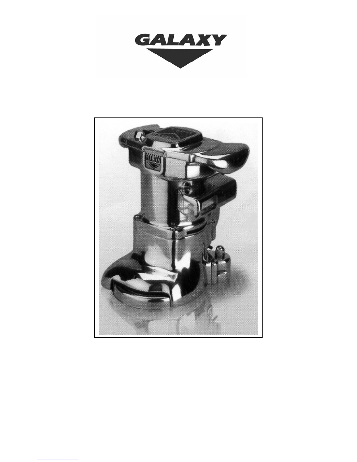
The On/Off Switch is on top of the sander. Turning the switch to “ON” starts the machine. Turning it
to “OFF” stops the machine.
The On/Off Switch
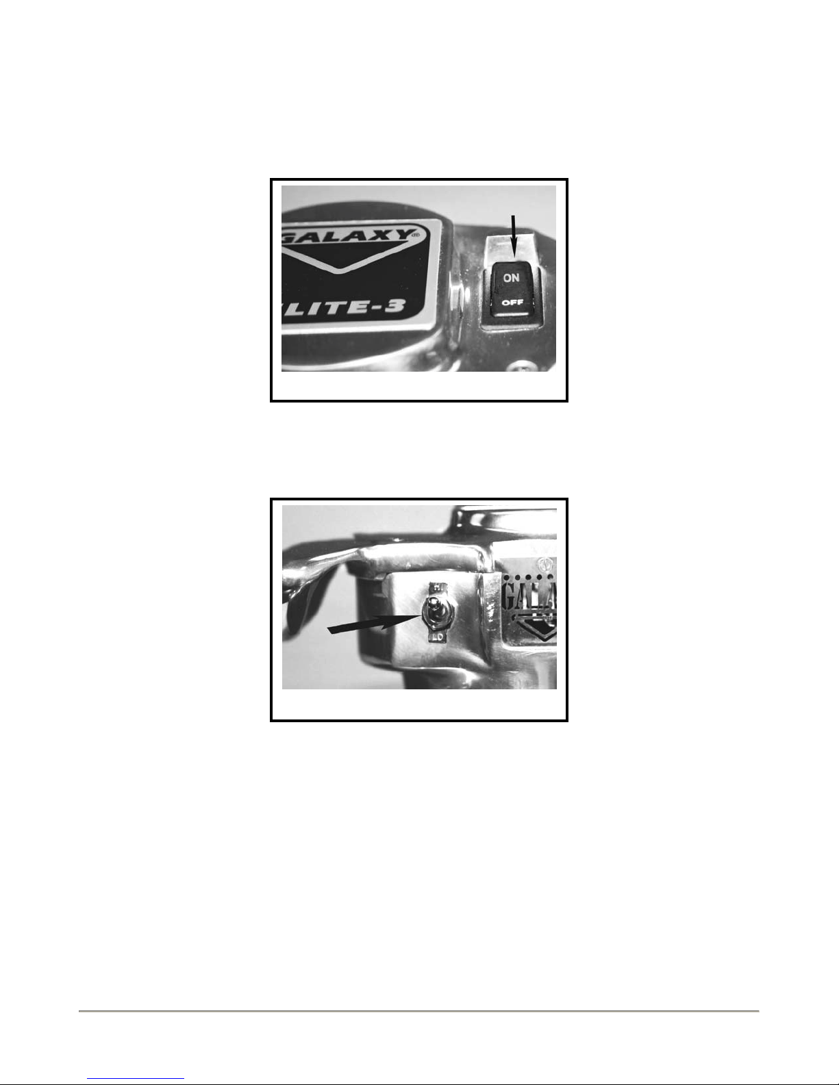
The Hi/Low Switch is on the top-left hand side of the machine. Turn it to “High” and the machine
runs at maximum speed. Turn it to “Low” and the machine runs at a lower speed.
Use the high-speed setting for faster wood removal. Use the low-speed setting for finish cuts and
custom work.
The Hi/Low Switch
Page 3 Galaxy Floor Sanding Machines, Operator’s Manual
Page 6
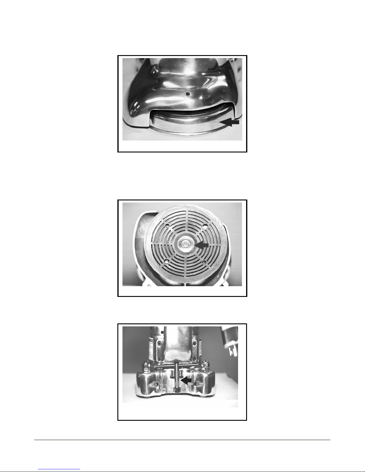
The Disc Guard is the lower casing that houses the sanding pad. It makes it possible to sand to the
edges of surfaces and along baseboards.
.
The Disc Guard
The Sandpaper Disc Holder is on the bottom of the sanding pad. It consists of a center bolt and
beveled washer and connects the sandpaper disc to the sanding pad.
The Sandpaper Disc Holder
The Special Wrench is held in the clamp on the back of the machine. It is used for changing the sandpaper
discs.
The Special Wrench
Page 4 Galaxy Floor Sanding Machines, Operator’s Manual
Page 7

g
The Dust Bag is a high quality dust collector. It has a special wear-reducing surface on its floor-facing
side. You can attach it to the output end of the dust pipe by using the bag’s attached drawstring. Check
to ensue the bag is securely attached and the drawstring is not loosely hanging. You attach the bag’s
inlet to the dust pipe, draw the string and tie it. You can also attach it with the supplied bag clamp. You
place the bag’s inlet over the dust pipe’s output end and attach the bag clamp.
The Dust Ba
HOW TO PREPARE THE MACHINE FOR OPERATION
Warning: Always make sure the power switch is in the “OFF” position and the machine is unplugged
from the electrical source prior to doing any maintenance.
How To Install Sandpaper Discs
Always use the right sized sandpaper discs. This unit requires 7” diameter paper with a 7/8”center hole. To
replace the sandpaper disc follow these steps:
• Take off the special wrench that is clamped to the back of the machine.
• Put the machine upside down.
• Use the special wrench and remove the center bolt and beveled washer of the sandpaper holder. (To
loosen turn it counterclockwise). Take off the used sandpaper disc and place a new one on the sanding
pad. Fasten it with the sandpaper holder.
Unscrewing the Center Bolt
Installing Sandpaper Disc
Page 5 Galaxy Floor Sanding Machines, Operator’s Manual
Page 8

Types of Sandpaper Discs
• If you want to remove surface coatings from old floors such as varnish, wax polishes and stain
use 12 Grit. Do not use it on new even floors!
• If you want to do a first sanding of a new even floor use 36 Grit. You can use also use it for a
second sanding of old wood floor.
• If you want to do a final sanding on a new or old wooden floor use 80 Grit.
• If you want a very fine finish on any kind of floor use 120 Grit.
How to Adjust the Angle of the Sanding Pad to the Floor
The goal is to adjust the angle of the Sanding Pad so its front center part slightly touches the floor.
The process is the same on both sides. Follow these steps:
• Make sure you are on a flat surface. Use a ¾” crescent or open-ended wrench to twist off the
cap nuts on top of each caster adjusting shaft. (Turn counterclockwise).
• Loosen the locking nuts to provide for adjustment. Fit a flat screwdriver into the screw-slot of
an adjusting shaft. Turn it clockwise to heighten the caster. This puts more pressure towards the
outer edge of the sanding pad. Turn it counterclockwise to lower the caster. This puts more
pressure towards the center of the sanding pad. Adjust both sides until you have the desired
angle.
• Tighten the locking nuts. (Turn clockwise).
• Replace the cap nuts.
Unscrewing Cap Nut
HOW TO OPERATE THE MACHINE
• Move the machine to your area of work. Inspect the area to ensure it is safe to work in. Remove
any obstacles and flammable substances. Use a hammer and punch to sink any floorboard nails.
• With the power switch in the “OFF” position connect the machine’s plug to the extension cord
and then to the electrical power source.
• Choose either the high or low speed position by flicking the high/low switch.
Page 6 Galaxy Floor Sanding Machines, Operator’s Manual
Operation Procedure
Angle Adjustment
Page 9

• Tilt the machine back by holding both handles so the sandpaper disc does not touch the floor.
• Put the power switch to the “ON” position.
• Keep the machine moving slightly from side to side as you lower the sandpaper disc to the
floor surface. Keep the machine moving as you sand the floor.
• Do not press down or apply weight to the machine. Its weight is sufficient for all types of
sanding.
Gradually Lower Sanding Pad to Floor
MAINTENANCE
Warning: Only trained people should do routine maintenance. Repairs should only be done
at authorized service centers.
Warning: Always turn the power switch to the “OFF” position and disconnect the machine’s
electrical plug prior to doing any maintenance.
The Dust Control System
If you do not remove the dust from the dust bag when it is 1/3 full it can decrease the efficiency of the
dust control system. Always remove the dust each time you finish using the machine.
Removing Dust Pipe Obstructions
• Turn the power switch to the “OFF” position and unplug the machine from its electrical power
source.
• Remove the dust bag and empty the dust in an outside containable garbage disposer.
• Remove the screws that attach the dust pipe to the machine’s casing.
• Remove the dust pipe and inspect it for any clogs or obstacles. Clean the dust pipe and its port.
• Re-install the dust pipe.
Page 7 Galaxy Floor Sanding Machines, Operator’s Manual
Page 10

Dust Pipe
How to Check and Replace the Carbon Brushes
The electric motor has two carbon brushes, one behind a front vent plate and the other behind a rear
vent plate. If replacement is required always replace both carbon brushes. Follow these steps:
• Turn the power switch to the “OFF” position and unplug the machine from its electrical power
source.
• Remove the screw on one of the vent plates. Slide it out of its grooved channel.
• Put your finger on the exposed metal tab. Push and release it to remove the Brush Holder
Spring. Pull on the copper shunt wire and the carbon brush will come out. Inspect it. If it is over
¼” in length and its wear is even it does not need to be replaced. Wipe it with a clean dry cloth
and push it back in. Push the Brush Holder Spring in and release it. It should stay locked in.
• If the carbon brush is less than ¼” in length or its wear is uneven it needs to be replaced. Pull
down on the wire as near as you can to the terminal. It will slide out. Reverse the procedure.
• Always replace both carbon brushes even if only one requires replacement.
Sliding Up the Vent Plate
Pushing the Brush Holder Spring
Page 8 Galaxy Floor Sanding Machines, Operator’s Manual
Page 11

How to Replace the Compact Florescent Light
• Turn the power switch to the “OFF” position and unplug the machine from its electrical power
source. Unscrew the two screws on the light housing.
• Take off the light housing.
• Pull the light straight out. It is clipped but with a little effort it comes out.
• Replace the light. Push and it will lock back in.
• Reattach the light housing.
Light Housing and screws
Replacing Light
Changing the Drive Belt (Follow the Five Sequences of Steps)
These Special Tools Are Required: Contact Your Dealer
Disc Removal Bar & Locking Nut
Remover
1. Remove the Sandpaper Disc.
2. Remove the Sanding Pad.
• Insert a screwdriver down and in-between two vacuum fan blades. This will be used to prevent
spin and create resistance while you unscrew the Sanding Pad with the Disc Removal Bar (Part
# 697). With one hand on the screwdriver and the other on the Disc Removal Bar turn the bar
counterclockwise while letting the screwdriver’s shaft jam tightly on the machine’s housing.
• Remove the Sanding Pad.
Page 9 Galaxy Floor Sanding Machines, Operator’s Manual
Page 12

Removing the Sanding Pad Using the Disc
Removal Bar & Screw Driver
Unscrewing the large Locking Nut with
Locking Nut Remover & Ratchet
3. Remove the exposed large Locking Nut and the Disc Guard.
• Use a wrench or ratchet on the Locking Nut Remover (Part #698) to unscrew the large Locking
Nut.
• Remove the large Locking Nut and the Disc Guard.
4. Take off the Belt Housing Plate.
• Unscrew the 5/32” Allen screws. Hand-tighten the large Locking Nut back on. You will use it
as a rim to pry up the Belt Housing Plate.
• With two large screwdrivers placed at about 180 degrees apart and inserted under the rim of the
Locking Nut gently push down with both hands. This acts as a lever. The Belt Housing Plate
will come up.
Unscrewing the Allen Screws
Prying up the Belt Housing Plate
Page 10 Galaxy Floor Sanding Machines, Operator’s Manual
Page 13

5. Replace the Drive Belt
• Insert a screwdriver in between two vacuum fan blades. Use a ¼” Allen key to remove the pinion
pulley. Turn counterclockwise. Remove the belt.
• To install the new belt wrap it around the pinion pulley. Make sure the teeth mesh with the
grooves. Slide the pinion back onto the armature shaft while sliding the belt onto the drive pulley.
Make sure the teeth mesh with the grooves. Retighten the pinion pulley.
• To put all the parts back together reverse the procedure.
Removing Pinion Pulley
Vacuum Fan Blades, Drive & Pinion
Page 11 Galaxy Floor Sanding Machines, Operator’s Manual
Page 14

Galaxy Elite 3 Wiring Diagram
Warning: Only people authorized by Galaxy Floor Sanding Machines should do repairs.
Electricity can injure and even kill you!
Page 12 Galaxy Floor Sanding Machines, Operator’s Manual
Page 15

Galaxy Elite 3 Edger Parts Drawing: Top of Machine
Page 13 Galaxy Floor Sanding Machines, Operator’s Manual
Page 16

Galaxy Elite 3 Edger Parts Drawing: Bottom of Machine
Page 14 Galaxy Floor Sanding Machines, Operator’s Manual
Page 17

Galaxy Elite 3 Edger Parts List
Reference # Description Part #
1 Plate – Name 621
2 Guard – Switch 613
3 Switch – On/Off 614
4 Housing – Top 601
5 Screw - 615
6 Screw – #10-24 x 1 S.S. Flat 616
7 Nut – ¼-20 617
8 Washer – Lock 618
9 Assembly – Brush Card 619
10 Spring – Brush 620
11 Brush – Motor 622
12 Screw - #8-32 x 1/2 126
13 Nut - #6-32 Lock 127
14 Screw - #6-32 x 3/8 258
15 Assembly – Lead Wire 623
16 Rectifier – Half Wave 624
17 Washer - #10 Flat 117
18 Screw - #10-24 x 3 Soc. Cap 625
19
20 Cover – Vent 627
21 Screw - #6-32 Flat 628
22
23 Nut – #10-32 Lock 205
24
25 Screw - #10-24 x 3/8 170
26 Screw – ¼-20 x 1 ½ S.S. 632
27 Washer – Lock S.S. 633
28 Housing – Field Assembly 602
29 Rivet – 5/32 x 5/8 634
30 Bulb – Compact Fluorescent 9W 635
31 Socket – Bulb 636
32 Screw - #10-24 x ½ Soc. Cap 86
33 Guard – Light 611
34 Lens – Light 638
35 Rivet – 1/8 x ¾ 639
36 Screw - #10-24 x ½ Soc. Cap 86
37 Bracket – Light Support 612
38 Insulator – Rubber 642
39 Label – Warning 643
40 Switch – High/Low 644
Page 15 Galaxy Floor Sanding Machines, Operator’s Manual
Field Assembly – 115v
Field Assembly – 230v
Ballast – 115v
Ballast – 230v
Ballast – 230v 50hz
Label – Specifications 115v
Label – Specifications 230v
626
726
629
729
730
630
731
Page 18

41 Plate – Hi/Lo 645
42 Nut – Retaining 646
43
44
45
46
47
48
Cord – Pigtail Assembly 115v
Cord – Pigtail Assembly 230v
Plug – 115v Male Twist Lock
Plug – 230v Male Twist Lock
Plug – 115v Straight Blade
Plug – 230v Straight Blade
Cord Assembly – 115v 50ft
Cord Assembly – 230v 50ft
Plug – 115v Female Twist Lock
Plug – 230v Female Twist Lock
Strain Relief - 115v
Strain Relief – 230v
49 Washer – Spring 654
50 Bearing – 6202 2RS C3 52
51
Armature Assembly - 115v
Armature Assembly – 230v
52 Key – 1/8 x 5/8 Woodruff 656
53 Ring – Retaining 657
54 Fan – Cooling 609
55 Baffle – Vacuum Fan 658
56 Fan – Vacuum 610
57 Seal – Dust 659
58 Bearing – 6202 2RS C3 52
Pinion Pulley – Complete 671
59 Spacer – Bearing 670
60 Pulley – Pinion 672
61 Housing – Belt 603
62 Clip – Wrench 673
63 Washer – Lock 674
64 Screw - #10-24 x ½ 675
65 Wrench 676
66 Washer – Spring 677
67 Shaft – Drive Pulley 678
68 Key – 1/8 x 5/8 Woodruff 656
69 Bearing – 6203 2RS C3 355
70 Belt – Drive 679
71 Pulley – Drive 680
72 Bearing – 6203 2RS C3 355
73 Ring – Retaining 362
74 Cover – Belt Housing 605
75 Screw – ¼-20 x 3/4 Flat Soc. Cap 268
76 Guard – Disc 606
77 Nut – Locking 682
78 Washer – Fiber 683
79 Pad – Sanding 684
647
747
648
748
649
749
650
750
652
752
653
753
655
755
Page 16 Galaxy Floor Sanding Machines, Operator’s Manual
Page 19

80 Washer – Paper Retaining 685
81 Bolt – Paper Retaining 686
82 Bag – Dust 687
83 Screw - #10-24 x ½ Soc. Cap 86
84 Pipe – Dust 604
85 Nut – ½-13 Cap Nut 688
86 Housing – Caster Assembly 607
87 Screw - #10-24 x ¾ 89
88 Nut – ½-13 Jam 689
Caster Assembly – Complete 691
89 Stud – Caster Swivel 690
90 Bearing – Swivel 629 2RSL 692
91 Yoke – Caster 608
92 Spacer – Wheel 693
93 Bearing – Wheel 608-8mm 2RSL 694
94 Wheel 695
95 Spacer – Wheel 693
96 Wheel 695
97 Bearing – Wheel 608-8mm 2RSL 694
98 Spacer – Wheel 693
99 Pin - Wheel 696
Disc Removal Bar (see page 9) 697
Locking Nut Remover (see page 9) 698
For parts or further assistance contact the manufacturer:
Galaxy Floor Sanding Machines
84 Northline Road
416) 285-6600
1(800) 263-5667
Fax: (416) 285-0506
www.galaxymachines.com
info@galaxymachines.com
Page 17 Galaxy Floor Sanding Machines, Operator’s Manual
Page 20

Galaxy’s Limited Warranty
Galaxy Floor Sanding Machines is the manufacturer and is hereafter referred to as “Galaxy.” The Galaxy
Elite 3 Edger, hereafter referred to as “the unit,” is warranted to be free from defects in materials and
workmanship for a period of one year from the date of purchase, when prepared, operated and maintained in
accordance with the instructions in Galaxy’s Elite 3 Edger Operator & Maintenance Instructions booklet and
the following Conditions of Warranty are met.
Conditions of Warranty
1. Registration: A completed Warranty Registration Card and a copy of the original sales receipt must have
been placed in the mail addressed to Galaxy within fourteen (14) days of the date of original purchase.
2. Original Registered Owner: This warranty only applies to the original registered owner. It is not
transferable upon resale.
3. Normal Wear: The warranty does not cover normal wear parts such as the drive belt and motor brushes.
It does not cover reasonable wear and tear to other parts of the unit.
4. Qualifications: Regardless of any statement Galaxy cannot determine a unit’s qualification for warranty
repair without physical inspection. The unit must not have been altered, modified or repaired by anyone
other than those authorized by Galaxy. The serial number on the unit must not have been altered or
removed. The unit must not have been subject to accident, misuse and abuse. It shall not have been let out or
used as a rental unit. Galaxy’s judgment in respect to the unit’s qualification for warranty repair is final.
5. Proper Delivery of a Unit: The owner must prepay the shipping charges to and from the repair
location(s). If accessories are sent with the unit they must be individually listed on the packing slips or
shipping documentation. Galaxy and/or its distributors shall not have any liability if there is a failure to
comply with these instructions.
6. Limitations: Galaxy’s liability under this warranty is limited to the repair of the unit and/or replacement
of its parts and is given to the original owner in lieu of all other remedies, including incidental and
consequential damages. There are no express warranties other than those specified herein. There are no
warranties beyond the description of the face hereof. No warranties, including but not limited to
merchantability, shall be implied.
Galaxy Floor Sanding Machines
84 Northline Road
Toronto, Ontario
Canada, M4B 3E5
(416) 285-6600
1(800) 263-5667
Fax: (416) 285-0506
www.galaxymachines.com
info@galaxymachines.com
Page 18 Galaxy Floor Sanding Machines, Operator’s Manual
 Loading...