

Page 1
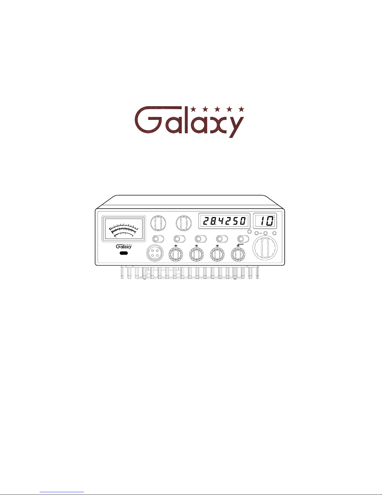
DX 95T2
10 Meter
Amateur Mobile Transceiver
With Built-in Frequency Counter &
StarLite Face Plate
OWNER’S MANUAL
KHz
+10
OFF
PWR
DX
4
0
BIG RIG SERIES
2
0
MOD
0
SWR
PWR
S
3
1
95T2
100
8
0
2
1.5
1
10
2
0
3
6
0
40
M
A
X
100
+20
60
7
5
80
9
+40
+60
dB
SWR
MOD
D
B
A
C
G
H
E
F
DIM POWER
OFF
PUSH
TB OFF F.DISP OFF
PUSH
MIC RF GAIN
TALKBACK
VOL SQ
RB
OFF
LOW
ECHO
AM
PA
FM USB
LSB
HI
MED
MOD
LAMP
PUSH
NB/ANL
RX
5/6 DIGIT
FINE COARSE
RX/TX
+10KHz
OFF
HIGH SWRALERT
ANL
NB
TB
Page 2

1
TABLE OF CONTENTS
PAGE
CHAPTER 1
Specifications .............................................. 2
CHAPTER 2
Installation ................................................ 3
Installing The Radio ........................................ 3
Ignition Noise Interference . . . ................................ 4
Antenna .................................................. 4
ExternalSpeaker ........................................... 4
Public Address . . . . . . . . . . . . . . . . . . . . . . . . . . . . . . . . . . . . . . . . . . . . 4
CHAPTER 3
Operation ................................................. 5
FrontPanel ............................................... 5
RearPanel ................................................ 9
Procedure to Receive and Transmit ............................ 10
Receiving SSB Signals . . . . .................................. 11
Alternate Microphone and Installation . . . . ...................... 13
Page 3

2
CHAPTER 1 SPECIFICATIONS
GENERAL
Model
Frequency Range 28.315 ~ 28.755 MHz
Emission FM/AM/USB/LSB
Frequency Control Phase-Lock-Loop (PLL) Synthesizer
Frequency Stability 0.001%
Temperature Range
-30°Cto+50°C
Antenna Impedance 50 Ohms
Antenna Connectors Standard SO-239 type
Input Voltage 13.8V DC
Size
73/4"(W)x27/8"(H)x101/4"(D)
Weight
6lb.
TRANSMITTER
AM/FM: 2W~50WRF Power Output
USB/LSB: 150W PEP
Spurious Emission -50 dB
Unwanted Sideband -50 dB
Audio Distortion 10%
Frequency Response 300 to 2500Hz
Microphone Dynamic
Clarifier Range
Coarse: ± 6.0KHz, Fine: ± 1.0KHz
RECEIVER
Sensitivity for 10 dB (S+N)/N AM: < 0.5 μV; USB/LSB: < 0.25 μV
Sensitivity for 12 dB (S+N)/N FM: < 0.25 μV
Squelch Sensitivity < 0.5 uV
Selectivity -55
Image Rejection -50 dB
AGC Figure of Merit 100 mV for 10dB Change in Audio Output
Audio Power Output 2.5W @ 10% Distortion
Audio Response 300 to 2500 Hz
(SPECIFICATIONS SUBJECT TO CHANGE WITHOUT NOTICE)
DX95T2
DB
Page 4

3
CHAPTER 2 INSTALLATION
INSTALLING THE RADIO
Choose a convenient location for operation that does not interfere with driver or
passenger. This radio is supplied with a universal mounting bracket. When
mounting the bracket and radio to your car, make sure it is mechanically strong.
Also, provide a good electrical grounding connection to the chassis of vehicle.
Proceed as follows to install the radio.
1. Locate a convenient area in your vehicle for the installation of the radio. Hold
the mounting bracket with the radio in the location where the radio is to be
installed. Make sure nothing will interfere with either the radio or the
mounting bolts. Mark and then drill holes for the mounting bracket.
2. Most radio antennas come equipped with a PL-259 plug. Connect this plug to
the ANT. Jack in the rear of the radio.
3. Extending from the rear of the radio is a fused red and black wire for the DC
connections to the vehicle’s electricalsystem. For best performance, it is
strongly recommended that the red lead be taken directly to the positive
terminal on the vehicle’s tery and thebat black lead be connected to the nearest
chassis ground. (Note: This radio is designed for vehicles with negative
ground systems.)
Connections should be made using appropriate “c p on”plugs of a size largerim
enough to make good contact with the bolt used to fasten to the battery and the
chassis ground. It is a good safety idea to install a second fuse that would
provide protection in case the red wire was to”f or get pinched and shortray"
to the body of the vehicle, somewhere between the battery and the radio.
High power radios such as this one require large DC current flow when in the
TX mode. Poor power connections cause supply voltage drops that can
substantially decrease the performance of your radio. A good DC connection is
probably one of the most important things for getting the best transmitter
performance and in some cases, least receiver noise.
4. Mount the microphone bracket near the radio in an easily accessible spot using
the two screws provided.
Page 5

4
IGNITION NOISE INTERFERENCE
With weak signals, you may experience interference of the signal by background
noise. This radio has NB and ANL circuits which will help reduce background
noise from sources such as your ignition system. However, background electrical
noise may come from several sources and all noise may not be eliminated. With
extremely weak signals, you can operate this radio with the engine turned off,
which should improve reception. If the ign ition noise level is too high to allow
proper operation under most conditions, you should have your installation of the
radio checked by a qualified technician.
ANTENNA
This radio has a jack in the rear for a standard PL-259 antenna plug. If you are
looking for the most range for your transmission, use a vertically polarized,
quarter-wave length antenna. If antenna height is a problem, you may use a shorter,
loaded-type whip antenna although you can expect some loss of transmission range.
To improve performance, your antenna should be matched to your radio. Your
antenna can be adjusted so that it matches your radio.
EXTERNAL SPEAKER
The external speaker jack (EXT SP.) on th e rear panel is used for remote receiver
monitoring. The external speaker should have 8 ohms impedance and be able to
handle at least 4 watts. When the external speaker is plugged in, the internal
speaker is disconnected.
PUBLIC ADDRESS
To use the Public Address (PA) function, first connect an external speaker to the
PA. SP. Jack on the rear of the radio. See the above specifications for a proper
external speaker. Keep the speaker away from the microphone to avoid acoustic
feedback.
Page 6

5
CHAPTER 3 OPERATION
CONTROL FUNCTIONS
FRONT PANEL
1. MOD LAMP: When switched on, this Modulation indicator will illuminate as
you speak into the microphone. When you speak louder, it appears bright
because it is on nearly 100 percent of the time and when you speak softer, it
appears dimmer because it is flickering on and off. It does not glow at all when
there is no modulation. This lamp operates in all modes.
2. SWR/MOD/PWR SWITCH: This switch controls the function of the meter
during the transmit mode. In the “S R” position, the meter indicates theW
Standing Wave Ratio (SWR) of your an tenna (accurate at maximum power
output). There are no adjustments because the SWR circuit in this radio
calibrates itself automatically. When the switch is in the “MOD position, the"
green scale on the meter indicates your percentage of modulation in the AM
mode only. It is most accurate when te sting at maximum power output. When
this switch is in “PWR” position, the meter indicates your power output.
3. MICROPHONE JACK: Used to connect microphone.
4. ON/OFF VOLUME CONTROL: This knob controls the volume and power
to the radio. To turn radio on, rotate the knob clockwise. Turning the knob
further will increase the volume of the receiver.
KHz
+10
OFF
PWR
DX
4
0
BIG RIG SERIES
20
MOD
0
SWR
PWR
S
3
1
95T2
100
8
0
2
1.5
1
10
2
0
3
6
0
40
M
A
X
100
+20
60
7
5
80
9
+40
+60
dB
SWR
MOD
D
B
A
C
G
H
E
F
DIM POWER
OFF
PUSH
TB OFF F.DISP OFF
PUSH
MIC RF GAIN
TALKBACK
VOL SQ
RB
OFF
LOW
ECHO
AM
PA
FM USB
LSB
HI
MED
MOD
LAMP
PUSH
NB/ANL
RX
5/6 DIGIT
FINE COARSE
RX/TX
+10KHz
OFF
HIGH SWRALERT
ANL
NB
TB
25
1714
15 16
21
1918 20
22
23
24
13
1 2
3
4
5
6 7 8 9
11 12
10
Page 7

6
5. SQUELCH CONTROL: This knob is used to eliminate background noise
being heard through the receiver, which can be disturbing when no
transmissions are being heard through the receiver. To use this feature, turn the
knob fully counterclockwise and then turn clockwise slowly until the
background noise is just eliminated. Further clockwise rotation will increase
the threshold level that a signal must overcome in order to be heard. Only
strong signals will be heard at a maximum clockwise setting.
6. MIC GAIN CONTROL/PUSH TB OFF SWITCH: Adjusts the microphone
gain in transmit and PA modes. This controls the gain to the extent that full
talk power is available several inches away from the microphone. In the Public
Address (PA) mode, the control functions as the volume control. Pushing this
knob turns the Talkback circuit on and off.
7. RF GAIN CONTROL:
8. DIM CONTROL/PUSH FREQUENCY DISPLAY OFF SWITCH: This
knob controls the level of brightness for the meter lamp, faceplate, frequency
display and channel display. Pushing this knob turns the Frequency Display on
and off
9. RF POWER CONTROL: This control allows the user to adjust RF power
output.
10. COARSE/FINE CONTROL/PUSH NB-ANL OFF SWITCH: Allows
variation of the radio operating frequencies above and below the channel
frequency. Although this control is intended primarily to tune in SSB signals,
it may be used to optimize AM/FM signals. Pushing this knob turns the Noise
Blanker (NB) / Automatic Noise Limiter (ANL) circuit on and off. The Noise
Blanker (NB) is very effective in eliminating repetitive impulse noise such as
ignition interference.
11. RX/TX/OFF/RX SWITCH: When in the RX/TX position, the two clarifiers
(Coarse and Fine) function on both receive and transmit. When the switch is in
the RX position, the Fine clarifier fu nctions on receive only and the Coarse
clarifier still functions on both receive and transmit. When in the OFF position,
both clarifiers have no effect on the frequency.
12. CHANNEL SELECTOR: This control is used to select the desired transmit
and receive channel.
13. TB LED: This LED lights green when the TB function is on.
Adjust this knob for desired level of incoming signal.
Page 8

WARRANTY
This radio is covered by a two
year Limited parts and labor
warranty.
※ "Limited” means that we will repair problems caused by factory defects or
normal use at no charge.
※ Before returning a radio to us for warranty service, please call our Service
Department for a Repair Authorization Number (RAN). This RAN must be
written below your return address on the outside of the shipping box. Boxes,
which arrive without an RAN, will be refused, and the shipping company will
return the unopened box to you. Be sure to have a pen and paper ready along
with the serial number of your radio before calling. We will give you the RAN
and our shipping address over the phone. The telephone number of the Service
Department is (760) 480-8800, and we suggest calling between 10:00 AM and
4:00 PM Pacific Time.
※ Please include a note with a detailed description of the symptoms. This is
important because it will help the technician who works on your radio to locate
your problem. Intermittent problems are easily overlooked, so be sure to give
as much detail as possible in your no te. Also, please include your daytime
telephone number in case our technicians have any additional questions.
※ Do not send your power cord or microphone unless we ask for these items
during our telephone conversation.
※ You are responsible for getting the radio safely to us. (We suggest using
United Parcel Service.) You must pay to ship the radio to us, and we will pay
to ship the radio back to you. Since we use UPS and they do not ship to Post
Offices boxes, please provide us with a street address for the return of your
radio.
※ We will repair and return your radio as soon as we can. We appreciate your
choosing a Galaxy radio and we want you to be on the air as much as possible!
Be sure to visit our web site at
www.GalaxyRadios.com
Page 9

Printed in Taiwan
AT0949010R
 Loading...