

Page 1

Pub. 42004-479B
GAI-TRONICS® CORPORATION
A HUBBELL COMPANY
Telephone Management Application
(TMA) User Guide
T ABLE OF C ONTENTS
Confidentiality Notice .....................................................................................................................1
Introduction .....................................................................................................................................1
Starting TMA...................................................................................................................................2
Creating a New Database File ................................................................................................................ 3
Opening an Existing Database File........................................................................................................ 4
Database Back-up Information ............................................................................................................. 4
TMA Database Archives ........................................................................................................................ 4
TMA Database.................................................................................................................................5
TMA Database Structure ....................................................................................................................... 5
TMA Icons ............................................................................................................................................... 6
TMA Template Phones ........................................................................................................................... 7
Selecting the Template Phone Record .................................................................................................................. 8
Adding a Group to TMA Database ....................................................................................................... 9
Adding Phones to TMA Database ....................................................................................................... 10
Preparing the First Phone Record (excludes GAI-Tronics VoIP Phones) .......................................................... 10
Manual Entry ...................................................................................................................................................... 11
Auto-Discovery ................................................................................................................................................... 15
Copying a Phone Record .................................................................................................................................... 18
Import ................................................................................................................................................................. 21
Managing Phone Records ............................................................................................................23
Phone Management Form .................................................................................................................... 23
Phone Properties Area......................................................................................................................................... 24
Phone Data .......................................................................................................................................................... 24
Command Area ................................................................................................................................................... 25
Synchronization Area.......................................................................................................................................... 25
Example --Typical Phone Record Setup ............................................................................................................. 26
Phone Properties Area .......................................................................................................................... 27
General ................................................................................................................................................................ 27
Behavior .............................................................................................................................................................. 29
Call-In Configuration .......................................................................................................................................... 32
Fault Indicators ................................................................................................................................................... 33
Memory Configuration ....................................................................................................................................... 38
Cascading Autodial Numbers ............................................................................................................................. 39
Valid Autodial Numbers ..................................................................................................................................... 39
Type A Advanced Settings ................................................................................................................................. 39
GAI-Tronics Corporation 400 E. Wyomissing Ave. Mohnton, PA 19540 USA
610-777-1374 800-492-1212 Fax: 610-796-5954
V
ISIT WWW.GAI-TRONICS.COM FOR PRODUCT LITERATURE AND MANUALS
Page 2

T ABLE OF CONTENTS PUB. 42004-479B
GTL SMART Phone Properties .......................................................................................................... 44
General ................................................................................................................................................................ 44
Behavior .............................................................................................................................................................. 46
Call-In ................................................................................................................................................................. 48
Memories ............................................................................................................................................................ 49
Sensor/Faults ....................................................................................................................................................... 51
VoIP Phone Properties Form ............................................................................................................... 52
Command Buttons .............................................................................................................................................. 52
GAI-Tronics VoIP Phone Properties .................................................................................................. 53
General ................................................................................................................................................................ 53
Configuration ...................................................................................................................................................... 55
Changing Phone Records ..................................................................................................................... 57
Moving a Phone Record ...................................................................................................................................... 57
Deleting a Phone Record .................................................................................................................................... 57
Polling Phones ..............................................................................................................................58
Polling Setup Form ............................................................................................................................... 59
Filter Field .......................................................................................................................................................... 59
Available Phones List ......................................................................................................................................... 60
Polling List .......................................................................................................................................................... 60
Add/Remove Buttons .......................................................................................................................................... 60
Polling Control Area ........................................................................................................................................... 61
Monitoring In-Progress Communications ...................................................................................62
Multiple Phone Update .................................................................................................................65
Multiple Phone Update Wizard ........................................................................................................... 65
Viewing Call-in or Poll Schedules ...............................................................................................72
Viewing a Call-in Schedule .................................................................................................................. 72
Viewing a Poll List ................................................................................................................................ 74
TMA Status Reporting ..................................................................................................................76
Status Report Window Tabs ................................................................................................................ 77
Fields Drop-Down List Selections ...................................................................................................................... 80
Criteria Drop-Down List Selections ................................................................................................................... 81
Creating Reports ................................................................................................................................... 82
Maintenance (Poll) Calls Report ......................................................................................................................... 82
Polling Exceptions Report .................................................................................................................................. 87
Call In Report...................................................................................................................................................... 91
Inactive Phone Report ......................................................................................................................................... 94
VoIP Alarm Notification Report ......................................................................................................................... 98
Configuring Reports ........................................................................................................................... 102
Type A/Type B Exceptions Options Report Window ....................................................................................... 102
Automated Reports ........................................................................................................................................... 105
Default Automated Reports .............................................................................................................................. 107
Custom Automated Reports .............................................................................................................................. 108
E-mail Setup ................................................................................................................................111
General Options .................................................................................................................................. 112
SMTP Settings ..................................................................................................................................... 113
E-mail Addresses ................................................................................................................................. 113
GAI-Tronics Corporation 400 E. Wyomissing Ave. Mohnton, PA 19540 USA
610-777-1374 800-492-1212 Fax: 610-796-5954
V
ISIT WWW.GAI-TRONICS.COM FOR PRODUCT LITERATURE AND MANUALS
Page 3

T ABLE OF CONTENTS PUB. 42004-479B
Custom E-mail for Critical Faults ..................................................................................................... 113
Placing Phones In or Out of Service ..........................................................................................114
Placing a Phone “Out of Service” ...................................................................................................... 114
Placing a Phone Back In Service ....................................................................................................... 115
TMA Options ...............................................................................................................................116
Communication Window .................................................................................................................... 116
Actions Window .................................................................................................................................. 118
Graphical Window .............................................................................................................................. 120
Maintenance Log ........................................................................................................................121
Maintenance Log Template................................................................................................................ 122
Adding an Entry to Maintenance Log ............................................................................................................... 122
Reviewing Records ........................................................................................................................................... 123
Troubleshooting ..........................................................................................................................124
Recommended Spare Parts .........................................................................................................127
Definitions and Acronyms ..........................................................................................................127
GAI-Tronics Corporation 400 E. Wyomissing Ave. Mohnton, PA 19540 USA
610-777-1374 800-492-1212 Fax: 610-796-5954
V
ISIT WWW.GAI-TRONICS.COM FOR PRODUCT LITERATURE AND MANUALS
Page 4

Pub. 42004-479B
GAI-TRONICS® CORPORATION
A HUBBELL COMPANY
Telephone Management Application
(TMA) User Guide
Confidential ity Notice
This manual is provided solely as an operational, installation, and maintenance guide and contains sensitive
business and technical information that is confidential and proprietary to GAI-Tronics. GAI-Tronics retains
all intellectual property and other rights in or to the information contained herein, and such information may
only be used in connection with the operation of your GAI-Tronics product or system. This manual may
not be disclosed in any form, in whole or in part, directly or indirectly, to any third party.
Introduction
The GAI-Tronics Telephone Management Application (TMA) is used to monitor the activity and
health of GAI-Tronics RED ALERT
information provided by TMA can prove useful in reducing maintenance labor costs and greatly reduce
liabilities typically associated with an emergency communication system.
®
, SMART Industrial, and VoIP/WiFi Telephones. The reports and
OTE: All references to “telephones” in this document are understood to be GAI-Tronics RED ALERT
N
SMART Industrial, or VoIP/WiFi Telephones.
TMA runs continuously on a dedicated personal computer by using one (or more) telephone line
compatible modems or a Local Area Network (LAN) to gather status information from each telephone at
regular intervals. In addition, the System Manager uses TMA to remotely adjust the behavior of
individual telephones. These updates are either sent to the phone immediately or are held to be sent
during the next scheduled health-check maintenance call.
TMA provides an at-a-glance view of the status of the telephones as well as customizable reporting in the
form of scheduled printed reports, and reports generated on demand.
For questions about TMA, please contact:
Service Group
GAI-Tronics Corporation
400 E. Wyomissing Avenue
Mohnton, PA 19540
800-492-1212 (8 a.m. to 5 p.m. EST) 610-777-1374 outside the USA
®
,
GAI-Tronics Corporation 400 E. Wyomissing Ave. Mohnton, PA 19540 USA
610-777-1374 800-492-1212 Fax: 610-796-5954
V
ISIT WWW.GAI-TRONICS.COM FOR PRODUCT LITERATURE AND MANUALS
Page 5
Pub. 42004-479B
Telephone Management Application (TMA) User Guide Page 2 of 128
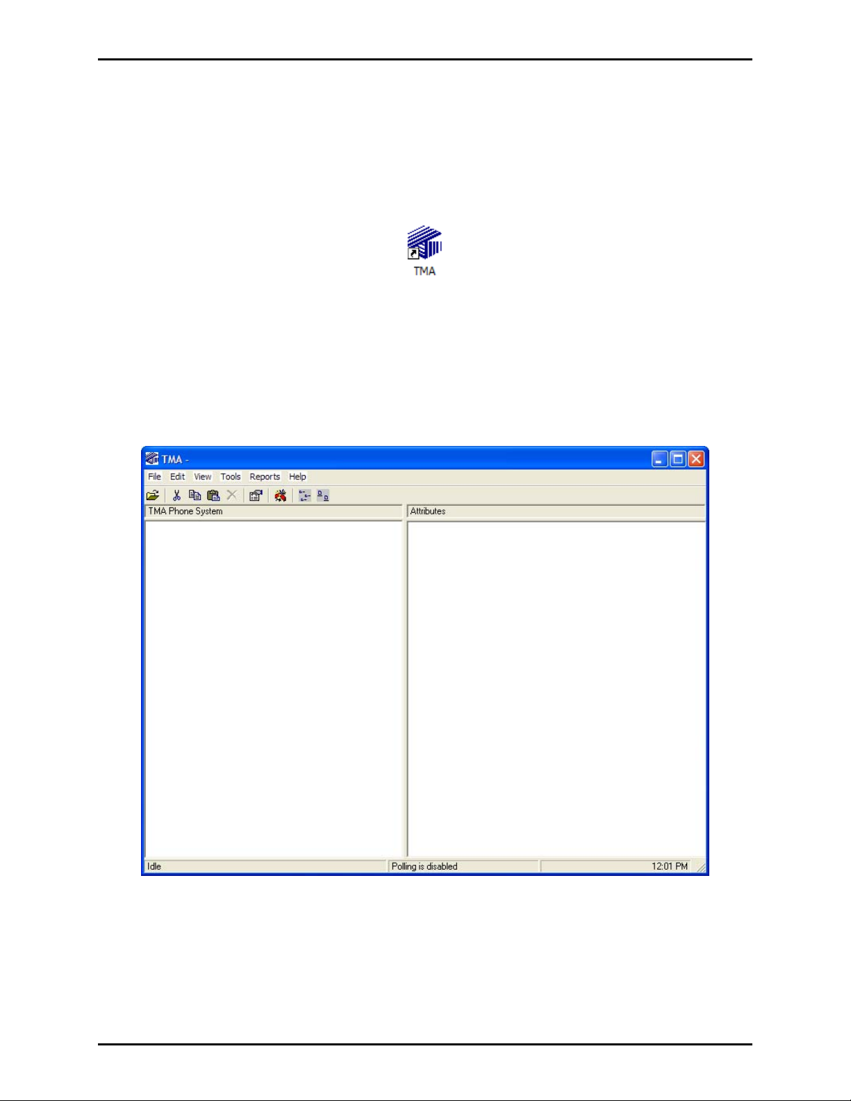
Starting TMA
TMA can be started (or re-started) after installation of the software, the security key has been inserted into
a USB port, and at least one telephone icon appears in the Windows taskbar notification area. Refer to
GAI-Tronics Pub. 42004-478. To start TMA, double click the desktop TMA icon with the GAI-Tronics
logo (shown below) or start the application via the Windows Start menu. The path is
Programs > TMA
.
TMA Desktop Icon
When TMA is initially started, it will display a “No Current Database” dialog box over the startup splash
screen, indicating TMA was not able to open the most recently used telephone database. This occurs
because the recently used database name is undefined for this new TMA installation.
Start > All
Read the dialog box, and then select
and pull-down menu selections for F
OK to dismiss it. The TMA window will now contain empty panels,
ILE, EDIT, VIEW, etc., as shown below.
e:\standard ioms - current release\42004 instr. man uals\42004-479b.doc
03/14
Page 6
Pub. 42004-479B
Telephone Management Application (TMA) User Guide Page 3 of 128
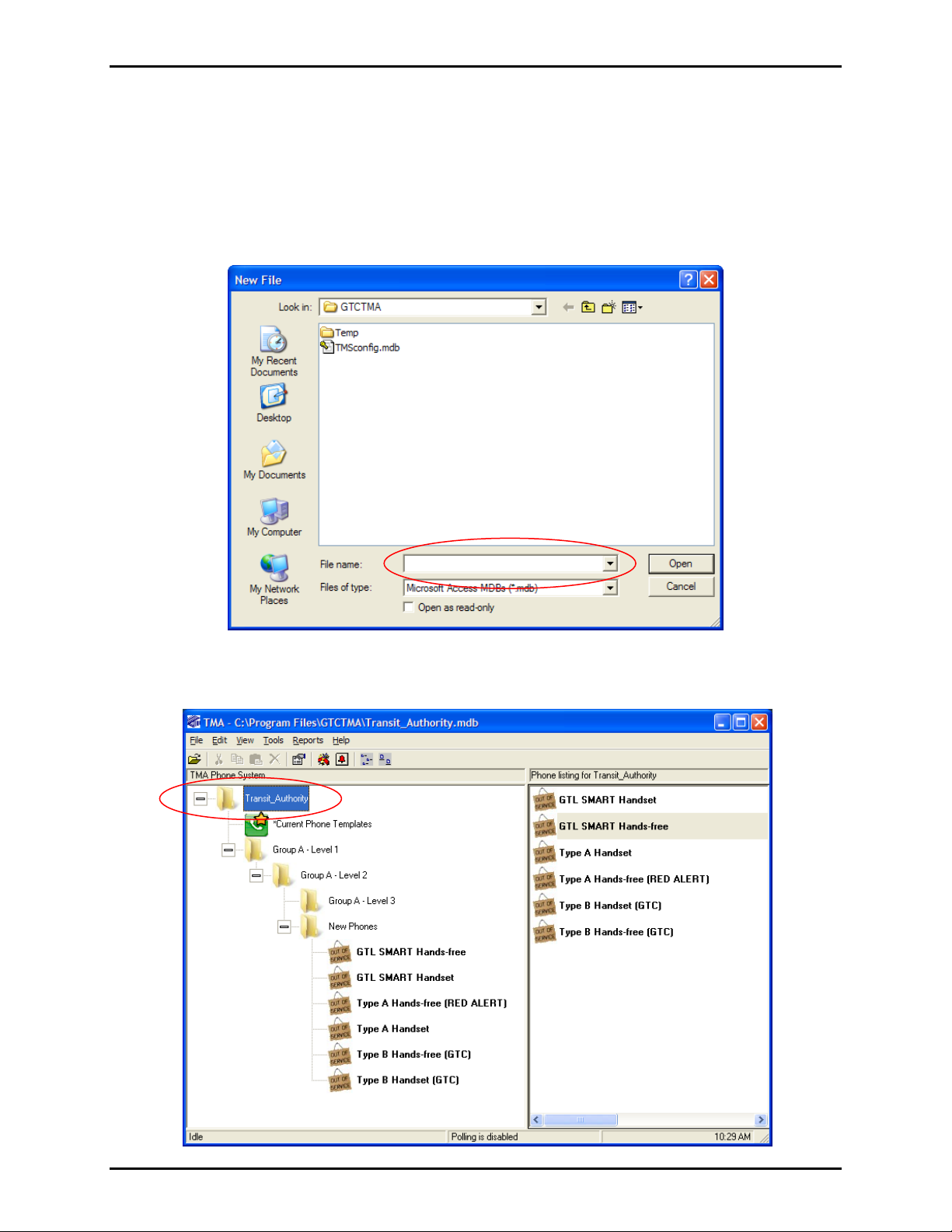
Creating a New Database File
All SMART Telephone information relating to the site is contained in a TMA database. To create a new
database file, select
below.
In the “File name” field, type the site name of the database such as “University E-Phones”, or, “Transit
Authority Phones”. Do not type the file extension “.mdb” since the system will add this automatically.
File, then New from the menu. The “New File” dialog box will appear, as shown
Click Open and the following window will appear with the site name at the Domain Level, as shown
below.
e:\standard ioms - current release\42004 instr. man uals\42004-479b.doc
03/14
Page 7

Pub. 42004-479B
Telephone Management Application (TMA) User Guide Page 4 of 128
Opening an Exis ting Database Fi le
To open the TMA database to access an existing file, select File, then Open in the menu bar. This will
display Open File window, as shown below.
In the Open File window, ensure the
select the appropriate file name with an .mdb file extension from the list, and click
N
OTE: Do not open the file TMSconfig.mdb since this database is used for processing directives.
GTCTMA folder name appears in the Look in: field at the top, then
Open.
Database Ba ck-up Info rmation
TMA uses a single database file to store phone information, configuration data, voice call and data call
information for all telephones. The database is normally stored in the folder C:\Program
Files\GTCTMA. As with other important documents or files, a backup copy of the database file should
be created at regular intervals.
The initial file size is approximately 600 kb. The file size for a system containing 40 phone records will
grow to approximately 2 Mb over a 60-day interval. TMA archives older telephone data every month.
TMA Database Archi ves
At noon on the first day of each month, TMA creates an archive database. The archive database will
contain all call data that is more than 30 days old along with all current phone configuration data. Any
data less than 30 days old will remain in the current database. The archive database file is assigned the
name of the current database followed by mmddyyarc where “mmddyy” denotes the month, day and
year when the archive was created and “arc” denotes that is an archive file.
With this database archive process, the size of the active database is kept reasonably small to maintain
high data processing efficiency. The archive process only takes a few minutes, and the active database is
also compacted. All archived database files are directly compatible with TMA and can be accessed in the
same manner as any other database.
e:\standard ioms - current release\42004 instr. man uals\42004-479b.doc
03/14
Page 8
Pub. 42004-479B
Telephone Management Application (TMA) User Guide Page 5 of 128
TMA Databa se
The TMA database must contain one phone record for each supervised telephone on site. Information
contained in this section explains how the TMA database is structured and how phone records are added
into the database, based on demographics of the site or facility.
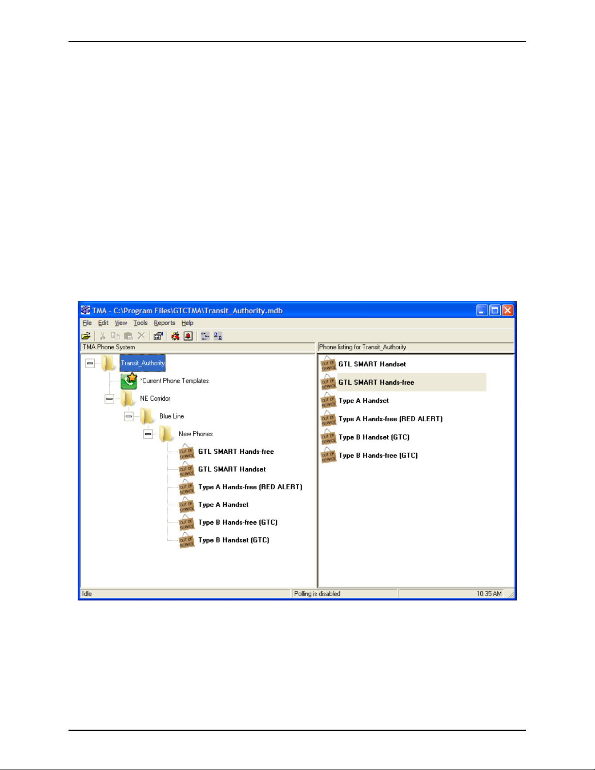
TMA Database St ructure
Phone records are organized in a tree structure with a “domain” as the highest level in a system
configuration. The domain is typically the name of the site or facility. Beneath the domain there are
three “group levels” used to organize the phones. Each level provides the means to organize the
telephone system within the tree structure. Individual phone records are always contained in group
level 3.
When planning a system, considerations should be given to the physical geographic locations of the
telephones, physical telephone lines, the types of telephones in the system, and the administrative process
of assigning phone maintenance tasks. Careful planning facilitates the use of the many sorting options
provided by the TMA reports.
Domain Name – is the highest level and is generally the name of the site or facility.
└ Group Level 1 – can be a satellite location or region, e.g., North or South Campus.
└ Group Level 2 – is typically an area within a satellite location or region, e.g., Northeast quadrant
└ Group Level 3 – is the lowest level where individual telephones reside (a building or area).
e:\standard ioms - current release\42004 instr. man uals\42004-479b.doc
03/14
Page 9
Pub. 42004-479B
Telephone Management Application (TMA) User Guide Page 6 of 128
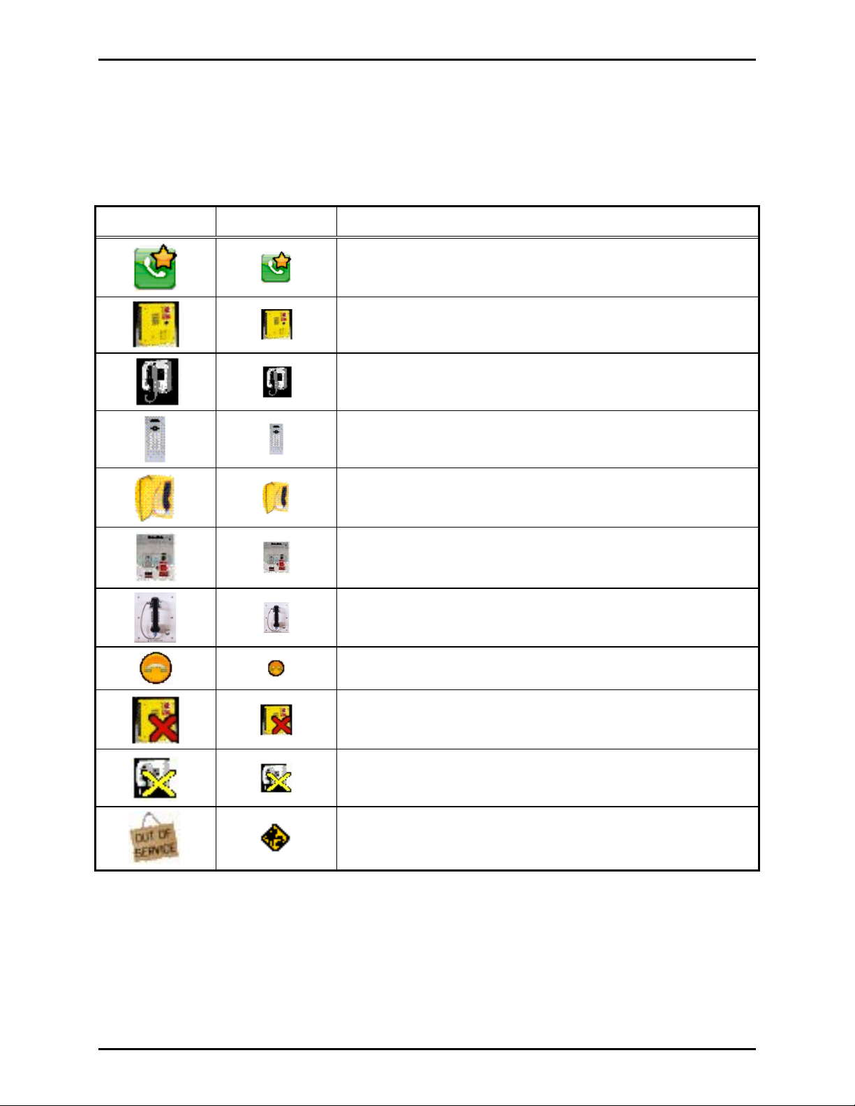
TMA Icons
For each phone and template phone in the system, TMA displays an icon for quick recognition of each
phone’s status. Icons displayed in TMA are shown below.
Table 1. TMA Icons
Large Icon Small Icon Description
Type B Hands-free Phone Icon (formerly called GTC)
Type B Handset Phone Icon (formerly called GTC)
GTL SMART Hands-free Phone Icon
GTL SMART Handset Phone Icon
Current Phone Templates Icon
®
Type A Hands-free (RED ALERT
) Phone Icon
Type A Handset Phone Icon
GAI-Tronics VoIP Phone Icon
Icon with a yellow “X” is a Phone with Exceptions
Icon with a red “X’ is an Inactive Phone
Out of Service Icons
e:\standard ioms - current release\42004 instr. man uals\42004-479b.doc
03/14
Page 10

Pub. 42004-479B
Telephone Management Application (TMA) User Guide Page 7 of 128
TMA T emplate Phones
Each new TMA database includes six phone records, one for each telephone type (excluding GAI-Tronics
VoIP Phones). Each phone record is tagged as the template phone that TMA uses to create additional
phone records in the database. The six template phone records correspond to the different types of
telephones manufactured by GAI-Tronics. A template phone record is always shown with its description
in bold text. The initial phones present in a new database are displayed in the main window as:
Table 2. GAI-Tronics Telephone Type Identification
Telephone Type Models
Hands-free Telephones
Type A Hands-free
(RED ALERT
®
)
Type B Hands-free (GTC)
GTL SMART Hands-free
Handset Telephones
Type A Handset
39x-00x
39xAL-00x
Telephones using 69577 PCBA
29x-003
29xAL-003
Telephones using 69411 PCBA
29xSL
29xALSL
Telephones using 69385 PCBA
VR
DDA
Help Point
Hygeia
2x6-005
2x7-005
Telephones using 69577 PCBA
Type B Handset (GTC)
2x6-003
2x7-003
Telephones using 69411 PCBA
GTL SMART Handset
2x6S
2x7S
Telephones using 69285 PCBA
Titan
Commander
e:\standard ioms - current release\42004 instr. man uals\42004-479b.doc
03/14
Page 11
Pub. 42004-479B
Telephone Management Application (TMA) User Guide Page 8 of 128
Each template phone can be configured and saved in the same way as other phone records are updated.
Each phone record (including those tagged as the “Template”) contains information such as emergency
auto-dial phone numbers, a voice call time limit, TMA call-in phone numbers, a call-in schedule, and
more. The designated template phone is used when phones are added to the database either manually,
through the Auto-Discovery feature, or through the Import feature, each of which is detailed in the
sections that follow. A phone record that is set as a template can be configured and saved, but cannot
be
deleted.
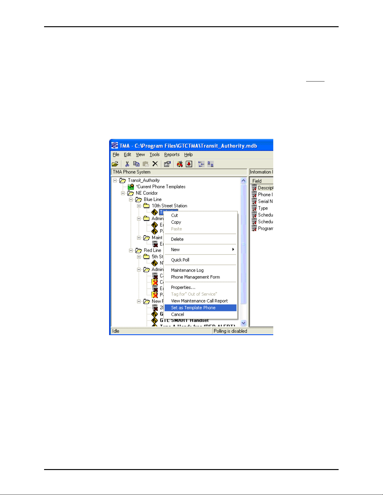
Selecting the Template Phone Record
Any phone record can be selected to be the template for its telephone type. To designate a phone record
as the template phone, right click on the telephone icon and select
Set as Template Phone.
e:\standard ioms - current release\42004 instr. man uals\42004-479b.doc
03/14
Page 12
Pub. 42004-479B
Telephone Management Application (TMA) User Guide Page 9 of 128
Adding a Group to TMA D atabase
Adding another group to the TMA database is done manually, and can only be done at the Domain Name
Level, or at Group Levels 1 or 2. The following explains how to add a group.
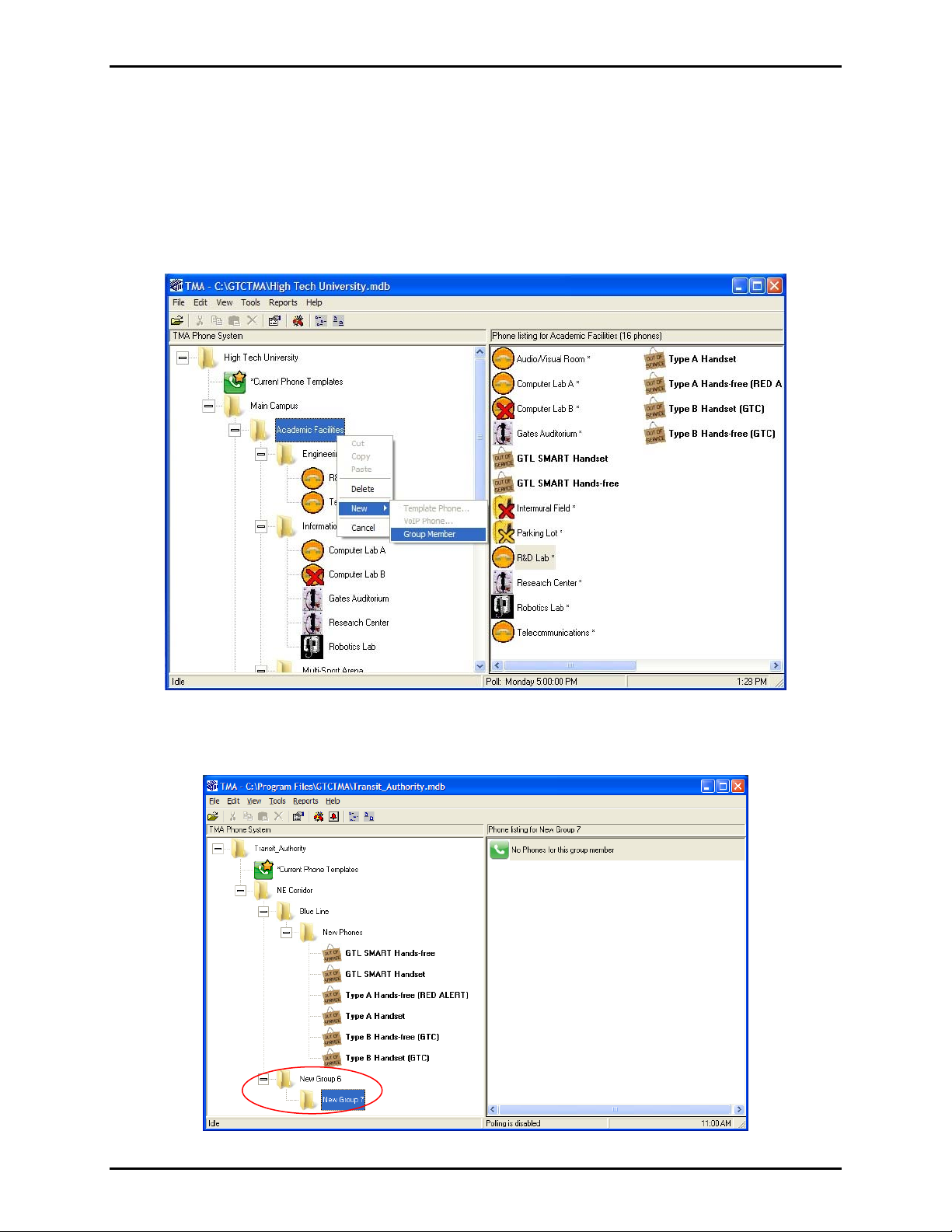
To add another group, right click on the group level name where the new group (or sub-group) is to be
placed. A pop-up menu will appear as shown below. Move the cursor to highlight
select
Group Member in the fly-out box.
New ► and then
Upon clicking on “Group Member,” the next screen shows the “New Group” added to the phone tree list.
In this example, another Level 2 group is added, a new Level 3 group is also added.
e:\standard ioms - current release\42004 instr. man uals\42004-479b.doc
03/14
Page 13
Pub. 42004-479B
Telephone Management Application (TMA) User Guide Page 10 of 128
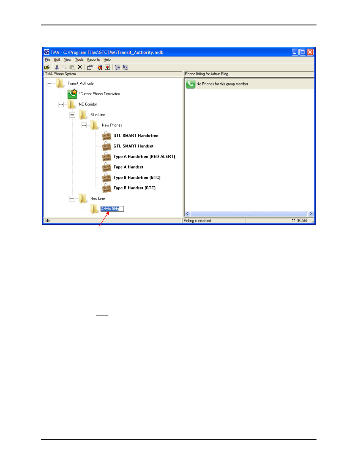
To rename any group, select and click on the group name and type the new name in the box.
Adding Phones to TMA Da tabase
Adding phone records to the TMA database can be done by several methods: manual entry, AutoDiscovery, copy, or import. Each method is explained below:
Preparing the First Phone Record (excludes GAI-Tronics VoIP Phones)
The first phone record included in a new database is tagged as the template phone for its telephone type.
A template phone record will be copied repeatedly to create new phone records. It is important to specify
the required settings prior
records do so by making copies of the template phone record.
1. Identify the type of telephone(s) that are being added to the system using Table 2 as a reference.
2. Right click on the template phone record of this type in the TMA database. (The description of each
template phone is shown in bold text.)
3. Select
Phone Management Form. Consult the section “Managing Phone Records” on page 23.
4. Specify the AutoDial phone numbers (and any other settings required). Refer to the “Memory
Configuration” section on page 38.
to making many copies of this record. All methods that can be used to add new
5. Select
Send and Synchronize Later, then click Apply, then click OK. This adjusts the settings of the
template phone record.
OTE: Changes made to the template phone record will carry over into every new phone record created.
N
e:\standard ioms - current release\42004 instr. man uals\42004-479b.doc
03/14
Page 14
Pub. 42004-479B
Telephone Management Application (TMA) User Guide Page 11 of 128
Manual Entry
A phone record that is manually entered is a copy of the template phone for the selected phone type,
except in the case for GAI-Tronics VoIP Phones which do not have a default template. The New Phone
Wizard can create up to ten phone records each time it is run.
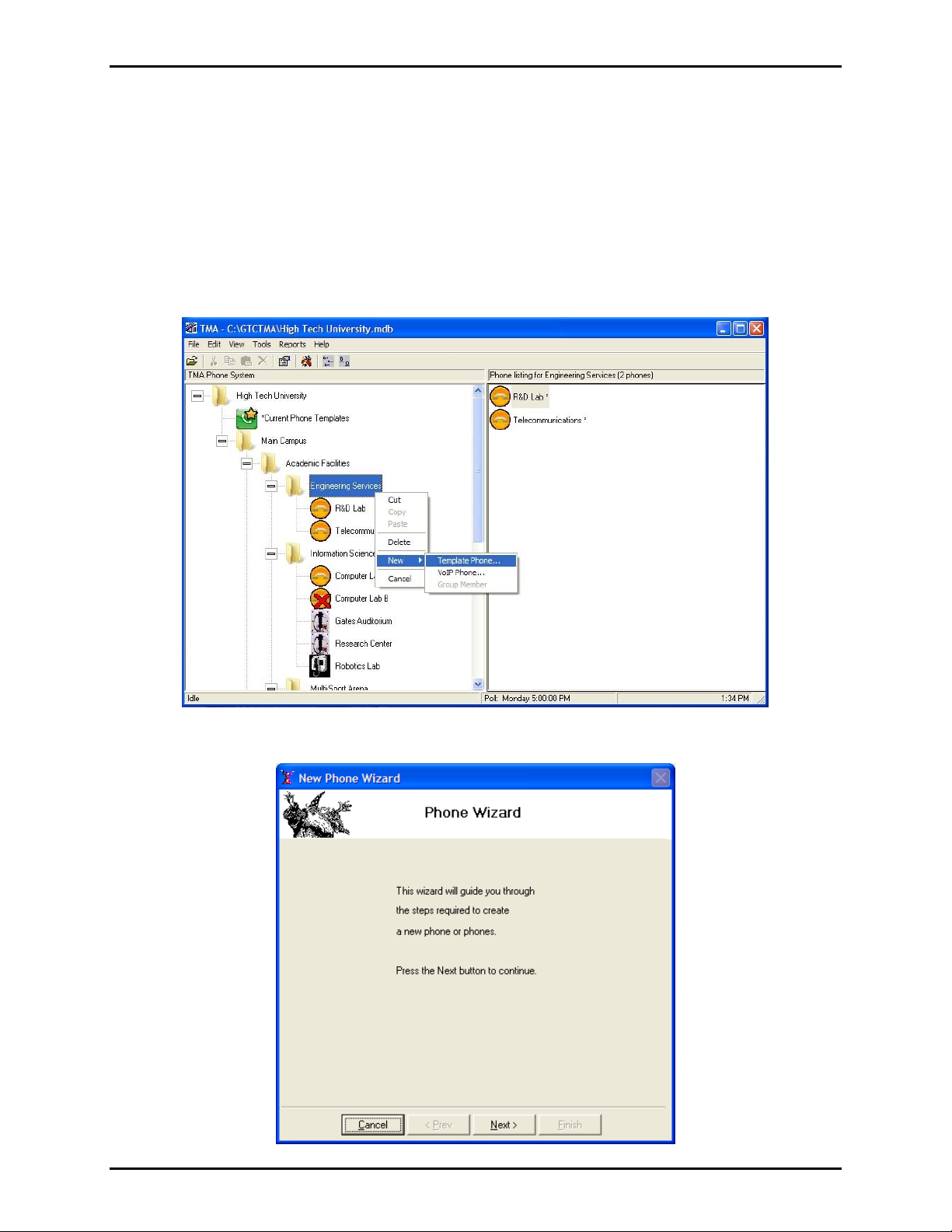
To add a phone record using the New Phone Wizard, right click on the group name where the phone
record is to be placed. A pop-up menu will appear as shown below. Move the cursor to highlight
New ►
and then select Template Phone… in the fly-out box. In this example, a phone record is being added to
the “Engineering Services” group. To add a VoIP phone, simply follow the same procedure and select
VoIP Phone which will bypass the New Phone Wizard and create the phone in the selected group.
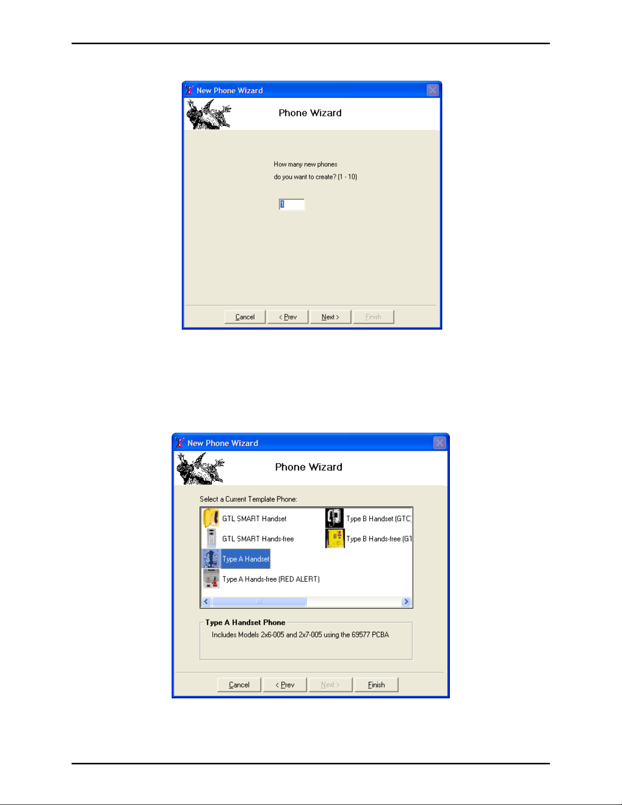
The Phone Wizard window will appear; it allows for creation of one or more phone records.
e:\standard ioms - current release\42004 instr. man uals\42004-479b.doc
03/14
Page 15
Pub. 42004-479B
Telephone Management Application (TMA) User Guide Page 12 of 128
Click Next > to continue.
.
Select the number of phones to be created in this group and click
Next > to continue.
In the next window, choose the type of the phone to be added to the database. The available SMART
phone record types are divided into those equipped with a handset and those without a handset (handsfree). Refer to Table 2, which lists the model numbers (by series) to select the type that matches the
SMART Telephones being installed.
Click
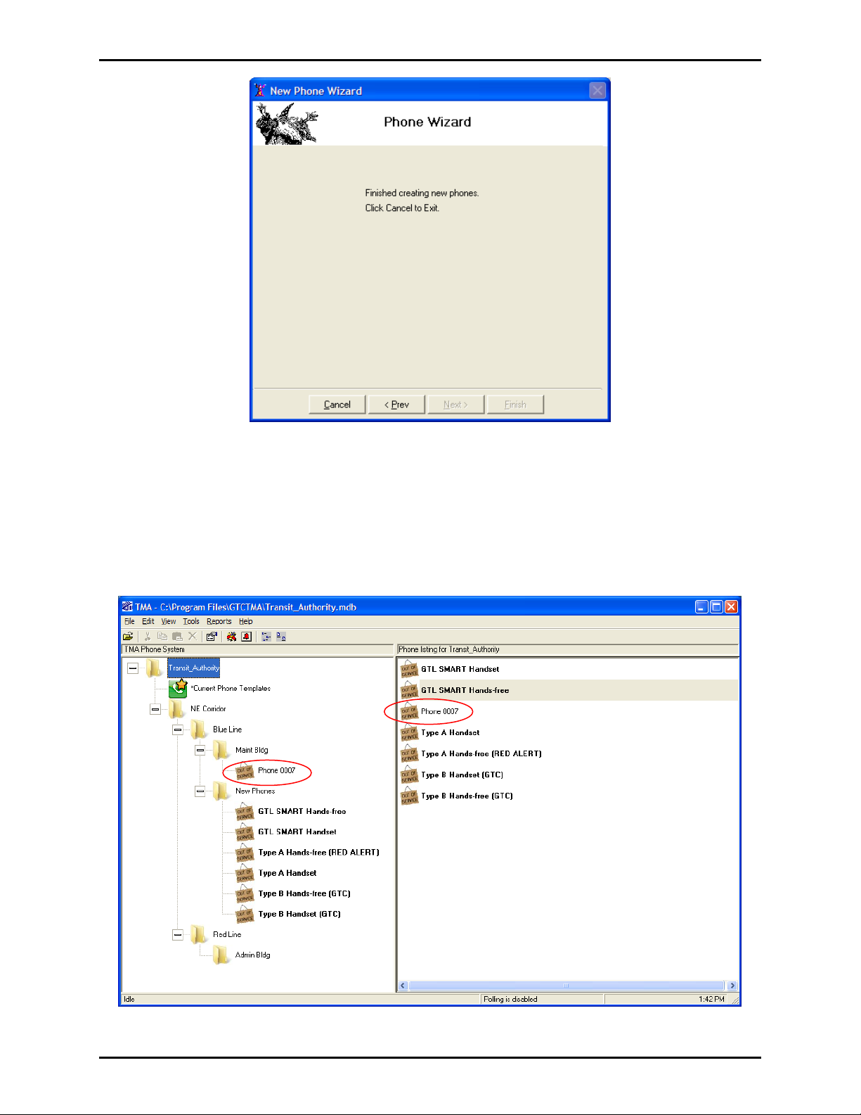
Finish. The Phone Wizard adds the new phone records to the database.
e:\standard ioms - current release\42004 instr. man uals\42004-479b.doc
03/14
Page 16
Pub. 42004-479B
Telephone Management Application (TMA) User Guide Page 13 of 128
Click Cancel to close the Phone Wizard. The new phone record added to the database is assigned a
sequence number; in this case, Phone 0007.
It appears in the “TMA Phone System” tree view (left side) and in the phone listing (to the right), as
shown below. The new phone record is shown with the “Out of Service” icon because this newly created
record has not yet received any health-check status update from its corresponding telephone. At this
point, this telephone is shown as Out of Service-Uncommissioned on the Basic Summary report.
e:\standard ioms - current release\42004 instr. man uals\42004-479b.doc
03/14
Page 17
Pub. 42004-479B
Telephone Management Application (TMA) User Guide Page 14 of 128
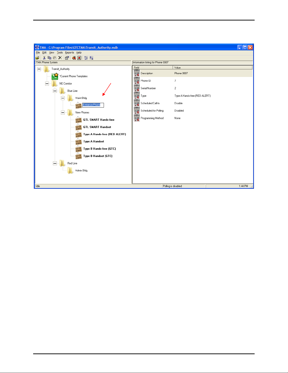
To rename the phone (or any phone), select and click on the phone name and type the new name in the
box, as shown below.
The name assigned to the phone record is listed in the Description Field of the “General” section of the
Phone Management Form. Refer to page 24.
e:\standard ioms - current release\42004 instr. man uals\42004-479b.doc
03/14
Page 18

Pub. 42004-479B
Telephone Management Application (TMA) User Guide Page 15 of 128
Auto-Disco very
Auto-Discovery provides an alternate method of adding telephone records (RED ALERT
®
or -005
SMART Handset) to TMA. This method provides the ability for a single installer to connect a telephone
at its installed location and have TMA automatically create a phone record for it. In addition, TMA
synchronizes the new phone record with the installed telephone. After synchronization completes, the
installer can then test the telephone to confirm its operation. This Auto-Discovery feature avoids the need
to have a second person helping at the TMA PC while installing additional telephones in the system.
Through Auto-Discovery, the new telephone calls the TMA PC. TMA then creates a new phone record in
the database by copying from the “Template” phone for that phone type. Next, TMA makes a poll call to
the telephone to synchronize the settings in the telephone to the new phone record. When this poll call
completes, the auto-dial memory numbers and the configuration settings of the installed telephone will
match those of the new phone record in the database.
OTE: Auto-Discovery can be used only with RED ALERT
N
®
and -005 series SMART handset
telephones. It is not applicable to VoIP/WiFi telephones.
The new phone record will be located in the New Phones group; the description is set to be the record
creation date and time and the phone number.
Initial Checks
To use Auto-Discovery:
1. Confirm that TMA is not currently polling any telephones.
2. Confirm that each telephone being added will be connected to a dedicated line from the PABX.
3. Note the line number (PABX extension) and location of each telephone being added.
Review completely the following steps to use Auto-Discovery. Print these pages and fill-in the
telephone line numbers required in steps 7 and 8 using the right-hand column. This allows for key
in of these settings quickly enough so that the Type A telephone recognizes and acknowledges the
keypad entries. The right column shows the installer key press actions and shows the expected
phone response in [brackets].
e:\standard ioms - current release\42004 instr. man uals\42004-479b.doc
03/14
Page 19
Pub. 42004-479B
Telephone Management Application (TMA) User Guide Page 16 of 128
Complete the following procedure at the telephone site location. Print the form in Table 3 below.
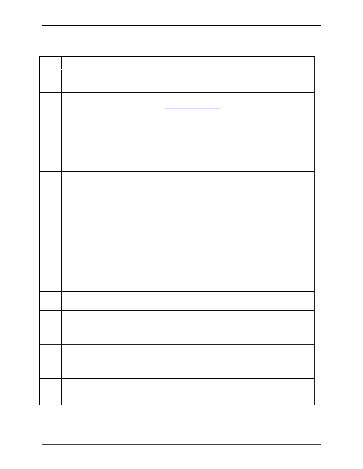
Table 3. Auto-Discovery Procedure
Step Explanation of St ep Actions Installer Actio ns
1 Connect the phone line to the Type A telephone at its site
location. Wait 30 seconds.
2 The following steps use “local” access programming (keypad required). Refer to GAI-
Tronics Pub. 42004-438 (available on www.gai-tronics.com
Type A telephones that do not include an integral keypad will require the use of a No.
51035-011 Keypad and No. 61504-048 Keypad Cable Assembly. The keypad and cable
must be connected to J13 on the PCBA.
The CALL push-button connector J1 is exclusively used for local programming. Type A
telephones that include only the EMERGENCY push button must temporarily have the
associated switch harness plug moved from the EMERGENCY connector J7 to the CALL
push-button connector J1 on the PCBA.
3 Press the CALL or EMERGENCY push button (whichever is
connected to J1).
When the dial tone is heard from the speaker,
simultaneously press the “1” and “#” keypad buttons.
If the telephone is in its factory-programmed Standard
Mode, the telephone generates a splash tone
(low to high sequence), followed by a success tone
(short beep).
Connect Tip/Ring.
Wait 30 sec.
) for further instructions.
Press J1 button, then 1 + #
[ tone(s) ]
If the telephone has previously been used with TMA, it
generates only a success tone (short beep).
4 Immediately after the success tone, use the keypad and
press
*** to enter Programming Mode.
5 Wait 2 seconds. Wait 2 sec.
6 Using the telephone’s keypad enter **0000 to gain access
with the factory-default password.
7 Next, enter *127 followed by the phone number of the
telephone. When finished, press #. The telephone outputs
a success tone (from the speaker of hands-free phones, or
the earpiece at handset phones) to acknowledge the entry.
8 After the success tone, enter *123 followed by the
telephone number assigned to the TMA DTMF
Transceiver. When finished, press #. The phone outputs a
success tone to acknowledge the entry.
9 After the confirmation tone, enter *99 to end the set up.
The telephone outputs a success tone to confirm
completion of the entry.
* * * [no tone]
* * 0 0 0 0 [no tone]
_ _ _ _ _ _ #
*1 2 7
[ one tone]
_ _ _ _ _ _ #
*1 2 3
[ one tone]
*9 9
[ one tone]
e:\standard ioms - current release\42004 instr. man uals\42004-479b.doc
03/14
Page 20

Pub. 42004-479B
Telephone Management Application (TMA) User Guide Page 17 of 128
Step Explanation of St ep Actions Installer Actio ns
10 A few seconds after the success tone of the previous step,
the telephone initiates a Call-In to the TMA PC.
The duration is typically 1 to 2 minutes, but could be up to
5 minutes. Approximately 1 minute after the Call-In
begins, two short tone bursts are output from the speaker (if
it is a hands-free model).
11 Within 40 seconds after the Call-In completion, the TMA
PC initiates a poll call to the Type A telephone. In this poll
call, TMA updates the telephone’s settings based on the
parameters contained in the original template phone.
OTE: During the poll call of a hands-free phone, two
N
short tone bursts are output from the speaker approximately
5 minutes into the poll call.
12 Wait 30 seconds after hearing these two short tone bursts
for the poll call to complete.
13 Return the EMERGENCY push-button switch harness plug
EMERGENCY connector J7 (if it was moved in Step
to the
2). Make several test calls from the telephone to confirm
proper operation.
At the TMA PC Location
Wait 1-2 minutes.
[ two tones]
Wait 2 minutes.
Wait 6 minutes.
[ two tones]
Wait 30 sec
Reconnect the EMERGENCY
button. Test the telephone.
At the TMA PC, use the line number /location list to rename each new phone record as appropriate. (The
new phone records created are located in the “New Phones” group; the description was set as the creation
date and time and the PABX extension number.)
Make note of any unused or redundant phone records for later deletion.
e:\standard ioms - current release\42004 instr. man uals\42004-479b.doc
03/14
Page 21
Pub. 42004-479B
Telephone Management Application (TMA) User Guide Page 18 of 128
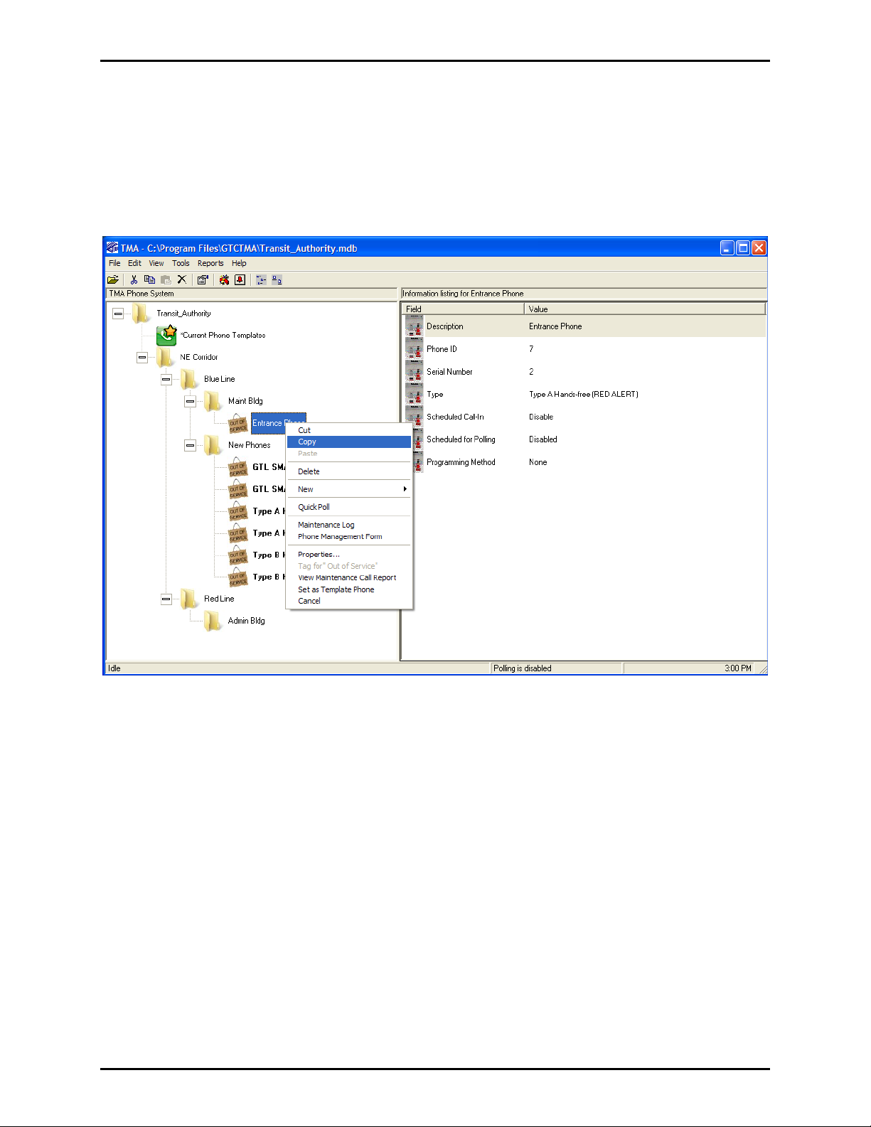
Copying a Phone Recor d
If a phone record already exists with a configuration similar to an existing phone, the existing phone
record can be copied to create a new phone record.
To copy an existing phone record, highlight the phone to be copied, right click and select
Copy from the
pop-up menu, as shown below page. In this example, the “Entrance Phone” at the “Maint Bldg” will
copied into the “Maint Bldg.”
e:\standard ioms - current release\42004 instr. man uals\42004-479b.doc
03/14
Page 22
Pub. 42004-479B
Telephone Management Application (TMA) User Guide Page 19 of 128
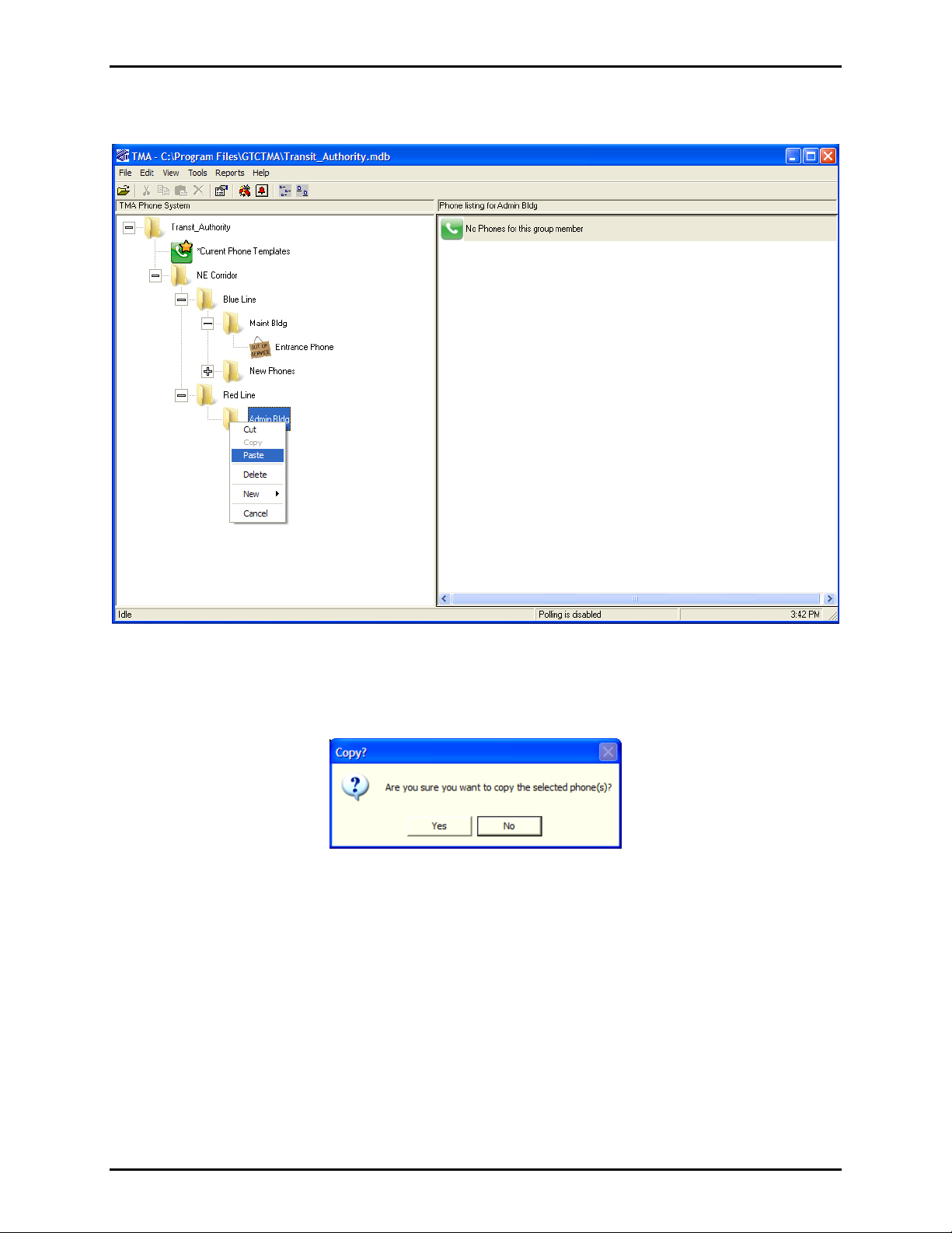
Next, select and right click on the group level which will hold the new phone record, as shown below.
Paste in the pop-up menu.
Select
The following window will open asking, “Are you sure you want to copy the selected phone(s)? Click
Yes to continue.
e:\standard ioms - current release\42004 instr. man uals\42004-479b.doc
03/14
Page 23
Pub. 42004-479B
Telephone Management Application (TMA) User Guide Page 20 of 128
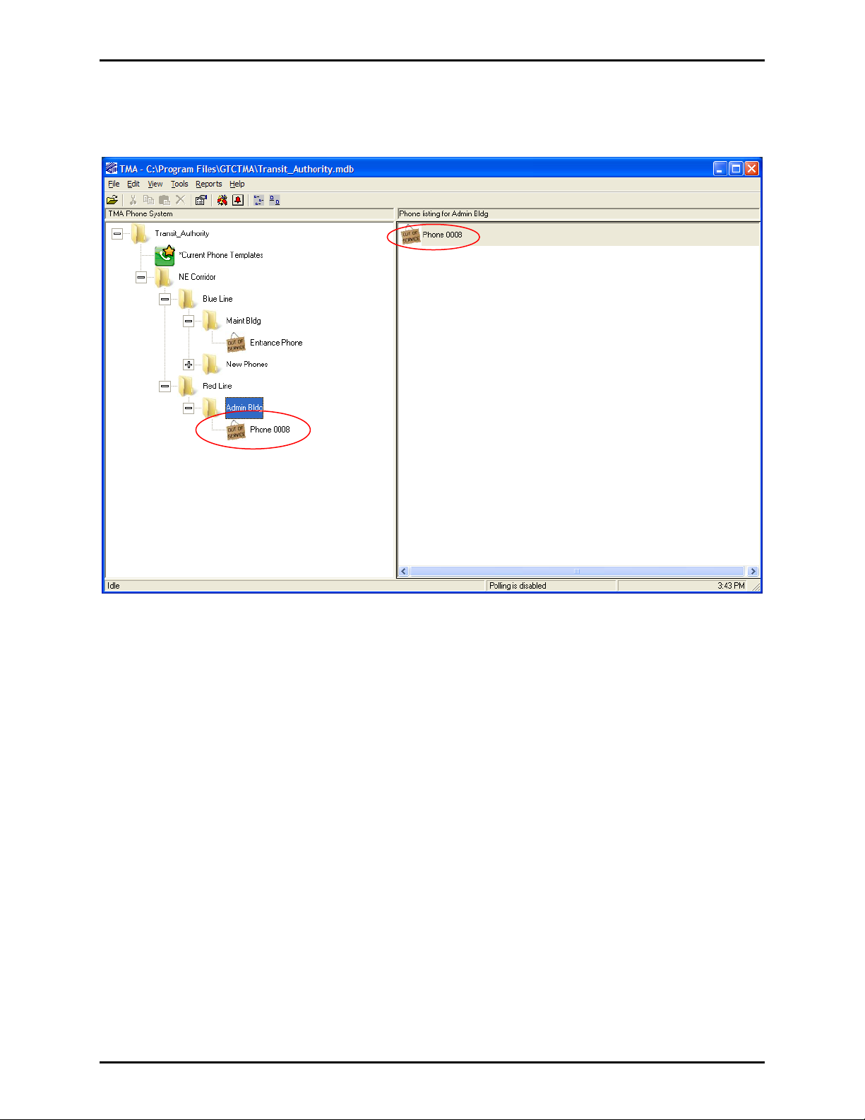
The new (or copied) phone record is added to the database and is assigned the next sequence number, in
this case, Phone 0008, which appears in the “TMA Phone System” tree (under the “Admin Bldg”) and in
the “Phone Listing” (to the right), as shown below.
e:\standard ioms - current release\42004 instr. man uals\42004-479b.doc
03/14
Page 24
Pub. 42004-479B
Telephone Management Application (TMA) User Guide Page 21 of 128
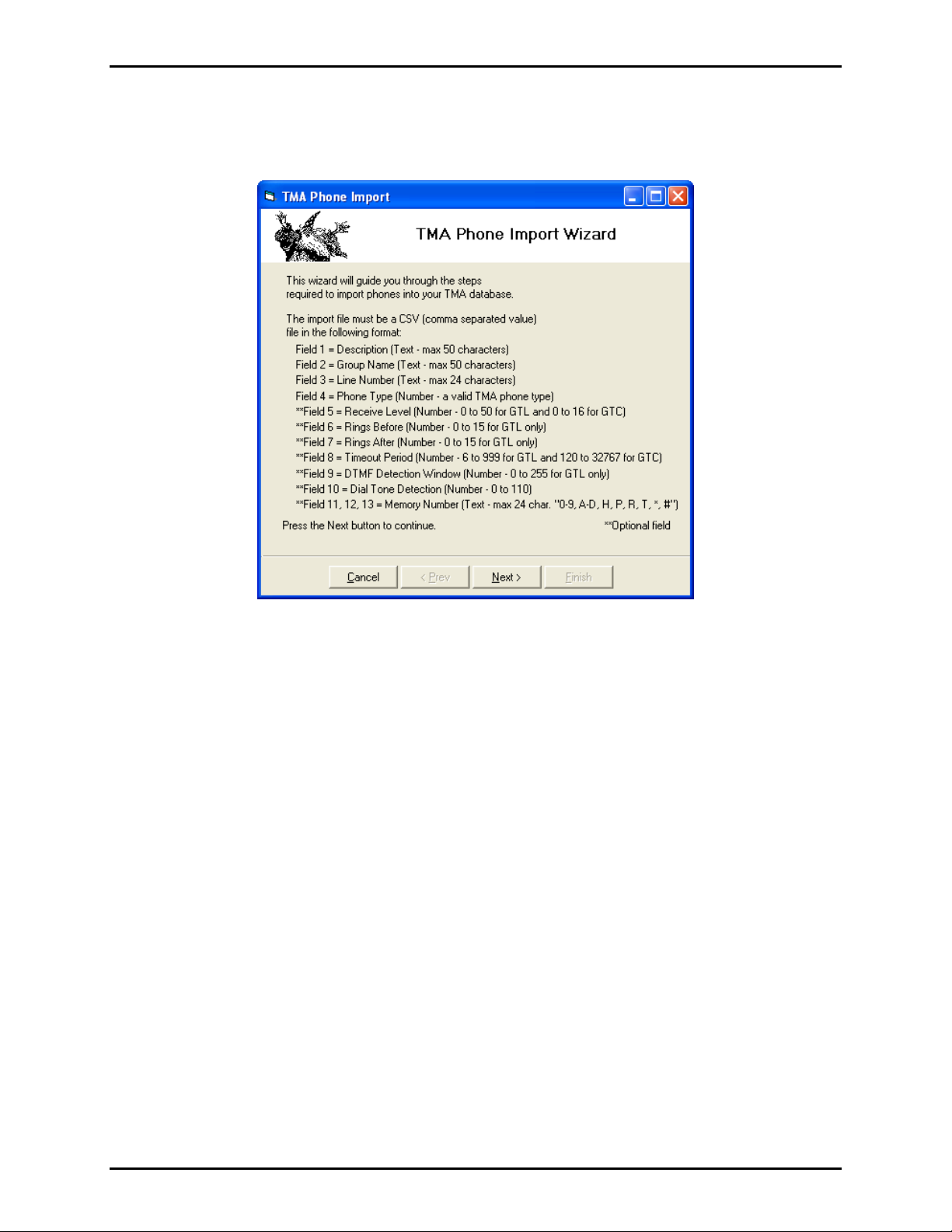
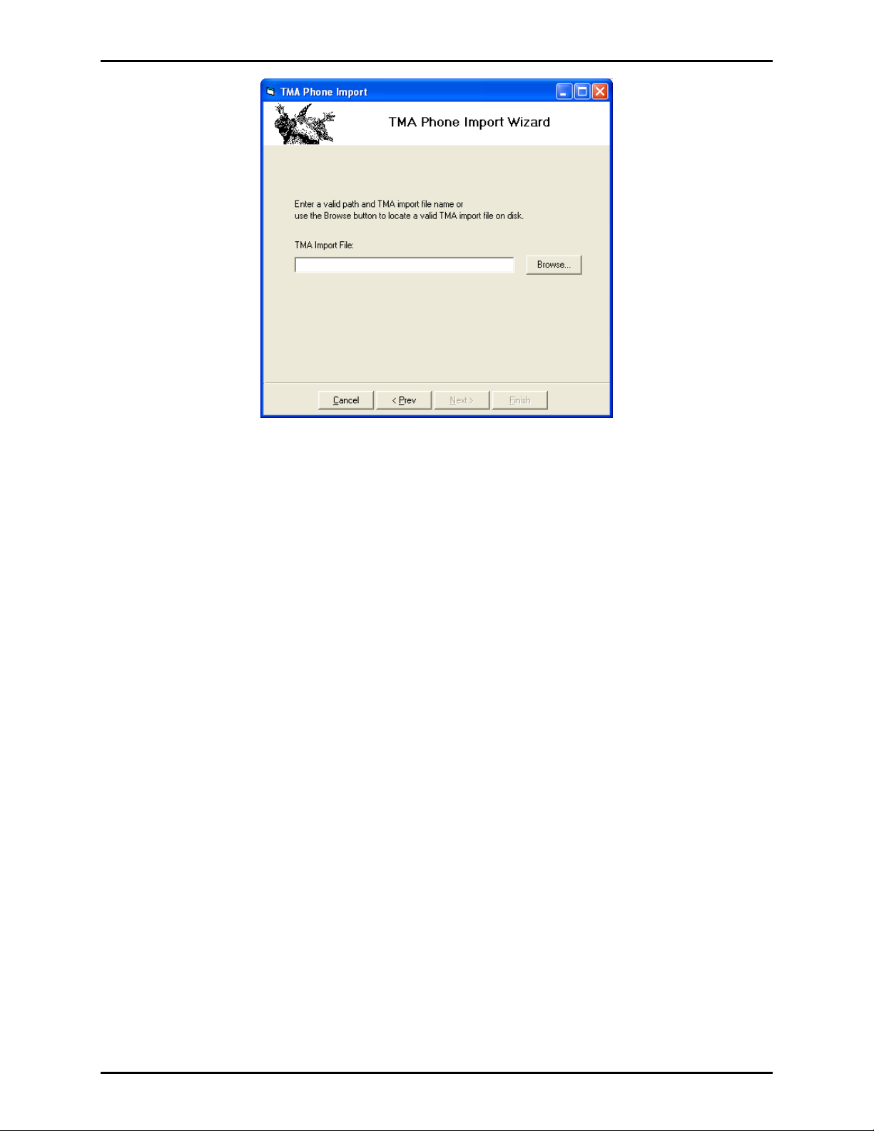
Import
Phone records can be added to the database by importing from a Comma Separated Value (CSV) file.
Include fields in this text file as shown on the opening form of the TMA Phone Import Wizard.
Fields 1–4 are required and are described as follows:
Field 1: “Description” as shown in Table 5.
Field 2: The name of an existing group (folder) at level 3 in the site’s phone record tree structure.
Field 3: “Line Number” as shown in Table 5. (N
OTE: This field is the same as IP Address for VoIP
phones.)
Field 4: “Phone Type Number” as a code number corresponding to the telephone type. Refer to Table 2
and the following list:
Use 8 for GAI-Tronics VoIP Phones
Use 6 for Type A or Type B Hands-free
Use 5 for Type A or Type B Handset
Use 2 for GTL Hands-free
Use 1 for GTL Handset
For the Type A and Type B telephones, TMA will assume the proper phone record type (and icon) after
the telephone has completed its first poll call. Refer to “Phone Management Form” section for details
pertaining to the remaining optional fields.
Next > to continue to the File Selection Form.
Click
e:\standard ioms - current release\42004 instr. man uals\42004-479b.doc
03/14
Page 25
Pub. 42004-479B
Telephone Management Application (TMA) User Guide Page 22 of 128
Type the CSV file name including the full path (or select it using the Bro wse button). Click Finish to
create new phone records in the database according to the specified CSV file.
e:\standard ioms - current release\42004 instr. man uals\42004-479b.doc
03/14
Page 26
Pub. 42004-479B
Telephone Management Application (TMA) User Guide Page 23 of 128
Managing Phone Reco rds
With groups established and named for the telephone system, individual telephone settings can be
modified through the Phone Management Form; with the exception of the VoIP phones (refer to “VoIP
Phone Properties Form” section on page 52).
Phone Management F orm
The Phone Management Form is used to set up synchronization of settings (data) between TMA and the
SMART telephones. Synchronization can be accomplished by:
Sending data to a telephone (synchronize the data in a phone to the data in TMA)
Receiving data from a telephone (synchronize the data in TMA to the data in a phone)
A combination of send data and receive data
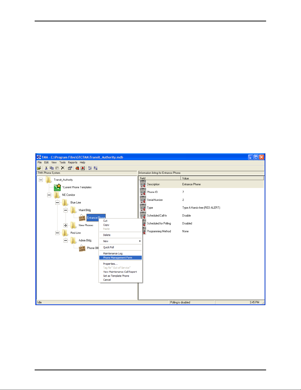
To access the Phone Management form, right click on the phone to be configured. When the pop-up
menu appears (as shown below), move the cursor and click on Phone Management Form. In this
example, the selected phone record to be configured is the “Entrance Phone” at the “Maint Bldg.”
e:\standard ioms - current release\42004 instr. man uals\42004-479b.doc
03/14
Page 27
Pub. 42004-479B
y
Telephone Management Application (TMA) User Guide Page 24 of 128
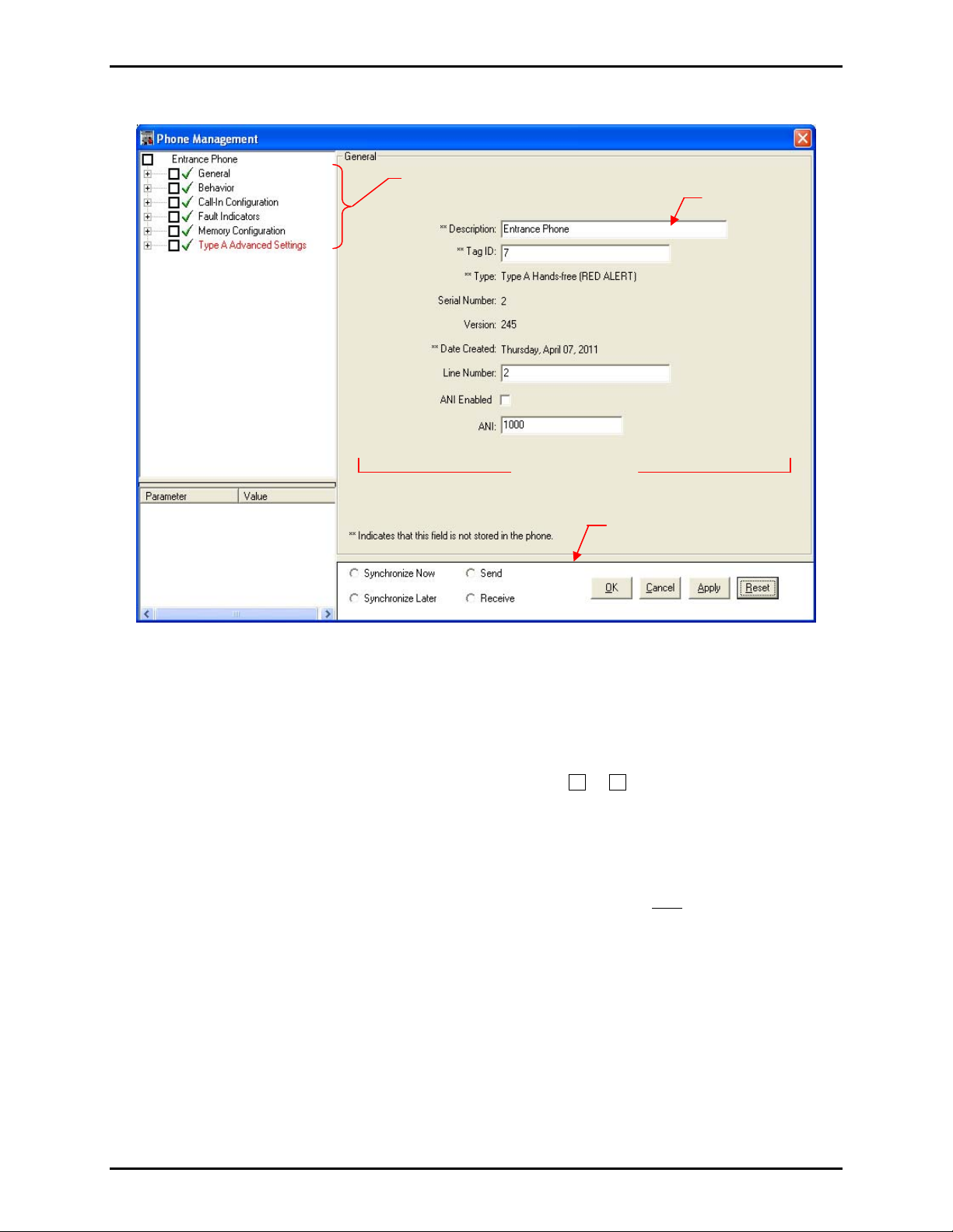
Click on the Phone Management Form to open. It is shown below.
Phone Properties Configuration Forms
Value Field
Phone Properties Area
Phone Data Area
Command Area
nchronization Area
S
The Phone Management Form consists of four areas: Phone Properties, Phone Data, Command Area, and
Synchronization.
Phone Properties Area
The Phone Properties area displays the phone properties in a tree structure. Each property contains
multiple parameters and can be expanded or collapsed by clicking or respectively.
+
־
To select all parameters of a property, click the property check box. To select an individual parameter,
click the parameter check box. All selected parameters will be processed based on user actions in the
Command area.
OTE: The “Type A Advanced Settings” appears in the Phone Properties area only if this phone record is
N
Type A.
Phone Data
The Phone Data area contains parameters with value fields that correspond to the parameter and value
columns in the synchronization list. As each parameter is selected in the Phone Properties Tree, the
appropriate form is displayed in the Phone Data area for entering information in the value fields.
e:\standard ioms - current release\42004 instr. man uals\42004-479b.doc
03/14
Page 28
Pub. 42004-479B
Telephone Management Application (TMA) User Guide Page 25 of 128
Command Area
The Command area is used to queue send/receive requests and to schedule synchronizations for
processing. The user can also reset (undo) changes or cancel the entire operation. The Command area
controls the following actions:
Table 4. Command Area Actions
Command Function
Synchronize
When selected, TMA will immediately poll and synchronize the telephone.
Now
Synchronize
Later
Send
Receive
OK
When selected, data between TMA and the telephone will be synchronized the next
time the telephone is contacted.
When selected, data in the telephone will be synchronized to data stored in TMA.
When selected, data in TMA will be synchronized to data stored in telephone.
When clicked, TMA processes the current synchronization list with the selected
schedule (Now or Later) and closes the Phone Management Form.
Cancel
Apply
When clicked, the Phone Management Form closes and no processing will occur.
When clicked, the selected batch is added to the synchronization list with the current
Send/Receive selection.
Reset
When clicked, it will reset (undo) all changes made after the last “Apply” function.
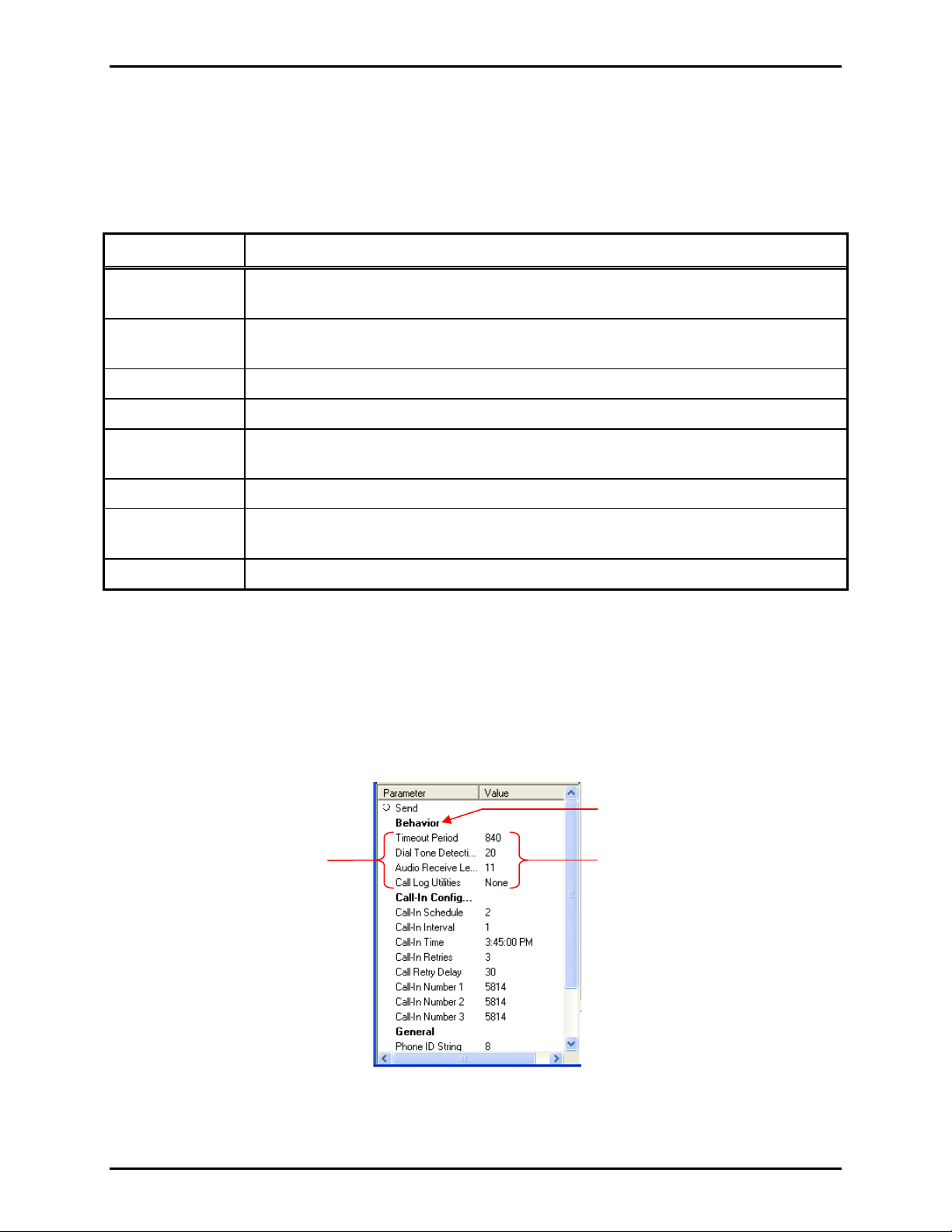
Synchronization Area
The Synchronization area displays a listing of all data selected for processing. The list contains two
columns, Parameter and Value, that correspond to the selections and entries made in the Phone Data area.
Data to be exchanged between the PC and the phone is separated into “Receive” and “Send” batches. The
Parameter column lists the phone property name and the parameters selected. The Value column lists the
entries from the Value fields for each parameter.
Parameters
e:\standard ioms - current release\42004 instr. man uals\42004-479b.doc
03/14
Phone Property
Value Field Entries
Page 29

Pub. 42004-479B
Telephone Management Application (TMA) User Guide Page 26 of 128
Example --Typical Phone Record Setup
In many cases, updating just the Description, Line Number, and Emergency autodial numbers in the GAITronics SMART telephone is sufficient for initial setup. Follow these steps to update a phone record and
to synchronize the telephone to the updated phone record.
1. Choose the type of phone record that corresponds to the telephone model.
2. Right click on the icon of this telephone’s phone record.
3. Click on
4. Click in the
5. Click in the
Phone Management Form.
Description field (General properties) and enter a location/identification description.
Line Number field (General properties) and enter the telephone’s line number exactly as
the TMA DTMF Transceiver or modem will dial it.
6. Click on the title
Memory Configuration in the Phone Properties tree to display the section
containing the autodial telephone numbers.
7. Click in the first
EMERGENCY button is pressed.
8. Click in the second
Emergency field and enter a telephone number that the telephone will dial when the
Emergency field. TMA fills the second and third autodial numbers. Update
these second and third cascade numbers if desired.
9. Select
10. Click
11. Click
Send and Synchronize Now in the Command Area.
Apply (Command Area). This adds all updated values to the Synchronization Area.
OK (Command Area). This closes the Phone Management Form and sends a request to SPI
(SMART Phone Interface) to call the telephone and synchronize it to the updated phone record
settings (i.e., “Send” these values to the telephone).
12. Within 15 seconds, SPI takes the transceiver or modem off-hook and begins the call. As a result of
this maintenance call, the telephone’s health status shown by TMA will also be updated.
13. If desired, monitor the progress of this maintenance call using the SPI call status window. If the SPI
call status window is not open; double-click the telephone icon in the Windows taskbar notification
area to open the call status window.
e:\standard ioms - current release\42004 instr. man uals\42004-479b.doc
03/14
Page 30
Pub. 42004-479B
Telephone Management Application (TMA) User Guide Page 27 of 128
Phone Properties Area
This section examines the parameters of each phone property displayed in the Phone Properties area of
the Phone Management Form.
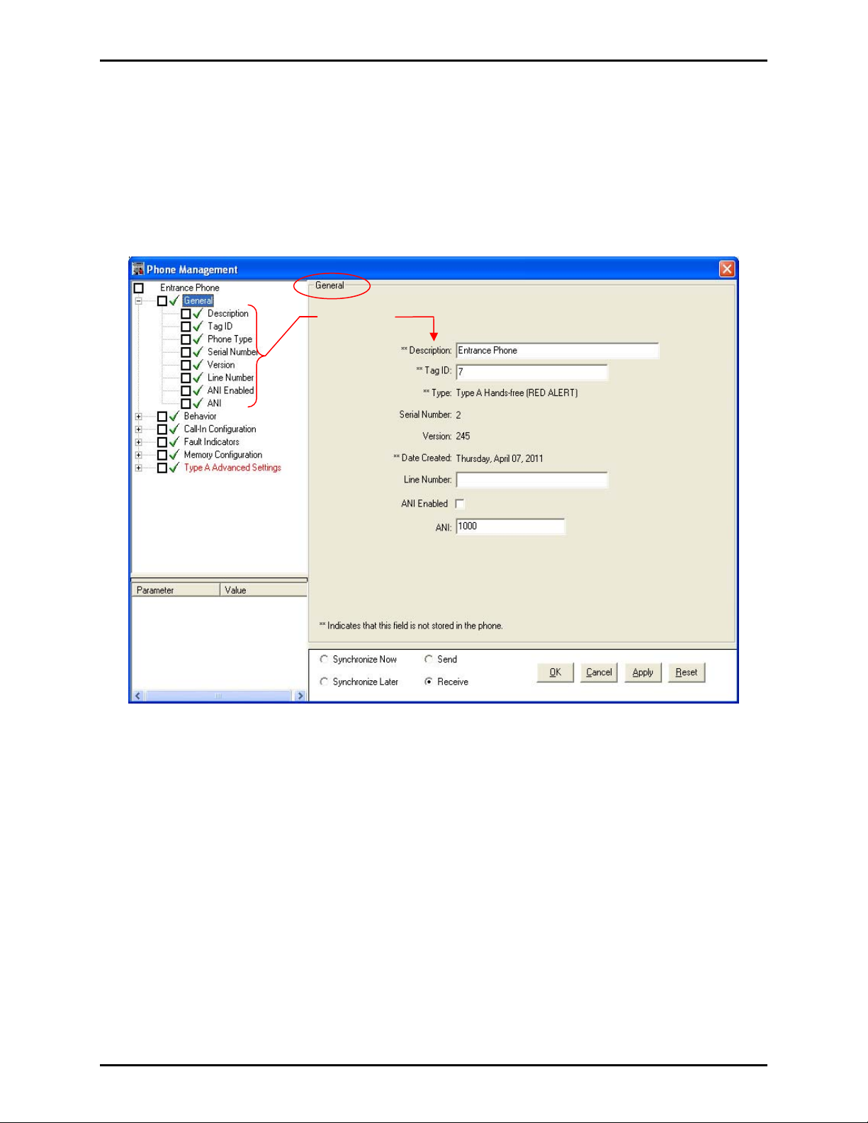
General
The General Properties Form for a Type A Hands-free phone record is shown below followed by an
explanation of each parameter.
Parameters
e:\standard ioms - current release\42004 instr. man uals\42004-479b.doc
03/14
Page 31

Pub. 42004-479B
Telephone Management Application (TMA) User Guide Page 28 of 128
Table 5. General Property Parameters and Their Functions
Parameter Function
** Description
Tag ID
** Type
Serial Number
Version
** Date Created
Line Number
ANI Enabled*
Description is name entered (or assigned) to the telephone in the phone tree list
that will appear on TMA screens and reports.
Tag ID is the site identification label for the telephone. The field is limited to 24
alphanumeric characters and should be unique and easily recognized. This ID
appears on TMA reports, but is not stored in the telephone memory.
Type specifies the type of telephone installed and determines the telephone
settings. This property is set by the profile selected in the Phone Wizard and is
stored only in the TMA database.
A Serial Number is programmed into every telephone during manufacture and is
read by TMA. This field is an important identifier during polling, and cannot be
changed.
Version identifies the firmware installed in the telephone at the time of
manufacture and cannot be changed.
Date Created line identifies when the phone record was added to the TMA
database and cannot be changed.
Line Number is the PABX extension assigned to telephone, which TMA will dial
to send and receive data. The number must be entered exactly as it will be dialed
by the PABX, including any prefixes or area codes.
When checked, the telephone will transmit the ANI code using DTMF when the
called party requests it at the beginning of a call. The called party requests the
ANI transmission by keying the digits 00 (factory default setting), or if
configured, by the digit * or the digit #. Refer to “Voice Annunciation
Activation” on the Properties Form.
ANI*
ANI is a four-digit code that serves as a unit ID when the telephone is set up to
provide unit location transmission on a voice call. Use of ANI is optional. Refer
to “Voice Annunciation Activation” on the Properties Form.
OTE: A DTMF receiver/decoder is required to process the received DTMF ANI code.
*N
e:\standard ioms - current release\42004 instr. man uals\42004-479b.doc
03/14
Page 32

Pub. 42004-479B
Telephone Management Application (TMA) User Guide Page 29 of 128
Behavior
The Behavior Properties Form for a Type A Hands-free phone record is shown below followed by an
explanation of each parameter.
Table 6. Behavior Parameters and Functions
Parameter Function
Timeout Limit
(hh:mm:ss)
The Timeout Limit sets the duration of a user call at the telephone. At the end of
the timeout period, the telephone automatically terminates the call.
This parameter displays two fields with entries made only in the first (number)
field. Entries in the number field are in 0.5-second increments. The second field
displaying “hh:mm:ss” cannot be changed.
Example: A numerical value of 1200 = 10 minutes (as shown above). The
minimum call duration is 1 minute (a numerical value of 120). The maximum
duration is 04:33:04.
Primary Dial Tone
Delay
Secondary Dial
Tone Delay
Primary Dial Tone Delay controls the time limit the telephone uses to detect dial
tone. The recommended setting is 3–5 seconds.
OTE: If dial tone is not detected within the specified time, dialing will proceed.
N
Secondary Dial Tone Delay controls the time limit the telephone uses to detect dial
tone after a digit is entered to access an outside line. The recommended setting is
2–4 seconds.
OTE: If dial tone is not detected within the specified time, dialing will proceed.
N
e:\standard ioms - current release\42004 instr. man uals\42004-479b.doc
03/14
Page 33

Pub. 42004-479B
Telephone Management Application (TMA) User Guide Page 30 of 128
Parameter Function
Audio Receive
Level
Initial Handset
Volume
Call log Utilities
DTMF ##
Disconnect
For Type-B Hands-free telephones, sets the limit of the speaker audio power. (This
is particularly important if the telephone line current is below 30 mA.) This setting
is used to compensate for abnormal line input level. If it is set too high, speaker
output power can exceed available line power, and the call can disconnect
unexpectedly. For a telephone with a cone speaker, the setting is 11 for normal
line audio levels. If the line audio level is low, increase this setting by small steps
to provide for a higher speaker volume.
For a telephone with a non-metallic speaker assembly, use 15 for optimum
performance.
For a Type-A handset telephone, the VOLUME push button on the front panel
allows the user to select any of five preset volume levels. This setting determines
which of the five available handset volume levels the telephone uses at the start of
the call.
The Call log Utilities consists of three selections to obtain, clear (delete) or ignore
call logs stored in the telephone’s memory. Each is explained below:
Get Call Log – directs TMA to obtain the call log stored in the telephone.
Clear Call Log – directs the telephone to clear the call log entries stored in
memory.
None – no actions are taken with the call log stored in the telephone memory.
When checked, entry of the DTMF “#” digit two times by the connected party will
terminate the call.
Voice Trigger
LED
Dial Tone
Disconnect
Auto Answer
Alert
Open Gate
Command
Gate Latch
Duration
Extended Strobe
Enabled
Emergency
Disconnect
Lockout
When checked, the Call Received LED illuminates in a steady state when the
telephone detects audio on the line other than dial tone, DTMF tones or a busy
tone.
When checked, the telephone disconnects from the line if dial tone is detected
during a user call.
When checked, the telephone will output a brief alert tone to indicate it has been
accessed and is active on the line for a user call.
This is the security access code to activate dry contact output 4 to open a gate or
door latch. The security code field will accept a maximum of eight numeric digits
(0–9). The first digit cannot
be zero.
This sets the length of time output 4 is active when a successful Open Gate
Command is received.
When checked, the strobe connected to the telephone remains active for a preset
interval after the user call ends. This duration is set in the “Extended Strobe
Duration” field directly below the check box. This feature requires the use of an
external power supply.
This sets the length of time the E
MERGENCY button is locked out (prevented) from
terminating a user call (if depressed a second time), after a call is initiated.
e:\standard ioms - current release\42004 instr. man uals\42004-479b.doc
03/14
Page 34

Pub. 42004-479B
Telephone Management Application (TMA) User Guide Page 31 of 128
Parameter Function
Voice
Annunciation
Activation
Ringing (Manual
Answer)
Blind Autodial +
Early Mic
Emergency Button
Disconnect
A telephone can be equipped with an optional Voice Annunciation module, which
can have one stored message for play back. To activate a message play back from
the voice module, the caller keys the digits 00 (factory default setting). If the
“Pound [#]” or “Star [*]” check boxes are checked, then either 00 or # or *
activates the voice play back. These selections also apply to ANI transmission.
Refer also to “ANI” and “ANI Enabled” on the General Properties Form. If ANI is
enabled and the Voice Annunciation module is installed, the telephone plays the
voice announcement and then transmits the ANI.
When checked, an incoming call at the telephone causes a ringing tone at the
telephone’s speaker (if hands-free) or sounder (if equipped with a handset), and the
call can be answered by a user for voice communication.
When checked, the phone’s microphone becomes active immediately after the
telephone dials an outgoing user call. Use this setting with caution since audio
detected by the telephone’s microphone can cause the Call Received LED to
illuminate, and give the user (caller) a false indication that the called party has
answered the call.
When checked, a second depression of the E
MERGENCY button at the phone will
terminate the call, only after the time set in the Emergency Disconnect Lockout
field has elapsed.
e:\standard ioms - current release\42004 instr. man uals\42004-479b.doc
03/14
Page 35

Pub. 42004-479B
Telephone Management Application (TMA) User Guide Page 32 of 128
Call-In Configuration
The Call-In Properties Form for a Type A Hands-free phone record is shown below followed by an
explanation of each parameter.
Table 7. Call-In Properties Parameters and Their Functions
Parameter Function
Call-In Schedule
The Call-In Schedule determines the frequency at which the telephone is to call
TMA to provide an update. This field has four entries, which are:
Disable – disables the call-in feature.
Daily – directs the telephone to call in on a daily basis at the time set in the “Call-In
Time” field.
Every n hours – directs the telephone to call-in every “n” hours based on the
number selected in the “Call-In Interval” field.
Out of Service – sets a flag for TMA that the telephone is currently “out of service.”
This setting prevents TMA from polling the telephone.
Call-In Interval
The Call-In Interval sets the number of times the call-in process will occur with “n”
representing the number of hours between call-ins.
Example: If the telephone is configured for Every n hours in the Call-In Schedule
and this field is set to “2,” the telephone will call in every 2-hours.
OTE: Telephones configured to call in Daily in the Call-In Schedule will ignore
N
this interval and will call in only at the time specified in the Call-In Time field.
e:\standard ioms - current release\42004 instr. man uals\42004-479b.doc
03/14
Page 36

Pub. 42004-479B
Telephone Management Application (TMA) User Guide Page 33 of 128
Parameter Function
Call-In Time
The Call-In Time sets the time of day the telephone will call in, and can be set in 1minute increments.
Type B telephones only: During a scheduled call-in, the telephone updates TMA
with the next scheduled call-in time. In the event a telephone does not complete a
scheduled call-in, the telephone defaults to performing to a daily call-in mode.
Number of CallIn Retries
The Number of Call-In Retries directs the telephone to make additional call-in
attempts (or retries) if the first attempt was unsuccessful. Each additional call-in
attempt occurs at 50-second intervals and is not
determined by the Call-In Retry
Delay below.
Call-In Number
The Call-In Number has a group of three fields. The first number is the primary
number the telephone will dial at scheduled (or unscheduled) call-in times.
If the primary call is unsuccessful, the telephone cascades to the second number in an
attempt to complete the maintenance call. If the second number is also unsuccessful,
the third number will be attempted.
Fault Indicators
A telephone can report status for several inputs, which can be internal or external to the telephone. The
function of an input can be assigned a “Common Name” via drop-down list selections, which will appear
on reports. A “Fail” (fault) condition is reported for a stuck (closed) contact. The “Fault Indicators”
properties form is shown below followed by explanations of the available selections.
Fault Indicator Numbers
e:\standard ioms - current release\42004 instr. man uals\42004-479b.doc
03/14
Page 37

Pub. 42004-479B
Telephone Management Application (TMA) User Guide Page 34 of 128
Table 8. Fault Indicators
Parameter Common Name Fu nct ion
AUX1 or INTG
(Fault Indicator 1)
The AUX1 or INTG (Auxiliary 1 or Integrity) fault input allows reporting of
various “named” sensory devices, if connected to this input at the phone.
The following selections are available in the “Common Name” field:
Not Used – when selected, a fault detected at the input is not reported.
Aux 1 – when selected, this input is listed with the generic “Aux1” label.
Autodial 3 – is used if a momentary input is used to start a call that uses the “Bank
3” Autodial memory numbers. A failure condition indicates a stuck switch contact.
Hookswitch – enables reporting of an off-hook condition from the hookswitch
only at phones equipped with a handset.
Handset Integrity – enables reporting of a break in the handset cord at phones
equipped with a handset.
Manual Trigger – is used if a manual switch is connected to the input.
Door – enables reporting of an open door via a door switch sensor, if installed at a
weatherproof phone or a stanchion with door access.
Tilt – enables reporting of a tilted (or leaning) condition of a phone or stanchion, if
a tilt switch sensor is installed.
Strob Const Lamp (Strobe Constant-On Lamp) – is used if the input is
connected to a strobe status contact to indicate failure of the Constant-On Lamp.
Solar Panel Wiring – is used if the input is connected to a solar panel wiring fault
contact.
Stanchion Battery – is used if the input is connected to a stanchion battery fault
contact.
AUX2
(Fault Indicator 2)
The AUX2 (Auxiliary 2) fault input allows reporting of various “named” sensory
devices, if connected to this input at the telephone. The following selections are
available in the “Common Name” field:
Not Used – when selected, a fault detected at the input is not reported.
Aux 2 – when selected, this input is listed with the generic “Aux 2” label.
Call Button – is used if the input connects to the Call button. A failure condition
indicates a stuck switch contact.
Autodial 4 – is used if a momentary input is used to start a call that uses the “Bank
4” Autodial memory numbers. A failure condition indicates a stuck switch contact.
Hookswitch – enables reporting of an off-hook condition from the hookswitch
only at phones equipped with a handset.
Manual Trigger – is used if a manual switch is connected to the input.
Door – enables reporting of an open door via a door switch sensor, if installed at a
weatherproof phone or a stanchion with door access.
Tilt – enables reporting of a tilted (or leaning) condition of a phone or stanchion, if
a tilt switch sensor is installed.
Strob Const Lamp (Strobe Constant-On Lamp) – is used if the input is
connected to a strobe status contact to indicate failure of the constant-on lamp.
Solar Panel Wiring – is used if the input is connected to a solar panel wiring fault
contact.
Stanchion Battery – is used if the input is connected to a stanchion battery fault
contact.
e:\standard ioms - current release\42004 instr. man uals\42004-479b.doc
03/14
Page 38

Pub. 42004-479B
Telephone Management Application (TMA) User Guide Page 35 of 128
Parameter Common Name Fu nct ion
EMERG
PUSHBUTTON
(Fault Indicator 3)
CALL
PUSHBUTTON
(Fault Indicator 4)
N/A
(Fault Indicator 5)
The EMERG PB (E
MERGENCY push button on the front of the telephone, or other “named” sensory
E
MERGENCY push button) fault input allows reporting of the
devices at the telephone. The following selections are available in the “Common
Name” field:
Not Used – when selected, a fault detected at the input is not reported.
Emergency Button – is used if the input connects to the E
MERGENCY button. A
failure condition indicates a stuck switch contact.
Autodial 1 – is used if a momentary input is used to start a call that uses the “Bank
1” Autodial memory numbers. A failure condition indicates a stuck switch contact.
Manual Trigger – is used if a manual switch is connected to the input.
The CALL PB (C
ALL push button) input allows reporting of the CALL push button
on the front of the telephone, or other “named” sensory devices at the telephone.
The following selections are available in the “Common Name” field:
Not Used – when selected, a fault detected at the input is not reported.
Call Button – is used if the input connects to the C
ALL button. A failure condition
indicates a stuck switch contact.
Autodial 2 – is used if a momentary input is used to start a call that uses the “Bank
2” Autodial memory numbers. A failure condition indicates a stuck switch contact.
Manual Trigger – is used if a manual switch is connected to the input.
The N/A (not applicable) fault input is dedicated to the telephone’s memory, and
only the following two selections are available in the “Common Name” field:
Not Used – when selected, a fault detected in the telephone’s memory is not
reported.
Memory Abnormal – when selected, a fault detected in the telephone’s memory
will be reported.
HNDST INTG
(Fault Indicator 6)
The Handset Integrity Loop input reports status of a switch connected to clips E1
and E2 on the 69577 PCBA or other “named” sensory devices at the telephone.
The following selections are available in the “Common Name” field:
Not Used – when selected, a fault detected at the input is not reported.
Power Supply – is used if the input is connected to an external power supply fault
contact.
Door – enables reporting of an open door via a door switch sensor, if installed at a
weatherproof phone or a stanchion with door access.
Tilt – enables reporting of a tilted (or leaning) condition of a phone or stanchion, if
a tilt switch sensor is installed.
Strob Const Lamp (Strobe Constant-On Lamp) – is used if the input is
connected to a strobe status contact to indicate failure of the Constant-On Lamp.
Solar Panel Wiring – is used if the input is connected to a Solar Panel Wiring
fault contact.
Stanchion Battery – used if input is connected to a stanchion battery fault contact.
Key A – when selected, this input will be listed by the generic “Key A” label
representing key switch contact “A.”
Handset Integrity – indicates that this input is being used with a handset to
indicate a break in the handset cord.
e:\standard ioms - current release\42004 instr. man uals\42004-479b.doc
03/14
Page 39

Pub. 42004-479B
Telephone Management Application (TMA) User Guide Page 36 of 128
Parameter Common Name Fu nct ion
HNDST
HOOKSW
(Fault Indicator 7)
The HNDST HOOKSW fault input reports status of a switch connected to pins 3
and 4 at J8 (Key switch “C”) or other “named” sensory devices at the telephone.
The following selections are available in the “Common Name” field:
Not Used – when selected, a fault detected at the input is not reported.
Power Supply – is used if the input is connected to an external power supply fault
contact.
Door – enables reporting of an open door via a door switch sensor, if installed at a
weatherproof telephone or a stanchion with door access.
Tilt – enables reporting of a tilted (or leaning) condition of a telephone or
stanchion, if a tilt switch sensor is installed.
Strob Const Lamp (Strobe Constant-On Lamp) – is used if the input is
connected to a strobe status contact to indicate failure of the constant-on lamp.
Solar Panel Wiring – is used if the input is connected to a solar panel wiring fault
contact.
Stanchion Battery – is used if the input is connected to a stanchion battery fault
contact.
Key C – when selected, this input is listed by the generic “Key C” label
representing key switch contact “C.”
Hookswitch – indicates that this input is being used with a handset cradle
hookswitch. A fail status indicates that the handset has not been returned to the
cradle after use. (i.e. left free hanging)
PW ENABLE P2-3
(Fault Indicator 8)
Fault Indicator 9
(Line Interrupt)
The PW JUMPER P2-3 input reports status of a switch connected to pins 2 and 3 at
J9 (Password Enable jumper) or other “named” sensory devices at the telephone.
The following selections are available in the “Common Name” field:
Not Used – when selected, a fault detected at the input is not reported.
Power Supply – is used if the input is connected to an external power supply fault
contact.
Door – enables reporting of an open door via a door switch sensor, if installed at a
weatherproof phone or a stanchion with door access.
Tilt – enables reporting of a tilted (or leaning) condition of a phone or stanchion, if
a tilt switch sensor is installed.
Strob Const Lamp (Strobe Constant-On Lamp) – is used if the input is
connected to a strobe status contact to indicate failure of the constant-on lamp.
Solar Panel Wiring – is used if the input is connected to a solar panel wiring fault
contact.
Stanchion Battery – is used if the input is connected to a stanchion battery fault
contact.
PW Jumper – when selected, this input is listed by the generic “Password
Jumper” label. This is appropriate for most uses with the jumper clip on header J9.
In the event telephone line service is disrupted for 8 or more minutes, the telephone
logs the event and performs a call-in to TMA only if the adjacent “Call-In After
Use” check box is checked. This selection cannot be changed.
e:\standard ioms - current release\42004 instr. man uals\42004-479b.doc
03/14
Page 40

Pub. 42004-479B
Telephone Management Application (TMA) User Guide Page 37 of 128
Parameter Common Name Fu nct ion
Fault Indicator 10
(Microprocessor
Self Test)
Fault Indicator 11
(Call Log 90%
Full)
Fault Indicators
12 through 17
In the event any abnormal processing activity occurs during periodic testing of the
phone’s microprocessor, the phone logs the occurrence and performs a call-in to
TMA, only if the adjacent “Call-In After Use” check box is checked. This
selection cannot be changed.
If (or when) the telephone’s call log memory becomes 90% full, the phone logs the
condition and performs a call-in to TMA after a user call only if the adjacent “CallIn After Use” check box is checked. This selection cannot be changed.
Fault Indicators 12–16 are dedicated to functions listed below, and cannot be
changed:
(12) Last Maintenance Call Interrupted – indicates the most recent poll call or
call-in failed and the phone’s health status was not received by TMA.
(13) Last Call-In Failed – indicates the most recent attempt by the telephone to
call-in to TMA failed and the phone’s health status was not received by TMA.
(14) Stuck Buttons – indicates a push button on the phone is stuck in a closed
position. This also applies to a keypad.
(15) Memory Synchronize – indicates the TMA database does not contain the
same settings as the telephone for one or more of autodial phone numbers.
(16) Configuration Synchronize – indicates the TMA database does not contain
the same settings as the telephone for one or more of its parameter settings other
than the autodial numbers.
(17) Voice Annunciation Option Battery – indicates that the battery in the Voice
Annunciation option require replacement.
Common Name
Enabled
NC Switch
Maint. Call
Voice Call
Call-in After Use
The Common Name drop-down lists are used to identify which telephone fault
indicator is connected to a particular input, for reporting purposes.
OTE: The fault indicator names in the drop-down list may differ from phone to
N
phone depending on how or which fault indicators are being used.
When checked, the fault indicator selected in the “Common Name” is enabled and
will be reported. If unchecked, it is disabled, and any fault information received on
that sensor is not reported.
OTE: If the sensor does not exist in the telephone, the fault indicator should be
N
disabled to avoid “phantom” faults from appearing in exception reports.
When checked, the contact is Normally Closed (N.C.), which is the “normal” state
of a fault indicator contact closure. If unchecked, the contact closure for the sensor
is Normally Open (N.O.).
When selected, the telephone initiates a call-in to the primary number in the call-in
number(s) memory bank.
When selected, the telephone places a voice call when the selected fault indicator
state becomes faulted. The voice call is made from the appropriate memory bank
of autodial numbers, which is determined by the depression of a specific button.
When checked, the telephone initiates a call-in to TMA after a user call and is
dependent upon the nature of the fault. This function is only available for Fault
Indicators 9, 10 and 11.
e:\standard ioms - current release\42004 instr. man uals\42004-479b.doc
03/14
Page 41

Pub. 42004-479B
Telephone Management Application (TMA) User Guide Page 38 of 128
Memory Configuration
The Memory Configuration Properties Form is shown below followed by an explanation of each entry.
Table 9. Memory Configuration Properties and Their Functions
Parameter Function
Emergency: Bank 1
Emergency Bank 1 is the memory bank for the E
MERGENCY button on the front
of the telephone (see note).
Assistance/Call:
Bank 2
Assistance/Call Bank 2 is the memory bank for the second, non-emergency
button labeled as either C
ALL or ASSISTANCE located on the front of the
telephone (see note).
AUX1: Bank 3
AUX1 Bank 3 is the memory bank for the Auxiliary (spare) input 1 on the board
inside the telephone (see note).
AUX2: Bank 4
AUX2 Bank 4 is the memory bank for the Auxiliary (spare) input 2 on the board
inside the telephone (see note).
Retry Delay
(seconds)
Retry Delay sets the time delay between additional call attempts by a telephone
only when an E
MERGENCY (or HELP) push button is depressed on the front of
the telephone. This delay is usually set to the minimum time period required by
the PABX to reset after previous call attempt.
NOTE: Each memory bank can have up to three numbers. The first number in a memory bank is the
primary auto-dial number. The second and third numbers in each memory bank are cascading auto-dial
numbers. The type of call to be made (call in or voice call) is determined by the configuration of the
phone in the Fault Indicators window.
e:\standard ioms - current release\42004 instr. man uals\42004-479b.doc
03/14
Page 42

Pub. 42004-479B
Telephone Management Application (TMA) User Guide Page 39 of 128
Cascading Autodial Numbers
If an attempt to call the primary number is unsuccessful, the telephone will release that call, and initiate
another call using the second autodial number in that memory bank. If the second call attempt also fails,
the telephone will attempt a third call to the third number stored in that memory bank.
Valid Autodial Numbers
Each memory location will accept up to 24 alphanumeric digits. The valid alphanumeric digits are 0–9,
A, B, C, D,
OTE: Any digits other than 0–9 counts for two character digits of the 24-digit maximum.
N
P (for DTMF #), H for a pause in the dialing sequence, and for the DTMF star (see note).
Type A Advanced Settings
The Type A Advanced Settings Properties Form is shown below followed by an explanation of each
entry.
e:\standard ioms - current release\42004 instr. man uals\42004-479b.doc
03/14
Page 43

Pub. 42004-479B
Telephone Management Application (TMA) User Guide Page 40 of 128
Table 10. Input Switches
Designation Function
Emergency
Call
Aux 1
Aux 2
This is the dry contact switch connected to pins 1 and 2 at J7. This switch is typically
MERGENCY push button.
the E
This is the dry contact switch connected to pins 1 and 2 at J1. This switch is typically
ALL push button.
the C
Can be any dry contact switch connected to the AUX 1 input at TB6.
Can be any dry contact switch connected to the AUX 2 input at TB7.
Table 11. Drop-Down List Selections for Input Switches
Designation Function
Voice Call
TMA
When selected, the input initiates a voice user call.
When selected, the input initiates a call-in to TMA.
Maintenance
Call
Cancel Strobe
Record
Greeting (Mic)
Hook Switch
When selected, the input terminates strobe activity.
When selected, the input activates the record mode of the optional Voice Annunciation
Module.
When selected, the input is designated as the handset cradle hookswitch for on/offhook conditions, unless overridden by another parameter.
Not Used
Not Used
Special 1
Special 2
Special 3
Special 4
The input is not used and is reserved for future use.
The input is not used and is reserved for future use.
The input is reserved for custom applications.
The input is reserved for custom applications.
The input is reserved for custom applications.
The input is reserved for custom applications.
e:\standard ioms - current release\42004 instr. man uals\42004-479b.doc
03/14
Page 44

Pub. 42004-479B
Telephone Management Application (TMA) User Guide Page 41 of 128
Table 12. Fields and Check Boxes for Input Switches
Field/Check B ox Description
Priority
Disable Wake
Allow Disconn.
Emerg.
Autodial Row
This field specifies the priority of the input. The following priorities are generally
assigned:
Priority 1 (highest) – Emergency calls
Priority 2 – (reserved for custom applications)
Priority 3 – Normal voice calls
Priority 4 – Calls that record or play a voice annunciation message
Priority 5 (lowest) – A switch used to start a call-in to TMA.
Check this box to prevent the input from initiating a call.
Check this box to permit an input having equal priority to terminate the call (after
expiration of the Emergency Disconnect Lockout time).
When checked, the call is designated as an “emergency” call and the telephone
activates the strobe output and enables the Disconnect Lockout Interval.
This field directs the phone to a specific memory bank of auto-dial numbers, as
follows:
Enter 0 for Memory Bank 1 (Emergency)
Enter 1 for Memory Bank 2 (Assistance/Call)
Enter 2 for Memory Bank 3
Enter 3 for Memory Bank 4
Enter 4 for Memory Bank 5 (for the call-in autodial numbers)
Speed Dial with
Hook Sw.
When checked, a user must first remove the handset from the cradle, and then
depress a speed dial button.
Designation Function
Out 1
Out 4
CR_LED
CP_LED
Ringer
Ser. Bus (J10:P4)
Output contact 1 at TB2, in the telephone.
Output contact 4 at TB5, in the telephone.
Controls the Call Received LED connected to pins 1 and 2 at J16 in the telephone.
Controls the Call Placed LED connected to pins 1 and 2 at J2 in the telephone.
Controls the piezo ringer connected to pins 3 and 4 at J16 in the telephone.
Controls pin 4 at J10 in the phone. This output is not available for any other
function if an optional Voice Annunciation Module is installed in the telephone.
Table 13. Output Devices
e:\standard ioms - current release\42004 instr. man uals\42004-479b.doc
03/14
Page 45

Pub. 42004-479B
Telephone Management Application (TMA) User Guide Page 42 of 128
Table 14. Drop-Down List Selections Output Devices
Designation Function
No Function
Call Received
Call Placed
Answer Voice Call
Track Ringing
Non-Keypad Voice
Call
Keypad Voice Call
Any Call
Alerter 20 Hz
Warble
Emergency Strobe
LED Flash/Solid
@ Connect
The output is always inactive.
Becomes active when a confirmed call connection occurs.
Becomes active at the start of a voice call and will become inactive when a
confirmed call connection occurs.
Becomes active at the start of a voice call that is being received by the telephone.
Is only active while the telephone is generating a simulated ring-back tone after an
incoming call is received.
Becomes active at the start of a voice call that is not dialed using the keypad.
Becomes active at the start of a voice call that is dialed using the keypad.
Becomes active at the start of any call, whether inbound or outbound.
Provides a pulsed dc signal for the piezo ringer to produce a simulated ringing tone
on an incoming call if the Ringing (Manual Answer) feature is enabled in the
“Behavior” properties.
Becomes active at the start of an Emergency call and is intended to control an
external strobe.
The output pulses at the start of a voice call and then becomes active in a steady
state when a confirmed call connection occurs.
Open Gate
Contact
Mirror Handset
Hookswitch
The output pulses when the phone receives the proper “Open Gate Command” set
in the “Behavior” properties.
The output follows the state of the handset cradle hookswitch.
e:\standard ioms - current release\42004 instr. man uals\42004-479b.doc
03/14
Page 46

Pub. 42004-479B
Telephone Management Application (TMA) User Guide Page 43 of 128
Table 15. Other Fields and Check-Box Selections
Parameter Function
Call Progress
Tone Blocking
Time
CR_LED
Confirmation
Tone
Send DTMF Tone
After Attention
Star Detection
Use Low DTMF
for S/N
Transmit 1st
Autodial # on
Incoming Call
Disable Busy Tone
Counting
When set to a value greater than 100, the telephone will detect North American
Call Progress tones (ring back, busy, fast busy). For other values, this parameter
specifies the time (in seconds) at the start of the call during which the telephone
will ignore these tones, which disables the phone’s ability to redial a call on the
“no answer” or on the “busy” condition. This can be useful when the telephone
system does not meet North American standards.
When checked, the telephone transmits a brief confirmation tone when the Call
Received LED becomes active solid.
When checked, the telephone transmits a brief confirmation tone after it detects the
first “Star” digit of each “Star” command.
When checked, the telephone transmits the serial number prefix using DTMF
numeric digits (0–9) instead of alphabetic digits (A–D). Use of this function is
applicable only
to phones operating behind a cellular interface.
When checked, the telephone transmits the Primary Autodial number for the
MERGENCY push button when it accepts an incoming call. Remote programming
E
is disabled.
SMART Telephones automatically end a call attempt and retry when an auto-dial
or ringdown operation results in several cycles of a Busy or Fast-Busy signal. In
addition, RED ALERT
®
emergency telephones end a keypad call automatically
after detecting six cycles of Busy or Fast-Busy.
Disable Ringback
Counting For
Voice Call
Skip Dial Tone
Detection
When checked, this counting/retry automation is disabled. (This disable option
applies only to telephones having firmware version greater than 301.)
SMART Telephones automatically end a voice call attempt and retry when an
auto-dial call results in many cycles of Ringback signal.
When checked, this counting/retry automation is disabled. (This disable option
applies only to telephones having firmware version greater than 301.)
When checked, the telephone auto-dials its programmed number without waiting to
detect dial tone. Using this option may result in improper dial sequences on some
PABX systems.
(This disable option applies only to telephones having firmware version greater
than 301.)
e:\standard ioms - current release\42004 instr. man uals\42004-479b.doc
03/14
Page 47

Pub. 42004-479B
Telephone Management Application (TMA) User Guide Page 44 of 128
GTL SMART Phone Properties
General
The General tab on the Phone Properties sheet is shown below.
General Properties
Phone ID String The Phone ID String is the user’s identification label for this phone. Choose a unique
easily recognizable label for each phone (24 characters maximum). This label is used for identification in
the TMA reports; it is not stored in the telephone.
Description This is the user’s text description of the phone that appears on the TMA screens (50
characters maximum). It is not stored in the telephone. For best identification, make the first part of the
description match the Phone ID String, then add other identifiers such as a phone’s Asset Tag number.
The text in this field is the label used on the TMA screens and it is included in each report.
Type This text box specifies what type of phone is installed. This selection is used to control many
phone settings. The Type property is set by the Profile applied to the phone. It is stored only in the TMA
database. Phone Types available through default Profiles are S.M.A.R.T. Handset and S.M.A.R.T.
Hands Free.
Serial Number The Serial Number is preprogrammed in a S.M.A.R.T. phone during the manufacturing
process and is read by the TMA program. This field is a unique number and an important identifier used
during polling. This text is grayed because it cannot be changed with TMA.
e:\standard ioms - current release\42004 instr. man uals\42004-479b.doc
03/14
Page 48

Pub. 42004-479B
Telephone Management Application (TMA) User Guide Page 45 of 128
Version This is the version number of the individual phone’s firmware that is currently being used. This
text is grayed because it cannot be changed with TMA.
Date Created This is the date the phone was installed into the current database. This text is grayed
because it is not accessible for you to change.
TMA Call In Number This is the complete telephone number that the phone will dial to contact the
TMA software system. The number must be entered exactly as it will be dialed including any prefix for a
PBX and area codes.
Data Line Number The Data Line Number is the number to be dialed to call this installed phone. The
number must be entered exactly as it will be dialed including any prefix for a PBX and area codes.
PIN Code 1: This four-digit code serves as the voice mode unit ID and also as a passcode to autodial the
PIN 1 Dial Number. When the phone is set-up (by GAI-Tronics) to provide unit location transmission on
voice call connection (ANI), PIN Code 1 is the location ID that will be sent by the phone (via DTMF) to
identify itself. With this operation, the system manager will select a unique PIN Code 1 for each phone in
the system. In addition, this four-digit number serves as a PIN dial code: when the phone receives this
DTMF digit string, the phone will, under certain conditions, dial the telephone number stored in PIN 1
Dial Number. This PIN code must contain four digits.
PIN 1 Dial Number: This is the first of two of the PIN memory numbers. Each can hold 24 digits in the
range 0–9. The phone will dial this number when access is granted via PIN Code 1.
PIN Code 2: This four-digit code acts as a passcode to autodial the PIN 2 Dial Number. When the phone
receives this DTMF digit string, the phone will, under certain conditions, dial the telephone number
stored in PIN 2 Dial Number.
PIN 2 Dial Number: This is the second of the two PIN memory numbers. Each can hold 24 digits in the
range 0–9. The phone will dial this number when access is granted via PIN Code 2.
e:\standard ioms - current release\42004 instr. man uals\42004-479b.doc
03/14
Page 49

Pub. 42004-479B
Telephone Management Application (TMA) User Guide Page 46 of 128
Behavior
The Behavior tab on the Phone Properties sheet is shown below.
Behavior Properties
Speech Send Level The volume level of the speech being sent from the phone can be adjusted by setting
this parameter. The range in settings is from 0 to 50 dB. This is a phone’s internal gain setting; it is not
measured in dBm as the phone’s line level would be.
Speech Receive Level The volume level of the speech being received by the phone can be adjusted by
setting this parameter. The range in settings is from 0 to 50 dB. This is a phone’s internal gain setting; it
is not measured in dBm as the phone’s line level would be.
Rings Before Auto Answer S.M.A.R.T. phones can be programmed to ring a set number of times prior
to auto answering. The range is 0 to 15 rings. [In this version of TMA, auto answer of single line phones
cannot be disabled.]
After Auto Answer S.M.A.R.T. phones can be programmed to ring a set number of times after auto
answering. The range is 0 to 15 rings.
Timeout Period This parameter sets the maximum permissible duration of a speech call. After the
timeout period has elapsed, the phone will automatically terminate the speech call. This number
represents the number of tens of seconds, e.g. 9 = 90 seconds. The valid range is 6 (60 seconds) to 998
(2:46:20) and 999 (timeout disabled).
e:\standard ioms - current release\42004 instr. man uals\42004-479b.doc
03/14
Page 50

Pub. 42004-479B
Telephone Management Application (TMA) User Guide Page 47 of 128
hh:mm:ss This read-only field displays the length of the timeout period. The valid range is 00:01:00
to02:46:20or Disabled .
Dial/Recall Mode S.M.A.R.T. phones can be programmed for touch-tone (MF) dialing or loopdisconnect (pulse) dialing. The hookswitch flash feature can be configured to generate an earth-loop
recall (ELR) or a timed-break recall (TBR). A drop down box is selectable and the choices are: LD/ELR,
MF/ELR , LD/TBR , and MF/TBR. The factory setting (MF/TBR) is the appropriate setting in almost
all installations. Note that the LD/TBR setting is not implemented in the S.M.A.R.T. phones. When
LD/TBR is selected, the Dial/Recall Mode setting will automatically revert to MF/TBR.
Mute Before Dial sets the muting of the microphone to on or off in the off-hook period before dialing.
Muting prevents illicit dialing by DTMF tone pad where it is possible to obtain a dial tone.
Line Current This read-only field displays the installation's loop current. Typical loop current should be
25–55 mA. Refer to the installation manual for your phone model to determine the acceptable range.
Loop Current Disconnect allows for adjustment of the phone's ability to terminate a call as a response to
a Loop Current Disconnect signal sent by the PBX (or PSTN) to the S.M.A.R.T. phone. The correct
setup of this item is especially important for handsfree type phones. Recommended settings are 25
(Enabled) or 255 (Disabled)
With a phone's Loop Current Disconnect value set to Disabled, the phone will ignore any PBX disconnect
signal and will not end the call (will not release the line). With this setting, the party connected to the
S.M.A.R.T. phone is required to send the DTMF characters *99 to direct the S.M.A.R.T. phone to
terminate the call. If the S.M.A.R.T. phone does not receive the *99 command, it may remain in an active
call until the Timeout Period elapses.
With a phone’s Loop Current Disconnect value set to Enabled, the phone will, after the connection has
been established for 10 seconds, recognize a PBX's Loop Current Disconnect signal and respond by
releasing the line to terminate the call. (During the call's initial 10 second period, the phone is able to
respond to the DTMF *99 command to end the call and release the line, but the phone will ignore a Loop
Current Disconnect signal.)
Dial Tone Detection controls the time limit that the phone uses for detecting dial tone. Recommended
settings are 110 (Enabled) or 0 (Disabled). If Dial Tone Detection is enabled, the phone will attempt to
recognize dial tone on the line after it goes off-hook. If no dial tone is detected within 5.5 seconds, the
phone will release the line (go back on-hook), ending the call attempt. With this detection disabled, the
phone will not require that dial tone be present to continue the call attempt. The disabled setting will be
used if the phone is connected to a ringdown line that does not provide dial tone.
e:\standard ioms - current release\42004 instr. man uals\42004-479b.doc
03/14
Page 51

Pub. 42004-479B
Telephone Management Application (TMA) User Guide Page 48 of 128
Call-In
The Call-In tab on the Phone Properties sheet is shown below.
Call-In Configuration Properties
Call-In Status Allows you to set the phone's call-in frequency. The drop down box contains the
following choices: Daily, Sunday, Monday, Tuesday, Wednesday, Thursday, Friday, and Saturday.
A drop down box allows you to select Disable, On Fault, and Enable. Enable and Disable turns the
call-in process on and off. The fault conditions are determined by the settings entered on the Fault and
Sensor screens.
Call-In Time Sets the time of day that the phone calls the TMA. Use the up and down arrows to set the
desired time. The Call-In Time can be set in one minute increments.
e:\standard ioms - current release\42004 instr. man uals\42004-479b.doc
03/14
Page 52

Pub. 42004-479B
Telephone Management Application (TMA) User Guide Page 49 of 128
Memories
The Memories tab on the Phone Properties sheet is shown below.
Memory Configuration Properties
The Memories tab contains the phone’s 20 memory numbers. Memory numbers can be paired to perform
Time Switching. If the phone is programmed for Time Switching, the primary numbers are active
between the Primary Start and Primary End times. The memories are only applicable to autodialing
versions of S.M.A.R.T. telephones. The Memories screen is shown below.
N
OTE: Memories on autodialers will start from memory 1, i.e. the top button is 1, and the bottom of a
three button dialer will be memory 3.
Memory Numbers The Memory Numbers range from 1 through 20. A primary memory and a
secondary memory number can be entered so that the number to be dialed can be switched in accordance
with the time periods that have been entered. The number switching occurs at the Primary Start and
Primary End times. Time Switching can only be programmed using the following memory number
pairs:
1 and 11 6 and 16
2 and 12 7 and 17
3 and 13 8 and 18
4 and 14 9 and 19
5 and 15 10 and 20
e:\standard ioms - current release\42004 instr. man uals\42004-479b.doc
03/14
Page 53

Pub. 42004-479B
Telephone Management Application (TMA) User Guide Page 50 of 128
Time Switch? Select the Time Switching mode by clicking in the check box. If Time Switching is
selected, Primary Start and Primary End times define the period during which the primary memory
number is active. The secondary memory is active during the remaining time period.
The following is an example: The Primary Start time is set to 07:00:00 AM and the Primary End time
is set to 06:00:00 PM. This is the time period that the primary number would be dialed when the phone’s
memory push button is activated. The secondary number would be dialed between 06:00:01 PM and
06:59 :59 AM. To change the Primary Start or Primary End time, highlight the hour or minute, and
use the up and down arrows to adjust the time; the times can be set in 15 minute increments.
If the Time Switching mode is not being used, Primary Start and Primary End times are not available
for programming. Each memory number will automatically dial the programmed sequence without any
time period restrictions.
The maximum number of DTMF digits that can be entered is 24 subject to the special considerations
detailed below. When secondary memories are used, the maximum primary
memory length
(corresponding to that secondary number) is reduced by six digits. The memory number can be a phone
number or can include special command code sequences.
Valid digits for memories are: 0–9, A, B, C, and D. Special function letters can be entered into the string
as follows:
H Gives a 0.9 second pause (standard) in dialing.
T Changes dialing from pulse to tone (DTMF).
P Changes dialing from tone (DTMF) to pulse.
R Performs a recall (Flash) function as set by Dial Mode.
The maximum number length is 24 digits for any memory; however, using any of the following
characters within a memory causes a reduction in maximum length of two digits each:
DTMF: A, B, C, D
Pause (H)
Change to tone dialing (T)
Change to pulse dialing (P)
Recall (R) (Flash)
e:\standard ioms - current release\42004 instr. man uals\42004-479b.doc
03/14
Page 54

Pub. 42004-479B
Telephone Management Application (TMA) User Guide Page 51 of 128
Sensor/Faults
The Sensor/Faults tab on the Phone Properties sheet is shown below.
Sensor/Fault Configuration Properties
Sensor A sensor is a device that returns normal or fault state. For those sensors that can be renamed,
click the drop down box for a list of choices of types of sensors. Some of the choices are: AUXn, Not
Used, Door, Power Supply, Keyswitch, and Battery.
Normal State This is the condition that is normal for the sensor. Each sensor has two states that may be
selected as the normal condition. The choices for each type of sensor are:
Door The choices are Open or Closed.
Power Supply The choices are On and Off.
Keyswitch The choices are Enabled and Disabled.
Battery The choices are Normal and Low.
Tilt The choices are Normal and Tilted.
Not Used Unused sensor.
Fault Each phone can check for faults. The state of these fault indicators is recorded in the TMA
database during each scheduled maintenance call, and is detailed on the Exceptions reports, the Call-in
report, and the Maintenance Call report.
The fault type Call Log reports if the call log is full or not full (normal). The condition is set to normal
state. A phone reporting the opposite condition will appear on an Exception report if the proper criteria is
selected.
e:\standard ioms - current release\42004 instr. man uals\42004-479b.doc
03/14
Page 55

Pub. 42004-479B
Telephone Management Application (TMA) User Guide Page 52 of 128
V oIP Phone Properties Form
The VoIP Phone Properties Form is used to set up synchronization of settings (data) between TMA and
the VoIP telephones. Synchronization can only be accomplished by receiving data from a telephone
(synchronize the data in TMA to the data in a phone) and cannot be changed through TMA. Each VoIP
phone has a web page that can be accessed to configure its settings.
To access the VoIP Phone Properties form, right click on the VoIP phone to be viewed. When the pop-up
menu appears (as shown below), move the cursor and click on Properties. Simply double-clicking the
highlighted VoIP phone will also open the Properties form. In this example, the selected phone record to
be viewed is the “R&D Lab” phone in “Engineering Services”.
Command Buttons
There are two important Command Buttons (shown below) for accessing the VoIP phone’s dedicated web
page and for synchronizing the data in the phone with TMA.
Configure Phone – The Configure Phone button connects to the current VoIP
phone’s web page to display and allow read/write access to the unit’s settings (dependent on login
credentials). NOTE: The default web browser will be used and the correct User name and Password must
be entered to access the phone’s settings.
Refresh Phone Properties – The Refresh Phone Properties button will synchronize the current
phone settings with TMA. The properties form will automatically update with the current settings if the
configuration is received within 60 seconds.
e:\standard ioms - current release\42004 instr. man uals\42004-479b.doc
03/14
Page 56

Pub. 42004-479B
Telephone Management Application (TMA) User Guide Page 53 of 128
GAI-Tronics VoIP Phone Properties
General
The General tab on the Phone Properties sheet is shown below.
e:\standard ioms - current release\42004 instr. man uals\42004-479b.doc
03/14
Page 57

Pub. 42004-479B
Telephone Management Application (TMA) User Guide Page 54 of 128
General Properties
Tag ID – Tag ID is the site identification label for the telephone. The field is limited to 24 alphanumeric
characters and should be unique and easily recognized. This ID appears on TMA reports, but is not stored
in the telephone memory.
Description – Description is name entered (or assigned) to the telephone in the phone tree list that will
appear on TMA screens and reports.
Phone Type – Phone Type specifies the type of telephone installed and determines the telephone settings.
This property is stored only in the TMA database.
Board Type - Board Type identifies which family of Printed Circuit Boards (PCB) is currently being
used in the telephone at the time of manufacture and cannot be changed.
Board Serial – The Board Serial is a unique identifier for the PCB installed at the time of manufacture
and cannot be changed.
Unit Type - Unit Type identifies the type of unit currently being used at the time of manufacture and
cannot be changed.
Unit Serial – The Unit Serial is programmed into every telephone during manufacture and is read by
TMA. This field is an important identifier during polling, and cannot be changed.
MAC Address - The MAC Address is programmed into every telephone during manufacture and is read
by TMA. This field is an important identifier during polling, and cannot be changed.
Version - Version identifies the firmware installed in the telephone at the time of manufacture and cannot
be changed.
Out of Service – The Out of Service checkbox allows the phone to manually be tagged ‘Out of Service’
in the event that the phone should no longer be automatically polled. This property is stored only in the
TMA database.
e:\standard ioms - current release\42004 instr. man uals\42004-479b.doc
03/14
Page 58

Pub. 42004-479B
Telephone Management Application (TMA) User Guide Page 55 of 128
Configuration
The Configuration tab on the Phone Properties sheet is shown below.
e:\standard ioms - current release\42004 instr. man uals\42004-479b.doc
03/14
Page 59

Pub. 42004-479B
Telephone Management Application (TMA) User Guide Page 56 of 128
IP Configuration Properties
DHCP – Indicates the current state of DHCP. If DHCP is OFF, the telephone will use a Static IP
Address. This parameter can only be configured from the phone’s web page.
Address – The IP Address that uniquely identifies the phone on the local network and gives access to the
phone’s web page through an Internet browser. This parameter can only be configured from the phone’s
web page (DHCP must be OFF) and initially, the Address must be manually entered to match the IP
Address currently assigned to the phone. Alternately, the matching Host Name can be used (under Unit
Configuration) and the Address can be left blank.
Mask – The static sub-net mask. This parameter can only be configured from the phone’s web page.
Gateway – The static Gateway IP address. This parameter can only be configured from the phone’s web
page.
DNS1 – The IP address of the primary static DNS server. This parameter can only be configured from
the phone’s web page.
DNS2 – The IP address of the secondary static DNS server for redundancy. This parameter can only be
configured from the phone’s web page.
Local Domain – The Local Domain name of the network the phone is using. This parameter can only be
configured from the phone’s web page.
SIP Configuration Properties
Local IDs – Four possible values that form part of the phone’s Uniform Resource Identifier (URI)
specific to registering the phone with the SIP signaling protocol. This parameter can only be configured
from the phone’s web page.
Domains – Four possible values that form part of the phone’s Uniform Resource Identifier (URI) specific
to registering the phone with the SIP signaling protocol. This parameter can only be configured from the
phone’s web page.
Proxies – Four possible addresses used by the SIP proxy server used for incoming/outgoing calls. This
parameter can only be configured from the phone’s web page.
Registrars – Four possible addresses for registration used by the SIP proxy server. This parameter can
only be configured from the phone’s web page.
Unit Con figur ation Prop erti es
Host Name – The Host Name that uniquely identifies the phone on the local network and gives access to
the phone’s web page through an Internet browser. This parameter can only be configured from the
phone’s web page and initially, the Host Name must be manually entered to match the Host Name
currently assigned to the phone. Alternately, the matching Address can be used (under IP Configuration)
and the Host Name can be left blank.
e:\standard ioms - current release\42004 instr. man uals\42004-479b.doc
03/14
Page 60

Pub. 42004-479B
Telephone Management Application (TMA) User Guide Page 57 of 128
Changing Phon e Records
As the telephone system changes over time to meet the needs of all users, it may become necessary to
either move (re-allocate) or delete some phone records due to changes in demographics. The following
text explains how to move or delete a phone record.
Moving a Phone Record
A phone record can be moved from one group to another by left clicking on the appropriate phone record
and dragging it to the desired group, in the phone tree list. During the process, the message box (shown
below) will appear asking “Are you sure you want to move the selected phone(s)?” Click
complete the move.
Yes to
Deleting a Phone Record
To delete a phone record, left click on the appropriate phone record, then right click and click on
Delete.
A message box will appear stating, “Deleting this phone will permanently remove it from the database.
Are you sure you want to delete this phone?” as shown below.
Delete Message Box Delete Confirmation Message Box
Yes to continue. A second message box will appear to confirm the deletion. Click Yes to complete
Click
the deletion.
e:\standard ioms - current release\42004 instr. man uals\42004-479b.doc
03/14
Page 61

Pub. 42004-479B
Telephone Management Application (TMA) User Guide Page 58 of 128
Polling Phones
TMA supervises SMART and VoIP telephones by contacting each selected telephone in the system to
request updated data. This automated process is called polling. During polling, TMA records the
telephone’s status information in the database. The System Manager sets the schedule for the polling
configuration by adjusting the polling setup. As a result of polling, TMA can generate reports indicating
operational readiness of phones in the system.
The primary elements of the polling setup are the start time
and duration, and a list of telephones to be
polled. Polling is set to begin at a designated time every day, or every week on a specific day of the
week. Optimum polling has the duration set to allow TMA sufficient time to contact each telephone one
time, with at least 1.5 minutes allowed to complete the data transfer for each telephone. If call logs are to
be gathered from the telephone, allow additional time. In the event TMA fails to complete the data
transfer for a telephone, TMA will reschedule up to two additional polling attempts for the telephone.
To set up TMA polling, select the phone record in the list, right click and select Polling Setup in the popup menu.
Polling Set-up can also be accessed by selecting
e:\standard ioms - current release\42004 instr. man uals\42004-479b.doc
03/14
Tools in the menu bar, as shown below.
Page 62

Pub. 42004-479B
Telephone Management Application (TMA) User Guide Page 59 of 128
After clicking on the Polling Setup selection, the Polling Setup Form will appear.
Available Phones Polling List
Add/Remove Buttons
Filter Field
Polling
Control
Area
Polling Se tup Form
The Polling Setup Form is composed of five areas, which are the Filter Field, Available Phones, Polling
List, Polling Controls and Add/Remove buttons.
Filter Field
The Filter field is a drop-down box used to determine what phones are displayed in the Available Phones
list. Selections in the drop-down box are based on the Level 1/Level 2/Level 3 name conventions
assigned in the System Phone Tree, as shown on the previous page.
To display a particular group of phones, select the Level 1/Level 2/Level 3 name convention from the
list. To display all system phones, select
All.
e:\standard ioms - current release\42004 instr. man uals\42004-479b.doc
03/14
Page 63

Pub. 42004-479B
Telephone Management Application (TMA) User Guide Page 60 of 128
Available Phones List
The Available Phones list displays the phones and phone templates (saved in the database) based on the
field selection made in the Filter field. The list does not indicate whether a phone is active or inactive.
Polling List
The Polling list displays the telephone(s) selected from the Available Phone list that are to be polled.
Telephones are either added or removed by using the Add or Remove buttons.
Add/Remo ve Buttons
The Add/Remove buttons are used to add or remove phones (listed on the Available Phone list) to the
Polling list. The four buttons are: “Add,” “Add All,” “Remove,” and “Remove All” and are shown
below.
Add button – is used to add a phone to the Polling List.
Add Al l button – is used to add all phones to the Polling List.
Remove button – is used to remove a phone from the Polling List.
Remove All button – is used to remove all phones from the Polling List.
e:\standard ioms - current release\42004 instr. man uals\42004-479b.doc
03/14
Page 64

Pub. 42004-479B
Telephone Management Application (TMA) User Guide Page 61 of 128
Polling Control Area
The Polling Control area contains six parameters to set up how TMA will poll each phone selected. Each
is described below:
Table 16. Polling Control Parameters
Parameter Function
Group
Schedule
Timing
Poll Status
Reiteration
Automated
Reports
The Group radio buttons allow selection of up to five polling configurations
involving either the same or different groups of phones. Each group, when selected,
has a distinct polling set-up form to permit polling at five separate times each day for
the same telephone(s) (if included in all groups).
The schedule determines whether telephones in the Polling List will be polled daily
or on a specific day of each week.
Daily – when selected, TMA polls the designated telephones every day.
Specific Day – when selected, the Day of Week drop down box is used to select
which day polling is to take place.
Timing determines the time of day polling begins and the overall duration of the
polling calls. Up and down arrows are used to adjust the Time to start polling field
and the Duration fields of hours and minutes.
Clicking the
Active? check box in this block enables polling. Clicking a second time
will uncheck the box and disable polling.
Clicking the
Continuous? check box directs TMA to continually re-poll telephones
in the Polling List until the duration time has been exceeded.
When checked, TMA generates (at the end of the polling cycle) all reports appearing
in the “Selected Automated Reports” group found in the Automated Reports Form.
The generated reports are sent to the default printer and are additionally sent to the
configured e-mail address(es) if E-mail Scheduled Automated Reports is enabled
on the E-mail Setup Form. Printing can also be disabled from the E-mail Setup
Form. Refer to the “Automated Reports” section on page 105 and the “E-mail
Setup” section on page 111 for additional information.
OK
When clicked, TMA saves and processes the polling option selections and closes the
Polling Setup Form.
Cancel
When clicked, the Polling Setup Form closes. New and/or changed selections are not
saved and no processing occurs.
Apply
When clicked, the current polling selections are saved and the form remains open to
permit additional selections and/or changes.
e:\standard ioms - current release\42004 instr. man uals\42004-479b.doc
03/14
Page 65

Pub. 42004-479B
Telephone Management Application (TMA) User Guide Page 62 of 128
Monitoring In-Progress Communica tions
TMA uses two distinct applications dedicated to communicating with SMART telephones and VoIP
telephones. The application SMART Phone Interface (SPI) is used to monitor the progress of
communication to or from a SMART telephone. To view the status window, right click on the phone icon
in the task bar notification area to display the SPI pop-up menu, as shown below. The application VoIP
Phone Interface (VPI) is used to monitor the progress of communication to or from a VoIP telephone. To
view the status window, right click on the phone icon in the task bar notification area to display the VPI
pop-up menu, as shown below. WARNING
not change in any VoIP phone. Doing so will prevent all communications between the phone and VPI.
The default password is “service123password”.
SPI Telephone Icon in Taskbar Notification Area SPI Menu
: It is very important that the “SERVICEPASSWORD” does
VPI Telephone Icon in Taskbar Notification Area VPI Menu
Table 17. SPI Menu
Selection Function
View call status
Hide call status
Terminate SPI
When selected, the SPI Call Status window appears, as shown below.
When selected, the SPI Call Status window closes.
When selected, the SPI session closes and contents of the last call report are lost.
To re-open an SPI session, double click on the Launch DTMF desktop icon.
Table 18. VPI Menu
Selection Function
View status
When selected, the VPI Status window appears, as shown below.
Hide status
Terminate VPI
When selected, the VPI Status window closes.
When selected, the VPI session closes and contents of the previous data transfer
are lost. To re-open a VPI session, double click on the Launch DTMF desktop
icon.
e:\standard ioms - current release\42004 instr. man uals\42004-479b.doc
03/14
Page 66

Pub. 42004-479B
p
Telephone Management Application (TMA) User Guide Page 63 of 128
Title Bar
Menu Area
Status Area
Re
ort
SPI Call Status Window
Title Bar
Menu Area
Report
VPI Status Window
e:\standard ioms - current release\42004 instr. man uals\42004-479b.doc
03/14
Page 67

Pub. 42004-479B
Telephone Management Application (TMA) User Guide Page 64 of 128
The SPI Call Status window consists of the following:
Table 19. SPI Call Status Window Information
Window Area Information Displayed
Title Bar
Menu Area
Status Area
Report Area
The Title Bar displays the assigned TAPI line number.
The Menu has two selections, which are:
Actions – when selected, the SPI Menu (shown above) is displayed.
About – when selected, the SPI version installed on the PC is displayed.
The Status Line reveals the following two states of the line, which are:
Idle – indicates the line is not in use.
Call in Progress – denotes that the line is being used to communicate with a
telephone.
The Report area is the main portion of the Call Progress window which displays
status of the call-in real time.
Information in the Report area details the parameters communicated to or from
the telephone that appear in the Phone Management Form, such as the serial
number, software version, PABX extension number, call-in numbers, etc.
The results of the last call remains displayed in the window until another call is
placed.
e:\standard ioms - current release\42004 instr. man uals\42004-479b.doc
03/14
Page 68

Pub. 42004-479B
Telephone Management Application (TMA) User Guide Page 65 of 128
Multiple Phone Update
For GTL telephones and for Type B telephones, the Multiple Phone Update allows specific configuration
parameters to be updated or changed, and applied to multiple telephones. The Multiple Phone Update
Wizard is a guide through the configuration update process.
Although phone records are selected together during the Multiple Phone Update process, each telephone
is programmed individually. When the Multiple Phone Update Wizard is complete, the telephones are
not logically associated with one another in any way. TMA waits until the specified maintenance (poll)
period to perform all configuration updates to each selected telephone.
The wizard generates a queue of reprogramming operations to be performed at the selected telephones
during the specified maintenance period. There is only one queue for each telephone and through
configurations in the Multiple Phone Update Wizard, all pending reprogramming is overwritten by the
changes made in the wizard. Any previously scheduled reprogramming by a “Synchronize Later” is lost.
This occurs on a telephone-by-telephone basis and only telephones with pending reprogramming at the
execution of the Multiple Phone Update Wizard are affected.
For best results, allow any pending reprogramming on telephone(s) to occur before scheduling the same
phone(s) for more reprogramming through the Multiple Update Phone Wizard or otherwise.
Multiple Phone Update Wizard
All phone records selected for a multiple update must be the same type. If updates are to be performed on
different types of telephones, the wizard must be executed for each telephone type since the telephone(s)
have different configurable parameters retained in memory. Only valid fields are displayed for a specific
phone record type based on the security account for read/write access.
All programmable fields throughout the wizard are blank by default to denote no change in the
telephone’s configuration. Any data entered during this process is interpreted as a change to be made at
the specified maintenance period.
To enter the Multiple Phone Update Wizard, select multiple phone records in the list view and right click
on the selected phone records. A pop-up menu will appear, as shown on the next page.
N
OTE: The Multiple Update can also be accessed via Tools on the main menu, as shown below.
e:\standard ioms - current release\42004 instr. man uals\42004-479b.doc
03/14
Page 69

Pub. 42004-479B
Telephone Management Application (TMA) User Guide Page 66 of 128
Upon clicking on Multiple Phone Update in the pop-up menu, the following window will appear.
e:\standard ioms - current release\42004 instr. man uals\42004-479b.doc
03/14
Page 70

Pub. 42004-479B
Telephone Management Application (TMA) User Guide Page 67 of 128
At the bottom of each wizard screen, four buttons are available: Cancel, Previous, Next, and Skip to
End
, and are described below:
Table 20. Buttons on the Multiple Phone Update Dialog Box
Button Function
Cancel
Previous
Next
Skip to End
All operations are canceled and no changes occur to any phone records. This may be
done at any time before the
Finish button is clicked on the reprogramming tab.
Returns to the previous properties screen.
Advances to the next properties screen.
Exits the wizard and goes directly to the reprogramming screen and avoids navigating
through the remaining properties screens. This should only be used when all necessary
configuration updates are completed.
Click
Next > to continue. The Behavior properties window will appear.
The Behavior properties window only displays key fields from the “Behavior” Form in Phone
Management. Make the necessary changes and click
N
OTE: “ESMART” refers to Type B SMART Handset Telephones.
e:\standard ioms - current release\42004 instr. man uals\42004-479b.doc
03/14
Next > to continue.
Page 71

Pub. 42004-479B
Telephone Management Application (TMA) User Guide Page 68 of 128
The Call-in properties window will appear.
The Call-in properties window only displays key fields from the “Call-In” Form in Phone Management.
Make the necessary changes and click
Next > to continue.
e:\standard ioms - current release\42004 instr. man uals\42004-479b.doc
03/14
Page 72

Pub. 42004-479B
Telephone Management Application (TMA) User Guide Page 69 of 128
The Fault Indicator properties window will appear.
The Fault Indicator properties window only displays key fields from the Fault Indicator Form in Phone
Management. Make the necessary changes and click
Next > to continue.
e:\standard ioms - current release\42004 instr. man uals\42004-479b.doc
03/14
Page 73

Pub. 42004-479B
Telephone Management Application (TMA) User Guide Page 70 of 128
The Memory number properties window will appear.
The Memory number properties window only displays key fields from the Memory Number Form in
Phone Management. Make the necessary changes and click
After clicking
Finish, the following message window may appear to alert that some (or all) of the
Finish.
selected phones are not configured for polling or call-in, and will require going to the Polling Set-up
Form. Click
OK to continue.
e:\standard ioms - current release\42004 instr. man uals\42004-479b.doc
03/14
Page 74

Pub. 42004-479B
Telephone Management Application (TMA) User Guide Page 71 of 128
The following window will appear to indicate the selected Multiple Phone Updates are being processed.
OK to complete the update process and exit the Multiple Phone Update Wizard.
Click
N
OTE: If a Multiple Phone Update Message window appeared (as shown on the previous page) before
reaching this processing window, be sure to return to the Polling Setup Form to configure each telephone
for polling or call-in.
e:\standard ioms - current release\42004 instr. man uals\42004-479b.doc
03/14
Page 75

Pub. 42004-479B
Telephone Management Application (TMA) User Guide Page 72 of 128
Viewing Call-in or Poll Schedules
Telephones scheduled for either call-in to TMA or to be polled by TMA can be displayed in two different
windows. Each is explained in the following text.
Viewing a Call-in Schedule
A list of all telephones scheduled to call-in to TMA to report status can be displayed by selecting View on
the menu bar, and then
OTE: A single phone, a group of phones or all system phones can be selected. In this example, the
N
“Admin Bldg” phone group is selected.
Call-In Schedule in the pop-up menu, as shown below.
e:\standard ioms - current release\42004 instr. man uals\42004-479b.doc
03/14
Page 76

Pub. 42004-479B
Telephone Management Application (TMA) User Guide Page 73 of 128
When Call-In Schedule is selected, the window shown below displays the telephone(s) that are scheduled
(in the database with an enabled status) for call-in to TMA.
The Call-in Schedule window displays several columns and two buttons. Each is explained below.
Table 21. Call-In Schedule Window Columns and Buttons
Column Description
Phone
Line Number
Time
Day/Interval
Displays the named descriptions assigned to each telephone.
Displays the PABX extensions assigned to each telephone.
Shows the time each telephone will call TMA to update status.
Denotes when each telephone is scheduled to call in based on the parameter set in the
Call-In Schedule in the Phone Management form, e.g., “Daily” or “Every n hours.”
OTE: Telephones set to “Disable” or “Out of Service” will not appear in the list.
N
Synchronize
Displays whether or not synchronization is pending for the telephone (awaiting next
telephone contact).
Button Function
Refresh
When clicked, all information in the window is updated based on the most recent
entries or changes.
Close
When clicked, the window will close.
e:\standard ioms - current release\42004 instr. man uals\42004-479b.doc
03/14
Page 77

Pub. 42004-479B
Telephone Management Application (TMA) User Guide Page 74 of 128
Viewing a Poll List
A list of all telephones scheduled to be polled by TMA can be displayed by selecting View on the menu
bar, and then
Current Poll List in the pop-up menu, as shown below.
e:\standard ioms - current release\42004 instr. man uals\42004-479b.doc
03/14
Page 78

Pub. 42004-479B
Telephone Management Application (TMA) User Guide Page 75 of 128
When Current Poll List is selected, the window shown below will appear displaying a list of all
telephones scheduled (in the database with an enabled status) for polling.
The Current Poll List window displays several columns and two buttons. Each is explained below.
Table 22. Current Poll List Columns and Buttons
Column Description
Phone
Attempts
Displays the description assigned to a telephone.
Displays how many attempts TMA has attempted to contact the telephone for polling.
OTE: During polling TMA will make three attempts to receive a telephone’s health
N
status.
Synchronize
Displays whether or not synchronization is pending for the telephone (awaiting next
phone contact).
In Process
This column displays whether or not a poll call for the telephone is being processed.
OTE: If a telephone has become inactive and appears on the inactive report for more
N
than a day, check the In Process field to verify it is not set to “True.” If the In Process
shows True, TMA is waiting for a response from the telephone. To reset the In Process to
“False,” perform a simple poll call to reset polling status of the telephone. For additional
information, refer to the “Troubleshooting” section.
Button Function
Refresh
When clicked, all information in the window is updated based on the most recent entries
or changes.
Close
When clicked, the window will close.
e:\standard ioms - current release\42004 instr. man uals\42004-479b.doc
03/14
Page 79

Pub. 42004-479B
Telephone Management Application (TMA) User Guide Page 76 of 128
TMA Status Reporting
TMA supervises telephones by calling them, one at a time, and requesting the telephone’s health status.
This is accomplished through Polling and/or Call-in, which are defined below:
Polling method – TMA contacts each telephone based on the schedule. The telephone responds and
transmits health check information to TMA for storage in the TMA database.
Call-in method – the telephone initiates the call to TMA and health information is gathered from the
telephone.
OTE: The call direction listed in any report is taken from the telephone’s perspective, not the TMA
N
perspective. Thus, a “poll call” is an incoming call from TMA, and a “call-in” is an outgoing call to
TMA.
TMA provides a variety of reports detailing telephone activity and configuration. Reports are generated,
printed, and scheduled through a dialog box screen with tabs and drop-down window fields. To access
the screen, select “Reports” in the menu bar, and click on “Detailed Reports”
e:\standard ioms - current release\42004 instr. man uals\42004-479b.doc
03/14
Page 80

Pub. 42004-479B
Telephone Management Application (TMA) User Guide Page 77 of 128
Upon making the selection, the following window will appear.
Status R eport Window T abs
In the initial Reports window (shown above), 14 tabs are available; nine tabs are used to create and
generate reports and five tabs are used to configure the report options. The nine report type tabs are listed
and described below:
Table 23. Status Report Types
Report Tab Description
Call-In Exceptions
Call-In
Phone Properties
Maintenance Calls
The Call-In Exceptions report allows selection of specific criteria for limiting
information in the report based on abnormal (failure) conditions reported by a
phone during call-ins (maintenance calls).
A Call-In report lists the call-in records TMA received from telephones,
including its health status, during call-ins.
This report shows all the properties data in the database for phone records. The
data is presented in a one page per phone format. All phone records that meet
the selection criteria are displayed in the sort order requested.
The Maintenance Call report lists the data communications, or maintenance
calls, between an individual telephone and TMA. Voice communication calls at
the telephones are excluded from this report.
User Calls
The User Calls Report displays records of voice communication calls to and
from individual telephones. Maintenance calls are excluded from this report.
e:\standard ioms - current release\42004 instr. man uals\42004-479b.doc
03/14
Page 81

Pub. 42004-479B
Telephone Management Application (TMA) User Guide Page 78 of 128
Report Tab Description
Inactive Phone
The Inactive Phone report lists all telephones that have failed to update the
TMA database at the expected time.
Polling Exceptions
The Polling Exceptions report allows selection of specific criteria for limiting
information in the report based on abnormal (failure) conditions reported by a
telephone during poll calls by TMA.
Phone Log
The Phone Log report lists all Maintenance Log entries that meet the search
criteria. If no criteria are selected, all maintenance log records for all telephones
are displayed.
VoIP Alarm
Notifications
The VoIP Alarm Notifications report lists each alarm or input that was triggered
by a VoIP phone resulting in a SYSLOG message broadcasting to the IP
address of the TMA PC.
The five configuration tabs are listed and described below:
Table 24. Status Report Configuration Tabs
Configuration
Tab
GTL SMART
Exceptions Options
Description
The GTL SMART Exceptions Options tab allows selection of critical failure
conditions specific to GTL SMART phones to be included in the exceptions
reports (see note).
Type A/Type B
Exceptions Options
The Type A/Type B Exceptions Options tab allows selection of critical failure
conditions specific to Type A and Type B phones to be included in the
exceptions reports (see note).
VoIP Exceptions
Options
Automated Reports
The VoIP Exceptions Options tab allows selection of critical failure conditions
specific to VoIP phones to be included in the exceptions reports (see note).
Automated reports can be daily or weekly and up to ten different saved reports
can be scheduled to be generated automatically. The Automated Report tab
includes two Export Exceptions check boxes for outputting a specially
formatted report on a daily basis at the Auto Report Time. This report includes
Call-In and Polling Exceptions plus Inactive Phone information. The report can
be directed to a text file or a COM (serial) port, or both. See also COM Port
Properties.
COM Port
Properties
The COM Port Properties tab allows for selection of the COM port settings to
be used with the Export Exceptions to COM Port.
NOTE: An “Exception” is defined as an abnormal (fault) condition detected by a telephone. TMA
reports can include health status of external devices. Any fault condition not classified as a “Critical
Failure” will not be included in the Exceptions report.
When any of the nine report tabs are selected, each window (or screen) has the same appearance with
multiple drop-down boxes labeled as “Fields,” “Criteria,” “Criteria 2,” “Order By,” and “Group By,”
along with two radio button selections for Ascending (Asc) and Descending (Desc) as shown on the next
page.
e:\standard ioms - current release\42004 instr. man uals\42004-479b.doc
03/14
Page 82

Pub. 42004-479B
Telephone Management Application (TMA) User Guide Page 79 of 128
Selections Function
Fields
Criteria
Selections in the “Fields” drop-down box are used to select criteria for the call-in report.
The “Criteria” drop-down area contains two drop-down boxes. The first is a logical
operator; the second is a data field with selections based on (or limited to) criteria
selected in the Fields drop-down box.
Criteria 2
Selections in “Criteria 2” are limited to
range of criteria. The “Criteria 2” operator is not required. If selected, a second, third
or fourth set of “Fields” and “Criteria” are presented for selection.
Order By
The “Order By” drop-down box contains the same selections as the “Field” drop-down
box. A selection made in this box determines the sort order for the report.
Group By
The “Group By” drop-down box contains the same selections as the “Field” drop-down
box. A selection made in this box determines where breaks occur in the report.
Asc
Desc
When selected, the report lists phones in an ascending order.
When selected, the report lists phones in a descending order.
Table 25. Status Report Selection Criteria
And or Or operators to limit the report to a
Buttons Function
OK
Cancel
Apply
Saves the selections and closes the window.
Selections are not saved and the window closes.
Selections are saved and the window remains open to permit additional selections
and/or changes.
Reset
e:\standard ioms - current release\42004 instr. man uals\42004-479b.doc
03/14
Selections are cleared and the window remains open.
Page 83

Pub. 42004-479B
Telephone Management Application (TMA) User Guide Page 80 of 128
Fields Drop-Down List Selections
Selections available in the Fields drop-down box are listed and described below (see note).
Table 26. Fields Drop-Down Lists Selections
Selection Function
Answer
Delay
Call Date
Call-In Date
Call-In
Number
Call Type
Domain
Duration
Group Level
1, 2 or 3
Inactive
Category
Not implemented.
Targets telephones based on the date a call occurred.
Targets telephones based a specific date for the call-in report.
Targets the direct dial number an individual telephone is assigned to call in to the TMA
system.
Targets telephones based on an incoming or outgoing call.
When selected, a call-in report includes all phones within the domain (i.e., the entire site
system)
Targets telephones based on the length (or duration) of calls.
When a group at level 1, 2 or 3 is selected, a call-in report includes all telephones within
that group level which includes the subsequent sub-levels.
Targets all system phones listed as Inactive for a specific reason, which is selected from
the Criteria drop-down list. The available selections are:
Phones having no Recent Poll Call Attempt (or have missed last call-in call)
Phones having Recent Successful Maintenance Call
Phones having Recent Unsuccessful Poll Call Attempts
Phones Out of Service – Have Not Yet Been Polled
Phones Out of Service – Manually Set to Out of Service
Line
Current
Line
Number
Log Date
Maintenance
Date
Maintenance
Log
Number
Called
Phone
Number
Targets telephones based on the last recorded line current and is used in conjunction with
selections made in the “Criteria” drop-down boxes.
Targets a specific phone line number (PABX extension) entered in the Phone
Management form.
Targets telephones based on the date a maintenance log record was entered.
Targets phones based on the date a maintenance call was made.
Targets telephones based on a word or phrase entered after the “Like” operator. Only the
“Like” operator can be used with this selection.
Example: If maintenance log entries are created for telephones, and the report is to list
only the telephones having handsets replaced, the entry would be as shown below:
Targets telephones based on a specific memory number used for an outgoing call.
Targets a specific telephone line number (PABX extension) entered in the Phone
Management Form.
e:\standard ioms - current release\42004 instr. man uals\42004-479b.doc
03/14
Page 84

Pub. 42004-479B
Telephone Management Application (TMA) User Guide Page 81 of 128
Selection Function
Phone
Description
Phone ID
Targets a specific telephone based its description (or name) entered in the Phone
Management Form for the call-in report.
Targets a specific telephone by its Tag ID number entered in the Phone Management
Form for the call-in report.
Serial
Number
Targets a specific telephone by its Serial number recorded in the Phone Management
Form for the call-in report.
NOTE: The drop-down selections listed above will vary across the nine report windows.
Criteria Drop-Down List Selections
Selections available in the Criteria drop-down box are listed and described below.
Table 27. Criteria Drop-Down List Selections
Logical Operator – First B ox
Symbol Function
=
<>
Equal to
Not equal to
>
>=
<
<=
Like
Greater than
Greater than or equal to
Less than
Less than or equal to
Use with wild card character % to list phones in all areas containing similar names.
Example: If %T
UNNEL% is used, then all telephones containing the name “Tunnel”
(e.g., “East Tunnel” or “Tunnel B”) will appear in the report.
Data Field – Second Box
Selections in the data field drop-down box correlate to the selection made in the “Fields” drop-down box.
Example: If Group Level 2 was selected in the Fields drop-down box, only the named Level 2 areas will
appear. Likewise, if Group Level 3 was selected in the Fields drop-down box, only the named phones in
Level 3 will appear.
e:\standard ioms - current release\42004 instr. man uals\42004-479b.doc
03/14
Page 85

Pub. 42004-479B
Telephone Management Application (TMA) User Guide Page 82 of 128
Creating R eports
To create a TMA report, select one of the nine reports tabs. Since most report selection windows have the
same appearance and drop-down field lists, the most commonly used reports are examined in this section.
These reports include: “Maintenance (Poll) Calls Reports,” “Polling Exceptions Reports,” “Call-in
Reports,” and “Inactive Phone Reports.”
Maintenance (Poll) Calls Report
A Maintenance Call (Polling) report lists records TMA compiles during poll calls to telephones, including
health status. In these Poll type records, the date and time of the call, identifying information for the
telephone, sensor and fault data are displayed. Each item is listed as Pass or Fail. The following explains
how to set-up the Maintenance (Poll) Calls report. In addition, this report can include call log records that
the telephones have recorded. These will be shown as Incoming calls (received by a SMART telephone),
or as Outgoing calls in which the telephone “called-in” to the TMA PC.
In the initial screen, click the title of the Maintenance Calls tab, as shown below.
Open Button
Save Button
Delete Button
e:\standard ioms - current release\42004 instr. man uals\42004-479b.doc
03/14
Page 86

Pub. 42004-479B
Telephone Management Application (TMA) User Guide Page 83 of 128
1. In the Fields drop-down list, select Group Level 3 as shown below.
2. In the first Criteria drop-down list, select = as shown below.
e:\standard ioms - current release\42004 instr. man uals\42004-479b.doc
03/14
Page 87

Pub. 42004-479B
Telephone Management Application (TMA) User Guide Page 84 of 128
3. In the second Criteria drop-down list, select one of the Group Level 3 names from the list. In this
example, Admin Bldg is selected. To immediately generate this report, skip to step 8.
4. To save this report criteria for later use, click on the Save
button in the Maintenance Call
Criteria window shown above. A new window opens to enter the name of the report. In the Report
Name Field, enter the name of the report, as shown below.
NOTE: The report contents can be limited based on Group Level (1, 2 or 3), call date, phone description,
or other selections. In this example, the saved report name indicates Admin Bldg (at Group Level 3) and
is prefixed as “Maint Call” for ease of identification as more reports of other types are created. The report
to be generated includes only calls related to telephones contained in the Admin Bldg group.
e:\standard ioms - current release\42004 instr. man uals\42004-479b.doc
03/14
Page 88

Pub. 42004-479B
Telephone Management Application (TMA) User Guide Page 85 of 128
5. Click Save. TMA saves the report criteria with the name provided. The window again shows the
populated Maintenance Call Criteria window. This saved report can be scheduled for automated
generation.
6. To generate this same report on demand, recall this saved report criteria: click on the Open
button. The saved report appears in the Saved Reports list, as shown below.
7. Double click on the report name so that it also appears in the Report Name field, and then click
Load. TMA loads the saved criteria and again displays the Maintenance Call Criteria window.
8. To generate the report preview, click
Apply or OK.
9. A preview of the Maintenance Call (Poll) Report (based on the selections made in this window)
appears as shown on the next page.
e:\standard ioms - current release\42004 instr. man uals\42004-479b.doc
03/14
Page 89

Pub. 42004-479B
Telephone Management Application (TMA) User Guide Page 86 of 128
Field Selection Second Criteria Selection
First Criteria Selection
Phone NamePhone Extension
Report Type
Phone Diagnostic
Tests & Results
Maintenance (Poll) Call Report Preview
If the Fields
and Criteria drop-down lists had been left empty, the report generated will include records
from all telephones in the database for this type of report.
At the upper left corner of the each report preview, a menu bar displays the number of records found and
includes buttons to permit printing or exporting of the report plus a search field and button to locate items
on the report screen as shown below.
OTE: When the search mechanism is used, the item found will be shown in a red box.
N
Number of
Records Found
Print Button
Export Button
Search Button
& Field
e:\standard ioms - current release\42004 instr. man uals\42004-479b.doc
03/14
Page 90

Pub. 42004-479B
Telephone Management Application (TMA) User Guide Page 87 of 128
Polling Exceptions Report
A Polling Exceptions report includes only the fault conditions detected during maintenance (poll) calls
initiated by TMA. For each polling exception record, the date and time of the poll call, identifying
information for the telephone and fault data are displayed. The following explains how to set-up the
Polling Exceptions report.
1. In the initial screen, select the Polling Exceptions tab, as shown below.
2. In the Polling Exceptions Criteria window shown above, click on the Save
button. This saved
report will contain empty criteria selections; the resulting report will include all data in the database.
A new window opens to enter the name of the report, as shown below. In the Report Name Field,
enter the name of the report.
e:\standard ioms - current release\42004 instr. man uals\42004-479b.doc
03/14
Page 91

Pub. 42004-479B
Telephone Management Application (TMA) User Guide Page 88 of 128
NOTE: The report contents can be limited based on Group Level (1, 2 or 3), call date, phone description,
or other selections. In this example, the saved report name indicates Admin Bldg (at Group Level 3) and
is prefixed as “Poll Except” for ease of identification as more reports are created.
3. Click
Save and the window will revert back to the original Polling Exceptions Criteria window.
4. Continue by selecting filter criteria to limit the contents of this report: in the Fields drop-down list,
select Group Level 3 as shown below.
e:\standard ioms - current release\42004 instr. man uals\42004-479b.doc
03/14
Page 92

Pub. 42004-479B
Telephone Management Application (TMA) User Guide Page 89 of 128
5. In the first Criteria drop-down list, select = as shown below.
6. In the second Criteria drop-down list, select one of the Group Level 3 names from the list. In this
example, Admin Bldg is selected.
7. Click
Apply or OK. A Polling Exceptions Report preview (based on the selections made in this
window) will appear in another screen, as shown in the figure below.
e:\standard ioms - current release\42004 instr. man uals\42004-479b.doc
03/14
Page 93

Pub. 42004-479B
Telephone Management Application (TMA) User Guide Page 90 of 128
Field Selection Second Criteria Selection
First Criteria Selection
Phone Extension
Phone Name
Detected Faults
(Exceptions)
Report Type
Polling Exceptions Report Preview
As shown with the “Maintenance (Poll) Calls” report screen, a menu bar is provided at the upper left
corner displaying the number of records found and tabs to permit printing or exporting of the report, along
with the search button and field.
e:\standard ioms - current release\42004 instr. man uals\42004-479b.doc
03/14
Page 94

Pub. 42004-479B
Telephone Management Application (TMA) User Guide Page 91 of 128
Call In Report
A Call-In report lists maintenance calls that TMA receives from telephones. For each call-in received, the
date and time of the call, identifying information for the phone, sensor and fault data are displayed. Each
item is listed as Pass or Fail. The following explains how to set-up a Call-In report.
1. In the initial screen, select the Call In Rpt tab, as shown below.
2. In the Fields drop-down list, select Group Level 3 as shown below.
e:\standard ioms - current release\42004 instr. man uals\42004-479b.doc
03/14
Page 95

Pub. 42004-479B
Telephone Management Application (TMA) User Guide Page 92 of 128
3. In the first Criteria drop-down list, select = as shown below.
4. In the second Criteria drop-down list, select one of the Group Level 3 names from the list. In this
example, Admin Bldg is selected. Click
Apply or OK.
e:\standard ioms - current release\42004 instr. man uals\42004-479b.doc
03/14
Page 96

Pub. 42004-479B
Telephone Management Application (TMA) User Guide Page 93 of 128
5. A Call-In Report (based on the selections made in this window) will appear in another screen, as
shown below.
Field Selection Second Criteria Selection
Phone NamePhone Extension
TMA Extension Phone Diagnostic
Report Type
First Criteria Selection
Tests & Results
Call-In Report Preview
As shown with the “Maintenance Calls” and “Polling Exceptions” report screens, a menu bar is provided
at the upper left corner displaying the number of records found and tabs to permit printing or exporting of
the report, along with the search button and field.
N
OTE: To create a Call-In Exceptions report, follow the steps in the Polling Exceptions report section
using the “Call-In Exceptions” tab.
e:\standard ioms - current release\42004 instr. man uals\42004-479b.doc
03/14
Page 97

Pub. 42004-479B
Telephone Management Application (TMA) User Guide Page 94 of 128
Inactive Phone Report
The Inactive Phone report lists all telephones that have failed to update status in the TMA database at the
expected time. An inactive telephone may be the result of vandalism, phone line problems or a
malfunction. The Inactive Phone report is entered as a default in TMA and the following explains how to
set-up an Inactive Phone report.
OTE: An Inactive Phone report can be the site Domain name, any Group Level (1, 2 or 3), or a
N
particular phone. For this example, the Blue Line (at Group Level 2) will be used.
1. In the initial screen, select the Inactive Phone Rpt tab, as shown below.
e:\standard ioms - current release\42004 instr. man uals\42004-479b.doc
03/14
Page 98

Pub. 42004-479B
Telephone Management Application (TMA) User Guide Page 95 of 128
2. To recall an existing saved report, click on the Open button. A new window opens to enter the
name of the report, as shown below.
3. Double click on one of the saved report names so that it also appears in the Report Name field, and
then click
Load. The window will contain the saved Inactive Phone Criteria.
4. To generate a report that is not saved, in the Fields drop-down list, select Group Level 2 as shown
below. Note that an Inactive Phone report can be for the site (Domain) any Group Level (1, 2 or 3).
For this example, Group Level 2 is selected to show inactive phones in that area (sector or region).
e:\standard ioms - current release\42004 instr. man uals\42004-479b.doc
03/14
Page 99

Pub. 42004-479B
Telephone Management Application (TMA) User Guide Page 96 of 128
5. In the first Criteria drop-down list, select = as shown below.
6. In the second Criteria drop-down list, select one of the Group Level 2 names from the list. In this
example, Blue Line is selected. Click
Apply or OK.
e:\standard ioms - current release\42004 instr. man uals\42004-479b.doc
03/14
Page 100

Pub. 42004-479B
Telephone Management Application (TMA) User Guide Page 97 of 128
7. An Inactive Phone Report (based on the selections made in this window) will appear in another
screen, as shown in the figure below.
Field Selection Second Criteria Selection
Call-In
Time
Settings
Poll Call
& Call-In
Settings
Report Type
First Criteria Selection
Phone Name Phone Extension
Last
Poll Call
to Phone
Inactive Phone Report Preview
As shown with the other report screens in this section, a menu bar is provided at the upper left corner
displaying the number of records found and tabs to permit printing or exporting of the report, along with
the search button and field.
e:\standard ioms - current release\42004 instr. man uals\42004-479b.doc
03/14
 Loading...