

Page 1
Pub. 43004-031E
GAI-TRONICS® CORPORATION
A HUBBELL COMPANY
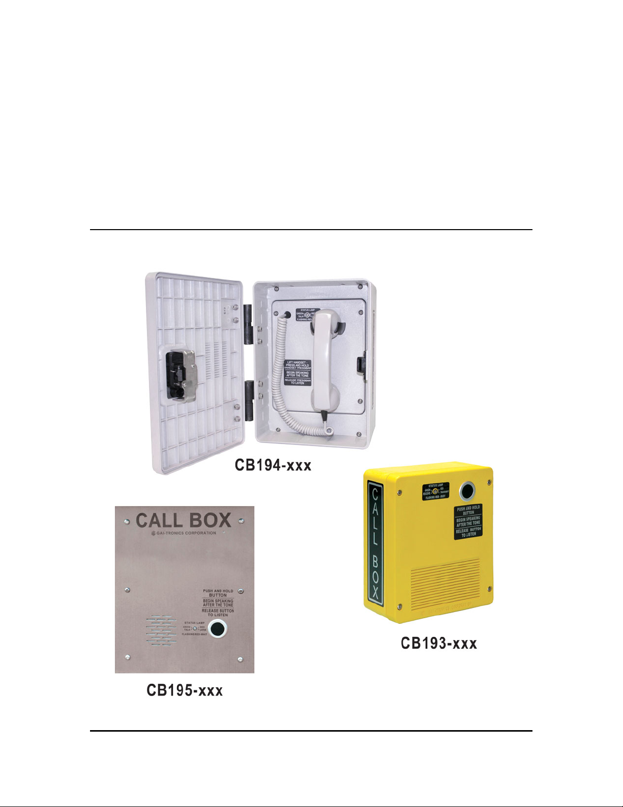
Model CB193-xxx, CB194-xxx and
CB195-xxx RF Call Boxes
Installation and Operation Manual
GAI-Tronics Corporation 400 E. Wyomissing Ave. Mohnton, PA 19540 USA
610-777-1374 800-492-1212 Fax: 610-796-5954
V
ISIT WWW.GAI-TRONICS.COM FOR PRODUCT LITERATURE AND MANUALS
Page 2

Pub. 43004-031E
GAI-TRONICS® CORPORATION
A HUBBELL COMPANY
Model CB193-xxx, CB194-xxx and
CB195-xxx RF Call Boxes
Table of Contents
Foreword.........................................................................................................................................4
Scope of Manual......................................................................................................................................4
Nomenclature..........................................................................................................................................4
Ordering Replacement Parts................................................................................................................. 4
Service and Repair.................................................................................................................................. 4
Confidentiality Notice............................................................................................................................. 5
FCC Licensing Information...................................................................................................................5
Computer Software Copyrights ............................................................................................................6
Warranty .................................................................................................................................................6
Safety and General Information ........................................................................................................... 7
Safe Handling of CMOS Integrated Circuit Devices .......................................................................... 9
RF Call Box Model Numbers and Descriptions.................................................................................10
Replacement Parts and Kits ................................................................................................................10
Programming Software and Cable (Required).................................................................................. 11
Specifications ................................................................................................................................12
Introduction...................................................................................................................................14
Functional Description.................................................................................................................16
RF Call Box-to-Radio Operation ........................................................................................................16
Call Box-to-Call Box Operation..........................................................................................................16
RF Call Box-to-Telephone Line Operation........................................................................................16
ANI Reporting.......................................................................................................................................17
Transmit Time Limiting.......................................................................................................................17
Low-Power Sleep .................................................................................................................................. 17
Battery Voltage Monitoring and Reporting....................................................................................... 18
Off-Hook Reporting (Model CB194-xxx Only) .................................................................................18
Field Installed Options/Accessories/Programming.....................................................................19
Model 190-001BB Battery Back-up Kit..............................................................................................19
Model SPK100 Solar Panel Kit ...........................................................................................................19
GAI-Tronics Corporation 400 E. Wyomissing Ave. Mohnton, PA 19540 USA
610-777-1374 800-492-1212 Fax: 610-796-5954
ISIT WWW.GAI-TRONICS.COM FOR PRODUCT LITERATURE AND MANUALS
V
Page 3

Table of Contents Pub. 43003-031E
Model XB001 External Long-Life Battery Enclosure.......................................................................19
Model GTRFP7784-108 Solar Panel Array and SPK200 Solar Panel Interface Kit .....................20
Model 190-002PS Power Supply Kit...................................................................................................20
PC Programming..................................................................................................................................21
Operation.......................................................................................................................................22
RF Call Box-to-Radio and Call Box-to-Call Box Communication Protocol...................................22
Normal Use.........................................................................................................................................................22
Transmit Channel Busy; Call Completed............................................................................................................23
Transmit Channel Busy; Call Aborted ................................................................................................................23
Transmit Time-Out .............................................................................................................................................24
Minimum Duration Transmission .......................................................................................................................24
RF Call-Box-to-Telephone Communication Protocol.......................................................................25
Normal Use.........................................................................................................................................................25
Transmit Channel Busy; Call Completed............................................................................................................26
Transmit Channel Busy; Call Aborted ................................................................................................................26
PL1877A Does Not Respond to Initialization; Call Aborted..............................................................................27
PL1877A Does Not Respond to Dialed Number; Call Aborted..........................................................................27
Phone Line Connection Not Made - Busy Signal or No Answer ........................................................................28
Transmit Time Out..............................................................................................................................................29
Installation and Mounting............................................................................................................30
Mechanical Receipt Inspection............................................................................................................30
Equipment Required ............................................................................................................................ 30
Programming.......................................................................................................................................................30
Tools ...................................................................................................................................................................30
Cable Installation Safety Considerations ........................................................................................... 30
Antenna..................................................................................................................................................30
Model CB193-xxx Push-Button RF Call Box..................................................................................... 31
Model CB194-xxx Handset RF Call Box............................................................................................ 33
Model CB195-xxx Flush-Mount RF Call Box....................................................................................35
Call Box Instruction Labeling ............................................................................................................. 37
General Set-Up..............................................................................................................................38
Hardware Configuration .....................................................................................................................38
PCBA Adjustments ............................................................................................................................................. 38
Jumper Settings................................................................................................................................................... 39
Fuses ...................................................................................................................................................................39
Connectors ..........................................................................................................................................................40
Handset Connection Table..................................................................................................................................41
Transceiver Programming Instructions (-xx1 and –xx2 Models Only)........................................... 42
Required Equipment ...........................................................................................................................................42
Programming.......................................................................................................................................................42
Set up for CB19x–xx3 Models ............................................................................................................. 43
General................................................................................................................................................................43
Install the KPG-101D Software ..........................................................................................................................44
Copying the Kenwood DAT Files.......................................................................................................................44
Programming the TK-3170 Series Radio ...........................................................................................44
GAI-Tronics Corporation 400 E. Wyomissing Ave. Mohnton, PA 19540 USA
610-777-1374 800-492-1212 Fax: 610-796-5954
ISIT WWW.GAI-TRONICS.COM FOR PRODUCT LITERATURE AND MANUALS
V
Page 4

Table of Contents Pub. 43003-031E
General Information............................................................................................................................................ 44
Connections (KPG-22 or KPG-22A Programming Cables)................................................................................44
Programming.......................................................................................................................................................44
Optional Features................................................................................................................................................45
Key Assignments.................................................................................................................................................45
Fleetsync (if utilized) ..........................................................................................................................................46
RF Call Box Jumper Settings ..............................................................................................................47
Jumper Settings (CB19x–xx3 Models Only) ......................................................................................................47
Installing the Kenwood TK-3170 Series Radio.................................................................................. 47
Programming and Set Up.............................................................................................................48
Card Suite Software Installation..................................................................................................48
RF Call Box Configuration..........................................................................................................49
RF Call Box PCBA Programming Instructions (All Models) .......................................................... 49
Required Equipment ...........................................................................................................................................49
Programming.......................................................................................................................................................49
Operational Check........................................................................................................................52
Maintenance..................................................................................................................................52
GAI-Tronics Corporation 400 E. Wyomissing Ave. Mohnton, PA 19540 USA
610-777-1374 800-492-1212 Fax: 610-796-5954
ISIT WWW.GAI-TRONICS.COM FOR PRODUCT LITERATURE AND MANUALS
V
Page 5

Pub. 43004-031E
GAI-TRONICS® CORPORATION
A HUBBELL COMPANY
Model CB193-xxx, CB194-xxx and
CB195-xxx RF Call Boxes
Foreword
Scope of Manual
This manual offers descriptive data and service information for the Model CB193-xxx, CB194-xxx, and
CB-195-xxx RF Call Boxes.
Nomenclature
The model number, located on the product identification label in the interior of the enclosure, specifically
identifies GAI-Tronics equipment.
Ordering Replacement Parts
Please include the complete identification number when ordering replacement parts or requesting
equipment information. This applies to all components, kits, and chassis. If the component part number
is not known, the order should include the number of the chassis or kit of which it is a part and sufficient
description of the desired component to identify it. Order parts from:
Customer Service
GAI-Tronics Corporation
400 E. Wyomissing Ave.
Mohnton, PA 19540
US: 800-492-1212
Outside US: 610-777-1374
Service and Repair
Inoperative or malfunctioning equipment should be returned to the factory for repair. Please call
1-800-492-1212 or 610-777-1374 to obtain a Return Authorization number, published repair prices, and
shipping instructions.
OTE: A purchase order or credit card number is required prior to processing non-warranty repairs.
N
GAI-Tronics Corporation 400 E. Wyomissing Ave. Mohnton, PA 19540 USA
610-777-1374 800-492-1212 Fax: 610-796-5954
ISIT WWW.GAI-TRONICS.COM FOR PRODUCT LITERATURE AND MANUALS
V
Page 6

Pub.: 43004-031E
Model CB193-xxx, CB194-xxx, and CB195-xxx RF Call Boxes Page
5 of 52
Confidentiality Notice
This manual is provided solely as an operational, installation, and maintenance guide and contains
sensitive business and technical information that is confidential and proprietary to GAI-Tronics.
GAI-Tronics retains all intellectual property and other rights in or to the information contained herein,
and such information may only be used in connection with the operation of your GAI-Tronics product or
system. This manual may not be disclosed in any form, in whole or in part, directly or indirectly, to any
third party.
FCC Licensing Information
Your radio operates on General Mobile Radio Service (GMRS) frequencies and is subject to the Rules
and Regulations of the Federal Communications Commission (FCC). The FCC requires that all
operators using GMRS frequencies obtain a radio license before operating their equipment. To obtain
the FCC forms, go to http://wireless.fcc.gov/services/personal/generalmobile/index.html
605 and 159, which include all forms and instructions.
Changes or modifications not approved by GAI-Tronics Corporation may void the user’s authority
granted by the FCC to operate this radio and should not be made. To comply with FCC requirements,
transmitter adjustments should be made only by or under the supervision of a person certified as
technically qualified to perform transmitter maintenance and repairs in the private land mobile and fixed
services as certified by an organization representative of the user of those services. Replacement of any
transmitter component (crystal, semiconductor, etc.) not authorized by the FCC equipment authorization
for this radio could violate FCC rules.
to obtain Forms
N
OTE: Use of this radio outside the country where it was intended to be distributed is subject to
government regulations and may be prohibited.
Federal Communications Commission (FCC)
1-202-418-0177 1-800-418-FORM
1-800-418-3676
1-888-CALL-FCC
1-888-225-5322
Or: http://www.fcc.gov
f:\radio products-current releas e\43004\43004-031e\43004-031e.doc
11/12
Page 7

Pub.: 43004-031E
Model CB193-xxx, CB194-xxx, and CB195-xxx RF Call Boxes Page
6 of 52
Computer Software Copyrights
This product contains copyrighted computer programs stored in semiconductor memory. These programs
are copyrighted by GAI-Tronics Corporation and may not be reproduced in any form without express
written permission from GAI-Tronics.
Warranty
GAI-Tronics warrants for a period of one (1) year from the date of shipment, that any GAI-Tronics equipment supplied hereunder
shall be free of defects in material and workmanship, shall comply with the then-current product specifications and product
literature, and if applicable, shall be fit for the purpose specified in the agreed-upon quotation or proposal document. If (a)
Seller’s goods prove to be defective in workmanship and/or material under normal and proper usage, or unfit for the purpose
specified and agreed upon, and (b) Buyer’s claim is made within the warranty period set forth above, Buyer may return such
goods to GAI-Tronics’ nearest depot repair facility, freight prepaid, at which time they will be repaired or replaced, at Seller’s
option, without charge to Buyer. Repair or replacement shall be Buyer’s sole and exclusive remedy, and the warranty period on
any repaired or replacement equipment shall be one (1) year from the date the original equipment was shipped. In no event shall
GAI-Tronics’ warranty obligations with respect to equipment exceed 100% of the total cost of the equipment supplied hereunder.
The applicability of any such third-party warranty will be determined solely by GAI-Tronics.
Services. Any services GAI-Tronics provides hereunder, whether directly or through subcontractors, shall be performed in
accordance with the standard of care with which such services are normally provided in the industry. If the services fail to meet
the applicable industry standard, GAI-Tronics will, for a period of one (1) year from the date of completion, re-perform such
services at no cost to the Buyer. Re-performance of services shall be Buyer’s sole and exclusive remedy, and in no event shall
GAI-Tronics’ warranty obligations with respect to services exceed 100% of the total cost of services provided hereunder.
Limitations/Exclusions. The warranty on any equipment supplied hereunder is subject to Customer’s use in compliance
with applicable FCC regulations and manufacturer specifications. The warranties herein shall not apply to, and GAI-Tronics
shall not be responsible for, any damage to the goods or failure of the services supplied hereunder, to the extent caused by
accident, misuse, abuse, neglect, system design, product modification, failure to follow instructions contained in the product
manual, repair, or attempted repair by anyone not authorized by GAI-Tronics, improper installation, installation of parts that do
not conform to the quality or specifications of the original parts or accessories, damage or loss occurred during shipment, or any
unit which is not new when sold or upon which the serial number has been defaced, modified or removed. The warranty does not
extend to damage incurred by natural causes including Force Majeure. The warranty does not cover microprocessors if failure is
due to static damage or application of improper voltage. THE WARRANTIES AND REMEDIES CONTAINED HEREIN ARE
IN LIEU OF AND EXCLUDE ALL OTHER WARRANTIES AND REMEDIES, WHETHER EXPRESS OR IMPLIED BY
OPERATION OF LAW OR OTHERWISE, INCLUDING ANY WARRANTIES OF MERCHANTABILITY OR FITNESS FOR
A PARTICULAR PURPOSE.
Operational and Maintenance Procedures. Buyer acknowledges that any improper use, maintenance, or
modification of the equipment provided hereunder, or use of unqualified maintenance or service technicians will severely impair
the operational effectiveness of the entire communication system. Buyer hereby agrees to indemnify, defend and hold GAITronics harmless from and against any and all third party claims arising, in any manner, out of: (a) Buyer’s neglect of the
equipment; (b) Buyer’s use of technicians not authorized by GAI-Tronics to service the equipment; or (c) Buyer’s improper use
or modification of the equipment or failure to follow the operational and maintenance procedures provided with the equipment.
Limitation of Liability/Damages. In no event (even should circumstances cause the exclusive warranties and remedies
set forth in the Warranty section to fail of their essential purpose) shall either party be liable for any indirect, incidental, special
or consequential damages (including, but not limited to, loss of use, loss of anticipated profits, or damages arising from delay)
whether such claims are alleged to have arisen out of breach of warranty, breach of contract, strict or absolute liability in tort, or
other act, error or omission, or from any other cause whatsoever, or any combination of the foregoing.
f:\radio products-current releas e\43004\43004-031e\43004-031e.doc
11/12
Page 8

Pub.: 43004-031E
Model CB193-xxx, CB194-xxx, and CB195-xxx RF Call Boxes Page
7 of 52
Safety and General Information
Installation should only be performed by qualified service personnel in accordance with the
National Electrical Code or applicable local codes.
Power Sources - Operate this unit only from the type of power source indicated on the label. If
• For units intended to operate from battery power, refer to operating instructions.
• For units intended to operate with External Power Supplies, use only the recommended approved
• For units intended to operate with a limited power source, this power source must comply with
Outdoor Product:
Power Lines - An outdoor system should not be located in the vicinity of overhead power lines, electric
lights, or power circuits, or where it may contact such power lines or circuits, as this contact might be
fatal. Refer to the National Electrical Code Article 800 regarding installation.
unsure of the type of power supply to use, contact qualified service personnel.
power supplies.
UL60950. Substitutions may damage the unit or cause fire or shock.
User Instructions
This equipment has been tested and found to comply with the limits for a Class A digital device, pursuant
to part 15 of the FCC Rules. These limits are designed to provide reasonable protection against harmful
interference when the equipment is operated in a commercial environment. This equipment generates,
uses, and can radiate radio frequency energy and, if not installed and used in accordance with the
instruction manual, may cause harmful interference to radio communications. Operation of this
equipment in a residential area is likely to cause harmful interference in which case the user will be
required to correct the interference at their own expense.
Exposure to Radio Frequency Energy
Your radio is designed to comply with the following standards and guidelines regarding exposure of
human beings to radio frequency electromagnetic energy:
• FCC, Code of Federal Regulations; 47 CFR part 2 sub-part J
• American National Standards Institute (ANSI)/Institute of Electrical and Electronic Engineers (IEEE)
C95.1-1992
• Institute of Electrical and Electronic Engineers (IEEE) C95.1-1999 Edition
• International Commission on Non-Ionizing Radiation Protection (ICNIRP) 1998
• Ministry of Health (Canada) Safety Code 6. Limits of Human Exposure to Radio Frequency
Electromagnetic Fields in the Frequency Range from 3 kHz to 300 GHz, 1999
f:\radio products-current releas e\43004\43004-031e\43004-031e.doc
11/12
Page 9

Pub.: 43004-031E
Model CB193-xxx, CB194-xxx, and CB195-xxx RF Call Boxes Page
8 of 52
Antenna Care
Unauthorized antennas, modifications, or attachments could damage the radio and may violate FCC
regulations.
Do NOT hold the antenna when the radio is IN USE. Holding the antenna affects the effective range.
Approved Accessories
Only use GAI-Tronics Corporation approved accessories. Please visit www.gai-tronics.com
.
Electromagnetic Interference/Compatibility
Electronic equipment may be susceptible to electromagnetic interference. If you experience interference,
visit the FCC web site at http://www.fcc.gov
for possible solutions.
Operational Cautions
Hospitals or Health Care Facilities
To avoid electromagnetic interference and/or compatibility conflicts, turn off your radio in any facility
where posted notices instruct you to do so. Hospital or health care facilities may be using equipment that
is sensitive to external RF energy.
Aircraft/Airports
Airports may be using equipment that is sensitive to external RF energy. Any use of a radio must be in
accordance with applicable regulations.
Medical Devices - Pacemakers
These recommendations are consistent with the independent research by, and recommendations of the
U.S. Food and Drug Administration. Persons with pacemakers should:
• ALWAYS keep the radio more than 6 inches (15 cm) from their pacemaker when the radio is turned
ON.
• Do NOT carry the radio in the breast pocket.
• Turn the radio OFF immediately if you have any reason to suspect that interference is taking place.
Blasting Caps and Areas
To avoid possible interference with blasting operations, turn off your radio when you are near electrical
blasting caps, in a blasting area, or in areas posted: “Turn off two-way radio.” Obey all signs and
instructions.
f:\radio products-current releas e\43004\43004-031e\43004-031e.doc
11/12
Page 10

Pub.: 43004-031E
Model CB193-xxx, CB194-xxx, and CB195-xxx RF Call Boxes Page
9 of 52
Safe Handling of CMOS Integrated Circuit Devices
Many of the integrated circuit devices used in communications equipment are of the Complementary
Metal Oxide Semiconductor (CMOS) type. Because of their high open circuit impedance, CMOS
integrated circuits are vulnerable to damage from static charges. Care must be taken handling, shipping,
and servicing them and the assemblies in which they are used.
Even though protection devices are provided in CMOS integrated circuit inputs, the protection is
effective only against overvoltage in the hundreds of volts range such as is encountered in an operating
system. In a system, circuit elements distribute static charges and load the CMOS circuits, decreasing the
chance of damage. However, CMOS circuits can be damaged by improper handling of the modules, even
in a system.
To avoid damage to circuits, observe the following handling, shipping, and servicing precautions:
1. Prior to and while servicing a circuit module, particularly after moving within the service area,
momentarily touch both hands to a bare metal, earth-grounded surface. This will discharge any static
charge that may have accumulated on the person doing the servicing.
N
OTE: Wearing a conductive wrist strap will minimize static build-up during servicing.
2. Whenever possible, avoid touching any electrically conductive parts of the circuit module with your
hands.
3. Power down the unit before installing or removing the circuit module.
4. When servicing a circuit module, avoid carpeted areas, dry environments, and certain types of
clothing (silk, nylon, etc.) because they contribute to static build-up. Similarly, disconnect the test
probe prior to removing the ground lead.
5. All electrically powered test equipment should be grounded. Apply the ground lead from the test
equipment to the circuit module before connecting the test probe.
6. If a circuit module is removed from the system, it is desirable to lay it on a conductive surface (such
as a sheet of aluminum foil) which is connected to ground through 100 k of resistance.
7. When soldering, be sure the soldering iron is grounded and has a grounded tip.
8. Prior to connecting jumpers, replacing circuit components, or touching CMOS pins (if this becomes
necessary in the replacement of an integrated circuit device), be sure to discharge any static build-up
as described in procedure 1. Since voltage differences can exist across the human body, it is
recommended that only one hand be used if it is necessary to touch pins on the CMOS device and
associated board wiring.
9. When replacing a CMOS integrated circuit device, leave the device in its conductive rail container or
conductive foam until it is to be inserted into the printed circuit module.
10. All low impedance test equipment (such as pulse generators, etc.) should be connected to CMOS
device inputs after power is applied to the CMOS circuitry. Similarly, such low impedance
equipment should be disconnected before power is turned off.
11. Replacement modules shipped separately from the factory will be packaged in a conductive material.
Any modules being transported from one area to another should be wrapped in a similar material
(aluminum foil may be used). Never use non-conductive material for packaging these modules.
f:\radio products-current releas e\43004\43004-031e\43004-031e.doc
11/12
Page 11
Pub.: 43004-031E
Model CB193-xxx, CB194-xxx, and CB195-xxx RF Call Boxes Page
10 of 52
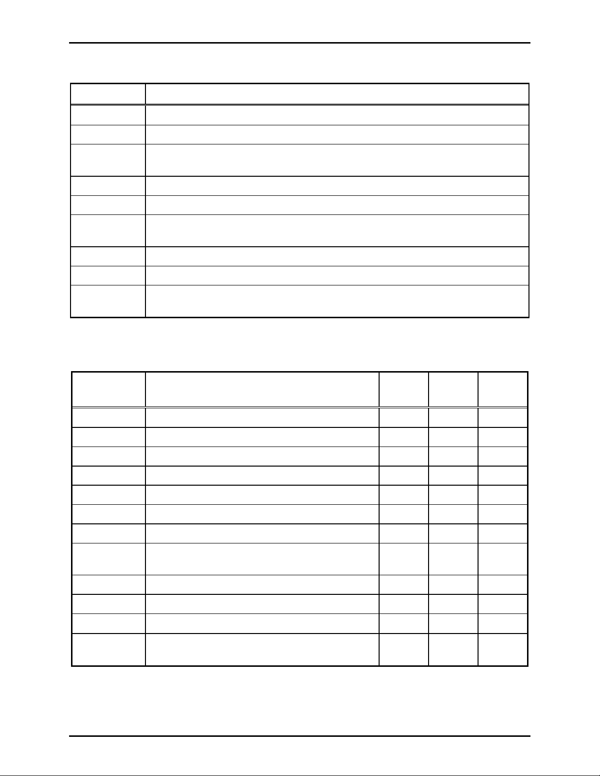
RF Call Box Model Numbers and Descriptions
Model No. Description
CB193-001 Surface-Mount Push Button, VHF (154–174 MHz)
CB193-002 Surface-Mount Push Button, UHF (450–470 MHz)
CB193-003 Surface-Mount Push Button, no radio; for use with customer-provided Kenwood TK-
3170 Series Portable Radio
CB194-001 Surface-Mount Handset with noise-canceling microphone, VHF (154–174 MHz)
CB194-002 Surface-Mount Handset with noise-canceling microphone, UHF (450–470 MHz)
CB194-003 Surface-Mount Handset, no radio; for use with customer-provided Kenwood
TK-3170 Series Portable Radio
CB195-001 Flush-Mount Push Button, VHF (154–174 MHz)
CB195-002 Flush-Mount Push Button, UHF (450–470 MHz)
CB195-003 Flush-Mount Push Button, no radio; for use with customer-provided Kenwood
TK-3170 Series Portable Radio
Replacement Parts and Kits
Part No.
Description
10111-101 Handset with Pressbar and 6-Foot Hytrel® Cord
19101-045 VHF Radio Transceiver Assembly*
19101-044 UHF Radio Transceiver Assembly*
61213-009 Cable, DB15 male to DB15 female*
69537-101 PCBA, RF Call Box
190-001BB Battery Back-up Kit
40201-004 Battery, 1.3 Ah, 12 V dc (included in 190-001BB)
40404-060 Adjustable 15 V DC Power Supply, 25 watt
(included in 190-002PS)
231-001 Pole Mounting Kit
230-001 Pole Mounting Kit (also used with XB001)
CB193-
xxx
CB194-
xxx
CB195-
xxx
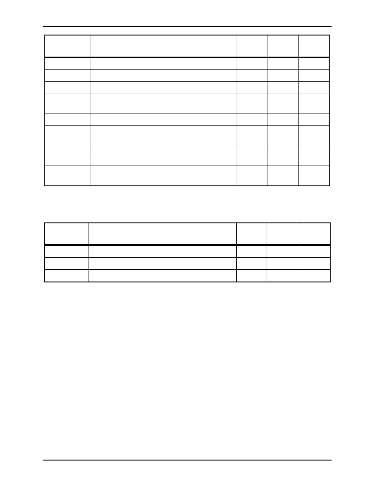
51809-009
2.5 A SloBlo Fuse 5×20 mm
190-002PS Weatherproof 15 V DC Power Supply Kit, 85–265
V ac, 50/60 Hz
f:\radio products-current releas e\43004\43004-031e\43004-031e.doc
11/12
Page 12
Pub.: 43004-031E
Model CB193-xxx, CB194-xxx, and CB195-xxx RF Call Boxes Page
11 of 52
Part No.
Description
233-001 Security Screwdriver (required)
SPK100 Solar Panel Kit (low usage applications)
SPK200 Solar Panel Interface Kit (for GTRFP7784-108)
GTRFP7784
-108
Solar Panel Array, 30 watt (medium to heavy
usage applications)
XB001 Long-life Battery Enclosure (for GTRFP7784-108)
40201-008 18 Ah Battery, 12 V dc (for XB001 and stanchion
applications)
234-
Solar Power Stanchion Assembly
GTB05005
190-3170K Kenwood TK-3170 Series Adapter Kit (only used
in -003 models)
*Not used in -003 models
Programming Software and Cable (Required)
CB193-
xxx
CB194-
xxx
CB195-
xxx
Part No.
Description
19101-024 RF Module Programming Kit (software & cable)
XAC4000A Programming Bundle CD
XAC0004A RF Call Box Programming Cable
CB193-
xxx
CB194-
xxx
CB195-
xxx
f:\radio products-current releas e\43004\43004-031e\43004-031e.doc
11/12
Page 13

Pub.: 43004-031E
Model CB193-xxx, CB194-xxx, and CB195-xxx RF Call Boxes Page
Specifications
Mechanical Specifications
CB193-xxx
Physical dimensions.......................................................................... 9.50 H × 8.00 W × 3.86 D inches
Material...................................................................................... Valox
Shipping weight......................................................................................................................... 4.5 lbs.
Color .......................................................................................................................................... Yellow
CB194-xxx
Physical dimensions........................................................................ 13.13 H × 9.39 W × 7.27 D inches
Material...................................................................................... Valox
Shipping weight....................................................................................................................... 10.5 lbs.
Color .............................................................................................................................................. Gray
CB195-xxx
Panel material .................................................................................... 14-gauge, brushed stainless steel
Panel dimensions ............................................................ 12.0 H × 10.0 W inches (304.8 × 254.0 mm)
Back box cutout dimensions............................................. 10.1 H × 7.6 W inches (255.6 × 193.0 mm)
Back box material................................................................................................ 0.060-inch aluminum
Shipping weight......................................................................................................................... 4.5 lbs.
N
OTE: Subtract .5 lbs. shipping weight for all -xx3 models.
®
(FV649 reinforced polyester)
®
(FV649 reinforced polyester)
12 of 52
Environmental Specifications
Temperature range..................................................................................................... −20° C to +60° C
Weatherproof rating.............................................................................................................. NEMA 3R
Humidity .............................................................................................................. 95% non-condensing
Audio Specifications
Audio level to RF Module............................................................................................ 50–500 mVrms
Audio level from RF Module (-xx1 and -xx2 models)............................................. 100–1200 mVrms
Audio distortion.............................................................................................................................. 1.5%
Speaker output level (CB193-xxx/CB195-xxx) .............................. 84 dB SPL at 1 meter (maximum)
Handset receiver output level (CB194-xxx).......................................................... 73 dB SPL at 1 inch
Power Specifications
Battery (40201-004 and 40201-008)
Output voltage................................................................................................................................... 12 V dc
Required charge voltage ................................................................................................................ 13.2 V dc
Cycle rating.......................................................................... 6 sec. transmit; 6 sec. receive; 10 sec. standby
1.3 Ah battery (No. 40201-004, part of 190-001BB)
Battery life (No operation) .......................................................................................................... 9 days
Battery life (2 watt output) ................................................................... 300 cycles (over 7-day period)
Battery life (5 watt output) ................................................................... 100 cycles (over 7-day period)
18 Ah battery (No. 40201-008)
Battery life (No operation) ...................................................................................................... 120 days
Battery life (2 watt output) ............................................................. 20000 cycles (over 30-day period)
Battery life (5 watt output) ............................................................... 6300 cycles (over 30-day period)
f:\radio products-current releas e\43004\43004-031e\43004-031e.doc
11/12
Page 14

Pub.: 43004-031E
Model CB193-xxx, CB194-xxx, and CB195-xxx RF Call Boxes Page
Model 40404-060 External DC Power Source (Incl uded in 190-002PS Kit)
13 of 52
Output voltage (adjustable).................................. 13.2–15.0 V dc (Set to 15.0 V for battery trickle charge)
Rated output current ........................................................................................................................ 2.1 amps
Rated output power........................................................................................................................... 25 watts
Input voltage ............................................................................................................ 85–264 V ac, 50–60 Hz
Input current................................................................................................ 0.7 A/115 V ac, 0.4 A/230 V ac
RF Module (CB19x-001/CB19x-002)
General
Frequency range............................................................................................................ VHF: 154–174 MHz
UHF: 450–470 MHz
Antenna impedance................................................................................................................................ 50 Ω
Antenna connection ............................................................................................................................... BNC
Operating voltage........................................................................................... 8–15 V dc, 13.8 V dc nominal
Encoder/decoder ................................................................................................... CTCSS tone, DCS digital
Receiver (measurement procedures made per ANSI/TIA/EIA-603)
Sensitivity (12 dB SINAD)............................................................................................................... 0.25 µV
Inter-modulation ....................................................................................... VHF @ −65 dB; UHF @ −60 dB
Audio output ................................................................................... 700 mVrms with 3 kHz-deviated signal
Transmitter (measurement procedures made per ANSI/TIA/EIA-603)
RF output .................................................................................................................................... 2 or 5 watts
Spurious and harmonic emissions............................................................................... < −20 dBm maximum
Audio input ........................................................................................ 300 mVrms for 3 kHz-deviated signal
Modulation sensitivity ................................................................................... 100 mVrms @ 60% peak dev.
Approvals
FCC Identifier............................................................................................................. VHF: AIERT 17–142
UHF: AIERT 17–442
FCC Compliance................................................................................................................................. Part 90
IC Certification ....................................................................................................... VHF: 1084A-RIT 17142
UHF: 1084A-RIT 17442
f:\radio products-current releas e\43004\43004-031e\43004-031e.doc
11/12
Page 15
Pub.: 43004-031E
Model CB193-xxx, CB194-xxx, and CB195-xxx RF Call Boxes Page
14 of 52
Introduction
The GAI-Tronics RF Call Boxes are designed for isolated areas requiring voice communication
equipment, using wireless RF technology to provide half-duplex communication. These units are ideal
for areas where underground or overhead cabling is undesirable or not available. The simple push-totalk, release-to-listen operation provides user-friendly functionality, and these designs are extremely
resistant to vandalism.
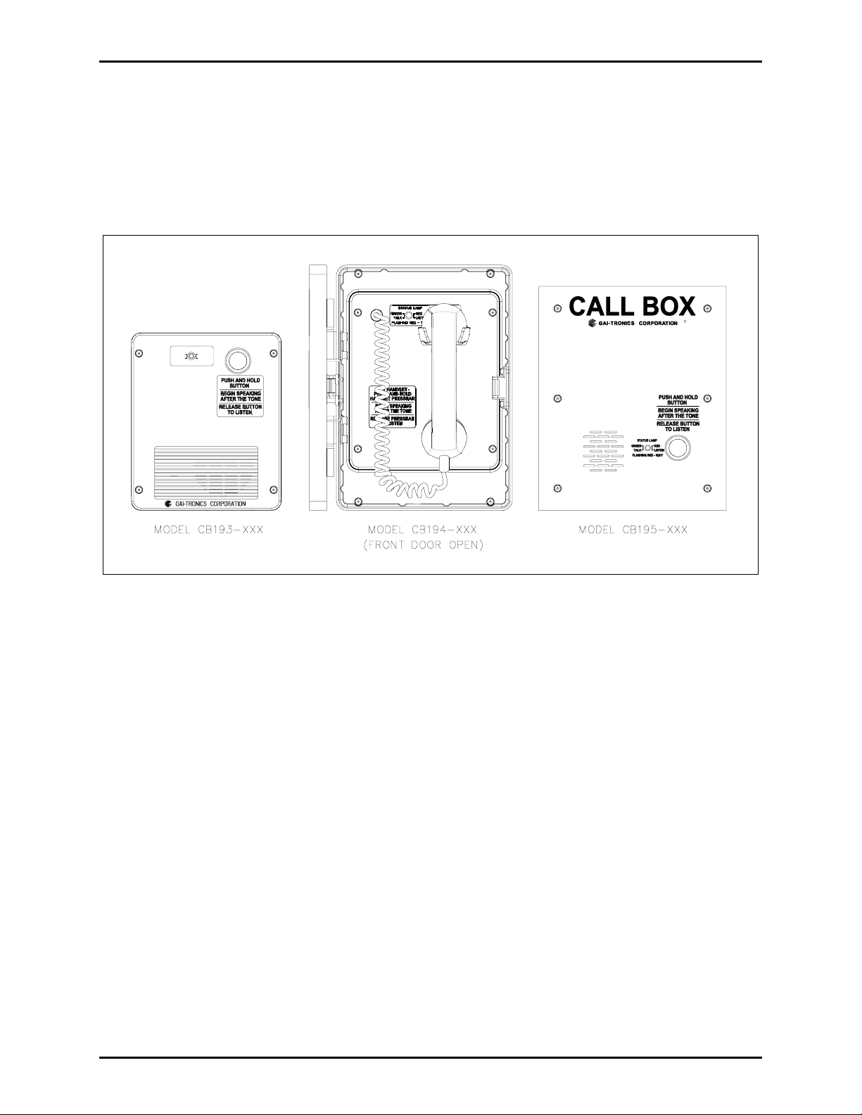
STATUS LAMP
RED
GREEN
LISTEN
TALK
FLASHING RED - WAIT
Figure 1. Model CB193-xxx, CB194-xxx, and CB195-xxx Outline Drawing
The Model CB193-xxx Push-Button RF Call Box (yellow) and CB194-xxx Handset RF Call Box (gray)
enclosures are constructed of durable Valox
®
material, and have a weatherproof rating of NEMA 3R
when installed according to directions. The CB193-xxx and CB194-xxx RF Call Boxes can be wallmounted or mounted to a pole measuring 1 to 4 inches in diameter using the Model 230-001 or the Model
231-001 Pole Mounting Kit.
The Model CB195-xxx Flush-Mount RF Call Box is equipped with these same features, but is housed in
a brushed stainless steel flush-panel enclosure rated NEMA 3R that is designed for flush mounting. This
can be done within any wall cavity or by using the GAI-Tronics Model 234 Series stanchions.
f:\radio products-current releas e\43004\43004-031e\43004-031e.doc
11/12
Page 16

Pub.: 43004-031E
Model CB193-xxx, CB194-xxx, and CB195-xxx RF Call Boxes Page
15 of 52
The Model CB193-xxx and Model CB195-xxx include a push-to-talk (PTT) button, an LED status
indicator lamp, an integral speaker and a microphone. The Model CB194-xxx includes a handset with
noise-canceling microphone and an integral PTT pressbar and features a magnetic proximity hookswitch
for handset sensing.
The status lamp indicates the transmit/receive (talk/listen) status of the call box and provides indication
when the channel is busy (wait - flashing red), or if a low battery power condition exists (flashing amber
every 8 seconds).
All RF Call Box models can be programmed for call box-to-radio, call box-to-call box, or call box-totelephone line operation via the CARD Suite Software application. All modes of operation require a
receiving radio to complete the system (handheld, mobile, or base station). For call box-to-telephone line
operation, a GAI-Tronics PL1877A (MRTI 2000) Telephone Interconnect is additionally required to
interface the receiving radio’s signal to the telephone line via a host radio. The call box-to-call box mode
of operation can provide a common communication link (all units commonly broadcast received audio
transmission) between call boxes. In this configuration, all RF Call Boxes must be programmed for
“Standby Forever” operation and will require a constant external power source.
These units are programmed using the CARD Suite Software application, which is included on the
XAC4000A Programming Bundle CD. Each unit can be bench-programmed prior to installation, thus
limiting field installation time. The Model 19101-024 Programming Kit is additionally required for
programming the frequency and PL code into the integral radio transceiver (-001 and -002 models only).
The optional Model SPK100 Solar Panel Kit, Model GTRFP7784-108/SPK200 Solar Panel Array and
Interface Kit, and the 190-002PS Power Supply Kit are available for use with all models. See the “Field
Installed Optional Accessories” section on page 19 and Model 190-002PS installation instructions on
page 20 for additional information.
All Models CB19x-001 and CB19x-002 are provided with a factory-installed, integral RF transceiver.
These units are ready for programming and system activation without the need for additional circuitry.
The Model CB19x-003 is provided without RF circuitry. These units will require the installation of a
customer-provided Kenwood TK-3170 Series Portable Radio and Model 190-3170K Adapter Kit prior to
system activation.
f:\radio products-current releas e\43004\43004-031e\43004-031e.doc
11/12
Page 17

Pub.: 43004-031E
Model CB193-xxx, CB194-xxx, and CB195-xxx RF Call Boxes Page
16 of 52
Functional Description
Each GAI-Tronics RF Call Box is typically in a low-power sleep mode when not in use (factory default
setting). In this state, the radio is powered down and all audio circuitry is disabled. The processor is in a
low-power sleep mode, waking periodically to check the battery voltage. The sleep mode can be disabled
via the CARD Suite Software to provide receive capability at all times (call box-to-radio or call box-tocall box operation only.) In this mode, the Call Box must be connected to a constant 13.8 V dc supply
(or 12 V dc if battery is not used.) When used for call box-to-telephone operation, there is no need to
disable the sleep mode as all calls must be initiated by the RF Call Box.
RF Call Box-to-Radio Operation
Pressing the PTT button or the handset pressbar removes the Call Box from the low-power sleep mode
and enables the radio and the audio circuitry. The front panel status lamp lights red, while the Call Box
momentarily monitors the transmit channel for activity, and (when ANI is enabled) broadcasts its
programmed ANI code if there is no other radio traffic.
When the radio traffic is clear and after transmitting the ANI code, a “go-ahead” splash tone is generated
over the speaker or handset receiver and the front panel status lamp turns green. Speak in a normal voice
at arm’s length distance from the push button models or into the handset microphone while holding the
pressbar. When finished, release the button or pressbar. The radio ceases transmission and waits for
receive audio. The front panel status lamp lights red whenever receive audio is present.
Continue conversation in this push-to-talk, release-to-listen manner. After conversation has ended, the
RF Call Box returns to sleep mode with the absence of carrier activity after a preprogrammed amount of
time (factory set at 10 seconds).
Call Box-to-Call Bo x Operation
In this operation application, the RF Call Box will function similarly to the RF Call Box-to-Radio
operation, as each Call Box is actually a radio. Operation is push-to-talk/release-to-listen and the
transmitting Call Box first monitors the transmit channel and provides a busy signal (if busy) or “goahead” splash tone if the channel is clear. In this mode of operation, the ANI feature is not used, and the
RF Call Box will not “go to sleep” to conserve power (must be programmed for “Standby Forever”
operation). A constant external power source is required.
RF Call Box-to-T elephone Line Operation
In the call box-to-telephone line operational mode, a phone call is initiated by momentarily pressing and
releasing the PTT button or handset pressbar. The front panel status lamp flashes red indicating a wait
signal. During this time period, the RF Call Box is interfacing with the Model PL1877A Telephone
Interconnect. When the telephone interconnect is accessed, the RF Call Box dials a pre-programmed
telephone number. When the phone line is accessed, the front panel status lamp changes to a steady red.
A ringing or a busy signal will be heard on the speaker or handset receiver.
f:\radio products-current releas e\43004\43004-031e\43004-031e.doc
11/12
Page 18

Pub.: 43004-031E
Model CB193-xxx, CB194-xxx, and CB195-xxx RF Call Boxes Page
17 of 52
After the person answering the phone can be heard speaking, press the PTT button or handset pressbar to
respond. When the PTT button is pressed, the front panel status lamp lights green as a signal to talk.
Speak in a normal tone of voice at arm’s length distance from the push button models or into the handset
microphone while holding the pressbar. Release the button or pressbar when finished speaking. The
radio ceases transmission and waits for receive audio. The front panel status lamp returns to steady red
whenever receive audio is present. Continue conversation in a push-to-talk, release-to-listen operation.
The telephone line disconnects after no carrier activity is detected after a pre-programmed time period.
The RF Call Box returns to sleep mode as stated under call box-to-radio operation.
ANI Reporting
A programmable multi-digit ANI code (DTMF) is reported by each unit upon initial PTT activation, if
the unit is programmed for ANI operation. The length of this code is adjustable between two and eight
digits via the CARD Suite Software. The ANI code is only transmitted on the first PTT of a call upon
awakening from sleep mode, unless programmed to transmit on each PTT activation. This reporting
operation requires the use of a receiving device that can decode the transmitted DTMF ANI code
(portable, mobile, or remote desk set or console). N
the call box-to-telephone line or call box-to-call box operation.
OTE: Identification ANI reporting is not available in
Transmit Time Limiting
The transmit time is limited in several ways. First, a momentary depression of the button to initiate a call
results in a minimum duration transmit. The Call Box remains in transmit for a duration long enough for
the entire ANI code to be transmitted followed by a programmable amount of open microphone transmit
time (factory set at 4 seconds). This allows emergency depression and release of the button, yet still
provides the user with a period of time to speak or for the receiving party to hear ambient sounds. For
additional transmit cycles in the same call, the user must press and hold the PTT switch during transmit.
N
OTE: Minimum transit time is not available in call box-to-telephone line operation.
The second transmit time limitation is a maximum transmit time. This duration, which is factory set to
20 seconds, prevents the radio from being damaged and also preserves battery life. When this maximum
time is reached, the PTT button must be released and re-activated to begin transmitting again. Both
transmit time durations are software programmable via the CARD Suite Software.
Low-Po wer Sleep
A call is terminated when the Call Box returns to its low-power sleep mode or when no receive audio is
present. The controller PCBA disables all of the audio circuitry and places the micro-controller in a lowpower sleep mode. In the sleep mode, power is removed from the radio module to limit current draw
from the power supply or battery to 6 mA.
The Call Box enters its low-power sleep mode after a period of inactivity (no carrier detect and no PTT).
The length of this period (standby time) is preprogrammed using the CARD Suite Software application.
The Call Box wakes from sleep by a PTT activation. As previously stated, the sleep mode operation can
be disabled to provide continuous receive capability (Standby Forever).
f:\radio products-current releas e\43004\43004-031e\43004-031e.doc
11/12
Page 19

Pub.: 43004-031E
Model CB193-xxx, CB194-xxx, and CB195-xxx RF Call Boxes Page
18 of 52
Battery Voltage Monitoring and Reporting
The micro-controller monitors the voltage on the battery by use of an analog-to-digital converter. The
battery voltage is sampled every 6 hours. If low battery voltage is detected, the Call Box transmits its
ANI and a low battery code (‘*LB’ = ‘*52’) via the radio. Once this report is made, the Call Box status
lamp turns amber and blinks for 0.25 second every 8 seconds until the battery is charged or replaced. As
noted in the ANI reporting paragraph, a DTMF decoding device will be required at the receiving end of
the Call Box transmission.
In call box-to-telephone line operation, a low battery ANI code is not transmitted. However, the Call
Box status lamp turns amber and blinks for 0.25 second every 8 seconds until the battery is charged or
replaced. In conjunction with the status lamp indication, the RF Call Box transmits a low battery alert
tone that is audible to the telephone user (if programmed for this operation). This tone is broadcast in
unison with the flashing status lamp. A telephone operator must be “online” with the RF Call Box to
hear this alert tone.
Off-Hook Reporting (Model CB194-xxx Only)
The Model CB194-xxx RF Call Box is fitted with a magnetic proximity hookswitch for handset sensing.
Activation of this sensor wakes the Call Box and initiates transmission of the programmed ANI code. If
the handset remains off-hook for an extended period following the termination of a call, or if no call is
initiated after the handset is taken off-hook, the Call Box again transmits its ANI and an off-hook alert
code (‘*OH’ = ‘*64’). As noted in the ANI reporting paragraph, a DTMF decoding device will be
required at the receiving end of the Call Box transmission.
N
OTE: Off-hook ANI reporting is not available in call box-to-telephone line operation.
f:\radio products-current releas e\43004\43004-031e\43004-031e.doc
11/12
Page 20

Pub.: 43004-031E
Model CB193-xxx, CB194-xxx, and CB195-xxx RF Call Boxes Page
19 of 52
Field Installed Options/Accessories/Programming
Model 190-001BB Battery Back-up Kit
The Model 190-001BB Battery Back-up Kit provides 12 V dc power if main power is lost or
disconnected. The kit includes a bracket, Model 40201-004 1.3 Ah battery, two mounting screws, and a
gasket pad. The battery provides 300 cycle uses over a 7-day period @ 2 watt power setting and 100
cycle uses over a 7-day period @ 5 watt power setting, without the application of power. Refer to
Publication 43003-042 for installation details.
Model SPK100 Solar Panel Kit
The Model SPK100 Solar Panel Kit should be used for low usage Call Box applications (emergency type
applications) when an external power source is not available or feasible. This kit must be used with the
Model 190-001BB Battery Back-up Kit installed inside the RF Call Box. The Model SPK100 Kit
includes a solar panel array (5 watts) with a 10-foot connecting cable, a charge regulator module, and the
necessary mounting hardware for surface or pole mounting. The regulator module is mounted inside the
enclosure for all RF Call Box models. Refer to Pub. 43003-043 for installation instructions.
N
OTE: The Model 40408-009 Battery Charger should be used to charge the 40201-009 battery (included
in the 190-001BB Kit) prior to installation in solar power applications.
Model XB001 External Long-Life Battery Enclosure
The Model XB001 External Long-Life Battery Enclosure includes a NEMA-4 weatherproof enclosure
with battery mounting bracket, a sealed 12 V dc external receptacle, and mating power connection cable.
The required Model 40201-008 18 Ah battery is purchased separately. This kit allows the RF Call Box
to be installed within 2 feet of the XB001 enclosure for true battery-powered operation.
Combining this kit with the Model SPK200 Solar Panel Interface Kit and Model GTRFP7784-108 Solar
Panel will provide a completely wireless operation. If the application is only temporary, the speaker can
easily be “unplugged” from the battery enclosure and relocated or stored. Refer to Pub. 43003-037 for
installation details.
N
OTE: Model 40408-011 Battery Charger should be used for charging the 40201-008 battery in solar or
battery-only applications.
f:\radio products-current releas e\43004\43004-031e\43004-031e.doc
11/12
Page 21

Pub.: 43004-031E
Model CB193-xxx, CB194-xxx, and CB195-xxx RF Call Boxes Page
20 of 52
Model GTRFP7784-108 Solar Panel Array and SPK200 Solar Panel
Interface Kit
The Model GTRFP7784-108 Solar Panel Array (30 W) and Model SPK200 Solar Interface Kit must be
used with the Model XB001 External Long-life Battery Enclosure and 40201-008 (18 Ah) battery. The
solar array and kit provide battery recharging when an external power source is not available. This solar
option should be used for medium to heavy RF Call Box usage (9
th
tee box, high-traffic gate entry, etc.)
The GTRFP7784-108 is provided with an integral 15-foot connecting cable and the SPK200 is supplied
with a terminal block, battery charge regulator module, solar array mounting bracket, wiring harness, and
the necessary mounting hardware for the components. Refer to Pub. 43003-039 for solar panel
installation instructions.
Model 190-002PS Pow er Supply Kit
The Model 190-002PS Power Supply Kit is designed for mounting to the bottom of a CB193-xxx or
CB194-xxx RF Call Box. The kit includes a two-gang weatherproof electrical box, 15 V dc power
supply, mounting bracket, 3-inch pipe nipple, ½-inch NPT conduit hub, security hardware, and security
bit (T15 Torx).
Figure 2. Model 190-002PS Power Supply Kit Components
f:\radio products-current releas e\43004\43004-031e\43004-031e.doc
11/12
Page 22

Pub.: 43004-031E
Model CB193-xxx, CB194-xxx, and CB195-xxx RF Call Boxes Page
21 of 52
To properly charge the back-up battery (if required), the 40404-060 power supply (included in the kit)
must be set for 15.0 V dc output. This output can be adjusted at the voltage adjustment potentiometer
labeled ADJ. Refer to Figure 2 for wire connections.
Figure 3. Power Supply Wiring Connections
PC Programming
All RF Call Boxes require the use of the CARD Software application (included on the XAC4000A
Programming Bundle CD) and the XAC0004A Programming Cable for the Call Box non-default settings.
The Model CB193-001, CB193-002, CB194-001, CB194-002, CB195-001 and CB195-002 RF Call
Boxes additionally require the use of the 19101-024 RF Module Programming Kit. This kit includes a
separate cable and software for programming the RF Module’s operating frequency and TPL/DPL code.
Refer to the programming instructions on page 42 of this manual.
The CARD Suite Software application is used to program the Call Box PCBA. The ANI code,
minimum/maximum user timeouts, sleep enable/disable, “go-ahead” tone, volume, DTMF transmit level,
and stand-by times are all configurable through the CARD Suite Software application.
f:\radio products-current releas e\43004\43004-031e\43004-031e.doc
11/12
Page 23

Pub.: 43004-031E
Model CB193-xxx, CB194-xxx, and CB195-xxx RF Call Boxes Page
Operation
RF Call Box-to-Radio and Call Bo x-to-Call Box Communica tion
Protocol
Normal Use
Step Action Response
22 of 52
1 User presses and holds the
PTT button (CB194-xxx remove handset first)
2 No transmit channel
activity detected
3 ANI transmission complete Call Box emits a “go-ahead” splash tone over the speaker or
4 User speaks into the
microphone
5 User releases PTT button
6 Carrier is detected by radio Incoming audio is broadcast over the Call Box speaker or handset
7 Call Box detects no carrier
8 Call Box detects a lack of
PTT or carrier detect
activity for the programmed
duration
Call Box wakes from low-power sleep mode, checks transmit
channel activity and the status lamp lights red to indicate a “wait”
period.
Call Box keys radio and transmits ANI code.
handset receiver, and the status lamp lights green as a signal to
begin talking.
Call Box transmits audio over the radio while timing the transmit
duration.
Call Box un-keys the radio and the status lamp is off.
receiver and the status lamp lights red as a signal to listen (receive
audio present).
Status lamp is off. User may press PTT button and speak into the
microphone.
Call Box terminates the call by powering down the radio and
audio circuitry. The status light is off and the unit returns to its
low-power sleep mode.
f:\radio products-current releas e\43004\43004-031e\43004-031e.doc
11/12
Page 24

Pub.: 43004-031E
Model CB193-xxx, CB194-xxx, and CB195-xxx RF Call Boxes Page
Transmit Channel Busy; Call Completed
Step Action Response
23 of 52
1 User presses the PTT
button (momentary or
maintained)
2 Transmit channel activity
detected
3 User continues to depress
the PTT button until the
channel is available
Call Box wakes from low-power sleep mode, checks transmit
channel activity, and status lamp lights red to indicate that the
channel is busy (wait period).
The Call Box status lamp flashes red for a pre-programmed amount
of time before again checking transmit channel activity.
Call Box proceeds as in steps 2 through 7 in “Normal Use” section.
OTE: If the PTT button is momentarily pressed, the RF Call Box
N
automatically enters the minimum transit time, proceeding as in
steps 2 through 7 in the “Normal Use” section after the channel has
cleared.
Transmit Channel Busy; Call Aborted
Step Action Response
1 User presses the PTT
button
2 Transmit channel activity
Call Box wakes from low power sleep mode, checks transmit
channel activity.
Call Box status lamp flashes red indicating a busy channel (wait).
detected
3 User releases PTT button
while the channel is busy
Call Box powers down the radio and audio circuitry (after auto
connect time-out has expired). The status lamp is off and the unit
returns to its low-power sleep mode.
OTE: If the PTT button is momentarily pressed, the RF Call Box
N
automatically returns to sleep mode after auto-connect time-out has
expired.
f:\radio products-current releas e\43004\43004-031e\43004-031e.doc
11/12
Page 25

Pub.: 43004-031E
Model CB193-xxx, CB194-xxx, and CB195-xxx RF Call Boxes Page
Transmit Time-Out
Step Action Response
1 User presses PTT button Call Box wakes from low-power sleep mode, checks transmit
channel activity, and the status lamp lights red to indicate unit is
operating in RX mode.
24 of 52
2 No transmit channel
Call Box keys radio and transmits ANI code.
activity detected
3 ANI transmission
complete
Call Box emits a “go-ahead” splash tone over the speaker or
handset receiver, and the status lamp lights green as a signal to
talk.
4 User speaks into the
microphone
5 Maximum transmit time
reached
Call Box transmits audio over the radio while timing the transmit
duration.
Call Box un-keys the radio, the status lamp is off, and it emits a
“transmission-terminated” tone over the speaker or handset
receiver. The user must now release and repress the PTT button in
order to continue transmission.
6 User releases PTT button Call Box proceeds as in steps 2 through 7 in “Normal Use” section.
Minimum Duration Transmission
Step Action Response
1 User presses and releases
the PTT button
(momentary activation)
Call Box wakes from low-power sleep mode, checks transmit
channel activity, and the status lamp lights red to indicate a “wait”
period.
2 No transmit channel
Call Box keys radio and transmits ANI code.
activity detected
3 ANI transmission
complete
4 User speaks into the
microphone
5 Minimum transmit time
reached
Call Box emits a “go-ahead” slash tone over the speaker or handset
receiver, and the status lamp lights green as a signal to talk.
Call Box transmits audio over the radio while timing the transmit
duration.
Call Box un-keys the radio, the status lamp is off, and it emits a
“transmission-terminated” tone over the speaker or handset
receiver. The user must now press and hold the PTT button in
order to continue transmission.
f:\radio products-current releas e\43004\43004-031e\43004-031e.doc
11/12
Page 26

Pub.: 43004-031E
Model CB193-xxx, CB194-xxx, and CB195-xxx RF Call Boxes Page
25 of 52
RF Call-Box-to-T elephone Communication Protocol
In all of the use cases described in the tables below, the call can be discontinued at any time when using
the Model CB194-xxx Handset RF Call Box. If the handset is put in the on-hook position, the Call Box
searches for no channel activity and disables the PL1877A Telephone Interconnect (MRTI 2000) from
continuing the phone connection. When using Models CB193-xxx and CB195-xxx (push-button
versions), the call is discontinued following the time-out constraints programmed in the Call Box and
PL1877A.
Normal Use
Step Action Response
1 User presses and releases PTT
button (momentary)
Call Box wakes from low-power sleep mode, checks transmit
channel activity and status lamp slowly flashes red to
indicate unit is operating.
2 No transmit channel activity
detected
Call Box keys radio and initiates communication with
PL1877A. Status lamp continues to slowly flash red to
indicate unit is operating.
3 PL1877A detected and dials
phone number
4 Number dialed complete
Call Box dials preprogrammed number. Status lamp slowly
flashes red to indicate unit is operating.
Status lamp stops flashing red. Ring or busy signal is
broadcast over speaker.
5 Phone connection complete Incoming audio is broadcast over the Call Box speaker or
handset receiver and the status lamp lights steady red as a
signal to wait and listen (receive audio present).
6 User presses and holds PTT
button (maintained)
Call Box keys the radio and checks transmit channel activity.
The status lamp lights red to indicate “wait” period. With no
activity detected, a “go-ahead” splash tone is heard on the
speaker or handset receiver and the status lamp lights green
as a signal to begin talking. Call Box transmits audio to
PL1877A while timing the transmit duration.
7 User releases PTT button
Call Box un-keys the radio and the status lamp is off.
8 Carrier is detected by radio Incoming audio is broadcast over the Call Box speaker or
handset receiver and the status lamp lights steady red as a
signal to wait and listen (receive audio present).
9 Call Box detects a lack of PTT
or carrier detect activity for
the programmed duration
The status lamp flashes red, the Call Box terminates the call
with the PL1877A, and emits three tones to the speaker. Call
Box terminates the call by powering down the radio and
audio circuitry. The status light is off and the unit returns to
its low-power sleep mode.
f:\radio products-current releas e\43004\43004-031e\43004-031e.doc
11/12
Page 27

Pub.: 43004-031E
Model CB193-xxx, CB194-xxx, and CB195-xxx RF Call Boxes Page
Transmit Channel Busy; Call Completed
Step Action Response
26 of 52
1 User presses and releases PTT
button
Call Box wakes from low-power sleep mode, checks transmit
channel activity, and status lamp slowly flashes red to
indicate unit is operating.
2 Transmit channel activity is
detected
The Call Box status lamp rapidly flashes red for a pre-
programmed amount of time before again checking transmit
channel activity.
3 Transmit channel becomes
available
Call Box proceeds as in steps 2 through 9 in “Normal Use”
section.
Transmit Channel Busy; Call Aborted
Step Action Response
1 User presses and releases PTT
button
Call Box wakes from low-power sleep mode, checks transmit
channel activity and status lamp slowly flashes red to indicate
unit is operating.
2 Transmit channel activity
detected
3 Channel activity detected past
pre-programmed time duration
Call Box status lamp rapidly flashes red indicating a busy
channel (wait).
The status lamp flashes red, and the call box emits three tones
to the speaker. Call Box terminates the call by powering
down the radio and audio circuitry. The status light is off and
the unit returns to its low-power sleep mode.
f:\radio products-current releas e\43004\43004-031e\43004-031e.doc
11/12
Page 28

Pub.: 43004-031E
Model CB193-xxx, CB194-xxx, and CB195-xxx RF Call Boxes Page
PL1877A Does Not Respond to Initialization; Call Aborted
Step Action Response
27 of 52
1 User presses and releases PTT
button
Call Box wakes from low power sleep mode, checks transmit
channel activity and status lamp slowly flashes red to
indicate unit is operating.
2 No transmit channel activity
detected
Call Box keys radio and initiates communication with
PL1877A. Status lamp slowly flashes red to indicate unit is
operating.
3 PL1877A not detected and
terminates call
The status lamp flashes red, the Call Box terminates the call
with the PL1877A, and emits three tones to the speaker. Call
Box terminates the call by powering down the radio and
audio circuitry. The status light is off and the unit returns to
its low-power sleep mode.
PL1877A Does Not Respond to Dialed Number; Call Aborted
Step Action Response
1 User presses and releases PTT
button
Call Box wakes from low power sleep mode, checks transmit
channel activity and status lamp slowly flashes red to
indicate unit is operating.
2 No transmit channel activity
detected
Call Box keys radio and initiates communication with
PL1877A. Status lamp slowly flashes red to indicate unit is
operating.
3 PL1877A detected and dials
phone number
4 PL1877A did not respond to
numbers dialed and terminates
call
Call Box dials preprogrammed number. Status lamp slowly
flashes red to indicate unit is operating.
The status lamp flashes red, the Call Box emits three tones to
the speaker. Call Box terminates the call by powering down
the radio and audio circuitry. The status light is off and the
unit returns to its low-power sleep mode.
f:\radio products-current releas e\43004\43004-031e\43004-031e.doc
11/12
Page 29

Pub.: 43004-031E
Model CB193-xxx, CB194-xxx, and CB195-xxx RF Call Boxes Page
Phone Line Connection Not Made - Busy Signal or No Answer
Step Action Response
28 of 52
1 User presses and releases
PTT button
2 No transmit channel activity
detected
3 PL1877A detected and dials
phone number
4 Phone number has been
dialed
5 Call not answered or busy
signal
6 Call Box detects a lack of
PTT or carrier detect activity
for the programmed duration
Call Box wakes from low power sleep mode, checks transmit
channel activity and status lamp slowly flashes red to
indicate unit is operating.
Call Box keys radio and initiates communication with
PL1877A. Status lamp slowly flashes red to indicate unit is
operating.
Call Box dials preprogrammed number. Status lamp slowly
flashes red to indicate unit is operating.
Status lamp stops flashing red. Ring or busy signal is
broadcast over speaker.
PL1877A time out occurs (defined in PL1877A manual) and
PL1877A discontinues transmission to Call Box.
The status lamp flashes red, the Call Box terminates the call
with the PL1877A, and emits three tones to the speaker. Call
Box terminates the call by powering down the radio and
audio circuitry. The status light is off and the unit returns to
its low-power sleep mode.
f:\radio products-current releas e\43004\43004-031e\43004-031e.doc
11/12
Page 30

Pub.: 43004-031E
Model CB193-xxx, CB194-xxx, and CB195-xxx RF Call Boxes Page
Transmit Time Out
Step Action Response
29 of 52
1 User presses and releases PTT
button
Call Box wakes from low-power sleep mode, checks transmit
channel activity and status lamp slowly flashes red to indicate
unit is operating.
2 No transmit channel activity is
detected
Call Box keys radio and initiates communication with
PL1877A. Status lamp slowly continues to flash red to
indicate unit is operating.
3 PL1877A is detected and Call
Box dials phone number
4 Number dialed complete
Call Box dials preprogrammed number. Status lamp slowly
flashes red to indicate unit is operating.
Status lamp stops flashing red. Ring or busy signal is
broadcast over speaker.
5 Phone connection complete Incoming audio is broadcast over the Call Box speaker or
handset receiver and the status lamp lights steady red as a
signal to wait and listen (receive audio present).
6 User presses PTT button Call Box keys the radio and checks transmit channel activity.
The status lamp lights red to indicate “wait” period. With no
activity detected, a “go-ahead” splash tone is heard on the
speaker or handset receiver and the status lamp lights green as
a signal to begin talking. Call Box transmits audio to
PL1877A while timing the transmit duration.
7 User speaks into the
microphone
Call Box transmits audio over the radio and times the transmit
duration.
8 Maximum transmit time
reached
9 Transmit channel becomes
available
Call Box un-keys the radio, the status lamp is off, and it emits
a “transmission-terminated” tone over the speaker or handset
receiver. The user must now release and repress the PTT
button in order to continue transmission.
Call Box proceeds as in steps 5 through 9 in “Normal Use”
section.
f:\radio products-current releas e\43004\43004-031e\43004-031e.doc
11/12
Page 31

Pub.: 43004-031E
Model CB193-xxx, CB194-xxx, and CB195-xxx RF Call Boxes Page
30 of 52
Installation and Mounting
Mechanical Receipt Inspection
All RF Call Boxes are shipped in a cardboard container, protected from movement and distress by a selfforming packaging material. Thoroughly inspect it as soon as possible after delivery. In-transit damage
should be immediately reported to the transportation company.
Equipment Required
Programming
• PC with Windows 95 or newer operating system
OTE: CARD Suite is not compatible with Windows NT)
(N
• Card Suite Programming Software (all models)
• XAC0004A Programming Cable (all models)
• 19101-024 RF Programming Kit (-001 and -002 models only)
Tools
• #1 Phillips screwdriver
• GAI-Tronics Model 233-001 Security Screwdriver (Torx T-25)
• 1/16-inch flat blade screwdriver (for remote volume and transmit level control only)
Cable Installation Safety Considerations
Interconnecting, communications, and Class 2 dc power cables should be separated from electrical light
or other Class 1 circuits by at least 2 inches. The exception is where Class 1 wiring or power circuits are
run in a raceway, or are metal-sheathed or metal-clad, or are permanently separated from the conductors
of the other circuitry by a continuous and firmly fixed nonconductor such as porcelain tubes or flexible
tubing in addition to the insulation on the wire. Communications cables and in-building wiring should be
listed and marked for the purpose according to NEC Article 800.
N
OTE: If an external antenna is used, antenna cable must be routed through a dedicated enclosure entry
point, separated from power wiring.
Antenna
All Call Box models equipped with an integral radio transceiver require the use of an external antenna.
The use of an internal antenna may prevent the Call Box from operating. An omni-directional, unity gain
antenna is recommended for general use.
f:\radio products-current releas e\43004\43004-031e\43004-031e.doc
11/12
Page 32

Pub.: 43004-031E
Model CB193-xxx, CB194-xxx, and CB195-xxx RF Call Boxes Page
31 of 52
Model CB193-xxx Push-Button RF Call Box
1. Loosen the four security screws from the front panel assembly using the GAI-Tronics Model 233-001
Security Screwdriver (sold separately).
2. Open the front panel of the enclosure, which is hinged on the left. Remove the front cover from the
rear enclosure by pulling straight out. (The hinges should remain attached to the front cover, pulling
out of the back box.) Carefully place the front panel assembly in a safe location while installing the
back box. The left side mounting holes are located underneath the hinge pin holes.
3. For conduit/cable installation of external power, select the right (facing the front of the Call Box)
drill spot location (dimple) located at the bottom of the enclosure. N
integrity, all cable entries must be properly sealed to prevent the ingress of water.
4. For conduit/cable installation for an external antenna, select the left (facing the front of the Call Box)
drill spot location (dimple) located on the top of the enclosure. Use Myers ST or STG series hub or
equivalent to insure a weatherproof seal. To avoid the ingress of moisture due to conduit
condensation, seal all conduit entrances with RTV or equivalent substance.
OTE: To maintain weatherproof
NOTE
Damage caused by moisture related to the use of improper conduit fittings or
improper sealing will void the product warranty.
5. Refer to Figure 5 and Figure 6 for the mounting hole dimensions for wall-mounting applications.
Secure the back box to its desired location. Refer to the Model 231-001 Pole Mounting Kit for
instructions for pole-mounting applications.
6. When applicable,
install the Model 190-
001BB Back-up Battery Kit and/or the Model
SPK100 Solar Charge Regulator in
accordance with the included instructions.
Connect the black and red wires of the wiring
harness provided to the battery connectors:
positive (+) to the red and negative (−) to the
black. Refer to Figure 4.
7. To connect an external dc power supply, strip
the power supply connection wires and attach
the positive (+) to pin 1 and the negative to
pin 2 of the connector assembly that is
plugged into TB1 of the PCBA located on the
Figure 4. Terminations on 69537-101 PCBA
front panel. Refer to Figure 4.
8. Inspect the jumpers to ensure the Call Box is configured to suit your application. See the “Hardware
Configuration” section on page 38 for details.
9. Program the Call Box. See the “Programming and Set Up” section on page 48 for details.
NOTE
It is extremely important to dress all cables to prevent the power and RF module
connection cable from touching the external antenna cable with the front panel closed. Failure due
to improperly dressed cable may result in RF-induced noise during transmit.
10. Insert front panel hinge pins into their original holes.
11. Close the panel. Use the four security screws to attach the front panel assembly to the rear enclosure.
f:\radio products-current releas e\43004\43004-031e\43004-031e.doc
11/12
Page 33

Pub.: 43004-031E
Model CB193-xxx, CB194-xxx, and CB195-xxx RF Call Boxes Page
32 of 52
Figure 5. Model CB193-001 and CB193-002 Installation Details
Figure 6. Model CB193-003 Installation Details
f:\radio products-current releas e\43004\43004-031e\43004-031e.doc
11/12
Page 34

Pub.: 43004-031E
Model CB193-xxx, CB194-xxx, and CB195-xxx RF Call Boxes Page
33 of 52
Model CB194-xxx Handset RF Call Box
1. Open the front door. Loosen the four security screws from the midsection assembly using the GAI-
Tronics Model 233-001 Security Screwdriver (sold separately).
2. Open the midsection of the enclosure, which is hinged on the left. Remove the front cover and
midsection from the rear enclosure by pulling straight out (hinges should remain attached to the
midsection, pulling out of the back box). The left side mounting holes are located underneath the
hinge pin holes.
3. For conduit/cable installation of external power, select the right or left drill spot location (dimple)
located at the bottom of the enclosure.
N
OTE: To maintain weatherproof integrity, all cable entries must be properly sealed to prevent the
ingress of water.
4. For conduit/cable installation for an external antenna, select the left (facing the front of the Call Box)
drill spot location (dimple) located on the top of the enclosure. Use Myers ST or STG Series hub or
equivalent to insure a weatherproof seal. To avoid the ingress of moisture due to conduit
condensation, seal all conduit entrances with RTV or equivalent substance.
NOTE
Damage caused by moisture related to the use of improper conduit fittings or
improper sealing will void the product warranty.
5. Refer to Figure 7 and Figure 8 for the mounting hole dimensions for wall-mounting applications.
Secure the back box to its desired location. Refer to the Model 230-001 Pole Mounting Kit
instructions for pole-mounting applications.
6. When applicable, install the Model 190-001BB Back-up Battery Kit and/or the Model SPK100 Solar
Charge Regulator in accordance with the included instructions. Connect the black and red wires of
the wiring harness to the battery: positive (+) to the red and negative (−) to the black.
7. To connect an external dc power supply, strip the power supply connection wires and attach the
positive (+) to pin 1 and the negative to pin 2 of the connector assembly that is plugged into TB1 of
the PCBA located on the front panel. Refer to Figure 4 on page 31.
12. Inspect the jumpers to ensure the Call Box is configured to suit your application. See the “Hardware
Configuration” section on page 38 for details.
13. Program the Call Box. See the “Programming and Set Up” section on page 48 for details.
NOTE
It is extremely important to dress all cables to prevent the power and RF module
connection cable from touching the external antenna cable with the front panel closed. Failure due
to improperly dressed cable may result in RF induced noise during transmit.
14. Insert mid-section hinge pins in their original holes.
15. Complete the installation by attaching the front panel assembly to the rear enclosure using the four
security screws.
f:\radio products-current releas e\43004\43004-031e\43004-031e.doc
11/12
Page 35

Pub.: 43004-031E
Model CB193-xxx, CB194-xxx, and CB195-xxx RF Call Boxes Page
34 of 52
Figure 7. Model CB194-001 and CB194-002 Installation Details
Figure 8. Model CB194-003 Installation Details
f:\radio products-current releas e\43004\43004-031e\43004-031e.doc
11/12
Page 36

Pub.: 43004-031E
Model CB193-xxx, CB194-xxx, and CB195-xxx RF Call Boxes Page
35 of 52
Model CB195-xxx Flush-Mount RF Call Box
The Model CB195-xxx provides the same functionality as the CB193-xxx, but is typically installed
where a flush-mount unit is needed, such as in a wall or stanchion. The major difference between the
two models is the antenna configuration.
1. When mounting in a GAI-Tronics Model 234 Series Stanchion or for flush-mount installations, the
supplied back box must be used to mount the Model CB195-xxx RF Call Box. Remove the front
panel assembly (six screws) and mount the back box to the structure using the appropriate hardware.
Refer to Figure 9 and Figure 10. The cutout dimensions are 10.1 H × 7.6 W inches (255.6 × 193.0
mm).
2. For conduit/cable installation of external power, route the cable through the opening on the bottom of
the back box.
3. Attach the appropriate external antenna to the RF Module by routing the connectorized antenna cable
through the rear of the back box.
4. When applicable,
install the Model 190-001BB Back-up Battery Kit and/or the Model SPK100 Solar
Charge Regulator in accordance with the included instructions. Connect the black and red wires of
the wiring harness provided to the battery connectors: positive (+) to the red and negative (−) to the
black. Refer to Figure 4.
5. To connect an external dc power supply, strip the power supply connection wires and attach the
positive (+) to pin 1 and the negative to pin 2 of the connector assembly that is plugged into TB1 of
the PCBA located on the front panel. Refer to Figure 4 on page 31.
6. Inspect the jumpers to ensure the Call Box is configured to suit your application. See the “Hardware
Configuration” section on page 38 for details.
7. Program the Call Box. See the “Programming and Set Up” section on page 48 for details.
NOTE
It is extremely important to dress all cables to prevent the power and RF module
connection cable from touching the external antenna cable with the front panel closed. Failure due
to improperly dressed cable may result in RF induced noise during transmit.
8. Attach the Call Box front panel to the mounting flanges of the back box using the six supplied
#10-32 security screws and six black flat washers.
f:\radio products-current releas e\43004\43004-031e\43004-031e.doc
11/12
Page 37

Pub.: 43004-031E
Model CB193-xxx, CB194-xxx, and CB195-xxx RF Call Boxes Page
36 of 52
Figure 9. Model CB195-001 and CB195-002 Mounting Details
Figure 10. Model CB195-003 Mounting Details
f:\radio products-current releas e\43004\43004-031e\43004-031e.doc
11/12
Page 38

Pub.: 43004-031E
Model CB193-xxx, CB194-xxx, and CB195-xxx RF Call Boxes Page
37 of 52
Call Box Instruction Labeling
Call box-to-Telephone Line Operation: When using the RF Call Box in call box-to-telephone line
mode of operation, the front panel instruction label must be changed.
Replace the factory-installed instruction label with the label found in the hardware envelope packaged
inside the Call Box. Label replacements should be as follows:
Models CB193-xxx and CB195-xxx
Old Label (Factory-installed)
OTE: The instruction information etched into the Model CB195-xxx front panel will be covered by
N
New Label (In envelope)
the new label shown above.
Model CB194-xxx
Old Label (Factory-installed)
New Label (In envelope)
f:\radio products-current releas e\43004\43004-031e\43004-031e.doc
11/12
Page 39

Pub.: 43004-031E
Model CB193-xxx, CB194-xxx, and CB195-xxx RF Call Boxes Page
38 of 52
General Set-Up
Hardware Configuration
PCBA Adjustments
Microphone Level
The microphone (transmit) output level is adjusted using MIC VOL potentiometer, R60, located on the
RF Call Box PCBA. Refer to Figure 11. MIC VOL Test Point represents the signal entering the RF
module.
Speaker Volume
Speaker (receive) volume (Models CB193-xxx or CB195-xxx) or handset receiver volume (Model
CB194-xxx) can be adjusted using SPKR VOL potentiometer, R30, located on the RF Call Box PCBA.
Refer to Figure 11. SPKR VOL Test Point is a –15 dB test point for the signal supplied to the speaker
and a 0 dB test point for the signal supplied to the handset receiver. Maximum signal at the test point,
guaranteeing minimal distortion, is 180 mVrms.
Figure 11. RF Call Box PCBA
f:\radio products-current releas e\43004\43004-031e\43004-031e.doc
11/12
Page 40

Pub.: 43004-031E
Model CB193-xxx, CB194-xxx, and CB195-xxx RF Call Boxes Page
39 of 52
Jumper Settings
Carrier Level Detect
Activation of the RF Call Box circuitry relies on a carrier detect signal provided by the radio (HIGH or
LOW). The Carrier Detect Level is adjusted using Jumper P4. Factory default is set to LOW.
Note for CB19x–003 Models: When using a Kenwood TK-3170 Series Radio, jumper P4 must be
moved to the HIGH position.
Private Line (TCS/DCS) Detection
In addition to the Carrier Detection, the activation of the RF Call Box circuitry may also require receipt
an appropriate PL code, if programmed to do so. PL Detection is enable or disabled (ON/OFF) using
Jumper P9. Factory default is set to ON. This setting should be changed to the OFF position if PL is not
utilized in the RF operating system. This setting must match the other radios and Call Boxes in the
system.
Radio Output Power (CB19x-001 and CB19x-002 Models Only)
The output power of the RF module can be changed (LOW or HIGH) using Jumper P5. Factory default
is low (2 watts). When using high output power (5 watts), an external antenna is required.
Handset Microphone Enable (CB194-xxx Only)
The Handset Microphone is enable or disabled using Jumper P8. The jumper is installed only in all
CB194-xxx Series RF Call Boxes.
Fuses
F1 is the external power fuse, which limits the current draw from the external power supply. The
functionality of F1 can be verified by measuring approximately 13.2 V dc at EXT PWR test point
referenced to the AGND test point.
F2 is the battery fuse, which limits the current draw to and from the battery. Functionality of F2 can be
verified by measuring approximately 13 V dc on both sides of the fuse referenced to the AGND test
point. The same voltage should be measured on each side of the fuse.
f:\radio products-current releas e\43004\43004-031e\43004-031e.doc
11/12
Page 41

Pub.: 43004-031E
Model CB193-xxx, CB194-xxx, and CB195-xxx RF Call Boxes Page
40 of 52
Connectors
• Plug P1 connects the integrated microphone to the RF Call Box PCBA in Models CB193-xxx and
CB195-xxx.
•
Plug P2 connects the RF Module or 190-3170K Kit cable to the RF Call Box PCBA. Pin-out
information for P2 is as follows:
Models
CB19x-001 and CB19x-002
Pin Number Function Pin Number Function
Model CB19x-003 with
190-3170K Adapter Kit
1 - 1 -
2 - 2 -
3 - 3 -
4 - 4 -
5 Power Level 5 -
6 Power 6 Power
7 Audio TX 7 Audio TX
8 - 8 -
9 - 9 -
10 - 10 -
11 Tone Detect 11 Tone Detect
12 Audio RX 12 Audio RX
13 Carrier Detect 13 Carrier Detect
14 PTT 14 PTT
15 Ground 15 Ground
• Plug P3 connects the speaker to the RF Call Box PCBA in Models CB193-xxx and CB195-xxx.
Terminal Strip TB1 connects the RF Call Box PCBA to its power source.
•
• Plug P6 connects the push-to-talk switch to the RF Call Box PCBA in Models CB193-xxx and
CB195-xxx.
• Programming Jack
J1 connects the PCBA to the computer for configuring the module for customer
specific operation using the CARD Suite Software application and the XAC0004A programming
cable.
f:\radio products-current releas e\43004\43004-031e\43004-031e.doc
11/12
Page 42

Pub.: 43004-031E
Model CB193-xxx, CB194-xxx, and CB195-xxx RF Call Boxes Page
41 of 52
Handset Connection Table
The following table explains the function and color connections for the Model CB194-xxx Handset Call
Box’s handset coiled cord and hookswitch.
Connector
Name
Function
Handset
Wire Color
E1 Handset speaker – positive Red
E2 Handset speaker – negative Green
E3 Handset microphone – positive Thin white
E4 Handset microphone – negative Black
E5 Handset hookswitch – positive Dark blue
E6 Handset hookswitch – negative Thick white
E7 Handset push-to-talk – negative Light blue
E8 Handset push-to-talk – positive Yellow
f:\radio products-current releas e\43004\43004-031e\43004-031e.doc
11/12
Page 43

Pub.: 43004-031E
Model CB193-xxx, CB194-xxx, and CB195-xxx RF Call Boxes Page
42 of 52
Transceiv er Programming Instructions (-xx1 and –xx2 Models Only)
N
OTE: Channel 8 is used as the RF Call Box Operating Frequency (channels 1
through 7 are not used).
Required Equipment
• Model 19101-024 Programming Kit (includes software CD, programming cable, power source cable,
and adapter)
• Personal computer, Windows 95 or later, with an RS-232 serial port
• 12 V dc battery or power supply
Programming
1. Install the Ritron DTXL Series Programming software on the PC if it has not been previously
installed.
N
OTE: The unit to be programmed should be connected to the PC before the software application is
started.
2. Disconnect the DB-15 cable from the Transceiver Radio.
OTE: If the Ritron software does not read the type of the connected transceiver, unplug the
N
programming cable and re-insert.
3. Connect the DTXP-PAC cable assembly’s 15-pin D-connector into the Transceiver Radio; connect
the red and black leads to a 12 V dc source (battery or supply), observing polarity (red +, black −).
4. Connect the DB-9 connector of the 9/RTC-PAS programming cable to the PC’s serial port and
connect the modular plug end to the modular receptacle on the DTXP-PAC cable.
5. Following the online help, use the Ritron DTXL PCPS programming application to set the
Transceiver Radio as indicated in the table below.
Parameter Selection Comment
Model DTX-4450 UHF or
DTX-1450 VHF
TX Time Out Time Set to a value greater than the
Application should automatically
read this setting
Maximum Talk Time as set in
GAI-Tronics CARD Suite
Quick Sleep On NOT checked This ensures that CD output is
carrier detect only.
Channel 8 Frequencies,
As desired
Quiet Call (PL), and
Narrowband Mode
Channels 1–7
Not used
6. After the Transceiver Radio is programmed (time bar will disappear), disconnect the programming
cable and reconnect the RF Call Box’s DB-15 cable to the Transceiver Radio.
f:\radio products-current releas e\43004\43004-031e\43004-031e.doc
11/12
Page 44

Pub.: 43004-031E
Model CB193-xxx, CB194-xxx, and CB195-xxx RF Call Boxes Page
43 of 52
Set up for CB19x–xx3 Models
General
RF Call Box Models with a -xx3 suffix are intended for use with Kenwood’s TK-3170 Series Portable
Radios. The use of the TK-3170 Series Radio is currently limited to conventional operation. Kenwood
Models TK-2170 (VHF), TK-3170 (UHF), and TK-3173 (UHF Conv./Trunking used in conventional
mode) are capable of being programmed for interfacing to GAI-Tronics’ RF Call Boxes.
Kenwood provides an FPU (Field Programming Unit) designed for the TK-3170 Series transceivers.
Using this software allows creation the transceiver’s configuration data file, writing the data to the
transceiver, printing out the data, reading the data from the transceiver, and editing the file.
The TK-3170 Series radios have the ability to provide a COR/TOR output via the accessories connector,
required for proper RF Call Box operation. The ability to activate this output on the TK-3170 Series
radio requires activation of a special Kenwood DAT File. A copy of the Kenwood DAT file CD is
included with the Model 190-3170K Adapter Kit. The DAT file CD will not automatically download to
the programming PC’s hard drive but it can be copied and saved to the hard drive if desired. A file folder
must be created within the KPG-101D folder.
Equipment required for programming the Kenwood TK-3170 Series Portable Radio:
• KPG-101D Field Programming Software (CD-ROM) for the TK-3170 Series Transceivers, version
1.00 (released Mar/15/2005); Copyright 2005 Kenwood Corporation, all rights reserved.
• Model KPG-22 (25-pin D-type connector) or KPG-22A (9-pin D-type connector) programming
cable. Appropriate adapters are provided with each cable.
• Custom DAT file CD (provided in Model 190-3170K Interface Kit)
• Personal computer, Windows 98/NT/2000/Me/XP compatible; English / Spanish screen Languages,
with an RS-232 serial port.
• A charged battery (KNB-25 or equivalent) or an approved battery eliminator with power supply.
N
OTE: The KPG-101D, KPG-22, and KPG-22A are distributed by Kenwood USA, via its dealer
network (dealer account number required). These products are not available from GAI-Tronics.
Equipment required for installing a Kenwood TK-3170 Series Portable Radio in a Model CB193-003,
CB194-003, or CB195-003 RF Call Box:
• RF Call Box
• TK-3170 Series Portable Radio
• Model 190-3170K Adapter Kit (includes interconnecting cables, mounting bracket, Velcro
strap/hardware, and connectorized battery eliminator)
N
OTE: The Kenwood TK-3170 Series Radio will obtain power from the RF Call Box power source
via the battery eliminator connection.
f:\radio products-current releas e\43004\43004-031e\43004-031e.doc
11/12
Page 45

Pub.: 43004-031E
Model CB193-xxx, CB194-xxx, and CB195-xxx RF Call Boxes Page
44 of 52
Install the KPG-101D Software
If the Kenwood KPG-101D (FPU) programming software has not previously been installed in the
programming PC, follow the installation instructions provided with the software. Installing new KPG-
101D Software will create a “Kenwood Fpu” folder in the PC’s Program Files folder. An icon
representing the software may also appear on the PC’s desktop display. Remove the CD after installation
is complete.
Copying the Kenwood DAT Files
In the system Program Files (with the KPG-101D installed), open the “Kenwood Fpu” folder. Create a
new folder under “Program Files\Kenwood Fpu” and name the new folder “GTC DAT Files”. Insert the
DAT CD, provided with the 190-3170K Adapter Kit, in the PC’s CD-ROM drive. Copy the seven files
on the CD to the “GTC DAT Files” folder and remove the DAT CD from the drive.
Programming the TK-3170 Series Radio
General Information
The TK-3170 Series Radios have multiple frequency capability, however the RF Call Box only utilizes
one transmit and one Receive frequency. Multiple radio channels can be programmed into the radio list,
but only one may be used at a time. Select the appropriate channel via the channel selector on the top of
the portable. The KPG-101D Software contains a complete and concise help file to explain all the
parameters pertaining to your standard programming needs. The information below pertains to
programming necessary for proper RF Call Box operation.
N
OTE: The DAT files provided with the 190-3170K Adapter Kit include pre-programmed
parameters. All KPG-101D programming changes required for proper RF Call Box operation are
noted in the following instructions. DO
NOT change or modify any other parameters other than
those specifically noted in these instructions.
Connections (KPG-22 or KPG-22A Programming Cables)
1. Connect the 25-pin male serial port connector (KPG-22) or nine-pin male serial port connector
(KPG-22A) to one of the PC’s serial ports.
2. Insert the proprietary accessory connector (3.5/2.5 mm) to the radio’s accessory port.
Programming
3. Start the KPG-101D FPU program. Upon start-up of the KPG-101D, the software will open to the
“Zone Information” screen.
4. Select File from the menu, then Open from the drop-down box. The GTC DAT File screen should
automatically appear on the screen. If it does not automatically appear, use the “Look In” screen and
follow “Program Files\Kenwood Fpu\KPG101D\DATA” to access the DAT files.
5. Select the “CALL_x17x_.dat” file corresponding to the transceiver model number and the Squelch
Logic Signal desired. For example, if a TK-3170 UHF transceiver is to be used with Tone Operated
Relay, select file “CALL_3170_TOR_OUT.dat” (this information will appear in the File Name
box). Select Open. The pre-selected information will be transferred to line 1 of the Zone
Information screen. This transfer can also be accomplished by simply double clicking on the desired
DAT file.
f:\radio products-current releas e\43004\43004-031e\43004-031e.doc
11/12
Page 46

Pub.: 43004-031E
Model CB193-xxx, CB194-xxx, and CB195-xxx RF Call Boxes Page
45 of 52
6. Select Model from the Menu, then Product Information to display the Product Information Box.
Select the appropriate transceiver model number from the Model Name drop-down menu and select
OK. N
OTE: The FPU does not always verify the model number of the connected radio.
Failure to select the proper model number could cause programming the radio for an incorrect
model, rendering it inoperable.
7. While still in the Zone Information Screen, enter the appropriate radio system information (TX/RX
Freq., Decode/Encode data, power setting, etc.).
OTE: “High” power setting can only be used for external antenna applications
N
8. Select Edit from the Menu and perform the following:
Optional Features
• Common Page 1 tab - Change the “Minimum Volume” setting to 15.
• Common Page 2 tab - Check the “Firmware Programming” box.
If Fleetsync is utilized, change the PTT ID Type from DTMF to Fleetsync.
• Conventional tab - Decrease Squelch Level to 4.
• Close window.
Key Assignments
• “Top/Side/Front tab”
- Set the “S” switch to “Squelch Level”.
- Set the “A” switch to “Low Transmit Power”
- Set the “B” switch to “Zone Up”
- Set the “C” switch to “Zone Down”
• Close window.
f:\radio products-current releas e\43004\43004-031e\43004-031e.doc
11/12
Page 47

Pub.: 43004-031E
Model CB193-xxx, CB194-xxx, and CB195-xxx RF Call Boxes Page
Fleetsync (if utiliz ed)
• General 1 tab -
- Enter “Fleet” and “ID” information
- Disable (uncheck) “Manual Dialing”
- Disable “Interfleet Call
- Disable “PTT ID Sidetone”
- Only the Caller ID box should remain enabled
- Close window
46 of 52
• General 2 tab - Disable (uncheck) all
“Auto Reset” and “Stack” boxes.
• ID List tab - Populate ID information as required.
• Close window.
OTE: The RF Call Box does not provide an external display of the Fleetsync ID. It is intended only to
N
transmit (encode) the Fleetsync ID, upon activation, for caller identification.
1. Select File from the menu, then Save As, Data File. Type the desired file name for the data file
being created. Select Save.
2. Verify that the radio model is the same as that selected from the Model Name screen. Turn the radio
and select Program from the menu to activate the program drop-down menu. Select Write Data to
Transceiver from the menu. N
OTE: The “write” icon, located on the toolbar, can also be used to
accomplish programming.
3. Select Write when the pop-up box appears. The message “Writing Complete” will be displayed.
4. Disconnect programming cable and activate the auxiliary output by pressing the auxiliary button
(orange) on the left side of the radio. When properly programmed, an overbar symbol (example: Ā)
will appear over the second character position on the display of the Kenwood TK-3170 Series Radio,
meaning the COR detect is enabled.
Important Notes:
1. If the TK-3170 Series Radio should require future programming, the COR detect feature must be first
disabled because the COR and Programming functions share the same connector port. Disable the
COR is by again pressing the auxiliary button located on the upper left side of the radio. When
disabled, the overbar will be removed. The COR detect must be re-enabled after programming for
proper RF Call Box operation.
2. To achieve the appropriate receive audio level, turn the TK-3170 Series Radio’s volume control knob
so the detent points to the rear of the portable (12:00 when viewing the top of the portable with
antenna on the left). The RF Call Box’s speaker output level, SPK VOL (potentiometer R30), may
then be adjusted as necessary. (Refer to page 38 of this manual).
3. The Kenwood TK-3170 Series Portable Radio must be programmed prior to installation in the RF
Call Box. If the TK-3170 Series Radio will not program or operate properly after programming with
the DAT files or if an “Error” occurs during operation/programming, check all connections between
the PC and the portable. All programming issues/problems relating to the KPG-101D and DAT files
must be referred to Kenwood USA technical support at 1-800-752-0987.
4. In some field installations it may be required to increase or decrease the radio squelch setting,
particularly in VHF systems. This adjustment can be accomplished via the KPG-101D software.
Please refer to the Kenwood KPG-101D Software instructions.
f:\radio products-current releas e\43004\43004-031e\43004-031e.doc
11/12
Page 48

Pub.: 43004-031E
Model CB193-xxx, CB194-xxx, and CB195-xxx RF Call Boxes Page
47 of 52
RF Call Box J umper Settings
Jumper Settings (CB19x–xx3 Models Only)
Carrier Level Detect
Activation of the RF Call Box circuitry relies on a carrier detect signal provided by the radio (HIGH or
LOW). The Carrier Detect Level is adjusted using Jumper P4. The factory setting for this jumper is the
LOW position. The Kenwood TK-3170 Series Radio provides a high output, which requires this jumper
to be moved to the HIGH position for proper operation. Please refer to Figure 11 on page 38 of this
manual for the P4 jumper location.
Private Line (TCS/DCS) Detection
In addition to the Carrier Detection, the activation of the RF Call Box circuitry may also require receipt
of an appropriate PL code, if programmed to do so. PL Detection is enable or disabled (ON/OFF) using
Jumper P9. Factory default is set to ON. This setting should be changed to the OFF position if PL is not
utilized in the RF operating system. This setting must match the other radios and Call Boxes in the
system.
Installing the Kenw ood TK-3170 Series Radio
NOTE: The Kenwood TK-3170 Series Radio should be programmed and tested prior to installing
in the RF Call Box.
Refer to the Model 190-3170K RF Call Box Adapter Kit manual (Pub. 43003-044) for complete
installation instructions. This manual is provided with the kit.
f:\radio products-current releas e\43004\43004-031e\43004-031e.doc
11/12
Page 49

Pub.: 43004-031E
Model CB193-xxx, CB194-xxx, and CB195-xxx RF Call Boxes Page
48 of 52
Programming and Set Up
The RF Call Box requires software configuration to set the operating parameters. It is highly
recommended to program and bench-test the unit prior to field installation.
A computer with a COM port (RS-232) and Windows95 or newer operating system is required to
program the RF Call Box. Windows NT operating system is not supported. If the PC contains only USB
ports, a USB–to–RS-232 converter is also required. Programming accessories are sold separately. They
are described below:
The No. XAC4000A Programming Bundle with CARD Suite Programming Software and No.
XAC0004A programming cable are used to program the operating parameters.
The -001 and -002 RF Call Boxes also require the radio transceiver to be programmed. The No. 19191024 RF Programming Kit includes the software and cable for programming the desired frequency and
optional PL code into the radio transceiver.
Card Suite Software Installation
Exit all other programs that are running until the installation is complete.
Place the CD in the computer CD-ROM drive. If the “auto-run” feature on your CD-ROM drive is
enabled, the Programming Software Installation menu screen should appear within a few seconds. Under
the “Select the programming software to install:” section, select CARD Suite Programming
Software. Select Install.
If the installation does not start up automatically, it can be run from the Start menu. Select the Start
button; then select Run. At the prompt, type x:\Software Select Menu.exe where x represents the
drive letter that is associated with your CD-ROM drive. A CARD Suite icon should appear on the
desktop display after successful installation.
f:\radio products-current releas e\43004\43004-031e\43004-031e.doc
11/12
Page 50

Pub.: 43004-031E
Model CB193-xxx, CB194-xxx, and CB195-xxx RF Call Boxes Page
49 of 52
RF Call Box Configuration
RF Call Box PCB A Programming Instructions (All Models)
Required Equipment
• CARD Suite Programming Software (included on XAC4000A Programming Bundle CD)
• XAC0004A Programming Cable
• Personal computer, Windows 95 or later, with a RS-232 serial port
• 12 V dc battery or power supply
Programming
1. Install the Card Suite Software on the personal computer (refer to “CARD Suite Software” section on
page 48).
2. Open Card Suite Software via the desktop icon.
3. Connect the power source to TB1, pin 1 (+) and pin 2 (−).
4. Connect the XAC0004A programming cable to J1 (RJ45 Programming Jack) and the serial port
(COM 1 or COM 2) on the personal computer.
5. Turn on power source. Verify Power LED illuminates.
6. In the Card Suite Software application, click on the RF Call Box Icon located in the left side of the
screen. In the File pull down menu choose New Archive. Enter an archive description (name) and
customer/site (name), select the method of creating the archive (“Create new unit archive using
default values” or “Create new unit archive by reading a connected unit”). The “default values” are
recommended for initial programming without a previously stored archive. Selecting “default
values” will activate a “Method” pop-up screen. The CB19x-xxx button should be pre-selected
(default). Click OK button to create the archive.
7. Modify operating parameters for the particular application.
Programmable entry selections:
• Radio or Telephone Mode Select: The RF Call Box can be used for direct communications
with a radio user or for initiating communications with a telephone user via a base radio and
telephone interconnect. Select “Radio” mode for radio-to-radio communication. Select
“Telephone Interconnect” for radio-to-telephone communication using a GAI-Tronics’ Model
PL1877A Telephone Interconnect and a base radio. By default, the Call Box is in “Radio” mode.
• Go Ahead Tone Enable: Enables or disables the beep tone generated by the RF Call Box that
directs the Call Box user to begin speaking. Uncheck this box if the Call Box’s radio transceiver
produces a “Proceed to talk” tone. By default, this tone is enabled.
• Go Ahead Tone Volume: After setting the Speaker Volume adjust potentiometer (R30) and
testing for the desired voice volume, use this volume adjust setting to change the volume of the
beep tone generated by the Call Box that directs the Call Box user to begin speaking.
• ANI Enable (radio operation only): Enables the ability to enter a DTMF ANI code that is
transmitted by the Call Box for the caller identification.
f:\radio products-current releas e\43004\43004-031e\43004-031e.doc
11/12
Page 51

Pub.: 43004-031E
Model CB193-xxx, CB194-xxx, and CB195-xxx RF Call Boxes Page
• ANI Code: Allows for selection of the DTMF identifying code to be transmitted to a radio. This
code may contain up to eight digits. The valid range for each digit is 0–9, A-D, *, or #.
N
OTE: This applies only when Mode is set to “Radio.”
• ANI Repeat Mode: Selects how often the ANI is transmitted. The Call Box can be configured
so that the ANI will be transmitted on “Every PTT”, on only the “Initial PTT”, or on any PTT
following the “Idle Delay” time. When “Every PTT” is selected, the Call Box will transmit its
ANI on every PTT. When “Initial PTT” is selected, the ANI code will only be broadcast on the
initial PTT, that is, the PTT activation that woke the unit from its battery-power-saving standby
mode. “Initial PTT” is unavailable when “Standby Forever” is enabled. When “Idle Delay” is
selected, the ANI code will be broadcast after a period of inactivity with no PTT and no Carrier
Detect; determined by the “Repeat Delay Time.” N
OTE: This applies only when Mode is set to
“Radio.” By default, this is set to “Initial PTT.”
• ANI DTMF Transmit Level: Allows for adjustment of the DTMF digits’ signal level for the
ANI broadcast. By default, this is set at half volume.
• ANI Repeat Delay Time: The “Delay Time” setting allows for selection of the length of inactive
time required to force the Call Box to retransmit its ANI code on the next PTT. The valid range
for the “Delay Time” is 1–126 seconds (cannot be greater than the “Standby Time”).
N
OTE: This applies only when Mode is set to “Radio” and the ANI Repeat Mode is set to “Idle
Delay.”
50 of 52
• Standby Forever: Selecting this feature prevents the Call Box from going to its power-saving
standby mode. Enable this feature only if an external power source is used to power the Call
Box. N
OTE: This applies only when Mode is set to “Radio.” By default, “Standby Forever” is
not selected.
• Standby Time: If the Standby Forever feature is not selected, the Call Box will return to a
battery-power-saving mode after a period of inactivity. This setting allows for selection of the
time that the Call Box will remain active (able to receive) without activity (PTT or Carrier
Detect) before it enters its battery-power-saving standby mode. The valid range is 5–255
seconds (cannot be less than the “ANI Repeat Delay Time”). By default, this is set to 10
seconds.
• Initial Minimum Talk Time: The initial PTT button press will cause the Call Box to transmit
for a minimum time, even if the user releases the PTT button. The initial PTT activation is the
button press that switches the unit out of its battery-power saving standby mode into receive
mode. This setting allows for selection of this minimum time. A setting of 0 disables this
feature. The valid range is 0 (disabled) or 0.125–31.875 seconds in 0.125 second increments.
N
OTE: This applies only when Mode is set to “Radio.” By default, this is set at 4 seconds.
• Maximum Talk Time: Allows for selection of the maximum continuous time that the Call Box
will transmit even if the PTT button is held for a longer duration. Note that the internal radio
module may have its own transmit timeout which has priority over this setting. The valid range
is 5–60 seconds. By default, this is set at 20 seconds.
• Maximum Off Hook Time: The Model CB194-xxx Handset RF Call Box will transmit an Off-
Hook DTMF fault code if it has been off-hook and inactive for a time that exceeds this setting of
Maximum Off- Hook Time. This fault can occur at the beginning of a call if the handset is taken
off hook, and the PTT is not pressed soon enough. This fault can occur at the end of a call if the
handset remains off hook after the Call Box switches to its low- power standby mode. The valid
range is 1–255 seconds.
N
OTE: This applies only when Mode is set to “Radio.” By default, this is set to 60 seconds.
f:\radio products-current releas e\43004\43004-031e\43004-031e.doc
11/12
Page 52

Pub.: 43004-031E
Model CB193-xxx, CB194-xxx, and CB195-xxx RF Call Boxes Page
• Telephone Number (telephone operation only): Allows for selection of the telephone number
that the Call Box will “dial” via the Telephone Interconnect unit. This code may contain up to
20 digits. The valid range for each digit is 0–9, A–D, *, #, or “,” (comma). The comma is used
as a pause.
OTE: This applies only when Mode is set to “Telephone Interconnect.”
N
• Busy Channel RF Lockout Retry Time: Sets the time that the Call Box will wait after
detecting airways activity for the channel to become clear. If the channel is busy at the end of
this interval, the Call Box will abandon the transmission, and revert to standby mode. If Mode is
set to “Radio,” then the valid range is 1 to 255 seconds in one-second increments. If Mode is set
to “Telephone Interconnect”, then the valid range is 20 to 255 seconds in one-second increments.
By default, retry time is set at 32 seconds.
• Carrier Detect Check Enable: Enables or disables the monitoring of the channel prior to
transmission. Uncheck this box if the Call Box often indicates a busy channel due to low level
RF interference that does not hinder the use of this channel. By default, the carrier detect check
is enabled.
• Carrier Detect Power Up Delay: Sets the time that the Call Box will wait after waking from its
battery-power-saving mode before it will monitor the RF channel for carrier. If the channel is
clear, then the ANI code or telephone number will be transmitted (if enabled), followed by the
transmission of voice audio. By default, the delay is set at 0 seconds.
51 of 52
• Low Battery Warning Select (telephone operation only): Enables or disables the beep
transmitted to the telephone line when the battery level is low. N
OTE: This applies only when
Mode is set to “Telephone Interconnect.”
8. Save entries by clicking on the
Apply button.
9. Program the connected unit by right clicking on the Archive and highlighting the Program unit
command. The software will provide an indication that the unit was successfully programmed.
10. Disconnect power connection and XAC0004A Programming Cable.
f:\radio products-current releas e\43004\43004-031e\43004-031e.doc
11/12
Page 53

Pub.: 43004-031E
Model CB193-xxx, CB194-xxx, and CB195-xxx RF Call Boxes Page
52 of 52
Operational Check
During this check, another radio programmed to the same frequency must be available. Power must be
applied to the RF Call Box assembly during this test, either an internal battery or external power supply.
Verify the status lamp functions correctly:
1. Momentarily press the push-to-talk (PTT) switch (push button or handset pressbar).
• The lamp illuminates red and changes to green after splash tone is heard over the speaker or in
the handset earpiece.
• The lamp remains green for the initial transmission time-out period
• The lamp extinguishes at the end of the transmission.
2. A received audio transmission causes the lamp to illuminate red for the duration of the reception.
Verify that transmit audio is received:
1. Press and hold the PTT switch.
• The status lamp momentarily illuminates red and a splash tone is heard in handset receiver or
over the speaker.
• The status lamp changes to green and remains that color until the PTT switch is released.
2. Speak in a normal tone of voice or into the handset microphone when the status lamp is green. The
transmitted audio should be heard at the radio programmed to the same frequency. Adjust the
transmitted audio level as required by adjusting R60, MIC VOL pot.
Verify received audio is heard:
1. Release the PTT button and the status lamp extinguishes.
2. Transmit audio from the radio and verify the audio is heard over the speaker or handset receiver.
Adjust the received audio level as required by adjusting R30, SPKR VOL pot.
Maintenance
Check external power supply/solar panel or replace battery when a low battery condition is present
(notification of ANI DTMF code or blinking amber status lamp).
f:\radio products-current releas e\43004\43004-031e\43004-031e.doc
11/12
 Loading...