

Page 1

Pub. 42004-251A
GAITRONICS® CORPORATION
A HUBBELL COMPANY
Installation of Call/Talk Systems
Confidentiality Notice
This manual is pr ovided s olely as a n op erat ional, installation, and maintenance guide and contains sens itive
bus ines s and t echnic al infor ma tion tha t is confident i al and p roprietary to G AI-Tronics. GAI-Tronics
retains a ll intellectual pr operty and other rights in or to t he inf ormation c ontained herein, and s uch
informa tion may only be used in connection wit h the operation of you r GAI- Tronic s pr oduct or system.
This ma nual may not be disclosed in any form, in whole or in p art, dir ec tly or indirectly, to any t hird pa rty.
General Information
This publication contains information relating to Model MOD5300A, MOD5400A, and MOD5500A
Call/Talk St ations . They cons ist of t he following s ubassemblies:
A01B B01B B02B B04 C01B D01B
System layout should be pl anned in adva nc e of insta llation. Stations should be located carefu lly, taking
convenience, ac c es sibility, and personnel s afety int o accou nt. The quantity a nd loc ation of paging s peakers
must b e carefully consider ed, particularly in areas of high ambient noise or rever b eration. The speaker
amplifier built into each s tat ion drives one horn- loaded paging speaker. If additional pa ging speakers are
needed, separate speaker amplifiers can be added to the system. In quiet areas, such as offices, several
paging speakers can be connected to a si ngle s tat ion. Please see publication 42004-135 Speaker/Horn
Installation for GAI-T ronics Communicati on Systems or consu l t a GAI - Tronic s sa les repr es ent ative for
additi onal system planning information.
All units are wir ed in p arallel. Good pl anning will minimize the cable r equired for each installat i on.
GAI-Tronics can supply multi-conductor c able designed esp ecially for this a pplica tion. The number, size,
and color coding of condu c tors are lis ted in the ac c ompanying sys tem connection diagrams. Standa rd ca ble
has 600-volt insulation and is UL-rated for power cable tray use. The maximum standard cable length is
5,250 feet (1600 m) from the line balance assembly. For larger systems or non-s tandard cable, pleas e
contact a GAI-Tronics representative.
The cable described a bove includes conductors to provide a c power t o each st ation. All stations opera te
from a c ommon source, enha nc ing reliab ility, particularit y if no other a c load is placed on the circuit
breaker or bra nch line feeding the sy stem. Th i s con figuration also al lows easy tr ans fer to an emergen cy
power s ource in t he event of a power f ailure. However, if preferred, ea c h sta tion may be individually
powered from a nearby nominal 115 volt, 50 or 60 Hz single-phase outlet.
WARNING
hazard and consequent injury or property damage.
NOTICE: Effective Jan. 1, 2005, the Call/Talk communication system and its components will not
maintain any nationally recognized laboratory approval for hazardous locatio ns.
GAI-Tronics Corporation P.O. Box 1060, Reading, PA 19607-1060 USA
Do not inst all in any hazardous lo c ati o ns ; such installations may cause a safet y
610-777-1374 800-492-1212 Fax : 610-796-5954
ISIT WWW.GAI-TRONICS.COM FOR PRODUCT LITERATURE AND MANUALS
V
Page 2
Pub. 42004-251A
Install ation of Call/T alk Systems Page: 2 of 9
STEP 1 - Station and Speaker Amplifier Enclosure Mounting
Each Call/Talk station consists of an enclosure, a cover plate, a power supply, and a speaker amplifier
module. Each enclosu re pr ovides a ter mina l str ip for c onnecting inter sta tion cable. T he 1 6-gauge coldrol l ed steel /ligh t gray en amel enclosures use internal screw-type barrier terminal b l o cks. T h e suggested
mounting height for all station enclosures is 54 inches (137 cm).
STEP 2 - Line Balance Assembly Mounting
One li n e bal ance as sembly i s r eq uir ed for each communications system. T h e func tion of the line balance
assemb l y i s to pro perly load th e pag e and the par ty lin e cir cuits. T h ere are thr ee pr i mar y considerat i o n s in
determining the location of t he line balance assembly:
• It shou ld be near the elec tr ica l center of the sy stem.
• It should be adjacent t o the indoor station in a relatively quiet area.
• It should be no more than 5,250 feet (1600 m) from the most distant station when using GAI-Tronics
standard cable. F or larger s ystems or when non-sta ndard c able is to be us ed, please conta c t a
GAI-Tronics representative for further information.
The line ba lance assembly has one electrical adju stment that mus t be made while using a station (see the
Step 5 - Checkout a nd Adju stment s ection).
The preferred mounting method is to sus pend the as sembly by a 1-inch conduit nipple ( not sup p lied) f rom
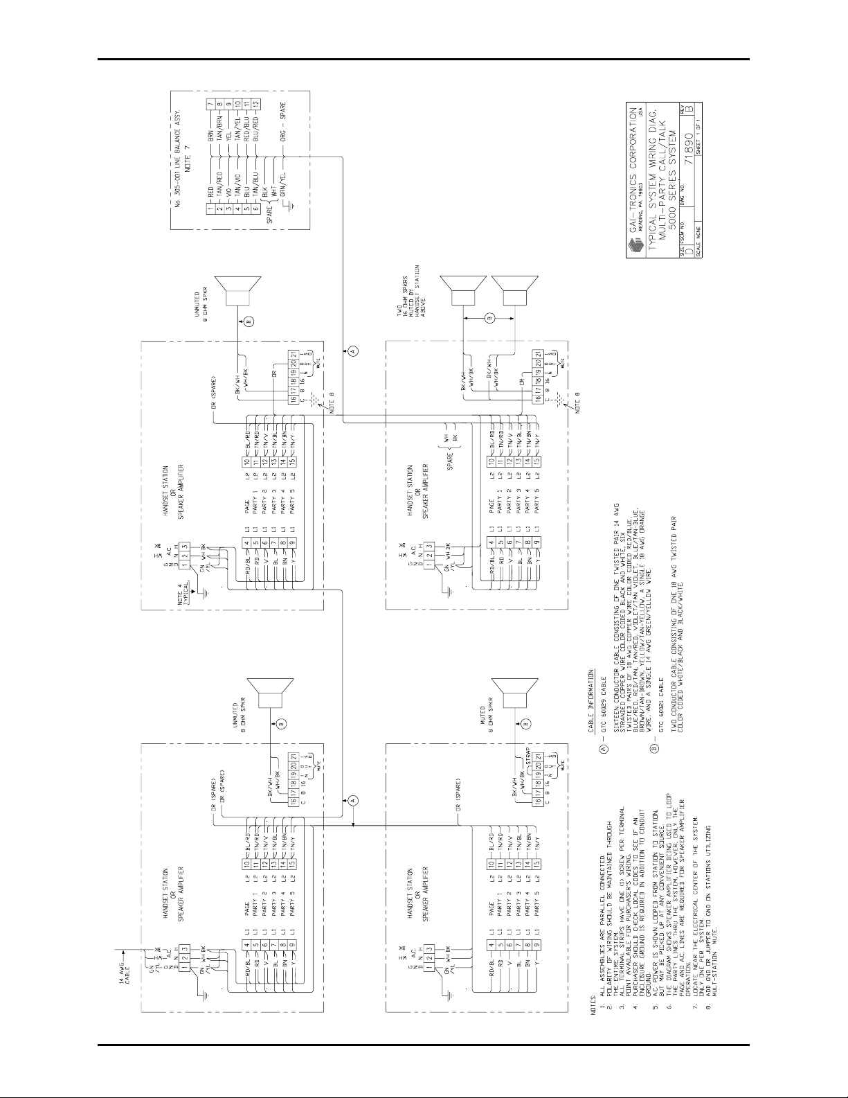
the lower s ide of an indoor wall st ation. The t erminal bloc ks of the line balance assembly and the
associated indoor wa ll sta tion must be connected by one twisted pair for the page circ uit a nd one s imilar
pair for each pa rty line. Refer to the typ i c al wiring diagrams on pa ges 8 and 9 f or the connect ions between
the Model 305 Series Line Balance Assembly and the wall station enclosure.
STEP 3 - Inter-station Conduit and Cable Installation
Genera lly, intersta tion cables are installed in cab le tra ys or conduit. To help determine the requir ed condu it
sizes, the out side diameters of the GAI-Tronics cab les discus sed in this manual a re listed in the following
table:
Cable Conductors Outside Diameter
60038-101 8 0.60 in. (15.1 mm)
60029-101 16 0.68 in. (17.2 mm)
The siz e and installation of conduit and cable must meet the requirements of a p plicable electrical codes. A
ground c onductor, wit h green/yellow insu lation, should be included with the cabl e in any area where no
conduit or non-metallic c onduit is used. Non- metallic enclosu res used with metallic conduit and c ables
without a ground conductor require a bond between the conduit(s) and the gr ound terminal (terminal 3)
withi n the encl o sure.
WARNING
No station is to be installed or operated without having a proper ground.
Where GAI-Tr onic s cab le is insta lled, each condu c tor s hould be lugged and att ached to t he t erminal. This
must be performed in accordance wit h the color code shown on the ap plicable accompanying wiring
diagr ams, or with s p ecial drawings provided for this pu rpos e.
OTE: Some cables ha ve an orange (spare) c onductor. Unless otherwise instruct ed, this c onductor should
N
be taped and not connected to the terminal strip(s) in the enclosures.
\\s_eng\gtcproddocs\standard ioms - c ur rent release\42004 instr. manuals\42004- 251a. doc
08/05
Page 3

Pub. 42004-251A
Install ation of Call/T alk Systems Page: 3 of 9
STEP 4 - Amplifier and Subset Installation
Call/Talk equipment is f actory set f or au tomatic loc al speaker muting. When the push-to-page switc h is
pres sed at a pa rticular station, the pa ging speaker connected to that sta tion is silenced, preventi ng acous tic
feedbac k to the handset micr ophone. For ca ses where t he muting featur e is not necess ary or may b e a
disadvantage, it c an be disconnected by removing the jump er between the MUTE IN and t he MUTE OUT
terminals.
Remote Muting
Additiona l amplifiers can b e muted by the paging station by c onnecting its MUTE OUT terminal to the
MUTE IN terminal of all af f ected amplifier s. This ca n be performed to avoid feedback fr om stat ions in
proximity of eac h other. A c ommon ground must be pres ent at all stations to be muted. Connect one end
of the GAI- Tr onic s orange cab le wire to the MUTE IN of one stat ion, and c onnect the other end to the
MUTE OUT of a nother stat ion. Cont inue this procedure until all stations in that area are connected. To
ensur e t hat t he s tations are correctly wired, initiate a page from a st ation, and ver ify that speaker muti ng is
occurring where desir ed.
After making any necessary muting changes, unpack and install the C01B power supply and the D01B
spea ker amplifier. The C01B and the D01B modules plu g directly int o the motherboard located in the
station enclos ure. Secure the module to the enclosure mounting br acket u sing the captive s c rews provided
with the modules. The ribbon c able from the front panel containing the handset amplifier plugs into the
mating connec tor on t he motherboa rd. The cover plate should also be p lug-connect ed t o the motherb oard
and sec urely mounted to the enclosure using the hardware pr ovided.
Step 5 - Checkout and Adjustment
All field wiring c onnections (p age line, party line(s), mute, ac power, a nd speaker) between stat ions must
be tested, and the line balance assembly installation must be complete before checkout begins . Ever y
handset should b e on- hook.
App l y the a c power, and c heck th e stati o n n ext to th e l i n e balance assemb l y . P ress th e push-to-p age s witch
(in the ha ndset handle on some stations), and s peak firmly and dir ectly into t he microphone of the handset.
The broadcast should be hea rd at all p aging speakers in the system except those associated with the s tat ion
under test. The operat or shou ld hear lit tle or no s idetone (the us er hear ing his voice fr om t he ea rpiece of
the hands et ). If the line balance as sembly is not connected prop erly, t here will be a high level of sidet one,
perhaps enough to cause feedba c k. The line balance assembly adjust s to optimize sidetone r eject ion on the
page line. I f the system is complete when the first station is c hecked, adjust the line balance as sembly as
pres ent ed in t he Line Balance Assembly Adjustment section below. Do N OT adjust the sta tion (amplif ier)
contr ols until t he line balance a ssembly is a dju sted.
Releas e t he p ush-t o- page swit c h, and c heck the party line(s ) sidetone level. Aga in, the operat or speaking
into the microphone of the handset s hould hear very litt le or none of his own voice from the earpiece in the
handset . This sidetone r eject ion will only oc c ur if the line bala nc e assembly is prop erly connected, because
it cont ains a fixed r es istor load for each p arty line. In addition, no p arty line adjustments are provided;
therefore, p arty line operation is c hecked b y c onversing bet ween two or more st ations .
\\s_eng\gtcproddocs\standard ioms - c ur rent release\42004 instr. manuals\42004- 251a. doc
08/05
Page 4

Pub. 42004-251A
Install ation of Call/T alk Systems Page: 4 of 9
Line Balance Assembly Adjustment
Remove the line balance assembly cover to ex pose the page line bala nc e control. To s et the contr ol f or
proper page circ uit loading, lift the handset fr om t he adjacent handset hook, and press the pu sh-to-page
but ton. From a normal speaking distance (approximately ½ inch), blow s teadily into the handset
microphone, and a djust the contr ol to minimize receiver sidetone. T his adjustment shou ld be made only
during the initial insta llation of a sys tem. However, if mor e than ten s peaker amplifiers are added or
deleted, rep eat the page line balance control adjustment.
After the final adjustment, r ep lace the line balance assembly’s cover, and secure it with the 4 mount i ng
scr ews to disc ourage tampering by unauthorized personnel and to pr event the entry of c ontaminants.
Handset Preamp Adjustment
The sc rewdriver-adjusted p otentiometers are located on t he p rinted circuit board mounted on t he ins i de of
the cover p late. R3 is the transmit level potent iometer and R 13 is t he receiver volume potentiometer. All
the hands et preamps a re fac tory set but may r equ ire a level adju stment due t o system loading and/or long
cab le runs. Part y- line level checks should be a ppr ox imately 0.75 V
when whistling int o a handset
RMS
microphone. Adjust the transmit level if t he volt age is not c orrect from a sta tion. R eceiver volume must be
adj usted a ccording to t h e no i se in the a rea and the preference o f the user.
Speaker Amplifier Adjustment
A namepla te on the D01B module indicates the position of the thumbwheel adjustment. The s peaker
amplifier s are factory s et f or approximately half output with a normal voice input. The outp ut must be
adjusted to s uit condit ions in the area. Ma x i mum output is 9.8 V for an 8 - ohm speaker. If maximum
outp ut is des i red, whis tle into a handset, and set the output for app roximately 9 V for an 8 - ohm speaker .
Step 6 - Troubleshooting System Problems
Hum or Buzz on the Line
A hum or b uzz on the p age circuit ( or one or mor e p arty cir c uits ) is usually due to either a short circuit of
one of the two conductors for each c ircuit to t he ground or an unb alanc ed lea kage to t he ground. As long
as the two conduc tors are t wisted pairs , and t here are no significant leakage pa ths or short c ircui ts to the
ground, any induced volta ges are the same on both conductors and do not appea r ac ross the line.
To correct the problem, locate the s ource of the grou nd. Using a n ohmmeter , check va rious junction p oints
of the system wiring t o det ermine in which direct ion the ground c an be located. By going f rom one junction
point to another and dis connecting the affect ed circuit, t he ground is loc ated. The fa ult cou ld be within a
plug-i n amplifier. However, most grounded cir c uits oc c ur du e to improper ter mina tions or are caused by
small strands protruding from an improperly lugged wire.
Another s ource of grounds or near-grounded circuits is junct ion boxes filled or partially filled with water.
In many cases, ther e are depos i ts in the b oxes, whic h when c ombined with wat er, p roduce conductive or
corrosive solu tions. These deposits c aus e lea kage between cir c uits and can c orrode the wire and terminals.
Isola tion of field wiring may be necess ary f or test purposes . If s uch isola tion removes the line balanc e
assembly from t he op erat ing portion of the system, a 33- ohm, ½-wa tt resist or shou ld be connected a c ross
®
L1 and L2 of the Pa ge/ Party
\\s_eng\gtcproddocs\standard ioms - c ur rent release\42004 instr. manuals\42004- 251a. doc
08/05
line circ uit s. These resistors must b e removed after completion of the tests.
Page 5

Pub. 42004-251A
Install ation of Call/T alk Systems Page: 5 of 9
Feedback or Distortion on the System
Eac h page and party circuit mu st be loa ded to the opt imum 33 ohms using the line balance as sembly. If the
line balance is not c onnected or is defective, the system will have excess i ve gain and will break into
feedback qu ite easily. The voice will also be dist orted, and ther e will be a high level of sidetone in the
handset receiver.
Eac h p arty line is ter mina ted with a f ixed 33-ohm r es istor in the line balance assembly. However, an
adjus tab le control is p rovided for the page line to compens ate for the number of speaker amplifiers
connected to t he s ystem. Improper adjustments will af f ect gain and will increa se the level of sidetone. See
the specif ic instr u c tions for adjusting the line balance assembly in t he S tep 5 - Checkout and Adjust ment
section.
Very Low Audio Level on One or More Lines at All Stations
It is possib l e for all or part of the syst em to f unction with a dea d short acr oss the p age or party cir c uits. If
this occ urs, the level of the sys tem will be very low, decr easing to a minimum level in the vicinity of the
short cir c uit. To locate the short ci rcuit, it is necessary t o proceed in t he s ame way as locating a ground
checking junct i on points with an ohmmeter.
Cross Talk
Cr oss talk, or inter-channel interference, is generally cau sed by the a c c ident al cr ossing of c ircuits in a
junction box. To check for this c ondition, meas ure the resistance bet ween the circuits of the interfering
channels. The resistance s hould be a very high value or infinite. Leakage or shorts to the gr ound in two or
more circ uits c an res ult in cross talk on t hose circuits.
In a mult i- party line system, it is p ossible t o have a sma ll amount of c ross talk bet ween cha nnels if the line
balance res i stor s are open or not c onnected. This condit ion c an be detected by the presence of high
sidetone in t he handset.
Static Charges
In many nor ma l insta llations , a sta tic ac voltage may b e read from the conductors of the page and party line
circ uits to the ground. In ma ny c ases, this voltage may b e as high a s 50 volts or mor e. This voltage is
induced into the circuits by capacitance to the ac power circuit (generally carried in the same cable and also
from power cab les paralleling the communication cables). This volta ge is inc onsequential and ca n be
ignored. Only when one side of the page or party circuit becomes gr ounded ar e any undesirab l e eff ects
produced.
Audio Voltage
In a p roper ly opera ting system, au dio voltage r ead across any of t he page or p arty cir c uits ( L1 to L 2) will
be 0. 5 to 0.75 volts ac on peaks when an audio signal is present such as when someone is sp eaking into a
handset. The voltage will be p roportiona l to the loudness of the person’s voice using the handset .
One Inoperative Station in a Working System
Except for a wiring error, an inoperative station indicates a defect in the amplifier at that station. This is
quickly checked by ins talling a spare a mplif ier or exc hanging amplif iers with a pr operly operating sta tion.
\\s_eng\gtcproddocs\standard ioms - c ur rent release\42004 instr. manuals\42004- 251a. doc
08/05
Page 6
Pub. 42004-251A
Install ation of Call/T alk Systems Page: 6 of 9
Safe Power Connection/Disconnection
The equipment will not c reat e arcs or s p arks, in normal operation, when completely installed and power ed.
Installing or removing an amplif ier or pl u gging in a live enclosure is not nor ma l opera tion and can cr eate
ar c s. To gua rantee saf et y, adhere to the following c aution note.
CAUTION
Do not insert or remove equipment from the live enclosures.
A bett er arrangement us es a sep arate p ower disconnect.
Connect the field wiring as detailed in the inst ructions for the same equipment.
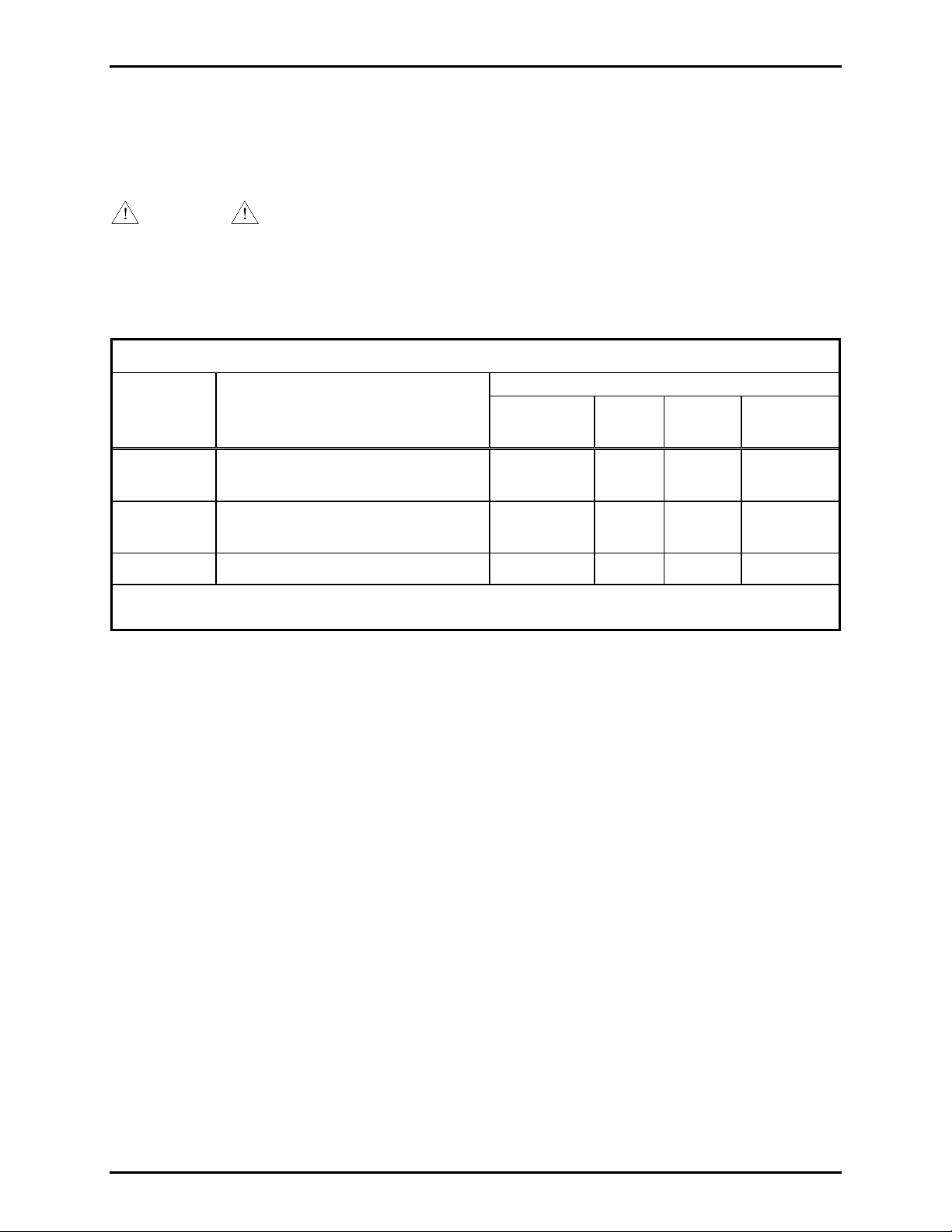
Call/Talk St atio ns
Consists of
Station
Model No.
Description
MOD5300A Indoor Single-p arty Ha ndset/ Speaker
Station
MOD5400A Indoor Multi-pa rty H andset/ Speaker
Station
MOD5500A Indoor Speaker Amplifier St ation A01B B04 C01 B D01B
Components are p ackaged s ep arately for shipment.
Enclosure
Cover
Plate
Power
Supply
Speaker
Amplifier
A01B B01B C01B D01B
A01B B02B C01B D01B
\\s_eng\gtcproddocs\standard ioms - c ur rent release\42004 instr. manuals\42004- 251a. doc
08/05
Page 7

Pub. 42004-251A
Install ation of Call/T alk Systems Page: 7 of 9
Specifications
Cover Assembly (B01B, B02B, B04)
Handset Amplifier Circuit and Handset Ass embly ( B01B, B 02B)
Output level..........................................................................................1.5 V
Output limiter................................................................................................................. 1.5 V
Frequency response................................................................................................300-6500 Hz +/-1.5 dB
Distortion................................................................................1.5% max. THD @ 1 kHz at 1.25 V output
Controls......................................................................Transmitter level, receiver volume, handset pressbar
Microphone .........................................................................................................Noise-canceling dynamic
Receiver...........................................................................High efficiency dynamic; hearing aid c ompatible
Cable.........................................................................................................Retractile, 7-foot ext ended P VC
External controls...........B02B................................................Party-line selector switch; 5 switch positions
Dimensions...................B01B, B02B .......... 7.75 W × 8.25 H × 3.75 D inches (196.9 × 209.6 × 95.3 mm)
with ha ndset
B04..................................................7.75 W × 8.25 H inches (196.9 × 209.6 mm)
Material/finish.........................................................................16-gauge cold-rolled steel/light gray enamel
Shipping weight............B01B, B02B...................................................................................4 lbs. (1.8 kg)
B04.................................................................................................2 lbs. (0.9 kg)
nominal into 3 3-ohm load
RMS
nominal
RMS
Speaker Amplifier Circuit (D01B)
Output........................................................................................12 watts minimum into 8- or 16-ohm load
Amplifier sensitivity.............................................................................................. 0.5 V ac, at rated ou tput
Frequency response................................................................................................................250-6500 Hz
Distortion............................................................................................ Less than 1% THD at 12 W, 1 kHz
Input impedance........................................................................................................ 25,000 ohms nominal
Controls..................................................................Speaker volume (adjusted by removing cover the plate)
Dimensions.............................................................................................3.75 W × 2.69 H × 2.06 D inches
Shipping weight..................................................................................................................... 1 lb. (2.2 kg)
Power Supply (C01B)
Voltage.................................................................................................................105-130 V ac, 50/60 Hz
Power consumed...........Zero/Max signal.............................................................3 W, 4 VA/30 W, 35 VA
Dimensions.................................................... 3.75 W × 2.69 H × 2.75 D inches (95.3 × 68. 3 × 69.85 mm)
Shipping weight.................................................................................................................... 2 lbs. (1.1 kg)
Enclosure (A01B)
Material/finish..................................................... 16-gauge cold-rolled steel/light gray enamel (NEMA-12)
Mounting.......................................................................................Four 0.38-inch diameter mounting holes
Connections ........................................................... Internal screw-type (single row) barrier terminal blocks
Temperature range...........................................................................................................-30° C to +70° C
Shipping weight.................................................................................................................... 6 lbs. (2.7 kg)
Dimensions...................................................... 8.75 H × 7.5 W × 3.5 D inches (222.3 × 190.9 × 88.9 mm)
\\s_eng\gtcproddocs\standard ioms - c ur rent release\42004 instr. manuals\42004- 251a. doc
08/05
Page 8
Pub. 42004-251A
Install ation of Call/T alk Systems Page: 8 of 9
\\s_eng\gtcproddocs\standard ioms - c ur rent release\42004 instr. manuals\42004- 251a. doc
08/05
Page 9

Pub. 42004-251A
Install ation of Call/T alk Systems Page: 9 of 9
\\s_eng\gtcproddocs\standard ioms - c ur rent release\42004 instr. manuals\42004- 251a. doc
08/05
Page 10

Warranty
Equipment. GAI-Tronics warrants for a period of one (1) year from the date of shipment, that any
GAI-Tronics equipment supplied hereunder shall be free of defects in material and workmanship, shall
comply with the then-current product specifications and product literature, and if applicable, shall be fit
for the purpose specified in the agreed-upon quotation or proposal document. If (a) Seller’s goods prove
to be defective in workmanship and/or material under normal and proper usage, or unfit for the purpose
specified and agreed upon, and (b) Buyer’s claim is made within the warranty period set forth above,
Buyer may return such goods to GAI-Tronics’ nearest depot repair facility, freight prepaid, at which time
they will be repaired or replaced, at Seller’s option, without charge to Buyer. Repair or replacement shall
be Buyer’s sole and exclusive remedy. The warranty period on any repaired or replacement equipment
shall be the greater of the ninety (90) day repair warranty or one (1) year from the date the original
equipment was shipped. In no event shall GAI-Tronics warranty obligations with respect to equipment
exceed 100% of the total cost of the equipment supplied hereunder. Buyer may also be entitled to the
manufacturer’s warranty on any third-party goods supplied by GAI-Tronics hereunder. The applicability
of any such third-party warranty will be determined by GAI-Tronics.
Services. Any services GAI-Tronics provides hereunder, whether directly or through subcontractors,
shall be performed in accordance with the standard of care with which such services are normally
provided in the industry. If the services fail to meet the applicable industry standard, GAI-Tronics will
re-perform such services at no cost to buyer to correct said deficiency to Company's satisfaction provided
any and all issues are identified prior to the demobilization of the Contractor’s personnel from the work
site. Re-performance of services shall be Buyer’s sole and exclusive remedy, and in no event shall GAITronics warranty obligations with respect to services exceed 100% of the total cost of the services
provided hereunder.
Warranty Periods. Every claim by Buyer alleging a defect in the goods and/or services provided
hereunder shall be deemed waived unless such claim is made in writing within the applicable warranty
periods as set forth above. Provided, however, that if the defect complained of is latent and not
discoverable within the above warranty periods, every claim arising on account of such latent defect shall
be deemed waived unless it is made in writing within a reasonable time after such latent defect is or
should have been discovered by Buyer.
Limitations / Exclusions. The warranties herein shall not apply to, and GAI-Tronics shall not be
responsible for, any damage to the goods or failure of the services supplied hereunder, to the extent
caused by Buyer’s neglect, failure to follow operational and maintenance procedures provided with the
equipment, or the use of technicians not specifically authorized by GAI-Tronics to maintain or service the
equipment. THE WARRANTIES AND REMEDIES CONTAINED HEREIN ARE IN LIEU OF AND
EXCLUDE ALL OTHER WARRANTIES AND REMEDIES, WHETHER EXPRESS OR IMPLIED BY
OPERATION OF LAW OR OTHERWISE, INCLUDING ANY WARRANTIES OF
MERCHANTABILITY OR FITNESS FOR A PARTICULAR PURPOSE.
Return Policy
If the equipment requires service, contact your Regional Service Center for a return authorization number
(RA#). Equipment should be shipped prepaid to GAI-Tronics with a return authorization number and a
purchase order number. If the equipment is under warranty, repairs or a replacement will be made in
accordance with the warranty policy set forth above. Please include a written explanation of all defects to
assist our technicians in their troubleshooting efforts.
Call 800-492-1212 (inside the USA) or 610-777-1374 (outside the USA) for help identifying the
Regional Service Center closest to you.
(Rev. 10/06)
 Loading...