

Page 1
Pub. 42004-417A
GAI-TRONICS® CORPORATION
A HUBBELL COMPANY
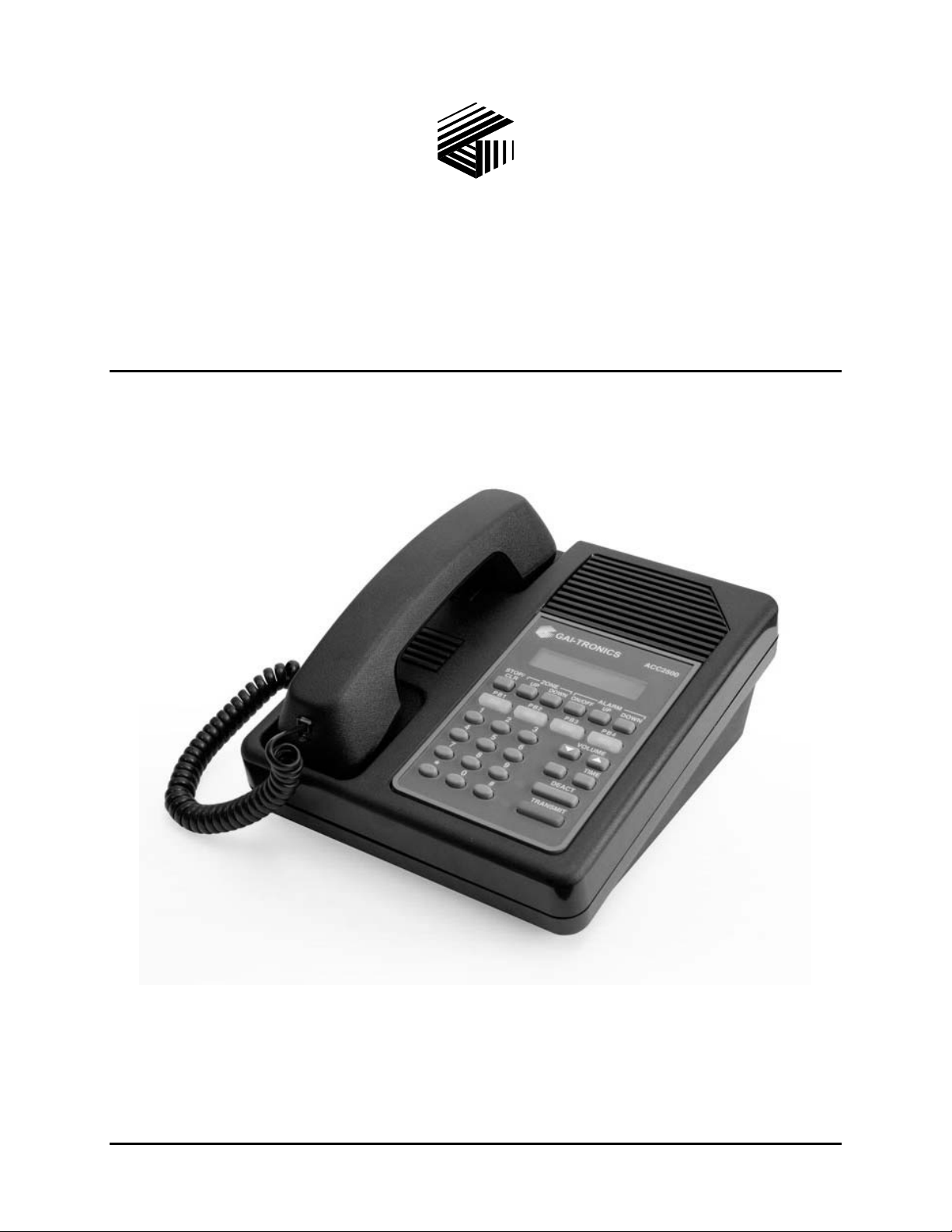
Model ACC2500 Audi o Control Center
User and Instal lation Manual
GAI-T r onics Corporation 400 E. Wyomissing Ave. Mohnton, P A 19540 US A
610-777-1374 800-492-1212 Fax : 610-796-5954
ISIT WWW.GAI-TRONICS.COM FOR PRODUCT LITERATURE AND MANUALS
V
Page 2

CONFIDENTIALITY NOTIC E
This manual is provided s olely as an operational, installation, and maint enance guide and contains sensitive
bus ines s and technic al infor ma tion that is confident i al and p ropr ietar y to GAI-Tronics . GAI-Tronics
retains a ll intellectua l property a nd other ri ghts in or to the infor ma tion contained herein, a nd such
informa tion may only be used in connection with the opera tion of your GAI-Tronics product or system.
This ma nual may not be disclos ed in any form, in whole or in pa rt, directly or indirectly, to a ny third p art y.
COMPUTER SOFTWARE COPYRIGH T S
This produc t contains cop yrighted compu ter programs stored in semiconductor memory. These progra ms
ar e c opyright ed b y G AI - Tronic s Cor poration and may not be r eproduc ed in any form without exp ress
writ ten permiss i on f rom GAI-Tronics.
WARRANTY
GAI-Tronics warrants for a period of one (1) year from the date of shipment, that any GAI-Tronics equipment supplied
hereunder shall be free of defects in material and workmanship, shall comply with the then-current product specifications and
product literature, and if applicable, shall be fit for the purpose specified in the agreed-upon quotation or proposal document. If
(a) Seller’s goods prove to be de f ecti ve in w orkma nship an d/or mate rial under normal and proper usage, or unfit for the
purpose specified and agreed upon, and (b) Buyer’s claim is made within the warranty period set forth above, Buyer may return
such goods to G AI-Tronics’ nearest depot rep air facility, freight prepaid, at which time they will be repaired or replaced, at
Seller’s option, without charge to Buyer. Repair or replacement shall be Buyer’s sole and exclusive remedy, and the warranty
period on any repaired or replacement equipment shall be one (1) year from the date the original equipment was shipped. In no
event shall GAI-Tronics’ warranty obligations with respect to equipment exceed 100% of the total cost of the equipment
supplied hereunder. The applicability of any such third-party warranty will be determined solely by GAI-Tronics.
Services. Any services GAI-Tronics provides hereunder, whether directly or through subcontractors, shall be performed in
accordance with the standard of care with which such services are normally provided in the industry. If the services fail to meet
the applicable industry standard, GAI-Tronics will, for a period of one (1) year from the date of completion, re-perform such
services at no cost to the Buyer. Re-performance of services shall be Buyer’s sole and exclusive remedy, and in no event shall
GAI-Tronics’ warranty obligations with respect to services exceed 100% of the total cost of services provided hereunder.
Limita ti ons/Exclusions. The warranty on any equipment supplied hereunder is subject to Customer’s use in compliance
with applicable FCC regulations and manufacturer specifications. The warranties herein shall not apply to, and GAI-Tronics
shall not be responsible for , an y damage to th e goods or fai lur e of the service s supplied here under, t o the extent caused by
accident, misuse, abuse, neglect, system design, product modification, failure to follow instructions contained in the product
manual, repair, or attempted repair by anyone not authorized by GAI-Tronics, improper installation, installation of parts that do
not conform to the quality or specifications of the original parts or accessories, damage or loss occurred during shipment, or any
unit which is not new when sold or upon which the serial number has been defaced, modified or removed. The warranty does
not extend to damage incurred by natural causes including Force Majeure. The warranty does not cover microprocessors if
failure is due to static damage or application of improper voltage.
THE WARRANTIES AND REMEDIES
CONTAINED HEREIN ARE IN LIE U OF AND EXCLUDE ALL OTHER WARRANTIES AND REMEDIE S,
WHETHER EXPRESS OR IMPLIED BY OPERATION OF LAW OR OTHERWISE, INCLUDING ANY
WARRANTIES OF MERCHANTABILITY OR FITNESS FOR A PARTICULAR PURPOSE.
Operational and Maintenance Procedures
modification of the equipment provided hereunder, or use of unqualified maintenance or service technicians will severely
impair the operational effectiveness of the entire communication system. Buyer hereby agrees to indemnify, defend and hold
GAI-Tronics harmless from and against any and all third party claims arising, in any manner, out of: (a) Buyer’s neglect of the
equipment; (b) Buyer’s use of technicians not authorized by GAI-Tronics to service the equipment; or (c) Buyer’s improper use
or modification of the equipment or failure to follow the operational and maintenance procedures provided with the equipment.
. Buyer acknowledges that any improper use, maintenance, or
Limitation of Liability /Damages. In no event (even should circumstances cause the exclusive warranties and remedies
set forth in the Warranty section to fail of their essential purpose) shall either party be liable for any indirect, incidental, special
or consequential damages (including, but not limited to, loss of use, loss of anticipated profits, or damages arising from delay)
whether such claims are alleged to have arisen out of breach of warranty, breach of contract, strict or absolute liability in tort,
or other act, error or om iss ion, or from any other cause w hatsoever, or any combi nation of t he foregoing.
09/08 Pub. 42004-417A ii
Page 3

Table of Contents
FOREWORD.......................................................................................................................................................1
SCOPE OF MANUAL..............................................................................................................................................1
NOMENCLATURE................................................................................................................................................. 1
ORDERING REPLACEMENT PARTS......................................................................................................................... 1
SERVICE AND REPAIR .......................................................................................................................................... 1
FCC INTERFERENCE WARNING............................................................................................................................1
SAFE HANDLING OF CMOS INTEGRATED CIRCUIT DEVICES ..................................................................................2
DESCRIPTION.................................................................................................................... ................................ 3
FEATURES AND BENEFITS ....................................................................................................................................3
INTRODUCTION TO THE ACC2500 AUDIO CONTROL CENTER ................................................................................4
SYSTEM COMPONENT REFERENCES...................................................................................................................... 4
DESK SET BUTTON PANEL ...................................................................................................................................5
INTERNAL MICROPHONE AND SPEAKER ................................................................................................................6
HANDSET............................................................................................................................................................ 6
CONNECTORS......................................................................................................................................................7
Power Connector........................................................................................................................................... 7
AMI Connections ........................................................................................................................................... 7
ACCESSORIES, AND OPTIONS A ND KITS ................................................................................................................ 9
PERFORMANCE SPECIFICATIONS......................................................................................................................... 10
OPERATION..................................................................................................................................................... 11
DISPLAY ............................................................................................................................... ............................ 11
IDLE MODE....................................................................................................................................................... 12
ZONE SELECTION ..............................................................................................................................................12
INITIATING LIVE VOICE BROADCASTS WITHOUT AN ALARM ................................................................................13
Handset Transmit ........................................................................................................................................ 14
Transmit from Internal (Local) Microphone................................................................................................. 14
Transmit from Desk Microphone or Footswitch ........................................................................................... 14
ALARM SELECTION ........................................................................................................................................... 15
INITIATING ALARM BROADCASTS WITHOUT VOICE ............................................................................................. 16
STOPPING THE BROA DCAST OF AN ALARM.......................................................................................................... 17
STOP/CLR VS. DEACT.................................................................................................................................... 17
INITIATING LIVE VOICE BROADCAST DURING A N ALARM BROADCAST .................................................................18
OVERDIALING DTMF........................................................................................................................................ 18
PROGRAMMABLE BUTTONS................................................................................................................................19
VOLUME UP AND VOLUME DOWN BUTTONS ................................................................................................. 19
COMBINATION BUTTON OPERATION................................................................................................................... 20
TIME BUTTON .................................................................................................................................................20
INSTALLATION............................................................................................................................................... 21
PLANNING THE INSTALLATION ........................................................................................................................... 21
Mounting..................................................................................................................................................... 22
FCC Interference Warnings......................................................................................................................... 22
Electrostatic Discharge (ESD) Protection.................................................................................................... 22
Cable Installation Safety Considerations....................................................................................... .............. 23
POWER CONNECTION ........................................................................................................................................ 23
AUDIO AND DATA CONNECTION ........................................................................................................................ 23
MICROPHONE SENSITIVITY ADJUSTMENTS ......................................................................................................... 24
Internal Microphone Sensitivity................................................................................................................... 24
Handset Microphone Sensitivity...................................................................................................................24
LEVEL ADJUSTMENTS AND DIAGNOSTICS ........................................................................................................... 25
Programming Menu..................................................................................................................................... 25
09/08 Pub. 42004-417A
iii
Page 4

Table of Content s ACC2500 Audio Control Center
Reloading Factory Defaults.........................................................................................................................25
Main Diagnostics Selection ......................................................................................................................... 26
PB1 – Line Output Adjust............................................................................................................................ 26
PB2 - Line-In Sensitivity.............................................................................................................................. 27
PB3 – Internal Diagnostics.......................................................................................................................... 28
PB1 – Relay Module Diagnostics..............................................................................................................................28
PB2 – Toggle Backup Mode......................................................................................................................................28
PB3 – RS-232 Diagnostic..........................................................................................................................................28
PB4 – Keyboard Diagnostic......................................................................................................................................29
PB4 – Tone/Alarm Diagnostics.................................................................................................................... 29
PB1 – Sidetone Level Adjust Mode...........................................................................................................................29
PB2 – DTMF Level Adjust Mode.............................................................................................................................30
PB3 –AMI Message Diagnostics...............................................................................................................................30
Time Setting.................................................................................................................................................30
THEORY OF OPERATION............................................................................................................................. 31
GENERAL DESK SET OVERVIEW ......................................................................................................................... 31
RECEIVE AUDIO ................................................................................................................................................ 31
SPEAKER AUDIO................................................................................................................................................ 31
TRANSMIT AUDIO ............................................................................................................................................. 32
MICROPHONE AUDIO............................................................................................................................... .......... 32
RELAY CONTROL MODULE................................................................................................................................32
RESET CIRCUIT ................................................................................................................................................. 32
CARD SUITE PROGRAMM ING SOFTWARE .............................................................................................. 33
GENERAL DESCRIPTION..................................................................................................................................... 33
CONNECTION.................................................................................................................................................... 33
INSTALLATION.................................................................................................................................................. 33
READING THE UNIT ...........................................................................................................................................33
CARD SUITE PROGRAMMING............................................................................................................................ 34
Editing Screen............................................................................................................................................. 34
PROGRAMMI NG THE ACC2500.......................................................................................................................... 34
Zone Field Name......................................................................................................................................... 34
Alarm Field Name ....................................................................................................................................... 34
DTMF Setup................................................................................................................................................ 34
Page PTT Pretime..................................................................................................................................................... 34
Zone Address Length................................................................................................................................................35
Preamble Digits........................................................................................................................................................ 35
Zone Activation Duration..........................................................................................................................................35
DTMF Digit Time ....................................................................................................................................................35
Restrict Entry of Manual Zones.................................................................................................................................35
Restrict DTMF Over Dial.........................................................................................................................................35
Preprogrammed Zone/Alarm Aliases...........................................................................................................35
Preprogrammed Zone / No Alarm..............................................................................................................................35
Preprogrammed Zone with Alarm.............................................................................................................................36
Programmable Buttons................................................................................................................................ 36
Other Necessary Programming Settings....................................................................................................... 36
TROUBLESHOOTING..................................................................................................................................... 37
TROUBLESHOOTING THE ACC2500 DESK SET ....................................................................................................37
FUSE REPLACEMENT.......................................................................................................................................... 38
CIRCUIT BOARDS...........................................................................................................................................39
SCHEMATICS...................................................................................................................................................43
NOTES............................................................................................................................................................... 52
09/08 Pub. 42004-417A iv
Page 5

Foreword
Scope of Manual
This manual offers descriptive data and service information for the Model ACC2500 Audio Control
Center . Ser vice diagra ms and pr inted circu it board deta ils ar e a part of t his service ma nu al.
Nomenclature
The mo del number, loca ted on the na meplate on the bottom, sp ecificall y identi fies GAI-Tr o n i cs equipment.
If a dditional options a re order ed, the opt ion is identified on the circuit board.
Ordering Replacement Parts
When ordering replacement parts or requ esti n g eq uipment inf o rmation, please i n clude the complete
identification number. T his app lies to all c omponent s, kits, a nd c hassis. If the component pa rt nu mber is
not known, the order should inclu de t he nu mber of the chassis or kit of whic h it is a part and suffic ient
descri ption of t he desired component to identify it. Order parts from:
Customer Service
GAI-Tronics Corpora tion
400 E. Wyomissing Ave.
Mohnton, PA 19540
US: 800-492-1212
Outside US: 610-777-1374
Service and Repair
Inoperative or ma lf unctioning equip ment s hould be returned to the fact ory for repair. Please call
1-800-492-1212 to obtain a R et urn Authorization number, published r ep air p rices, and shipping
instruct ions. A R et urn Au thorization number can also be ob tained by visiting our website at
www.gai-tronics.com.
OTE: A purchase order or credit card number is r equ ired pr ior to process ing non- warranty repairs.
N
FCC Interference Warning
The F CC r equ ires that manuals pertaining to Class A and C lass B c omp uting devices mus t contain
war nings about pos sible interference with local res idential r adio and TV reception. T his warning reads as
follows:
NOTE: This equipment has been tested and found to comply with the limits for a Class A digital device, pursuant to Part 15 of
the FCC Rules. These limits are designed to provide reasonable protection against harmful interference when the equipment is
operated in a commercial environment. This equipment generates, uses, and can radiate radio frequency energy and, if not
installed and used in accordance with the instruction manual, may cause harmful interference to radio communications.
Operation of this equipment in a residential area is likely to cause harmful interference in which case the user will be required
to correct the interference at his own expense.
1 09/08
Page 6

Foreword ACC2500 Audio Control Center
Safe Handling of CMOS Integrated Circuit Devices
Many of the integrated cir c uit devices used in communicati ons equipment are of the Complementary M et al
Oxide Semicondu c tor (CMOS) type. Becau se of their high open circuit impedanc e, CMO S integrated
circ uits are vulnerable t o damage fr om s tatic char ges . Ca re must be taken handling, shipping, and
servicing them and the as semblies in which they are used.
Even though protection devices are pr ovided in C MOS integrated circuit inputs, the protection is effective
only aga inst over- voltage in the hu ndreds of volt s ra nge such a s is encount ered in an operating system. I n a
system, cir cuit elements dis tri bute st at i c charges an d load the C MOS circui ts, decreasing the chance of
damage. However, CMOS circ uits c an be damaged by improp er handling of the modules, even in a
system.
To avoid damage to c i rcuits, ob serve the following handling, shipping, and servic ing precautions :
1. Pr ior to a nd while servicing a circuit module, particu larly after moving within the service a rea,
momentarily t ouch both hands to a ba re metal, earth- grounded su rfa c e. This will discharge any st atic
charge that may have accumulated on the person doing the s ervicing.
OTE: Wearing a c onductive wris t strap will minimize static b uild-up du ring ser vic ing.
N
2. Whenever possible, avoid touc hing any electr ic ally conductive parts of the circuit module with you r
hands.
3. Power down the unit bef ore installing or removing the circu i t module.
4. When servicing a cir c uit module, avoid carpeted areas, dry environments, and cer tain t ypes of clot hing
(silk, nylon, etc. ) because they contr ibute to sta tic build- u p. S imila rly, disconnect the t es t probe prior
to removing the ground lead.
5. All electric ally power ed t es t equipment s hould be grou nded. Apply the ground lea d f rom the test
equipment to the circuit module before connecting t he t es t pr ob e.
6. If a c i rcuit module is removed from the sys tem, it is desi rab le t o lay it on a c onductive su rfac e ( such a s
a sheet of aluminum foil) that is connected to ground through 100k of resistance.
7. When soldering, be sure the solder ing iron is grounded and has a grounded tip.
8. Pr ior to connecting jumpers , repl acing cir c uit components, or touching C MOS p i ns (if this becomes
necessa ry in the r ep lacement of an integrated circuit device), b e sure t o discharge any st atic build-up as
descri bed in procedu re 1. Since volta ge differences can exist across the huma n body, it is
recommended that only one hand be used if it is necess ary to touch pins on the C MOS device and
associated board wiring.
9. When replacing a CMOS integrated circuit device, lea ve t he device in its conductive rail c ontainer or
conduct ive foam until it is to be inserted into the printed circuit module.
10. All low impedanc e t est equipment ( such a s pulse generat ors, etc.) should be connected to CM O S device
input s aft er power is applied t o the CMOS circ u i try. Similarly, suc h low impeda nc e equip ment should
be disconnected before p ower is turned off.
11. Rep lacement modules shipped separat ely f rom the factory will be p ackaged in a c onductive mat erial.
Any modules being trans port ed from one ar ea to another should be wrapped in a similar ma teria l
(alu minum foil may be u sed). Never us e non- conductive mat erial for packaging these modules.
09/08 2
Page 7

Description
Features and Benefits
Feature Benefit
LCD display Allows us er-fr iendly int erfac e; displays zone and alar m, sta tus and
diagnostic infor ma tion.
Pr ogrammab le b uttons Four buttons p rovide up to eight us er-defined actions, i.e.,
prep rogrammed zone and alarm selection, button r ema p ping, ou tput
contr ol, etc.
DTMF Control for Model 133x2
Series Amplified Addressa b l e
Speakers and GAI-Tronics SBA
and SBM Stanchion assemblies.
Hot-Sta ndby Control Additiona l units can be connect ed for hot standb y c ontrol in case of
External Event Notification LCD indicates external Audio Messenger Interface (AMI) event activity
Direc t AMI Au dio Monitori ng User c an hear all a udio being genera ted by the AMI whether originat ed
Live Broadcast Supports live broadcast with zone selection
Fr ont-mounted controls and
adjustments
Pr eannounce tone When pr ogrammed in the Audio M es senger Int erfac e ( AM I), a
Built- in interna l mic and speaker Allows for single push-button communication.
Genera tes the necess ary c ontrol t ones to addr ess the GAI-Tronics
Amplified Addressabl e Speaker series and St anchion Br oadcast
products.
prima ry failure. ( Requires relay control option to be installed.)
such as cont act c losur e or phone call.
from the ACC2500 or external event such as a timed event or telephone
broadcast.
Includes mute/unmut e and local speaker on/off.
preannounce tone will be generated prior t o live b roadcast f rom the unit
spea ker and all addr es sed speakers/sta nc hions.
Pr ogrammab le inputs and outputs Inputs a nd outpu ts ca n be configured for a var iety of selections.
(Requires relay contr ol option to b e ins talled.)
3 09/08
Page 8

Description ACC2500 Audio Control Center
Introduction to the ACC2500 Audio Control Center
The ACC2500 Audio Control Center works in conjunction with the GAI-Tronics Audio Messenger
Interface (AMI), Model 133x2 Addressable Amplified Speakers, and the GAI-Tronics Stanchion Broadcast
products to provide a complete wide-a rea broadc ast and alert system. T he u nit allows addressing of
individual, zone or all addr es sable u nits in the system. Using the Audio Messenger Int erfac e, live voice,
prep rogrammed voice/tone messages as well as telephone dial-up live b roadcast s can b e ma de over the
system.
Eac h of the four programmable b uttons can b e conf igured for up t o eight preset zone selection or pr eset
zone/alarm select ion. In addition, t he fou r optional inputs and three outputs can be programmed for
var i ou s uses. With optional relays , outputs c an be configu red for O n- Air Light, General Purpose C ontrol,
and On/Off. Inputs can be configu red for Button Remap, Outp ut Link, and L ink to a p reprogrammed zone
and a larm conf igu ration.
The ACC2500 uses DTMF control for zone selection of the Addressable Amplified Speakers or Stanchion
Broadcas t pr oducts. The u nit allows direct entry of zones via the numer ic keyp ad or s election of zones
using a prep rogrammed alias (programmed using the C ARD Su ite software a pplica tion.)
In addition, the u nit allows direct entry of preprogrammed alarm messages/t ones using the numer ic keyp ad
or selection using t he names of each message/alarm a s programmed using the AMI AC T tool p rovided with
the Audio Messenger Interface. Upon power-up, the ACC2500 will verify the contents of the AMI
messages and ret rieve them for use as neces sar y.
System Component References
The following repres ents a few common system component references.
ACC2500 Audio Control Center – The ACC2500 is a desktop unit complete with push-to-talk handset,
integral speaker and microphone, LCD dis play, D TMF keypad, and various c ontrol buttons. This unit
communicates directly with the AMI via RS-232.
Audio Messenger Interface (AMI) – The AMI provides p rogrammed speech messa ge and alarm tone
outputs via activation from the ACC2500. Additionally, the AMI provides dial-up telephone access to the
system.
Stanchion Broadcast Products – T he 234SBA Stanchion Broadcast Assembly and 234SBM Stanchion
Broadcast Module receive the audio signal generated by the AMI and/or ACC2500. The units’ integral
spea kers broadcast the received signa l.
Addressable Amplified Speaker – The Addressable Amplif ied Speaker series p rovides disc rete sp eaker
broadcasts of the AMI or ACC2500 audio signal.
09/08 4
Page 9
ACC2500 Audio Control Center Description
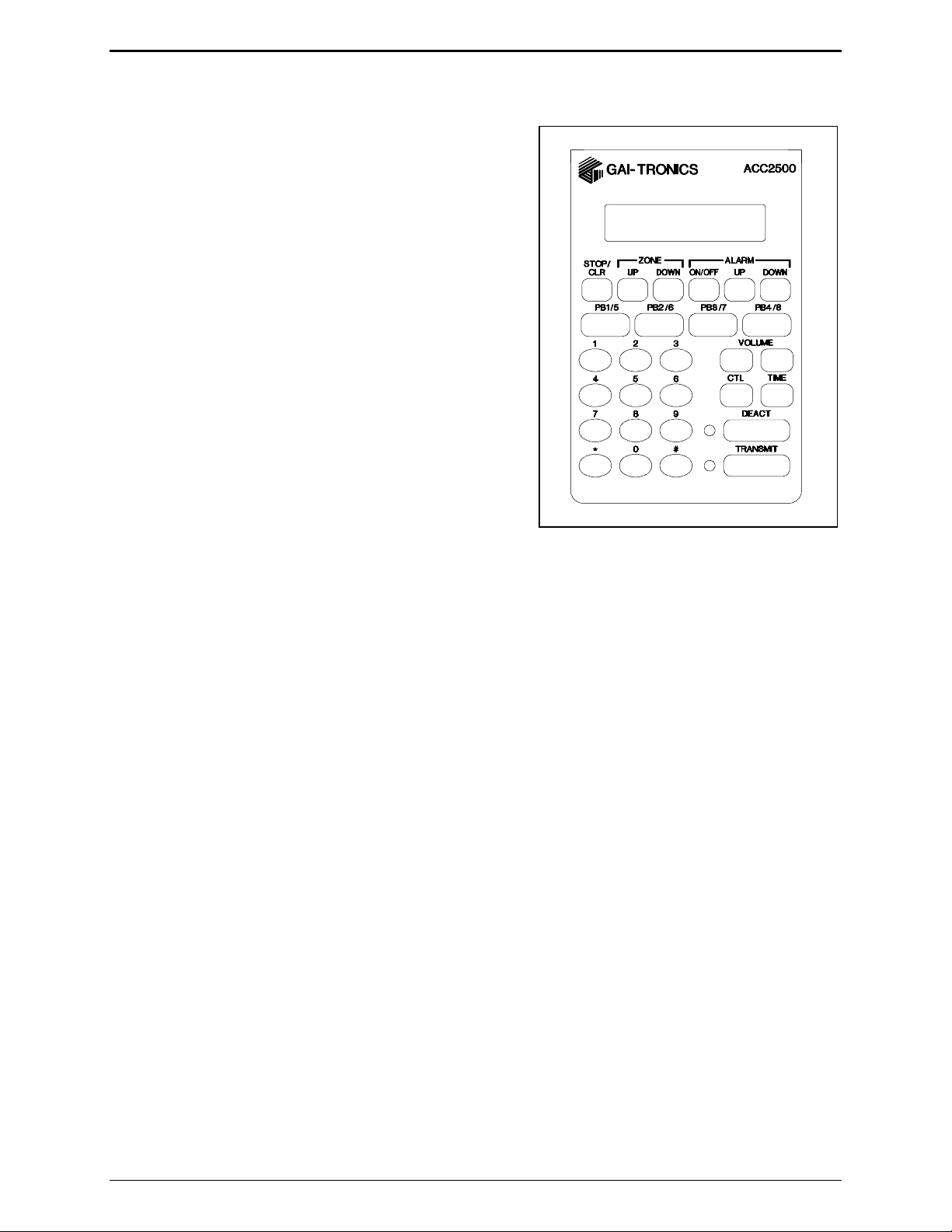
Desk Set Button Panel
TRANSMIT Button and LED The red TRANSMIT button is
used to place the unit in the broadcast mode and to initiate
voice and a l arm trans missions. The
locat ed t o the left of the b u tton, illuminates s teadily when
tr ansmitt ing voice and flashes when the AM I is actively
generat i ng a message/ alarm or in a telephone voice call.
DEACT Button and LED The DEACT button is used to
immediately deact ivate a ll active s peakers or br oadca st
assemblies and cease any activity cur rently on the AM I.
VOLUME Buttons The units c ontain t wo b uttons labeled
VOLUME imprinted with up and down arrows. They are
used to inc reas e and decrease the local speaker volume and
microphone levels. They ar e also us ed for special
applications.
CTL CTL is used in conjunction wit h other bu ttons to
provide secondar y key f unctions .
TRANSMIT LED,
TIME The TIME but ton briefl y displays the current time.
This time is retrieved from the AMI and ca n b e u seful to
ACC2500 Front Panel
monitor for timed events automatically generated by the AMI.
Keypad Buttons The numeric keypad is us ed f or the select ion of a desir ed zone and alarms. See the
Oper ations section of t his manua l for fu rther inf ormation.
STOP/CLR Bu tton The STOP/CLR butt on serves t wo p urposes. While an ala rm is being generated
pressing the
STOP/CLR button will stop the generation of the ala rm and keep the addressed
spea kers/broa dc ast assemblies active for their time-out duration. When selecting a zone or alarm, pressing
STOP/CLR button will, if allowed via CARD Suite, per mit ma nual entry of the zone or alarm.
the
ZONE UP and DOWN Buttons: The ZONE UP and DOWN bu ttons allow selection of a pa rticular addres s
or zone using prep rogrammed aliases . If no a liases have been programmed using t he C ARD Su ite
applicat ion, these buttons ar e not used.
ALARM ON/OFF Button The ALARM ON/OFF button is used to t urn a l arm generation on or of f. When
off, pressing the
holding the
display. Pressing the
TRANSMIT but ton will allow voice-over live b roadcast while keeping t he alar m pl aying at a reduc ed or
TRANSMIT but ton will act ivate the s elect ed zone a nd allow live voice broadcast while
TRANSMIT but ton. When on, the ala rm will be displa yed in t he s econd line of the LCD
TRANSMIT but ton will initiate the alarm. While the al arm is active, p ressing t he
muted level.
ALARM UP and DOWN Buttons The ALARM UP/DOWN buttons allow selection of t he mess ages as
programmed in the AMI via the AC T tool p rogram.
5 09/08
Page 10
Description ACC2500 Audio Control Center
LCD Display: Each of the desk sets includes a backlit 2×16 charact er LCD display f or operator
information.
Programmable Buttons: The PB1, PB2, PB3, and PB4 pr ogrammab l e b uttons can ea c h be configured to
perform two separate func tions: one directly and t he ot her in conjunction with the
CTL button. D ep ending
on its conf igura tion, the s elect ed b utton illu mina tes when it is p ressed.
Internal Microphone and Speaker
This microphone is int ended for use in low nois e environments. The hands et must be on-hook in order t o
use t he microphone. The internal microphone and sp eaker a re pr ovided t o allow one-bu tton
communication.
Handset
Each ACC2500 is equipped with a handset with a coil cord used for receiving and transmitting calls. The
handset includes a push-to-talk (PTT) pressb ar.
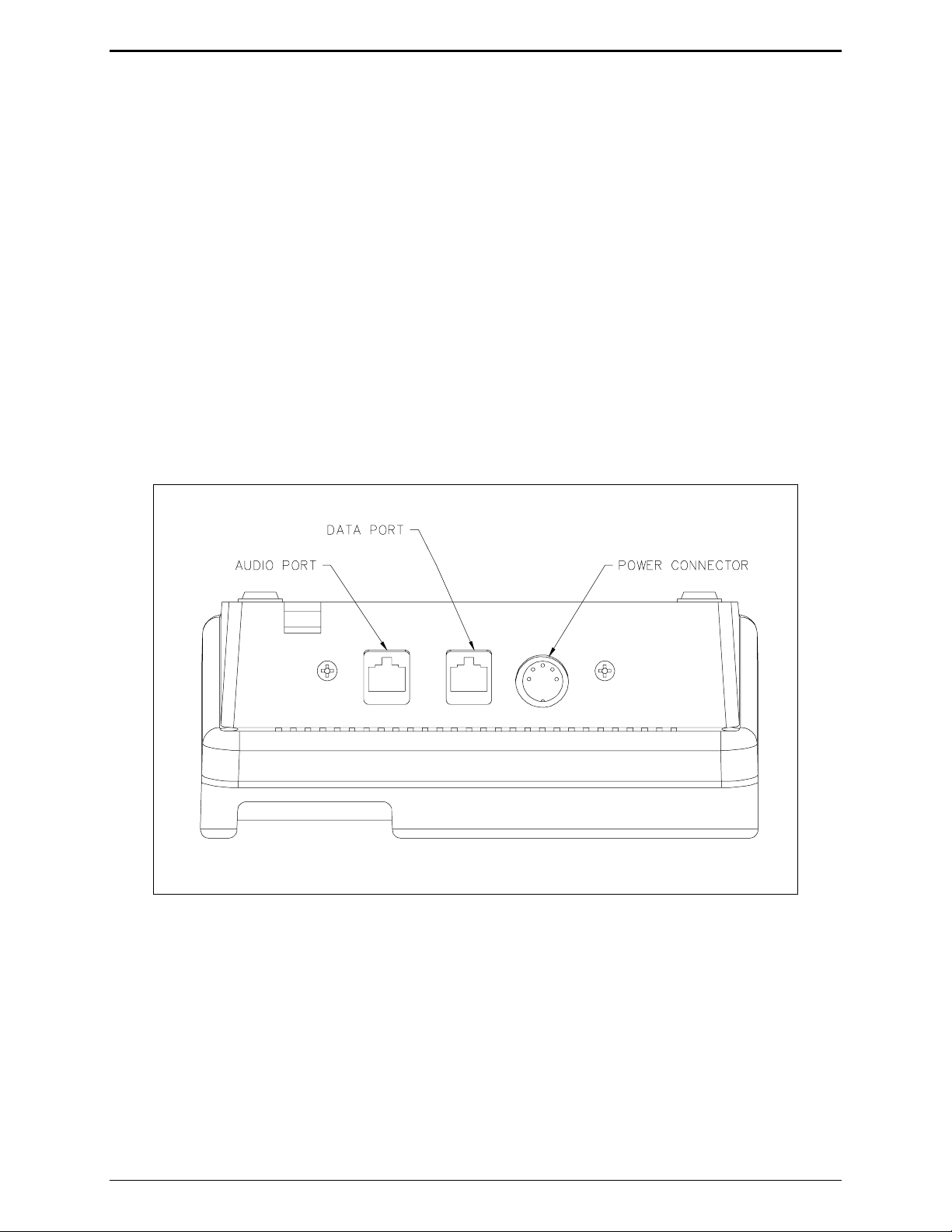
Rear View of ACC2500
09/08 6
Page 11
ACC2500 Audio Control Center Description
Connectors
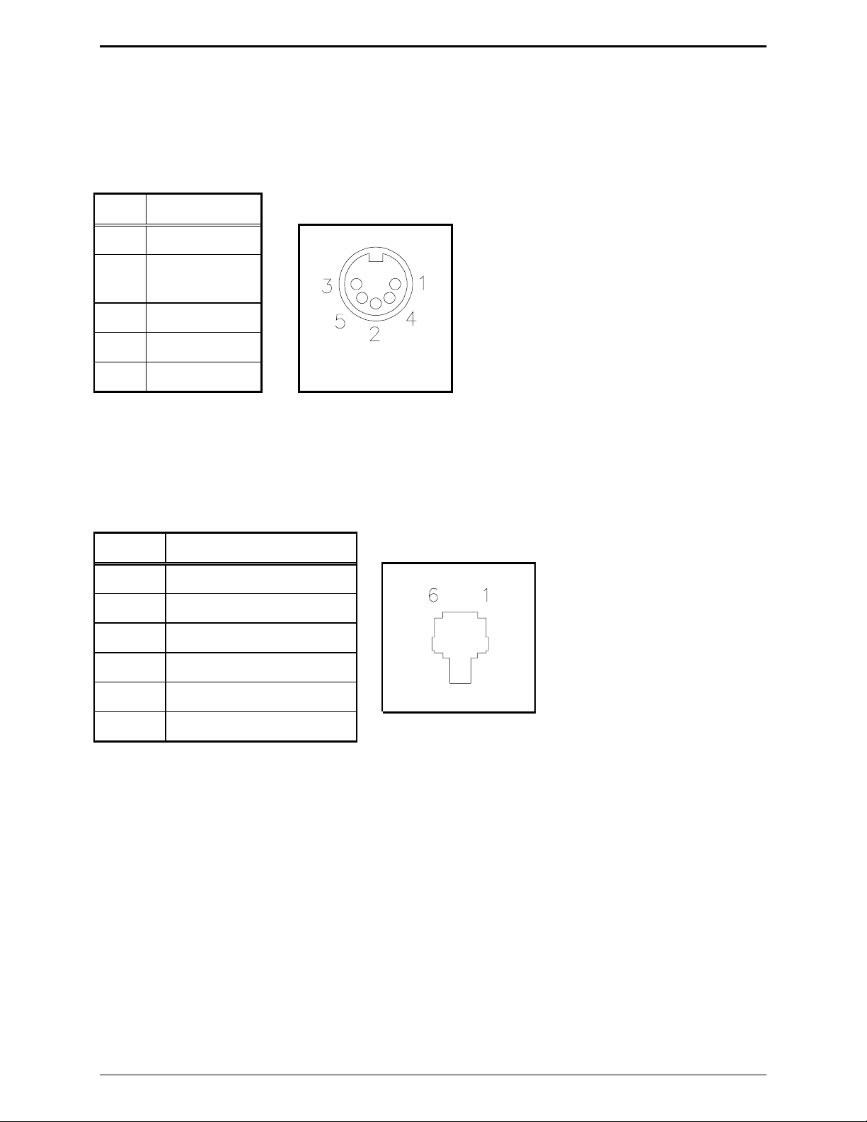
Power Connector
The ACC2500 is powered by a listed ac wall transformer supplying nominal 12 V dc. The operating range
is 10 .5 t o 15 V dc. The 5-p i n power connect or diagram a nd pinout are s hown below:
Pin Function
1 -IN
2 Battery backup
+IN
3 +IN
4 -IN
5 +IN
AMI Connections
The rear of the ACC2500 contains two modular ports used to connect to the f ront control port of the AMI.
The 6- pin line connector is the transmit and receive audio connection t o the AMI.
Pin Function
1 No connection
2 RX +IN
3 TX +OUT
4 TX –OUT
5 RX –IN
6 No connection
7 09/08
Page 12

Description ACC2500 Audio Control Center
The 8- pin modular c onnector is the RS-232 data control port.
Pin Function
1 No connection
2 RS-232 TX OUT
3 No connection
4 GND
5 No connection
6 No connection
7 RS-232 RX IN
8 No connection
NOTE: It is important that those pins labeled "No connection" be left un-terminated. Connection of
these pins may damage the ACC2500 or AMI and may not be covered under warranty.
To facilitate the connect ion of these two ports to the AMI, the 69612-xxx (purchased separately) contains
thr ee modula r connectors and two ca bles. The two ca bles included combine the 8-pin and 6-p in port s as
necessary to allow connection to the front AMI c ontrol port u sing a s tanda rd ca tegory-5 net working cable.
This CAT-5 cab le mus t be provided by the inst aller a nd must not exc eed 45 feet in length.
09/08 8
Page 13

ACC2500 Audio Control Center Description
Accessories, and Options and Kits
Description Part No.
CARD Suite Software on CD XAC1000A
Programming Cable XAC0004A
Relay Control Field Install Kit XRC0001A*
Mounting Kit for Option Boards XAC0100A
Power Supply, 120 V ac 60 Hz 3308-00750-00
Power Supply, 110/220 V ac 50/60 Hz 3308-00750-10
Desk Microphone** XDM002A
Gooseneck Mi c rophone** XGM002A
Amplified Headset** XHS003B
Coiled Cord (required for XHS003B) XCC004B
Footswitch** XFS002A
Audio Accessory Box XAAB002A
*Requires XAC0100A (1 per unit)
**Requires XAAB002A Audio Accessory Box (1 per unit)
9 09/08
Page 14

Description ACC2500 Audio Control Center
Performance Specifications
Color................................................................................................................................................ Black
Physical size................................................................................................ 7.6 W × 8.9 L × 4.7 H inches
Weight........................................................................................................................................... 2.4 lbs.
Temperature range...........................................................................................................-35° C to +70° C
Humidity.................................................................................................. 95% at 50° C (non-condensing)
Tx/Rx impedance.......................................................................................................... 600 ohms nominal
Power input................................................. 10.5 to 16 V dc; 500 mA maximum from supplied ac adapter
Safety............................................................................................
Class III SELV powered equipment.
Powered by UL-listed (E104603)
and CSA-certified (LR67888) Class 2 ac adapter.
Emissions:......................................................................USA: FCC Part 15, Sub. B- Verification.
Canada: ICES – 003
Line interface.............................................................................................................FCC Part 68 Exempt
(Categor y II Tariff #260 service for private/leased line applications)
Canada: IC CS03-8
Range -14 to +12 dB into 560 ohms
Frequency response..................................................................+
Hum and noise.................................................................................. Less than -45 dB below rated outputs
Audio output to speakers.................................................. 1 watt minimum with level in compression range
Audio distortion............................................................................................................Less than 3% THD
3 dB, 300 to 3000 Hz (except notch filter)
09/08 10
Page 15

Operation
The ACC2500 provides system control of a GAI-Tronics wide-area broadcast system consisting of an
Audio Messenger Int erface ( AM I), amplified addressable speakers and/or sta nc hion broa dc ast produc ts. I t
allows selection of individual units or zones and selection of preprogra mmed speech/ tone ala rms.
Audio that is outpu t from t he AM I is direct ly rout ed t o the integral speaker or handset to allow dir ect
monitoring of the AMI audio by the ACC2500 operator.
Display
The ACC2500 has a backlit 2×16-chara c ter su per-t wis t LCD display to provide va luable op erator
information. This infor mation allows the opera tor t o det ermine the sta tus of the unit. The following
describes the disp lay at var ious st ates:
At power up:
• Initia lly, line 1 shows:
• After 3 to 5 seconds, line 1 shows
CHECKING PARAMS, and line 2 shows : PLEASE WAIT.
ACC2500, and line 2 shows the firmware version.
During normal operation,
Line 1 shows the currently selected zone, i.e. Zone 12
Line 2 s hows:
• Speaker/handset audio level during a change of level
• Alar m s election when tur ned on or active
• AMI activit y during int ernal and external events
• The current time when the
TIME button is pressed
• Oper ator instr uctions during b roadcast of live voice
During installatio n, the displa y shows various diagnosti c inf ormation.
11 09/08
Page 16

Operation ACC2500 Audio Control Center
_ _ _
Idle Mode
When power is applied, the ACC2500 is in the receive or idle mode, allowing any AMI audio to be heard
through the speaker or handset. It is always in this mode unless the unit is transmitting.
The ACC2500 contains an internal or local speaker and a handset that operate as follows:
• When the hands et is in the cradle, or on-hook, audio is heard on the internal speaker. In s ome
operationa l modes, this c an be cha nged, i.e., muting the speaker by pressing CTL + VOL Down.
• When the hands et is off- hook, audio is routed to the ha ndset receiver . By us ing the front panel bu ttons,
you may optionally s elect to hear audio through the local speaker in a ddition to the handset.
Zone Selection
The system can have many zones a vailab le to the operator each including one to many speakers or
broadcast a ssemblies. I n order t o select the proper z one f or a b roadcast of any type, the oper ator must f irst
select t he desired zone. T his zone is disp layed on the fir st line of the LCD disp lay.
Note that during inst allation and programming, the zone label can be changed to a des ired display using the
CARD Suite a pplica tion. By defa ult, if nothing is programmed, the word “Z one” will b e dis played on the
first line of the dis p lay. This cou ld be changed to “Grou p,” “Area,” “Z ” or any alpha nu mer ic des c ript ion
of up to eight character s.
After initial power - up, t he dis play will be a s shown below where the address of all units and zones is
programmed to be 3 digits in length.
→
Z o n e :
The “
→” in the first location of the first line indicates that the zone selection is active. To manua lly select a
zone using the numeric key, enter the desired address or zone. To select zone 123, press “1,” “2,” followed
by “3 .” As t he digit s ar e entered, the first digit will be display in the thir d blank and moved to the left as
sub sequent digits are enter ed. If more than the allowed number of digits is entered, the zone entry will be
clear ed and the last digit will bec ome the first digit of the new address. Af ter entr y of the zone, t he dis play
will app ear a s shown below:
→
Z o n e : 1 2 3
09/08 12
Page 17

ACC2500 Audio Control Center Operation
If zone a liases have been programmed using the CARD S uite ap plicat ion, the operator may choos e a zone
using a name instead of a direct number. For example, zone 123 can be programmed as “Zone 1,” zone
234 can be “Zone 2,” zone 345 can be “Zone 3,” zone 456 can be “Zone 4” and all zones can be “Zone
All.” To select a particu lar zone, the operator can use the
ZONE Up/Down b uttons to sc roll to t he desi red
zone suc h as “ Zone 3” as shown below:
→
Z o n e : Z o n e 3
If the a lias ha s a pre-configured ala rm associat ed wit h it, the a l arm will be disp layed on the second line of
the display. The operator may not override or t urn off this pre-configu red alarm and attempting to do so
will displa y an err or messa ge along with an error tone.
If the op erat or wishes to rever t to manu al entry, pressing the
STOP/CLR button will switc h back to ma nual
entry and will display the las t manua lly ent ered zone. If the unit is p rogrammed to restrict ma nual entry of
the zone addressed, pressing the
manual entry mode, press i ng
STOP/CLR button will res ult is an error message and tone. While in
STOP/CLR a second time clears t he zone ent ry.
Initiating Live Voice Broadcasts without an Alarm
After selecting the desired zone, the op erat or may initiate a live b roadcast immediat ely b y pressing and
holding any P TT sourc e s uch as the main
accessory.
Upon pr es sing and holding P TT, if the s elect ed zone is not act i ve (mor e on this below) the u nit will
generate the necessary DTMF digits to activate the desired zone. Duri ng the DTMF generation, the second
line of the display will be:
After generation of the DT MF sequ ence, the AMI, if pr ogrammed to do so, will generate a
preannouncement tone that is broa dc ast over the unit speaker and the select ed zone. The operator will hear
the preannouncement t one and will be instructed to wait during t he generation of the tone. Upon
completion of t he p reannounc ement tone, the display will change t o:
TRANSMIT button, handset PTT or PTT of a c onnec ted
Z o n e : Z o n e 3
* * * WA I T * * *
A C T I V E : Z o n e 3
* * * T A L K N OW * * *
“ACTIVE” will b e flashing indicating that the s elect ed zone has been ac tivat ed and is within it s time-out
duration. As long as the PTT source is held, the displa y will remain in this state. T he op erator may sp eak
whenever the display i ndica tes ***TALK NOW***.
To cease voice br oadcast the operat or must release t he P TT sourc e. Upon doing so, the displa y will change
to:
A C T I V E : Z o n e 3
13 09/08
Page 18

Operation ACC2500 Audio Control Center
Where “ACTIVE ” will c ontinue to flash for a programmed duration. T his duration is det ermined by and
should be set to what the time-out time of the units in the particular zone a r e programmed to. For exa mple,
if the units of a z one are set to deacti vate af ter 5 seconds of ina c tivity, this time shou ld be set for 5 seconds .
While “ACTIVE” is displayed and flashing, the operat or may initiate another broadcast and the unit will
not regenerate the DTMF sequenc e n eed ed to a ctiv ate the uni ts i n the zone. When the word “ACT IVE” i s
not disp layed and flashing, the unit will genera te the necessary DTMF sequence to ac tivat e t he s elect ed
zone each time a broa dc ast is initiated.
Handset Transmit
Use of the handset is recommended when the desk set is located in noisy s urroundings. Pr es s the handset
PTT bar or
TRANSMIT button and speak into the handset microp hone to transmit when t he handset is off-
hook.
Transmit from Internal (Local) Microphone
Use the internal microphone only in low noise environments. T he handset must be on-hook f or the local
microphone to operate. Pres s the
TRANSMIT button and speak in the direction of the integral microp hone.
For the best t ransmit audio quality, maintain a dis tance of about 18 inches from the microp hone.
Transmit from Desk Microphone or Footswitch
All models can b e keyed to t ransmit with a n ex ternal des k microphone when used wit h the optional Model
XAAB002A Audio Accessor y Box. Use of the GAI-Tr onics Model XHS002A Desk Mic, or compatible
microphone, is r ec ommended. R efer to t he XAAB 002A documentation for connection and installation of
this op tion.
09/08 14
Page 19

ACC2500 Audio Control Center Operation
r
_ _ _
r
_
1 2
r
Alarm Selection
In addition to live voice broadcasts, the ACC2500 allows selection of programmed alarm/speech messages
to be broadcast to particu l ar zone. If the displayed alias ha s a preconfigured alarm associat ed wit h it, t he
operator ma y not change it or turn it off . To s elect an a larm, press the
DOWN but tons unt il the second line of the display is as shown b elow:
Z o n e : Z o n e 3
→
A l a
m:
The “
→” in t he first loc ation of the second line indicat es that the ala rm selection is active. To manually
select an ala rm using t he nu mer ic key, enter the desired alar m nu mber as stored in the AMI. To select
ala rm 12, p ress “1” followed by “2.” As the digits a re entered, the firs t digit will be disp lay in the third
blank and moved to the left as subsequent digits a re entered. I f more than t he allowed number of digits is
entered, the alarm entry will be cleared and the last digit will become the firs t digit of t he new alarm. Af ter
entry of the ala rm, the display will be a s shown below:
Z o n e : Z o n e 3
→
A l a
m:
ALARM ON/OFF, ALARM UP or
The a larm a liases diff er from t he zone aliases in that they are retrieved from the AMI a s necessary a nd
programming of thes e aliases is done with the ACT Tool. To select a particular alarm using the AM I
aliases, press the ALARM Up/Down buttons to scroll to the desired alarm name.
Z o n e : Z o n e 3
→
A l a
m: L o c k D o w n
Note that, like zone selection, t he name of the alarm field can be changed via CARD Suite t o any desir ed
alphanumeric name of up to eight c haracters. By defa ult, the field will be named “Alm:” A consideration
here is t hat t he AM I message names are up to 32 c haracter s in length and using the field name of “Alarm”
uses valua ble displa y spac e allowing only the fir st 9 character s of the AMI name to be displayed. If more
characters are desired, the field name can be cha nged t o “A,” which will allow up t o 14 cha racters of the
AMI name to be displayed.
If the op erat or wishes to rever t to manu al entry, pressing the
STOP/CLR button will clear the al arm entr y.
15 09/08
Page 20

Operation ACC2500 Audio Control Center
r
r
Initiating Alarm Broadcasts without Voice
After the desired zone and alarm have b een s elected, the operat or may begin b roadc ast ing the ala rm by
pres sing and releasing a ny PTT source such as the main
connected a c cessor y.
Upon pr es sing PTT, if the selected zone is not active, the unit will generate the necessary DTMF digits t o
act i vate the desired zone. Du ring the DTMF gener ation, the second line of t he dis p lay will be:
Z o n e : Z o n e 3
* * * W A I T * * *
After gener ation of the DTM F sequence, the AMI will begin genera tion of the selected alarm that will be
broadcast over the unit’s speaker and the selected zone. The display will be a s shown below:
A C T I V E : Z o n e 3
A l a
m: L o c k D o w n
TRANSMIT button, handset PTT or PTT of a
“ACTIVE,” “Ala rm” and t he a l arm name will be flashing indica ting tha t the selected zone ha s been
act i vated, is within its time-out duration, a nd the selected alarm is b eing b roadc ast. In addition, t he
TRANSMIT LED will f lash. As long as the alar m is being broadcast the display will remain in t his state.
Depending on the programming of the pa rticu l ar alarm selected in the AMI , the a larm may b roadc ast one
or more t imes or repeat indefinit ely.
If the alarm is programmed to broadcast for a predeter mined number of times, upon completion of the las t
broadcast, the ala rm will cease pl aybac k and the flashing of “Alarm, ”and the alar m name and the
TRANSMIT LED will cease. Aft er the selected units time out due t o inactivit y, the display will retu rn to
the alarm edit mode as shown below:
Z o n e : Z o n e 3
→
A l a
m: L o c k D o w n
09/08 16
Page 21

ACC2500 Audio Control Center Operation
Stopping the Broadcast of an Alarm
Once an alarm broa dc ast has been initiated, it may be desirable to stop p l ayba c k or select another alarm
instead. T his can be done in many ways.
To s top the a l arm being broadc ast, pr ess any of the following buttons:
ALARM ON/OFF, ALARM UP or DOWN or DEACT. Any of these buttons will end broadcast of the
STOP/CLR, ZONE UP or DOWN,
cur rent a larm a nd return to either zone select or alarm select mode depending on which button is pres sed.
Pressing
ON/OFF or ALARM UP or DOWN will end the b roadcast and ret urn to alarm selection. Pressing
STOP/CLR or DEACT will end the broadc ast and ret urn to the previously selected mode.
ZONE UP or DOWN will end the br oadcast and return to zone selection. Pressing the ALARM
STOP/CLR vs. DEACT
While the STOP/CLR but ton and DEACT button b oth will end an alarm broadcast , their purpose and
behavior are different.
Using the
act i ve for the durati on of the inacti vity time. T his is simila r to the b ehavior of press ing the
ALARM buttons during ala rm broadcast. Leaving the select ed field u nits a c tive will allow the selection of a
new ala rm without requir ing the regenera tion of the DTMF sequence to activate the curr ently act i ve u nits.
Selecting a different z one will keep t he currently active zone and a dd the newly selected zone to the active
field units. Note that the DTMF sequ ence of the newly activated zone will be broadcast over the currently
act i ve field u nits.
Using the
any a c tive speaker to immediately go ina c tive. T his is us eful if the field units are configured to st ay active
duri ng the presence of audio: no ha rd contact closur e. In this c ase, if the operator wishes t o gener ate a n
alarm to a different z one and deact i vate the curr ent zone without waiting the inact i vity time, pressing the
DEACT button will stop all field unit s from broadcast ing. Upon pressing t he DEACT button,
“DE ACTIVATING ALL ” will be displayed on the second line and a DTMF stop sequence will be
generated.
STOP/CLR button to cease an alarm broadcast simply does that. It leaves the selected field units
ZONE or
DEACT ends an alar m b roadcast and generates a DTMF st op sequence to all spea kers causing
In addition to the above-mentioned differences, the
field units. If the operator must override any curr ent act i vity, pressing the
DEACT but ton can be used at any t i me to deactivate any
DEACT button first will ensur e
that all speakers ar e immediately dea c tivat ed.
17 09/08
Page 22

Operation ACC2500 Audio Control Center
Initiating Live Voice Broadcast during an Alarm Broadcast
When the unit is broadca sting an alarm, it ma y be necessary for the opera tor t o speak over the ala rm to
provide additional details related t o the current situation. T o do this, it is advised that the internal
microphone not be used sinc e du ring the voice broadcast , the operator will continu e to hear the ala rm audio
while speaking. If using the internal microp hone du ring an alarm broadcas t, the p ossibility of interference
or echo can occur.
To init iate a live b roadc ast during a n alarm, the operat or simply p resses and holds a PTT source and
spea ks into the a ppropriate microp hone. Upon pr es sing the PTT sourc e t he dis play will show:
Z o n e : Z o n e 3
* * * W A I T * * *
The preannounc e tone will be broadcast and heard b y the opera tor. When the pr eannounce tone is
complete, t he dis play will cha nge as shown below:
A C T I V E : Z o n e 3
* * * T A L K N OW * * *
The operator may now speak. D ep ending on the programming of the AMI , the al arm broadcast will be
reduced in level or muted completely.
Overdialing DTMF
The ACC2500 allows the operator to generate DTMF sequences while field units are active. This can be
used to remotely control the field units ’ volume or to add in additiona l f i eld u nits by specifically dialing the
addr es s of the desired field units . The fea tur e is only availa ble while “ACTIVE” is f l ashing on the first line
of the disp lay and t he u nit has not been restricted from DT MF overdial.
To remotely control t he volu me of an individual f ield u nit, it is recommended that the addres s of the unit be
selected as the zone, and no alarm selected. Af ter a c tivat ing the specific unit as descri bed earlier , the
operator can initiate the r emote volu me control by pressing the “
pres sing the button, the field unit will enter volume control mode. Since the field unit may not b e audible
from the op erat or, a second person near the field unit may be necess ary t o relay whether the unit 's volume
should b e increased or decrea sed using a dditional p resses of the “
To add in additional zones or field units to the cu rrent ly active zones or field unit s, the s pecific address of
the desir ed u nit or zone must be known. While “ ACTIVE ” is still f lashing on the dis play, the opera tor
simply enter s the manual address of the zone or field unit direct ly followed by a s ingle p ress of the “
Upon pressing the “
#” key, the newly a dded zone or units will now b e active.
*” button on the nu mer i c keyp ad. Upon
*” and “#” but tons r es pectively.
#” key.
To manu ally disa ble all field units, the opera tor can, while “ACTIVE ” is flas hing, pr es s the “
#” twice to
provide the prop er stop sequence.
09/08 18
Page 23

ACC2500 Audio Control Center Operation
Programmable Buttons
The four programmable buttons with LED indicators are used to custom configure up to eight user
functions. The
using t he
PB1 through PB4 buttons a re acces sed directly, while the PB5 to PB8 butt ons ar e accessed
CTL key while depressing one of the PB1 through PB4 buttons. When shipped from the factory,
the pr ogrammab le b uttons are disabled. Refer to the CARD Suite Help f ile for pr ogramming infor ma tion.
When a programmable button is c onfigured wit h a pr ep rogrammed alias, upon p ressing the but ton, the
zone will be act i vated and the displayed alarm, if tu rned on, will be broadcast. If the alias assoc iated with
the pr ogrammab l e b utton has a pre-conf igured al arm, the displayed alarm will be overr idden and the
associat ed p re-configured ala rm will be played instead.
VOLUME Up and VOLUME Down Buttons
Press the VOLUME Up or Down b uttons to adjust the local speaker volume if t he handset is on- hook. The
handset speaker volume is adjusted if the handset is off-hook.
The display shows the new setting for two seconds after a volume change. T he int ernal s peaker and
handset each ha ve individu al settings. W hen t he handset is of f -hook, the following mess age is disp layed:
HANDSET VOL: X (ha ndset off-hook) SPEAKER VOL: X (handset on-hook)
The VOLUME Up and VOLUME Down buttons also a dju st the s ens itivity of t he microphone tha t is
cur rently in use. Refer to the Mi c rophone Sens itivity Adjus tments section on page 2 4 of this manual for
more information.
Pressing the
CTL + VOLUME Up buttons activates the internal speaker when the ha ndset is of f - hook. This
can b e u sed if others must hear the audio when off hook. W hen the handset is returned to t he cradle, this
sett ing is reset so that if the handset is again r emoved fr om t he cradle, the interna l speaker is not ac tive.
Pressing the
VOLUME Down, CTL + VOLUME Up, or removing the handset from the cradle and retur ning it reset s
Up,
CTL + VOLUME Down bu ttons mutes the internal s peaker indefinitely. Pressing VOLUME
the setting.
19 09/08
Page 24

Operation ACC2500 Audio Control Center
Combination Button Operation
Some but ton combinations are ava ilable to the opera tor t o of f er acces s to less f requently used funct ions of
the unit. In order for these combinations to b e init iated, the firs t button is p ressed followed by the press of
the second button while maintaining t he first butt on press opera ting in a similar manner to the
a compu ter keyboard. See the ta ble below for available button combinations.
First + Second button Description
CTL +VOL Down Mut es the external speaker unt il an additional volume press or the handset
is cycled off and on-hook.
CTL + VOL Up Activates t he s peaker even when the handset is of f -hook until the handset
is placed bac k on-hook.
CTRL key on
CTL + STOP/CLR
CTL + PB1-4
Prompts the user to for ce a reset of the a tta ched AMI.
Pr ovides access to the p rogrammable bu tton settings f or PB5 throu gh
PB8.
TIME + VOL Up Activates t he microphone sensitivity featur e.
TIME + VOL Down Deactivates the microp hone s ens itivity fea ture.
TRANSMIT + VOL Up
If the micr ophone sensitivity feat ure is ena bled, allows the operator to
increa se the sensitivity of t he int ernal microphone when on-hook or the
handset microphone when off-hook.
TRANSMIT + VOL Down If the micr ophone sensitivity feat ure is ena bled, allows the operator to
decrea se the sensit ivity of the internal microphone when on-hook or the
handset microphone when off-hook.
HS PTT* + VOL Up If the micr ophone sensitivity feat ure is ena bled, allows the operator to
increase the sensitivity of the handset microphone when the handset PTT
or optional audio ac c es sory box PTT is a c tive.
HS PTT* + VOL Down If the microphone sens itivity fea ture is enabled, allows t he operat or to
decrea se the sensit ivity of the ha ndset microphone when the handset PTT
or optional audio ac c es sory box PTT is a c tive.
*When the optional Model XAAB002A Audio Accessory Box is used with the ACC2500, the handset port
is us ed as a c onnection point for the audio acces sory box . Therefore, any at tached a c c es sories will u se the
handset microphone s ens itivity when the micr ophone’s PTT is as serted.
TIME Button
Use t h e TIME button to display the current time. This time is stored in the a tta c hed AMI. Up on press i ng
this b utton, the current time will be displayed for ap proxima tely 2 seconds on the second line of the disp lay.
This b utton is also used dur ing boot to access the time set fea ture.
09/08 20
Page 25

Planning the Installation
Installati on
Typical ACC2500 Connection Diagram
Hot Backup ACC 2500 Connec tion Diagram
*Requires the optional XRC0001A rela y board and connection per Tab le 1 below.
21 09/08
Page 26

Installat ion A CC2500 Audio Control Center
Table 1. Backup Data Terminations using XRC0001A
Signal Relay Board J701
Primary RXD 23
Primary TXD 20
Backup RXD 21
Backup TXD 18
Primary GND 24
Backup GND 24
12612 pin 2 19
12612 pin 7 22
12612 pin 8 24
Mechanical Receipt Inspection
The desk s et s are shipped in a cardboard container wit h inserts . Thoroughly inspect it as soon as possible
after delivery. In-tr ansit damage should be immediately reported to t he t ransportat ion c ompany.
Mounting
The desk s et s can be placed on a desk or mounted vertically on a wall. To wall mount the desk set, remove
the four bottom screws from the base and then rotate the base 180°. Reinstall the four screws to the base
and r otat e the handset hook located on the front of the unit.
OTE: Certain configurat ions restrict wall mount ing.
N
FCC Interference Warnings
The F CC r equ ires that manuals pertaining to C l ass A and Class B c omp u ting devices cont ain warnings
about pos sible inter ference with local and residential radio and TV reception. Pleas e read these warnings
and a ll safet y inf ormation in the Foreword section of this manu al.
Electrostatic Discharge (ESD) Protection
The ACC2500 have ESD protection circuitry that provides a high degree of pr otection against ESD, and
power and telephone line surges. The cir c uitr y shunts the tr ansient c urrents t o eart h ground through t he
ground terminal. One of t he t wo screws loc ated on the b ack of t he des k set ca n be used a s an earth ground
termina l . See the r ear view of t he des k set for the ground screw t erminal loca tions.
The gr ound termina l mu st be connected to a high qu ality ea rth ground point to obtain maximum protect ion.
Ideally, the ground p oint should originate at a 1/2- inc h copper rod driven at least six feet into the soil wit h a
No. 1 6 AWG (or larger) copper wire run to the ground termina l taking t he shortest path pos sible. W here
this is not possible, ground to a near by wat er pipe or best available ground.
09/08 22
Page 27

ACC2500 A udio Control C enter Installation
Cable Installation Safety Considerations
Wiring should conform to the Article 800 of the National Electrical Code. Use listed communication
wiring and cabling for interconnection t o other equipment that is suitable for the pu rpose. Cables should be
marked as
Inter c onnecting dat a ca b l es should be sep arated from electrical light or other Clas s I power c ables by at
least 2 inches. The excep tion is where C lass I wiring or power circuit s ar e run in a rac eway or in meta lsheathed, metal- c lad, or perma nently sepa rately from the conductor s of the ot her circ uitr y by a cont inuous
and firmly fixed nonconduc tor, such a s porc elain tubes or f lex ible tubi ng in addition t o the insula tion on the
wire. Interc onnecting cables longer t han 2 meter s should b e rat ed VW - 1 or F T-1 or greater.
CM, CMP, CMR, or CMX as appro pri at e for the use.
Power Connection
Connect the ACC2500A to the listed ac wall transformer, provided with the unit, which supplies nominal
12 V dc. Optionally, the desk set can be p owered by other dc sources. The operat ing range is 10.5 to 16 V
dc. Refer to the power connection pinout on pa ge 7 of the Connectors s ection of this manual.
Audio and Data Connection
Connection to the AMI requires the use of the 69612-xxx unit and two cables, a 6-position and 8-position
modular style cable a ssembly (provided with the 69612-xxx). An additional 8-conductor category 5 cable
up t o 45 feet in length must be supplied a nd c onnected from the 62612-xxx unit to the front data port on
the AMI.
23 09/08
Page 28

Installat ion A CC2500 Audio Control Center
Microphone Sensitivity Adjustments
After connections have been made, the ACC2500 must be configured for transmit and receive audio levels.
These adjust ments are made u sing the front panel b uttons . The microphone sensit ivity adjustment is u sed
to compensate for dif f erent us er voice levels and va ried acoustical conditions. Ref er to the following
instruct ions to adjust t he dif f erent microp hones .
Internal Microphone Sensitivity
1. Place the ha n dset i n the crad l e.
2. While holding down
TIME button, momentarily pres s VOLUME Up bu tton (∆) to enable micr ophone
sensitivity adjustment. By default, this adjust ment is disabled and must b e ena b led after each reset.
The disp lay will indicate the cur rent microphone level on the display f or ap proxima tely 2 seconds.
3. Pr es s and hold
Down to increase s ens itivity or decrease microphone sensit ivity. N
TRANSMIT, s peak into the internal microphone, and press VOLUME Up or VOLUME
OTE: The displa y shows the
relative TX level as a number between 1 and 5 . To conf irm the absolute level, measure the trans mit
level acros s the TX line p air using an a c millivolt meter or dBm meter.
4. After the adjustment has been made, press and hold the
IC button, a nd momenta rily press the VOLUME
Down button. A single beep is heard to indicate the microphone sensitivity adjustment function has
been di sabled.
Handset Microphone Sensitivity
1. With t he handset off-hook, while holding down TIME button, momenta rily pr es s VOLUME Up bu tton
(∆) to enab le microphone sensit ivity adjus tment. By defa ult, this adjustment is disabled a nd mu st be
enabled after ea c h reset. The display will indicate the current microp hone level on the display for
approxima tely 2 seconds .
2. To adjust the sensitivity level, pr es s the hands et PT T button, speak int o the handset microphone, and
VOLUME Up or VOLUME Down to increa se or decrease the sensitivity level.
press
3. After the adjustment has been made, press and hold the TIME button, and momentarily press the
VOLUME Down button. A single beep is hea rd to indicate the micr ophone sensitivity adjustment
function has been disab led.
NOTE: When an XAAB001A is used to connect other a c c essories , the ha ndset microp hone s ensitivity
adjustment is used for t hose devices.
09/08 24
Page 29

ACC2500 A udio Control C enter Installation
Level Adjustments and Diagnostics
Programming Menu
The programming buttons, PB1 through PB4, ar e u sed to navigate the menu for specific ins talla tions and to
perf orm diagnostics.
The diagram below illustrates which b uttons to press to access the diagnost i c menu features.
Press: To select:
PB1
Line Output Adjust Default: -10 dB
PB2
Line Inpu t Sensit ivity Default: - 9 dB
PB3
Inter nal Diagnostics :
Press: To select:
PB1
Relay M odule Diag
PB2
Toggle Ba ck-up Mode
PB3
RS-232 Diagnostic
PB4
Keyboa rd Dia gnostic
PB4
Tone/Alarm Diagnostic s
Press: To select:
PB1
Sidetone Level Adjust (Default: 0 dBm)
TIME
Set Current Time and Da te
PB2
PB3
DTM F Level Adjust ( D efault: 0 dBm)
AMI M essage D i agnost ic
Reloading Factory Defaults
Desk set s ar e s hipped from t he factory with defa ult set tings that meet most installation requirements.
However, it is important to verify that these para meter s ar e adjusted t o meet your specific installation
needs.
To reload factor y def ault s, enter the Main Diagnostic Selection as des c ribed below. After ent ering this
mode, pr es s
CTL + VOLUME Up. The unit will a u tomatically reset and show that the parameters a re
corrupt . Follow t he ins truc tions on the dis play. For s ome models, this may ha ppen twice.
OTE: If your unit has b een programmed with CARD S uite softwar e, reloading t he factory defaul ts will
N
reset all pa rameter s that have been programmed.
25 09/08
Page 30

Installat ion A CC2500 Audio Control Center
Main Diagnostics Selection
To enter the main programming mode:
1. Remove power f rom the desk s et.
2. Reapply power and wait for the
“c h ec k i n g parameters - pl ease wait .”) Pr ess either
PB1 through PB4 LEDS to illuminat e. (The dis p lay will indicat e
PB1, PB2, PB3, or PB4 to enter diagnostics.
3. The disp lay will then indica te that the Ma in Diagnostics mode has been entered, a nd butt ons PB1 - PB4
can now b e p ressed. PB1 throu gh PB4 a re used t o select different para meter changes f rom the default
settings.
PB1 – Line Output Adjust
An ac volt meter or S i nadder meter should be connected acr oss the line to achieve the pr oper level setting.
Ensure that the line is termina ted with a 600-ohm load.
After entering the M ain Dia gnostic s election mode, pr es s the
PB1 button. T he dis play will indica te the
cur rent set ting, which is set a t the fa c tory at -10 dBm. The range for this s etting is variable from off to
+12 dBm. See the Line Outpu t Adjustment table for approximat e s ettings. The desk set buttons are used
as f ollows in the Line Output Adjust mode:
Button Line Output Level Adjustment Mode Function:
VOLUME Up Increases t he output level, verifying the proper level with the meter connected
to the line.
CTL + VOLUME Up Increases the output level by 10.
VOLUME Down Decreases the ou tput level, verifying the proper level with the meter connected
to the line.
CTL + VOLUME Down Decreases the output level by 10.
TRANSMIT
DEACT
TIME
Sa ves the current set ting and exits back to t he main selection mode.
Rest ores the p reviously p rogrammed setting.
Exit s the line outp ut adjustment mode without saving the selection, but
mainta ins the cur rent setting until t he p ower to the unit is cycled. T his is
usefu l f or experimenting with different settings.
09/08 26
Page 31

ACC2500 A udio Control C enter Installation
Program the desk set’s line level to achieve adequate deflection of the VU meter of the AMI. Refer to the
following ta ble for these settings:
Line Output Adjustment Table
Setting Line Level (600-ohm)
03 -10 dBm
07 -5 dBm
0C 0 dBm
18 +5 dBm
2D +10 dBm
PB2 - Line-In Sensitivity
After entering the main programming selection mode, press the PB2 button to allow adjust ment of the linein sensitivity. This adju stment allows the desk set to c ompens ate for a range of 0 to 1 5 dB of line loss in 3
dB inc rement s. The co mpensatio n i s considered a pre-gai n to th e line-in circuitry of the d esk set.
For ex ample, if the audio from the AMI is 0 dB m, and the audio line has 1 0 dB of line loss, the line input
sensitivity should b e s et to level 4 (-9 dBm) to accommodat e the 10 dB of incurr ed line loss.
After pr essing the
Button Line-in Sensitivity Mode Function:
VOLUME Up Decreases the line-in sensitivity or r edu c es the pre-gain for the line input.
VOLUME Down Increases the line-in sensitivity or inc reases the pre-gain for t he line inpu t line.
TRANSMIT
DEACT
TIME
PB2, the display indicates t he curr ent line-in sett ing. The buttons funct i on as follows :
Sa ves the current set ting and exits back to t he main selection mode.
Rest ores the p reviously p rogrammed setting.
Exit s the line-in sensit ivity mode without s aving the selection, but mainta ins the current
setting until the power to the unit is cycled. This is useful for experimenting with
different settings.
27 09/08
Page 32

Installat ion A CC2500 Audio Control Center
PB3 – Internal Diagnostics
Ther e are four inter nal diagnos tic modes available; dc or M LS module, depending on the board installed
(PB1), relay module (PB2), RS-232 (PB3), and keyboard (PB4). After the internal diagnostic mode has
been entered, they ar e accessed u sing the programming buttons as f ollows:
PB1 – R ela y Module Diagnos tics
This f unction is accessible via M ain Dia gnostics , then Internal Diagnost ic s (PB3). The Model XRC0001A
Relay O ption Kit must be installed in the u nit under t es t. This func tion allows the relay I /O module to be
exercis ed. The disp lay indicates the st atus of:
• Inputs – IN
• Relay – OUT
By pr es sing any key (ex c ep t
TRANSMIT) st arting at relay1 and pr ogressing up to relay 4, the relays close
and then op en. The numeral 1 in the OUT posi tion indicates the relay should b e closed. LE D s on the relay
I/O module also indica te the status of each r elay.
To exercise the inputs, each input ca n be grounded. This is indic ated by a numera l 1 in the IN position
associated with the input. As each inp ut is s horted to ground, the corresponding 1 in the IN p osition
indicat es a 0. To exit t he relay module diagnos tics, press
PB2 – Toggle B ack up Mode
TRANSMIT.
The ACC2500 supports hot-standby mode. In or der to unitize this feature, the primary unit must include
XRC0001A Relay Option and be connected pr operly.
When operating in primary mode, the unit enga ges relay 1 of the relay op tion boa rd. This connect s the RS 232 data from the AMI directly to the prima r y unit. When power to the primary unit is lost, the RS-232
connection will be made t o the backu p unit which will then assume full command of the AMI. Additi onal
backup units can be cascaded in the same manner. When the primary ACC2500 recovers, it will ta ke over
command of the AMI and the backup units will enter backu p mode.
Upon entry to this diagnostic , the unit will toggle primary/backup operation. The display will indicate the
bac kup mode setting. Repea ted selection of PB2 during internal diagnos tics will, in- tur n, enable a nd
disable ba ckup operation.
Pr es sing any key while the disp lay is indicating the backup mode setting will return to internal diagnost ic s.
PB3 – RS-232 Diagnostic
This f unction is accessible via M ain Dia gnostics , then Internal Diagnost ic s (PB3), and exerc i ses the RS232 port TX and RX data. To run this test, disconnect a nything connected to the programming connect or
on the back of the unit, and short pins 2 and 7 of the connector.
Once the short is completed, this unit sends data on the TX wire for receipt on the RX wire. If the same
data is received on the RX wir e, the unit continues to send dat a. I f no data , or incorrect data is received,
the unit stops sending data and displays f ailur e.
Note that t his diagnostic does not guar antee st andard RS - 232 levels. If the diagnostic func tions, but the
unit does not operate with a PC or printer, verify wit h an oscillos c ope that the pr oper RS-232 levels ar e
present. Press the
TRANSMIT button to exit the RS-232 diagnostic.
09/08 28
Page 33

ACC2500 A udio Control C enter Installation
PB4 – K ey board D iagnos tic
This f unction is accessible via M ain Dia gnostics , then Internal Diagnost ic ( PB3) and verifi es that the
keyboard is operating c orrectly. After enter i ng the keyboard diagnostic mode, the dis play shows:
KEYBOARD TEST
KEYCODE:
XX
When any key is p ressed (ex c ep t
TRANSMIT), the corresponding keycode is dis played. Refer to the
keycode table that follows:
Button Keycode (Hex) Button Keycode (Hex)
0–9
*
#
TRANSMIT
00 - 09
0e
0f
No code
PB1 – PB4
ALERT
PAGE
CLEAR
30 - 33
45
44
47
(Will exit t est.)
MONITOR
TIME
VOLUME Down 20
VOLUME Up 21
11
13
SELECT
DOWN
UP
46
40
41
TRANSMIT to exit the keyboard diagnostic.
Press
PB4 – Tone/Alarm Diagnostics
This function is acces sible via M ain Dia gnostics mode select ( PB4) , and allows adju stment of t he levels of
sidetone (
PB3.
PB1) and t he D TMF tones (PB2). The tone level adju st will display, t hen select PB1, PB2, or
• The sidet one level us ed for speaker tones c an be adjusted to suit t he u ser.
• The al ert and page tone line levels ca n be adjusted relative to HLGT.
PB1 – Sidetone Level Adjust Mode
This mode allows the adju stment of t he s idet one level to - 15 dB in 3 dB steps:
Button(s) Sidetone Level Adjust Mode Function:
VOLUME Up or
VOLUME Down
Increases/decreases the sidetone line level. Each time the VOLUME Up or VOLUME
Down button is pressed, a beep is generated and the LCD display shows the new
setting.
TRANSMIT
Exit s the sidetone level adju st mode and ret urns the unit to the tone level adjustment
screen.
29 09/08
Page 34

Installat ion A CC2500 Audio Control Center
PB2 – DTMF Level Adjust Mode
This mode allows the DTMF line level to be adjus ted to -15 dBm to 0 dBm in 3 dB steps:
Button(s) Alert Tone Level Adjust Mode Function:
VOLUME Up or
VOLUME Down
Increases/decreases the DTMF line level. Each time the VOLUME Up or VOLUME
Down button is pressed, a beep is generated and the LCD display shows the new
setting.
TRANSMIT
Exit s the DTM F level adjust mode and returns the unit to t he t one level adju stment
screen.
PB3 –AMI Message Diagnostics
The AMI is pr ogrammed using the GAI-T ronics ACT tool and the mess ages a nd tones are stored in no
particular order on the device. In order for the ACC2500 to allow user selection of the prepr ogrammed
alarms, it must read the table of contents from the AMI when necessary. To select a particular alarm, the
ACC2500 oper a t or simply scrolls to the desir ed alarm. However, to support the programming of preset
zones with preset alarms, the message number of the desired alarm must be known. This dia gnostic allows
the inst aller/programmer to retrieve the message number as stored in the AM I of each messa ge/ alarm.
Upon entr y into this diagnostic , the messa ge nu mber and a l arm name of t he first mess age in the list will b e
displayed as s een below.
A MI ME S S GE S
2 1 : L OC K D OWN
The message number dis played on the second line c orresponds to the alarm name indicated. When
programming the ACC2500 using GAI-Tronics’ CARD Suite, this is the number that is used to configure a
preset alarm.
Pressing the
TRANSMIT exits this diagnostic.
Time Setting
ALARM UP or DOWN bu ttons s c rolls through the lis t of available alar ms. Pressing
This feature allows the user to set the time in the AMI. The time is available in 24 hour format. To access
the time setting feature, cycle the power to the ACC2500. When the display shows the unit’s firmware
version and the four pr ogrammab le b uttons ar e lit, press t he
minutes and seconds will be dis played. The “
*” button moves the cu rsor to the left and the “#'”button
moves the cursor to the right. When a ll digits ha ve b een enter ed, pr es s the
the month, day and year. Again, when all digits have been entered, press the
TIME button. Up on access, t he current hours,
TRANSMIT button to then enter
TRANSMIT button. Upon
doing so, the unit will exit diagnostic s.
09/08 30
Page 35

Theory of Operation
General Desk Set Overview
The ACC2500 is a multi-processor design employing state-of-the-art DSP technology to ac hieve s uperior
performance over typica l analog and single-processor designs. This allows for ultimate flexibility in audio
processing.
The heart of the design consis ts of U1 , the DS P; a nd U3, the microcontroller. The DSP is r esponsib le for
audio processing of receive a nd tra nsmit audio. This includes line filt ering, t one generation, audio level
compres sion and s et ting, and audio rout ing.
The microc ontroller is resp onsible for controlling the functi ons of the DS P, p rogramming, the LCD
display, keyboard sc anning and gener al operationa l f unctions .
Receive Audio
Receive au dio is pres ent ed t o the desk set t hrough the line t rans f ormer providing for the necessary load.
The a udio is buffered and switched by U1 4 . U14 c ontrols the sour c e of the receive au dio.
The a ppropriate receive a udio is then pass ed t o the gain stage, c onsisting of U21 a nd U12. U12 provides
the c o mpression mechani sm us ed by th e DSP to keep the receiv e audi o below t h e maximum level of
approxima tely –6 dBm. Af ter the receive audio has been properly c ompressed, it is passed t o A/D section
of U15 where it is converted to digit al for use by the DSP and also to P400-12 for data conditioning.
The input impedance is controlled by U10. When U10-1 is asserted, the input impedance is 560 ohms.
When U10-1 is unasserted, the input impedance is bridging.
Speaker Audio
Spea ker audio is originated from t he DSP in digital for ma t. T he D SP combines the receive audio, sidetone, and beep tones to generate the speaker audio.
The speaker audio is c onverted to analog using the D/ A section of U1 7. It is then passed t hrough the
volume contr ol sta ge consisting of U13 and U22 before being passed to t he handset ea rpiece a nd the
speaker amplifier , U18.
The microc ontroller or the DS P can mute the spea ker amplifier . The micr oc ontroller mutes the sp eaker
audio using U5-C8, in c ases such as parallel mut e or the us er muting via a key pres s. The DSP u ses a
spea ker squelch algorit hm t o squelch the speaker when no a udio is being output to the speaker. This
squelch will r ema in open for two s econds after no audio is present. The DSP then mutes the speaker using
U1-88.
31 09/08
Page 36

Theory of Operation ACC2500 Audio Control Center
Transmit Audio
Transmit audio is originat ed from the DSP in digita l f ormat. The DSP combines DTMF tones a nd voic e
audio to generate the tr ansmit a udio.
It is c onverted to analog b y the D/A s ection of U15 . Upon conver sion to a nalog, the audio is passed
through the line-out gain st age consisting of U11 and U10 f or level adjus tment. U10 also provides the
proper line drive and lin e en abl e for the t ra n smit audi o .
U10-1 is the line-driver enable for the tr a nsmit audio. This provides for a 560-ohm transmit output
impedance.
Microphone Audio
The three sour c es for mic audio are the inter nal, handset, and au dio accessory mic. The microcontroller
contr ols which mic is used bas ed on t he s ource of t he PTT. The selected mic audio is gat ed b et ween the
handset/internal a nd the audio access ory mic by U14 using the outputs of U5–C6 . The s elect ion of the
handset and inter nal mic is controlled by U5–C5.
When U5-C5 is high, U25 will p rovide a high level of VMB or mic-bias voltage to the internal mic, thus,
enabling t he int ernal mic a nd disabling the handset mic. If U5– C5 is low, the internal mic will not have mic
bias, but the ha ndset mic will and, thus, the hands et mic is selected.
The audio acces sory port can be configured to provide a mic bias to the audio a c c essory. This is contr olled
by the micr oc ontroller using U5– C7. E ach mic au dio is gain compensated by U2 2 so that the same level is
presented to the mic gain-st age consisting U12 and U22. The audio is t hen p resented t o the A/D s ection of
U17 wher e it is convert ed t o digital for use by the DSP . The DSP compresses the mic audio using.
Relay Control Module
The r eference designators lis ted in this section refer to the rela y c ontrol sc hema tics unles s otherwis e s tated.
The r elay contr ol module is used to provide closu res out via rela ys and sens e cl osures via closu res to
ground. The microcontr oller pr ovides c losure- out infor mation and reads c losure- in inf ormation via seri al
data. Closure outputs a r e controlled by the data in U701. Closure senses inputs are read from U702.
To provide a closure on relay 1, the microcontroller a sserts U701-15. This, in turn, drives the
corresponding Q701 that pr ovides the gr ound for the coil of K701. To provide a closur e sense input on
input 1, J701-5 must be grounded. This, in turn, is latched into U702 by the microcontroller where the
microcont roller t akes the appropriate a c tion.
Reset Circuit
Both the D SP and the microc ontroller use the EPROM, U2. When coming out of reset, the DS P must boot
its softwa re from t he E PROM. In doing s o, it a sserts U1- 21, BMS, low, causing the microcontr oller to
remain reset.
After the DSP has complet ed loading its s oftware from the E PROM, it no longer requires ac c es s to the
EPROM. The DSP then disasser ts BMS, allowing the microcontroller to come out of reset. The
micr o controller th en executes i ts soft war e from the EPRO M.
09/08 32
Page 37

CARD Suite Programming Software
General Description
GAI-Tronics’ CARD Suite Programming Software, part number XAC1000A, is needed to program some
of the functions and parameter settings of the ACC2500. It a llows entry of oper at ional programming data
into your personal compu ter for transfer to the equip ment. The programmed data c an be ret rieved, edited,
ar c hived, and printed in ha rd copy for record keeping.
Connection
The GAI- Tronic s equipment mus t be connected to your personal comput er with the p rogramming cable,
part number XAC0004A, before the programming software can be used. To make this connection, att ach
the ca ble to the C OM1 or COM 2 connector on the compu ter. Connect t he ot her end to the
programming/data jack on the GAI - Tronic s equipment.
Installation
The minimum system requirement necessary to suppor t the CARD Suite S oftware Application is Windows
95 or newer. H owever, CARD Su ite is not c ompatible with Windows NT.
The CARD Su ite Programming Applic ation component s are contained on CD-ROM. Please exit all other
programs t hat a re running until the installa tion is complete.
Place the CD in th e PC’s CD-ROM d rive. If the “ auto-run” fea ture on your CD- ROM dri v e i s ena bled,
the CAR D Suite menu s c reen should appea r within a f ew seconds. I f for a ny reason the installat ion does
not star t up automatically, it can be ru n from the Start menu.
Select the
where x represents the drive letter that i s assoc i ated wi th you r C D-R OM drive. A CARD Suite icon sho uld
appear on the desktop dis play a f ter su c c es sful installation.
START button and then select Run from the Sta r t menu. At the prompt, type x:\Setup.exe
Reading the Unit
1. After opening the program, select the IPE2500 product icon, click on File in the toolbar a nd select
New Archive to begin cr eating a n arc hive.
2. Enter an archive descr iption (na me) and customer/site (name), select the method of creat ing the ar c hive
(defau lt values or rea ding a connected unit), and click Ok button to create the archive.
3. View the Help file f or pr ogramming guida nc e.
33 09/08
Page 38

CARD Suite Programming Software ACC2500 Audio Control Center
CARD Suite Programming
To p rogram a unit that has no s aved ar c hive, follow the steps for Rea ding the Unit on the previous p age.
To open an existi ng archive for editing, f i rst c lic k on the app ropr iate product ic on, then doub le clic k on the
ar c hive you wish to edit from the list of s aved ar c hives . This will op en t he a rchive for that par ticula r unit.
After all changes are made, you must save and close the archive p rior to programming the unit with
changes by clicking the OK butt on at t he b ottom of the sc reen.
After saving a nd c losing the archive you can program the u nit by select ing the ar c hive from the list of saved
ar c hives, then s elect ing Program Unit u nder the T ools dropdown.
Editing Screen
The stat us bar on the b ottom of the window gives instr uctions on setting t he des ired parameter. Editing
some parameters depends on the sta te of another parameter, such as in the P rogrammable Buttons screen.
After c hanging a par ameter, appropriate changes are automatically made to any other parameter on the
scr een t hat depends on it.
Programming the ACC2500
Currently, the ACC2500 is programmed using the IPE2500A product icon. This product offer s a dditiona l
and separate features not found on the ACC2500.
Zone Field Name
As discussed in t he op erat ions section of this manual, what is displayed f or the zone field na me can be
changed to any 8-c haracter alpha numeric st ring. To change this, u nder the Aliases/Function Tone Tables
enter t he desi red descr iption under Alias Name for F1. F3 through F 16 are not used.
Alarm Field Name
As discussed in t he op erations section of this manu al, what is displayed for the a larm field name can be
changed to any 8-c haracter alpha numeric st ring. To change this, u nder the Aliases/Function Tone Tables
enter t he desi red descr iption under Alias Name for F2. F3 through F 16 are not used.
DTMF Setup
The DTMF paging parameters f ound under t he Paging P arameters tab are used to control many a spects of
the ACC2500/AMI interaction. After select ing the P a ging Parameters tab, ensure that DTMF is selected
under Paging Type. Only the fields disc ussed b elow are us ed.
Page PTT Pretime
The Pa g e PT T P ret i me i s us ed to compensate for system dela y s in s y stems tha t may i n clude ra d i o s or
repea ters. This pret ime begins after the AMI is c ommanded to begin tr ansmiss ion and allows the syst em to
stabilize before generat ion of DTMF sequences. Norma lly, this setting is 0 ms and the AC C2500 includes
a built-in pretime for a h ar d -wired system or o n e wh ere no delays ar e present. If the initial DTMF
sequence broadcast is being chopped off at t he receiving unit, this pretime should be increased
appropriately.
09/08 34
Page 39

ACC2500 Audio Control Center CARD Suite Programming Software
Zone Addr ess Length
The GAI- Tronic s addressa ble spea kers a nd broa dc ast devices use DT MF si gnaling for activation. The
addr esses of t hese units should be programmed for the rec ep tion of the same number of address digits.
When a zone is to be activat ed, the proper nu mber of address digits followed by a DT MF “ #” are sent to
the zone. This number of digits or address length should be entered in the Max. Digits fr om Keyp ad. Note
that the ACC2500 appends the DT MF “ #” to the end of the zone address.
Preamble Digits
If all z ones in the system start with a pa rticu l ar s equ ence followed b y u nique digits for each zone or unit,
these digits can b e entered in the Pr eamble Digits f ield. When a zone is then activated, the opera tor mus t
only enter t he u niqu e digits before pressing
TRANSMIT. The ACC2500 will first generate the Preamble
Digits f ollowed b y the digits entered by the oper ator. Not e that if preamble digits are entered, the Zone
Address Length mus t be only the number of digits entered by t he op erat or and not include the number of
digits in t he p reamble.
Zone Ac tiva tion Dur ation
The GAI- Tronic s addressa ble spea kers and broadcas t devices have an inact i vity timer t hat keeps them
act i ve in t he absence of a contact closure or audio detection depending on the p art ic ular installat ion. To
coordinate this time with the ACC2500 and prevent generation of DTMF zone addresses when not
necessa ry the T AL K NOW Time should be set to the same duration as that of the units. This duration is
in 5-second inc rements and will require t hat the field u nits be set to the same 5-second gr anula rity. If set to
0, the AC C2500 will generate the DTMF Z O NE address eac h time a zone is a ddressed. Note tha t this will
be the defa ult a c tivat i on time for any zone and ca n be overridden u sing pr ep rogrammed zone aliases .
DTMF Digit Time
The durat ion of the DTM F digits used to a c tivat e a zone is cont rolled by the DTMF I nterdigit Time.
Restrict Entry of Manual Zones
By defau lt, t he op erat or can select any numerical z one u sing the numeric keyp ad. To restrict manual
selection of a zone disable Allow Ma nual P aging.
Restrict DTMF Over Dial
By defau lt, t he op erat or can over dial DTMF when a zone is active. To res tric t over dialing of DTMF
when a zone is active dis able Allow Immediate DTMF Pa ging.
Preprogrammed Zone/Alarm Aliases
The ACC2500 supports preprogrammed aliases for zones or zones plus alarms using the Alias Table of the
IPE2500. These allow the operator to select a zone or zone and alarm using names instead of numer ical
zone number and messa ge nu mb ers. They can also b e u sed to restri c t, a l ong with restriction of manual
zones a nd D TMF over dial , what the operator may act i vate or broa dc ast in the syst em.
Preprogr am med Zone / No A la rm
To p reprogram a z one to allow the op erat or to s elect a zone via name, press t he Add Alias bu tton on the
Alias Tables tab. Enter up to an 8-character alphanumeric name under Alias Name and press the enter key
on the computer keyboard. Under Paging Type, select D TMF . Under Talk Time, enter the desired
activati on dura tion for the zone being pr ogrammed. If set to zero, the p reviously des c ribed zone a c tivation
duration will be u sed. If longer than t he zone activa tion dur ation, this durat ion will be used.
35 09/08
Page 40

CARD Suite Programming Software ACC2500 Audio Control Center
Next, select D isabled u nder PTT F requency a nd press Enter. Deselect K eep Page P TT Freq a nd press
Enter . Now the a ddress of the zone being programmed is entered. This field will allow up to 12 digit s to
be entered. I f no ala rm is being associated with this alia s, the exact nu mber of address digit s should b e
entered. E nter the address of the zone being p rogrammed and pres s enter. The new alia s is a dded t o the list
and will be accessi b l e b y the operator after programming and during op eration. Note t hat only one a ddress
may be entered in ea c h alias . If desired, a liases may be group ed u sing a gr oup alias. Refer to CARD Suite
help for more information.
Preprogr am med Zone with A lar m
It is possible to not only preprogram a zone with a name but to also associate a particular alarm with that
zone using t he s ame alias. To do this, enter a new alias as described when no alarm is assoc iated with the
alia s. However , before entering t he zone address and hit ting enter, enter the zone addr es s followed by the
desired mess age number to be used for the a larm. This mess age number is retrieved using the AM I
Message diagnos tic.
For example, an alia s is desired for zone 4, addr ess 123, that will be used to broadcast an all-cl ea r
messa ge, message 27, to the zone. The Capcode entered for this alias should be entered as 12327. Since
the number of digits set by the Max Digit s Fr om Keyp ad under the Paging Parameter s Tab had been set to
3, the AC C2500 will ext ract the address of 123 and a message number of 27 from the new alias. Note that
all digits following the address in t he a lias will be used to determine the messa ge nu mber. F or example t he
capcode of 123001, 12301 and 1231 will all address zone 123 and broadcast message 1.
Programmable Buttons
The ACC2500 includes four programmable buttons that can be programmed for up to eight functions. The
second set of f our is accessed in conjunction with the CTL bu tton combination. Supported functions of the
ACC2500 are button r emap, quick pa ge, or output contr ol* and mute. Button rema p will allow any but ton
to be remapped t o the button. M u te allows f or a timed or infinite mute funct ion of the speaker. Q uick
Pa ge is used to a ssocia te a preprogrammed alia s with or without alarm to the particular button.
To associate a n alias with a programmable button, selected the desired button and set the function to quic k
page. Disable Ma nual P age and select ed the desired alias from the Pa ging Alias pull-down. Note that
when adding to or deleting aliases from the Alias Tables tab, it may be necessary to reset these
programmab le b uttons to the desired alia s.
*Requires XRC0001A to be installed. Relay 1 is used for connection of backup ACC2500 unit.
Other Necessary Programming Settings
The following parameters must be set in order for the ACC2500 to work properly with the AMI:
• Tone Control/ TX Function Tone tab , Half/Fu ll Duplex s hould be set f or Full. Dup .
• Tone Control/ TX F unction Tone tab, 2/4 Wire should be s et for 4 W i re.
• Tone Control/ TX F unction Tone ta b , Type of Interface s hould be set f or Tone.
• Deskset Parameters tab, Accessory PTT Polarity should be set for Low
• Deskset Parameters tab, Accessory Monitor Polarity should be set for Low
• Deskset Parameters tab , Line Termination s hould be enabled for at least one AC C unit in the chain. I f
only one ACC2500 is used, it should be enabled on that unit . If backup units are used, the last unit
physically farthest awa y f rom the AMI should have L ine Termination enabled.
09/08 36
Page 41

T roubleshooting
Troubleshooting the ACC2500 Desk Set
The following is a list of potentia l problems you ma y encou nter a nd p ossible s olu tions.
Problem Possible Solution
The unit has no LED or
LCD display
Check for a b l own f use.
The keyboard does not
respond.
No, low, or dis tort ed
transmit audio.
Ensure that the line output level is properly adjusted.
AMI Au di o is low or
distorted.
Insure that the line-input sensitivity is properly adju sted.
No or low tra nsmit au dio Ensure that the lea sed line being used does not have excessive line losses.
Disp lay shows
“AMI UNRESPONSIVE.”
Disp lay shows
“BACKUP WAITING.”
Ensure that the unit is receiving dc power .
Ensu re that the PTT or monitor input of any au dio access ory is not
activated.
Ensure that the microp hone s ens itivity is p roperly adjusted for the
microphone in u se.
Insure that the audio level is properly adjus ted for the particular speaker.
The RS-232 data connection to the AMI has been los t or t he AM I is not
communicat ing. This is normal during the AMI boot cycle.
The unit has been configured as a hot standby unit and is not cur rently
communicating with the AMI. Up on c onnec tion to the AM I via primar y
ACC2500 failure or cable, the unit will reset and begin normal operation.
Refer to the Dia gnostics section of t his manua l f or more infor ma tion.
37 09/08
Page 42

Troubleshooting ACC2500 Audio Control Center
Fuse Replacement
CAUTION
For continued safe operation, replace fuses with the same ty pe.
• Fuses F1 and F2 are Bussmann C515S 1.25A SB 2AG.
• Fuse F401 is Bussmann GMA 1A 5X20MM.
09/08 38
Page 43

Circuit Boards
39 09/08
Page 44

Circuit Boards ACC2500 Audio Control Center
40
Page 45

ACC2500 Audio Control Center Circui t Boards
41
Page 46

Circuit Boards ACC2500 Audio Control Center
42
Page 47

Schematics
43 09/08
Page 48

ACC2500 Audio Control Center Schematics
Desk Set - Line Interface - Sheet 1
44
Page 49

ACC2500 Audio Control Center Schematics
Desk Set - User Audio I/O - Sheet 2
45
Page 50

Schematics ACC2500 Audio Contr ol Center
Desk Set - Control Microprocessor I/O - Sheet 3
46
Page 51

ACC2500 Audio Control Center Schematics
Desk Set - DSP Block - Sheet 4
47
Page 52

Schematics ACC2500 Audio Contr ol Center
Desk Set - Tone Key Panel - S heet 5
48
Page 53

ACC2500 Audio Control Center Schematics
Desk Set P ower Supply - Sheet 6
49
Page 54

Schematics ACC2500 Audio Contr ol Center
Schematic - Sheet 7
50
Page 55

ACC2500 Audio Control Center Schematics
51
Page 56

ACC2500 Audio Control Center
Notes
52
 Loading...