

Page 1

Pub. 42004-638L2
GAI-TRONICS® CORPORATION
A HUBBELL COMPANY
Model 780-301 and 7805- 301 Page/Party®
Handset St ations
for Cenelec Zone 1 A pplications
Confidentiality Notice
This manua l is provide d sole ly as an operatio nal, installation, and ma inte nance guide and conta ins
sensitive business and t e chnical informatio n tha t is confidentia l and pr opri et ary to GAI- Tronics.
GAI-Tronics retains all intellectual property and other rights in or to the information contained herein,
and such information may only be used in connection with the operation of your GAI-Tronics product or
system. This manu al may not be dis clos e d in any form, in whole or in pa rt, direct ly or i ndir ectly, to a ny
third pa r ty.
General Information
The assembly described in this manual is a speaker/amplifier housed in an explosion-proof cast aluminum
enclosure equipped with a hands et. The assembly is designed to be i nsta lled in hazardous areas where
combu stible gases ex ist or may exis t.
The aluminum enclosure, while not gas tight, is designed to withstand repeated internal explosions
without expelling gases hot enough to ignite the external atmosphere. This is accomplished through the
use of a precision machined flame-path opening that cools the exiting gases to a temperature below the
flash point of the external, exp losive atmosp here.
Application
The ha za r dou s ar ea Pag e/P a r ty® Handset S tat ion pro vides clear paging communications even in hig h
noise areas where explosive atmospheres exist or may exist. The Model 780-301 Single Party Handset
Station and Model 7805-301 Multi-party Handset Station are BASEEFA approved to CENELEC
Standards Ex dib for Zone 1 Group IIC T5.
GAI-Tronics Corporation P.O. Box 1060, Readi ng, PA 19607-1060 USA
610-777-1374 800-492-1212 Fax: 610-796-5954
ISIT WWW.GAI-TRONICS.COM FOR PRODUCT LITERATURE AND MANUALS
V
Page 2
Pub. 42004-638L2
Model 780/7805-301 P age/Party
®
Handset Stations f or Cenelec Z one 1 Appli c ations Page: 2 of 15
Hardware Configuration
Exter nal
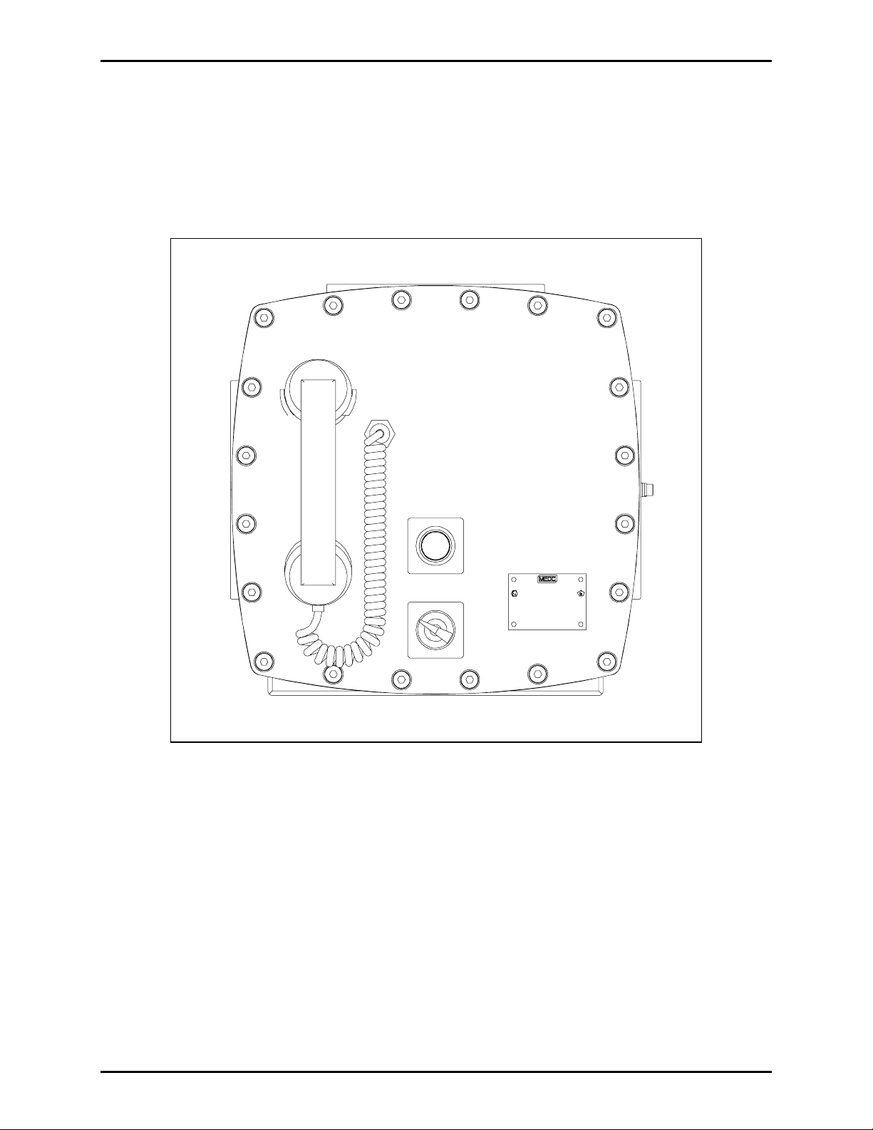
When the handset is removed from th e cradle, a magnetic r eed switch in the cra dle ta k es t he st ation
off-hook. In a ddition to the ha ndset and cord, a push- to-p age bu tton a nd a label are loca ted o n the front
cover. On the multi-party stations, a 5-party line selector switch is also included. See Figure 1.
®
Figure 1. Model 7805-301 Page/Party
Handset S tation - Front View
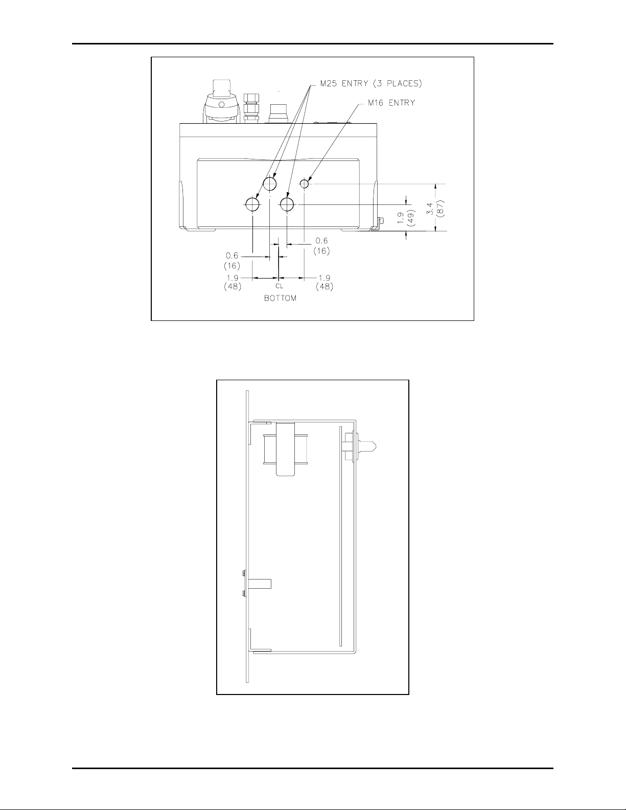
The cable gland entries for Models 780-301-and 7805-301 are shown in Figure 2. The following entries
are on the base: three M25 entries (two fitted with plugs); and one M16 entry.
\\s_eng\gtc proddoc s \st andard iom s - current release\42004 instr. manuals \ 42004-638l2. doc
6/98
Page 3
Model 780/7805-301 P age/Party
®
Handset Stations f or Cenelec Z one 1 Appli c ations Page: 3 of 15
Pub. 42004-638L2
Figure 2. Models 780-301 and 7805-301 Cable Gland Entries - Bottom View
N
OTE: Ensure any unused openings are sealed with proper fittings per local standards.
Figure 3. Plug-in Amplifier - Side View
\\s_eng\gtc proddoc s \st andard iom s - current release\42004 instr. manuals \ 42004-638l2. doc
6/98
Page 4
Model 780/7805-301 P age/Party
Block Di agram
®
Handset Stations f or Cenelec Z one 1 Appli c ations Page: 4 of 15
Pub. 42004-638L2
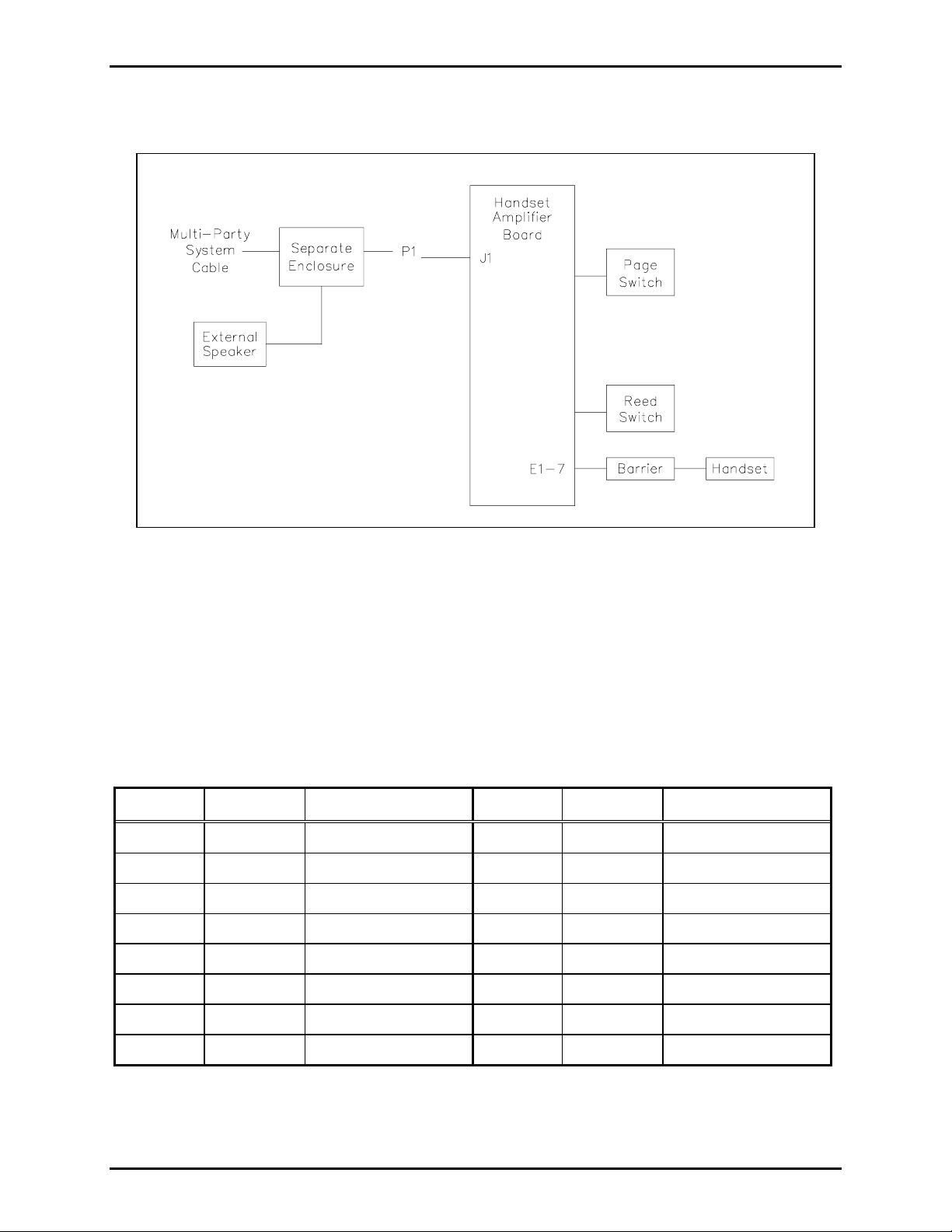
Figure 4. Model 701-202-EX Handset Station Block Diagram
P1 is the 16-pin male connector located on the back of the Base-16 printed circuit board assembly
(PCBA). It plugs into the socket located inside the enclosure. The socket provides connection to the
multi-party or single party cable containing the Page/Party
®
lines and ac power. The handset amplifier
PCB A connec ts t o the ha ndset and re e d swit ch using lug conne c tions E1 t o E7. S e e Figure 4.
Interfaces
The as sembly inter faces to t he multi-party cable a nd t he ex terna l loudspeak er via P 1, t h e 16- pin
connector, and connector J1. The pin functions for connector P1 are described below:
Pin No. Function Description Pin No. Function Descrip tion
1
2
3
4
5
6
PL_L1
PG_L1
MT_L1
N/C
SPKR_8
SPKR_16
Party line (L1) 9
Page line (L1) 10
Mute (L1) 11
No connection 12
Speaker (8-ohm) 13
Speaker (16-ohm) 14
PL_L2
PG_L2
MT_L2
N/C
EGND
SPKR_C
Party line (L2)
Page line (L2)
Mute (L2)
No connection
Ear th ground
Speaker (common)
7
8
\\s_eng\gtc proddoc s \st andard iom s - current release\42004 instr. manuals \ 42004-638l2. doc
6/98
N/C
AC_N
No connection 15
AC neutral 16
N/C
AC_H
No connection
AC ho t
Page 5
Pub. 42004-638L2
Model 780/7805-301 P age/Party
®
Handset Stations f or Cenelec Z one 1 Appli c ations Page: 5 of 15
Installation
Before installing Page/Party® equipment, design the system layout taking into consideration personnel
safety, operational function, convenience, and power cable length. In general, for 115 V ac systems the
total cable length should not exceed one mile (1.6 kilometer), but the length of cable between the stations
is not a crit ical fa c tor.
A separat e power feed is recommended to each station l oca t ed i n ha zardous ar eas . Wit h a separate feed,
individual stations can be de-energized for service or maintenance without affecting the power supply and
oper atio n of th e other sta tions i n the hazardous area.
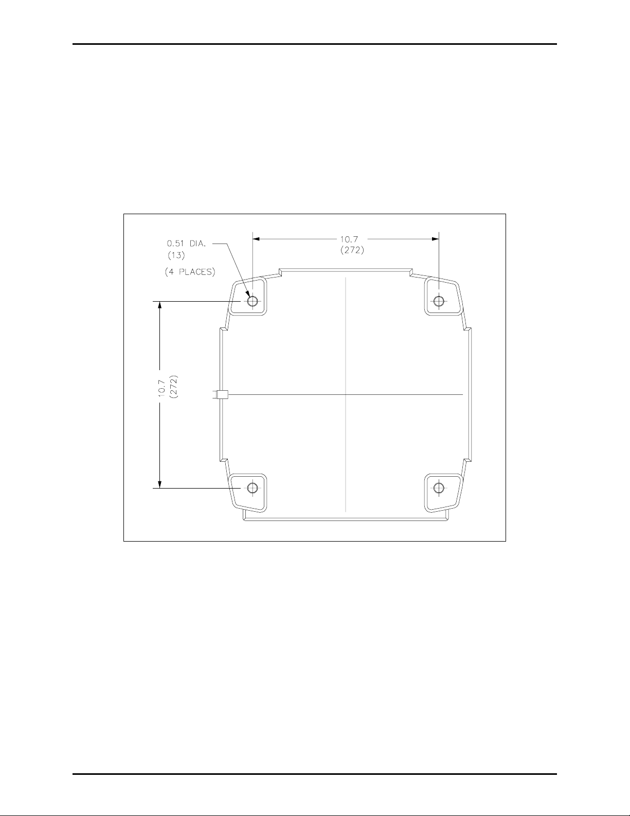
Figure 5. Mounting holes with dimensions in inches (mm)
\\s_eng\gtc proddoc s \st andard iom s - current release\42004 instr. manuals \ 42004-638l2. doc
6/98
Page 6

Pub. 42004-638L2
Model 780/7805-301 P age/Party
®
Handset Stations f or Cenelec Z one 1 Appli c ations Page: 6 of 15
Mounting
NOTE: The mounting surface must be able to support 55 lbs. (25 kg). The explosion-proof
enclosure is v ery heavy. Handle carefully to avo id damage to the uni t a nd personne l i njury.
1. Remove the cast aluminum front panel. Allow it to hang from the rear of the enclosure by means of
two retaining straps during installation. The straps serve as personnel safety feature and as a
saf eguard designe d to ens ure the flame path openin g is not nic ked, d e nted or oth erwise da maged
whi l e mo unt i n g t h e en c l os u re.
2. To maintain the explosion-proof integrity of the enclosure, all mounting hardware is located in
non-intrusive mounting holes under the front panel. The suggested mounting height of the station is
54 inches (137 cm) to the centerline of the enclosure. Use standard 1/2-inch socket head cap screws
or M12 bolts to secure the enclosure to a flat mounting surface.
3. After the enclosure is securely mounted, remove the plug-in amplifier as follows:
• Dis e ngag e the 24-pi n conn e c tor bet w e en the aluminum fr ont cov er and t he plug-in amplifier.
• Remove the four screws that secure the amplifier to the standoffs, and retain.
• Pull the amplifier straight toward you to disengage the 16-pin connector from the enclosure.
• Set the amplifier aside in a safe place while completing the installation.
4. Make up cable core ends as required for connection to the terminal blocks in the enclosure base.
5. Dismantle the outer parts of the 25 mm Ex ‘d’ cable gland(s) for the system cable and 16 mm Ex ‘d’
cable gland for the speaker cable and thread them onto the cable(s) in the correct order.
6. Feed the cable end(s) into the enclosure through the gland body or bodies and reassemble the outer
gland pa rts as direc te d by t he manu fac turer. Chec k tha t th e slack in t he cable i n side t he en cl o sure is
adequate but not excessive before tightening of the gland assembly.
7. Conn e c t cab le cor es to termina ls fol lowi ng the wire colors as illustrated in F igure 6 for single p arty
and Figure 7 for multi-party systems. The wire colors correspond to GAI-Tronics 60071 and 60072
Series System Cable and 60070 Speaker Cable. Connect the wires carefully and completely to the
termina l bloc k. An i mprop er termina tion may res ult in diminished st atio n perf ormance.
OTE: Determine if acoustical feedback is likely to be a problem, and adjust the speaker orientation,
N
if necessary. As a last resort, the associated speaker can be muted by moving the violet wire on the
enclosure on TB1 to terminal 7.
8. Install the amplifier by aligning the 16-pin connector to the enclosure socket and pushing straight in.
Install the four screws retained previously.
9. Inspect the gasket and ma chined rim of b oth th e cover and t he enc losure for nicks, scra tches, or other
dama ge that cou ld co mpromi se th e integrity of th e fla me p ath s eal. If damaged, the co ver ma y have
to be replaced.
10. Reconnect the 24-pin connector to the aluminum front cover and to the plug-in amplifier.
11. Secure the front cover to the cast aluminum enclosure using the bolts provided. Tighten the bolts
alternately with bolts that are diagonally opposite to ensure that the cover is evenly sealed.
\\s_eng\gtc proddoc s \st andard iom s - current release\42004 instr. manuals \ 42004-638l2. doc
6/98
Page 7

Model 780/7805-301 P age/Party
®
Handset Stations f or Cenelec Z one 1 Appli c ations Page: 7 of 15
Pub. 42004-638L2
Figure 6. Single Party Wiring Detail
\\s_eng\gtc proddoc s \st andard iom s - current release\42004 instr. manuals \ 42004-638l2. doc
6/98
Page 8

Model 780/7805-301 P age/Party
®
Handset Stations f or Cenelec Z one 1 Appli c ations Page: 8 of 15
Pub. 42004-638L2
Figure 7. Multi- Party Wir ing Detail
\\s_eng\gtc proddoc s \st andard iom s - current release\42004 instr. manuals \ 42004-638l2. doc
6/98
Page 9

Pub. 42004-638L2
Model 780/7805-301 P age/Party
®
Handset Stations f or Cenelec Z one 1 Appli c ations Page: 9 of 15
Operation
GAI-Tronics offers two types of Page/Party® systems: Page/Single-Party with one party line and one page
line, and Page/Multi-Party with five party lines and one page line allowing up to five simultaneous twoway conversations.
For Page/Single-Party, complete the following steps to make a page announcement:
1. Lift the handset from the cradle.
2. Depress and hold the press-to-page button on the front cover.
3. Speak directly into the microphone to broadcast your announcement over the loudspeakers.
4. Relea se t he press-to-page button, an d i f re q ues te d , wa i t f o r a r espons e.
The paged individual(s) responds by picking up a handset at any station and beginning communications.
For Page/Multi-Party, complete the following steps to make a page announcement:
1. Lift the handset from the cradle.
2. If party line conversation is desired, rotate the selector switch on the front cover to an unoccupied
party line.
3. Depress and hold the press-to-page button on the front cover.
4. Speak directly into the microphone to broadcast your announcement over the loudspeakers.
5. Relea se t he press-to-page button, an d i f re q ues te d , wa i t f o r a r espons e.
The paged individual(s) responds by picking up a station handset and turning the selector switch to the
requested party li ne.
With either type of equipment, the full duplex party line communication is not broadcast over the system
speakers. Other individuals can also pick up and join the conversation at any time. Always return the
handset to the cradle following a page or a party line conversation.
\\s_eng\gtc proddoc s \st andard iom s - current release\42004 instr. manuals \ 42004-638l2. doc
6/98
Page 10

Model 780/7805-301 P age/Party
Adjustments
®
Handset Stations f or Cenelec Z one 1 Appli c ations Page: 10 of 15
Pub. 42004-638L2
CAUTION
It is necessary to o pe n the ex p lo s ion-proo f enclosure to make adj us tments. Make adjustments only
when the conditio ns at your facility are such that no
explosive atmospheres ca n be pres ent.
Any a dju stme nt r equir es the remova l of the cast al u m inu m co v er. The s peak er amplifi er assembly i nsid e
includes o ne cont rol t hat permits adjustment whil e the assembly is still mount ed in its e nclosure, and
several internal controls that are accessible only by removing the assembly from the enclosure.
Adjustm ent with S peaker A mplifier Install ed
The User Lev el Adju stment (la be le d USER
ADJ) controls t h e volume of the associat e d s peak er. It is
located under the nameplate on the front panel of the speaker amplifier. Use a small flat-blade
screwdriver with an insulated shaft at least 4 inches long to make adjustment.
1. To access th e USER
ADJ control loosen (do not remove) the two screws that secure the nameplate.
2. Pivot the nameplate counterclockwise, exposing the access hole. A guide behind the access hole
helps direct the screwdriver to the USER
ADJ control.
3. Rotate the screwdriver clockwise to increase the volume, or counterclockwise to decrease the volume.
4. After completing the adjustment, pivot the nameplate clockwise back into position, then tighten the
two screws.
Adjustm ents wit h Speaker Amplifi er Remov ed
Although they typically require no adjustments, the Speaker Amplifier Level, Receiver Sidetone Level,
Audio Transmit (Microphone Gain) Level, and Handset Receiver Volume can be set with internal
controls. Each adjustment is clearly labeled:
• Speaker Amplifier: adjusts the speaker volume. It is also accessible without removing the speaker
amplifier. (See instructions for USER
ADJ above.)
• Receiver Sid et o n e: the amount of signal transmitted from the microphone to the receiver of the
handset.
• Microphone Gain: adjusts the gain level from the microphone signal to the page or party lines.
• Receiver Volume: adjusts the gain level from a party line to the receiver.
\\s_eng\gtc proddoc s \st andard iom s - current release\42004 instr. manuals \ 42004-638l2. doc
6/98
Page 11

Pub. 42004-638L2
Model 780/7805-301 P age/Party
®
Handset Stations f or Cenelec Z one 1 Appli c ations Page: 11 of 15
To make these adjustments, remove the assembly from its enclosure and make a temporary connection
between the assembly and the enclosure as described in the following steps:
1. Loosen the four captive screws that secure the front panel.
2. Remove the assembly from the enclosure.
3. Connect the assembly to the enclosure using a Model 10440-002 Maintenance Cable between P1 on
the assembly and J1 on the enclos ure.
4. Locate the control on the appropriate PCBA. Using a small flat-blade screwdriver with an insulated
shaft, turn a control clockwise to increase the volume or threshold; turn it counterclockwise to
decreas e the volume or threshol d.
5. When you are done with the adjustment:
a) Disconnect the Model 10440-002 Maintenance Cable.
b) Insert the assembly into the enclosure.
c) Tighten the four screws.
\\s_eng\gtc proddoc s \st andard iom s - current release\42004 instr. manuals \ 42004-638l2. doc
6/98
Page 12

Pub. 42004-638L2
Model 780/7805-301 P age/Party
®
Handset Stations f or Cenelec Z one 1 Appli c ations Page: 12 of 15
Maintenance
In or der t o verif y and ensure explosion-p roof inte grit y, per form regular preve ntive maintena nce an d
inspection checks on the GAI-Tronics explosion-proof enclosure. The GAI-Tronics Field Service
Department can f ormulate a service contract to su it s p ecific pr ev entive maintenance needs.
CAUTION
Remove power from the enclosure b efore performing any mainte na nce.
Use the following procedures to ensure reliable operation of your equipment:
1. Remove power from the enclosure.
2. Unbolt the cover, and remove the amplifier from the enclosure.
3. Visu ally check the i nter ior of the enclos ure f or signs of c ontamination. Cont aminati on inside t he
enclosure could mean that t he con duit seals or cab le gla n d seals have been compromised.
4. Ensure the gasket and hardware are in place and in good condition. Restore power to the unit.
In certain circumstances, it may be necessary to re-terminate wire connections to some or all of the
enclosures in a system. When this is done, strip the wires back to clean copper, reconnect to each
terminal.
\\s_eng\gtc proddoc s \st andard iom s - current release\42004 instr. manuals \ 42004-638l2. doc
6/98
Page 13

®
Model 780/7805-301 P age/Party
Handset Stations f or Cenelec Z one 1 Appli c ations Page: 13 of 15
Troubl eshooting
The table below describes possible solutions for some common problems.
Problem Solution
Pub. 42004-638L2
Speaker level requires
adjustment.
Outgoing conversation level
Adjus t the S peaker V olume Control, la beled USER ADJ, at the
amplifier.
Adjust Microphone Gain at the amplifier.
requ ires adjustment.
Incoming conversation level
Adjust the Receiver Volume Control at the amplifier.
requ ires adjustment.
Feedback/distortion (a hum or
buzz on the line) occu rs during
all Page/Party
®
station operation.
1. Adjust the Receiver Volume Control at the amplifier.
2. The line may be improperly terminated. Inspect the system cable
for loose conn e c tio ns, short s, and grou nds. Line balance
assembly connections are critical.
Sidetone * requ ires a d justment.
*Hearing one’s own voice in the
receiver of the handset.
1. Adjust the Receiver Sidetone at the amplifier.
2. Check that the system cable connections to the resistors in the
line balance assembly are properly connected to the line balance
assembly resistors.
Crosstalk occurs. One or more system cable pairs may be improperly terminated.
Visually insp ect t h e system cable connections for a ccidental crossing
of the cable pairs or grounds.
Feedback during page of nearby
handset s tat io n.
Use the muting feature in the amplifier enclosure at the terminal
blocks.
\\s_eng\gtc proddoc s \st andard iom s - current release\42004 instr. manuals \ 42004-638l2. doc
6/98
Page 14

Pub. 42004-638L2
Model 780/7805-301 P age/Party
®
Handset Stations f or Cenelec Z one 1 Appli c ations Page: 14 of 15
Specification s
Electrical
Voltage ..............................................................................90 to 140 V ac (120 V ac nominal) 50/60 Hz
Power Consumed ........................ Zero/maximum signal (12 watts): 15 VA, 10.5 watts; 53 VA, 34 watts
Speaker Amplifier
Output:......................................................................... 12 watts minimum, with nominal supply voltage
Output limiter:.........................................................................2.16 Vpeak (adjustable via configuration)
Voltage gain.................................................................................................26 dB maximum, adjustable
Frequency response..................................................................250–4000 Hz, +0 dB, -3 dB ref. to 1 kHz
Distortion....................................................................................1% maximum THD @ 1 kHz, 12 watts
Input Impedance......................................................................................................... 50k ohms nominal
Audio input from line...........................................1.5 Vrms nominal (depends on distance) from 33 ohm
Handset
Output.............................................................................................. 1.5 Vrms nominal into 33-ohm lo a d
Output limiter..............................................................................................................1.5 Vrms nominal
Gain........................................................ 55 dB nominal (below limiter level) adjustable from 40-63 dB
Frequency response..................................................................325–7000 Hz, +0 dB, -3 dB ref. to 1 kHz
Distortion................................................................................................1.5% maximum THD @ 1 kHz
Recommended environment ...............................................................................Greater than 50 dB SPL
Mechanical
Dimensions ...........................................14.4 H × 14.4 W × 7.83 D inches (367 × 367 × 199 mm) overall
Enclosure material......................................................................................................... LM25TF, Epoxy
Handset material......................................................................................................................Gray ABS
Handset microphone........................................................................................Dynamic, noise canceling
Handset receiver.........................................................Dynamic, hearing aid compatible per FCC part 68
Cable............................................................................Hytrel
®
, Retractile, 6-foot (1.8m) when extended
Cradle...................................................................................................Fixed; built-in off-hook detector
External controls .............................................................Press-to-page switch; party line selector switch
Internal controls ........................... Tone adjust, sidetone, handset receiver volume, line level, AGC level
Enviro nmental
Temperature range........................................-4° F to +151° F (-20° C to +66° C), Operating and storage
Humidity ................................................................................................................ 95% non-condensing
\\s_eng\gtc proddoc s \st andard iom s - current release\42004 instr. manuals \ 42004-638l2. doc
6/98
Page 15

®
Model 780/7805-301 P age/Party
Handset Stations f or Cenelec Z one 1 Appli c ations Page: 15 of 15
Replaceme nt Parts
Model Number Description
10111-007 Handset Assembly with 6-foot Hytrel® Cord
12511-001 Dynamic Transmitter and Cap
12530-001 Transformer/Connector Subassembly
13204-002 Receiver Cap
701-202-EX Amplifier Assembly
Ref erence Material
Refe rence to Assembly/Model D rawings
Pub. 42004-638L2
Published by Title GAI-Tronics Ref. No.
GAI-Tronics Single Party Handset Station Outline Dwg. 222-147
GAI-Tronics Multi-Party Handset Station Outline Dwg. 222-148
GAI-Tronics Plug-in Amplifier Outline Dwg. 72009
\\s_eng\gtc proddoc s \st andard iom s - current release\42004 instr. manuals \ 42004-638l2. doc
6/98
Page 16

Warranty
Equipment. GAI-Tronics warrants for a period of one (1) year from the date of shipment, that any
GAI-Tronics equipment supplied hereunder shall be free of defects in material and workmanship, shall
comply with the then-current product specifications and product literature, and if applicable, shall be fit
for the purpose specified in the agreed-upon quotation or proposal document. If (a) Seller’s goods prove
to be defective in workmanship and/or material under normal and proper usage, or unfit for the purpose
specified and agreed upon, and (b) Buyer’s claim is made within the warranty period set forth above,
Buyer may return such goods to GAI-Tronics’ nearest depot repair facility, freight prepaid, at which time
they will be repaired or replaced, at Seller’s option, without charge to Buyer. Repair or replacement shall
be Buyer’s sole and exclusive remedy. The warranty period on any repaired or replacement equipment
shall be the greater of the ninety (90) day repair warranty or one (1) year from the date the original
equipment was shipped. In no event shall GAI-Tronics warranty obligations with respect to equipment
exceed 100% of the total cost of the equipment supplied hereunder. Buyer may also be entitled to the
manufacturer’s warranty on any third-party goods supplied by GAI-Tronics hereunder. The applicability
of any such third-party warranty will be determined by GAI-Tronics.
Services. Any services GAI-Tronics provides hereunder, whether directly or through subcontractors,
shall be performed in accordance with the standard of care with which such services are normally
provided in the industry. If the services fail to meet the applicable industry standard, GAI-Tronics will
re-perform such services at no cost to buyer to correct said deficiency to Company's satisfaction provided
any and all issues are identified prior to the demobilization of the Contractor’s personnel from the work
site. Re-performance of services shall be Buyer’s sole and exclusive remedy, and in no event shall GAITronics warranty obligations with respect to services exceed 100% of the total cost of the services
provided hereunder.
Warranty Periods. Every claim by Buyer alleging a defect in the goods and/or services provided
hereunder shall be deemed waived unless such claim is made in writing within the applicable warranty
periods as set forth above. Provided, however, that if the defect complained of is latent and not
discoverable within the above warranty periods, every claim arising on account of such latent defect shall
be deemed waived unless it is made in writing within a reasonable time after such latent defect is or
should have been discovered by Buyer.
Limitations / Exclusions. The warranties herein shall not apply to, and GAI-Tronics shall not be
responsible for, any damage to the goods or failure of the services supplied hereunder, to the extent
caused by Buyer’s neglect, failure to follow operational and maintenance procedures provided with the
equipment, or the use of technicians not specifically authorized by GAI-Tronics to maintain or service the
equipment. THE WARRANTIES AND REMEDIES CONTAINED HEREIN ARE IN LIEU OF AND
EXCLUDE ALL OTHER WARRANTIES AND REMEDIES, WHETHER EXPRESS OR IMPLIED BY
OPERATION OF LAW OR OTHERWISE, INCLUDING ANY WARRANTIES OF
MERCHANTABILITY OR FITNESS FOR A PARTICULAR PURPOSE.
Return Policy
If the equipment requires service, contact your Regional Service Center for a return authorization number
(RA#). Equipment should be shipped prepaid to GAI-Tronics with a return authorization number and a
purchase order number. If the equipment is under warranty, repairs or a replacement will be made in
accordance with the warranty policy set forth above. Please include a written explanation of all defects to
assist our technicians in their troubleshooting efforts.
Call 800-492-1212 (inside the USA) or 610-777-1374 (outside the USA) for help identifying the
Regional Service Center closest to you.
(Rev. 10/06)
 Loading...