

Page 1

Pub. 42004-211B
GAI-TRONICS® CORPORATION
A HUBBELL COMPANY
Model 758-001
Weatherproof Speaker Ampli fi er Enclosure
Confidentiality Notice
This manua l is provide d solely as an oper ational, installation, and ma inte nance guid e and co ntai ns
sensitive business and te chni c al information that is con f idential and pr opri et ary to GAI- Tronics. GAITronics retains all intellectual property and other rights in or to the information contained herein, and
such information may on ly be u sed in conn e c tion with the operation of your GAI-Tronics p rodu c t or
system. This manu al may not be dis close d in a ny form, in whole or in part, direct ly or i ndir ectly, to a ny
third pa r ty.
General Information
The Model 758-001 Weatherproof Speaker Amplifier Enclosure is an important component of the 700
Series Page/Party< system. I t is co nstructed of ca st alu minum a lloy, which is extrem e ly wea therp roof
and corrosion-resistant, and can be used in either indoor or outdoor applications.
This enclosure is designed for 115 V ac input systems, and is equipped with terminal strips for connecting
inter-station system cable. The GAI-Tronics Model 751-001 Speaker Amplifier mates directly into this
enclosure.
Installation
CAUTION
indic at ed on t he approv al listing in th e Speci f ication section of th is manual. Such ins tallation may
cause a safety ha za rd and consequent injury or property damage.
When installing an a dd-o n sta tion, c onsult the s yste m layou t dia grams at t he end of this ma nual. These
figures, when used in conjunction with the station installation information and cable layout guide, should
provide all the information necessary to install additional Page/Party< stations.
Do not install this equipment in hazardous areas or areas other than those
GAI-Tronics Corporation 400 E. Wyomissing Ave. Mohnton, PA 19540 USA
610-777-1374 800-492-1212 Fax: 610-796-5954
ISIT WWW.GAI-TRONICS.COM FOR PRODUCT LITERATURE AND MANUALS
V
Page 2

Pub. 42004-211B
Model 758-001 Weatherproof Speaker Amplifier Enclosure Page:
2 of 8
Enclos ure Placement
All GAI-Tronics Page/Par t y® units are wired in parallel. Good system layout design minimizes the cable
required for each installation. GAI-Tronics multi-conductor cable, designed especially for this
application, is recommended. The number, size, and color-coding of conductors are listed in the
accompanying system connection diagrams.
System layout and power cable length are very important when installing Page/Party< equipment.
Although it varies for different systems, the general guideline is that the total power cable length should
not exceed 1 mile (5280 feet) for 115 V ac systems. The total cable length is the most important
consideration while cable length between the stations is generally not a factor.
Mounting
The Model 758-001 Weatherproof Speaker Amplifier Enclosure is supplied with pre-drilled cable
openings and conduit hubs with top and bottom cap plugs in place to prevent contamination.
Whenever possible, do not enter an enclosure from the top: bottom entry helps to prevent moisture from
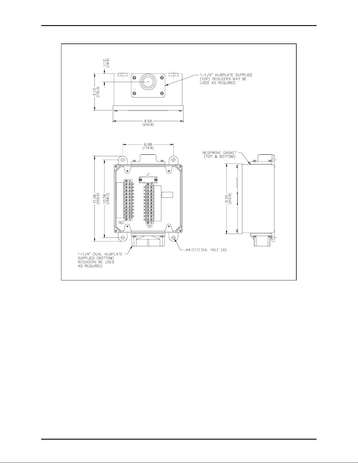
dripping onto the terminals or PCBAs. There are four 0.44-inch diameter mounting holes in the corners
of the amplifier enc losure. Refer t o Figur e 1 . The sugges ted mounting h e ight f or all stat ion enc losures is
54 inches (137 cm).
\\s_eng\gtc proddoc s \st andard iom s - current releas e\ 42004 ins t r. m anuals \ 42004-211b. doc
10/03
Page 3
Pub. 42004-211B
Model 758-001 Weatherproof Speaker Amplifier Enclosure Page:
3 of 8
Figure 1. Mounting Details for Model 758-001 Speaker Amplifier Enclosure
\\s_eng\gtc proddoc s \st andard iom s - current releas e\ 42004 ins t r. m anuals \ 42004-211b. doc
10/03
Page 4

Pub. 42004-211B
Model 758-001 Weatherproof Speaker Amplifier Enclosure Page:
4 of 8
Wiring
Attach conduit to the enclosure. Feed the wiring through the conduit, and bring it into the enclosure. See
Figure 2. Follow the wire colors carefully, because the colors correspond to GAI-Tronics 60029 or 60038
Series cable. The wires must be spade-lugged and connected carefully and completely to the terminal
block. An i mproper t ermi nation may d imini sh stat ion perfor mance.
Mutual Muting
In the event that feedback occurs within an area and repositioning of the system speakers does not help,
mutual muting may be used to correct this problem.
The following steps mutually mutes adjacent amplifiers/handsets within a zone.
1. Ensure that the purple lugged wire on the Model 758-001 Enclosure is connected to terminal 7 of
TB1.
2. Connect terminal TB1-7 of the handset station to TB1-7 of the Model 758-002 Enclosure within the
zone that is causing feedback. This is done by using the spare system wire (orange conductor) from
within the system cable that runs between the stations.
Figure 2. Model 758-001 Wiring Details
\\s_eng\gtc proddoc s \st andard iom s - current releas e\ 42004 ins t r. m anuals \ 42004-211b. doc
10/03
Page 5

Pub. 42004-211B
Model 758-001 Weatherproof Speaker Amplifier Enclosure Page:
5 of 8
Maintenance
Regular inspe c tion and a good pre vent ive mainte nance progra m w ill increa se the reliabil ity of your
GAI-Tronics s tat ion. The GAI-T ronics Field Service D ep artment can formula te a service contrac t suited
to your facility’s specific need for preventive maintenance.
®
In addition, the following procedure can be used to keep Page/Party
systems opera t in g eff ectively.
WARNING
Before performing any of the following preventive maintenance steps, remove
all power fro m t he s tat ion.
1. Remove the amplifier from the enclosure.
2. Visu ally check the i nterior of the enclos ure f or sig ns of contamination suc h as dust, condens ati on or
process liqui d.
3. Using the No. 10440-002 Maintenance Cable, plug the amplifier into the connector in the enclosure.
Check, and if necessary, adjust the amplifier to maximize performance.
4. Reinstall the amplifier in the enclosure. Ensure that all gaskets and hardware are in place. Failure to
install the gaskets, which also act as spacers, can result in damage to the connectors on the amplifiers
and insi de the e nclos ur es and ca n cause sys tem fault s.
It may become necessary to re-terminate some or all of the enclosures in a system. If so, strip the wires
back to clean copper and connect only one wire to each connector to allow for easier future
troubleshooting.
Troubleshooti ng
The following table lists some hints to aid technicians in troubleshooting.
Problem Solution
Feedback occu rs
only during
page.
1. If a speaker is close to t he station, try using th e muting featur e in t he amp lifi er
enclosure at the terminal blocks. Connect the violet wire at TB1-8 to TB1-7.
Refer to the wiring diagram.
2. Ensu re tha t speakers at tached to other stat ions locate d near by are not point e d
in you r direction. If changing the orient atio n of th e other speakers has n o
effect, mutual muting may be required. Mutual muting silences all the
speakers within proximity to the affected stations during a page from any one
of the mutually muted stations.
Connect the orange wire (spare) to the TB1-7 of all the stations to be mutually
muted. Note: If too many stations are selected, paging coverage can be
adversel y affected.
3. Check line terminations at the line balance assembly. Line balance assembly
connectio ns are critical.
Crosstalk
occurs.
One or more system cable pairs may be improperly terminated. Visually inspect
the syste m c abl e connec tions for acc idental crossing of the ca ble pairs or grounds.
\\s_eng\gtc proddoc s \st andard iom s - current releas e\ 42004 ins t r. m anuals \ 42004-211b. doc
10/03
Page 6

Pub. 42004-211B
Model 758-001 Weatherproof Speaker Amplifier Enclosure Page:
6 of 8
Specification s
Con s tru ction/ f i n ish................................................................................ Cast alumi num/g ray polyu rethane
Mounting ........................................................... Wall or column, four 0.44-inch diameter mounting holes
Connections .............................................................................Internal screw-type barrier terminal blocks
Dimensions ................................................. 11.58 H × 9.55 W × 5.1 D inches; (289.5 × 242.6 × 129 mm)
Shipping weight .................................................................................................................. 5 lbs. (2.3 kg)
Approvals.....................NRTL Listed for USA and Canada................. Class I, Div. 2, Groups A, B, C, D;
Class I I, Div. 2, Groups F and G;
and Class III, Div. 2,
when used with listed GAI-Tronics Model 751 120 V ac Series Speaker Amplifier
Outdoor environmental rating ................................................................................................... NEMA 4X
REPLACEMENT PARTS
Part Numb e r Descrip tio n
10440-002 Maintenance Cable
46101-012 Screw Kit
12535-002 Hardware for Harness Assembly
12566-001 1-1/4” Hub Kit
12566-002 Dual 1-1/4” Kit
25007-004 Closure Plug NPT 1-1/4
61509-004 Harness Assembly
62005-011 11-point Terminal Block
\\s_eng\gtc proddoc s \st andard iom s - current releas e\ 42004 ins t r. m anuals \ 42004-211b. doc
10/03
Page 7

Pub. 42004-211B
Model 758-001 Weatherproof Speaker Amplifier Enclosure Page:
7 of 8
\\s_eng\gtc proddoc s \st andard iom s - current releas e\ 42004 ins t r. m anuals \ 42004-211b. doc
10/03
Page 8

Pub. 42004-211B
Model 758-001 Weatherproof Speaker Amplifier Enclosure Page:
8 of 8
\\s_eng\gtc proddoc s \st andard iom s - current releas e\ 42004 ins t r. m anuals \ 42004-211b. doc
10/03
Page 9

Warranty
Equipment. GAI-Tronics warrants for a period of one (1) year from the date of shipment, that any
GAI-Tronics equipment supplied hereunder shall be free of defects in material and workmanship, shall
comply with the then-current product specifications and product literature, and if applicable, shall be fit
for the purpose specified in the agreed-upon quotation or proposal document. If (a) Seller’s goods prove
to be defective in workmanship and/or material under normal and proper usage, or unfit for the purpose
specified and agreed upon, and (b) Buyer’s claim is made within the warranty period set forth above,
Buyer may return such goods to GAI-Tronics’ nearest depot repair facility, freight prepaid, at which time
they will be repaired or replaced, at Seller’s option, without charge to Buyer. Repair or replacement shall
be Buyer’s sole and exclusive remedy. The warranty period on any repaired or replacement equipment
shall be the greater of the ninety (90) day repair warranty or one (1) year from the date the original
equipment was shipped. In no event shall GAI-Tronics warranty obligations with respect to equipment
exceed 100% of the total cost of the equipment supplied hereunder. Buyer may also be entitled to the
manufacturer’s warranty on any third-party goods supplied by GAI-Tronics hereunder. The applicability
of any such third-party warranty will be determined by GAI-Tronics.
Services. Any services GAI-Tronics provides hereunder, whether directly or through subcontractors,
shall be performed in accordance with the standard of care with which such services are normally
provided in the industry. If the services fail to meet the applicable industry standard, GAI-Tronics will
re-perform such services at no cost to buyer to correct said deficiency to Company's satisfaction provided
any and all issues are identified prior to the demobilization of the Contractor’s personnel from the work
site. Re-performance of services shall be Buyer’s sole and exclusive remedy, and in no event shall GAITronics warranty obligations with respect to services exceed 100% of the total cost of the services
provided hereunder.
Warranty Periods. Every claim by Buyer alleging a defect in the goods and/or services provided
hereunder shall be deemed waived unless such claim is made in writing within the applicable warranty
periods as set forth above. Provided, however, that if the defect complained of is latent and not
discoverable within the above warranty periods, every claim arising on account of such latent defect shall
be deemed waived unless it is made in writing within a reasonable time after such latent defect is or
should have been discovered by Buyer.
Limitations / Exclusions. The warranties herein shall not apply to, and GAI-Tronics shall not be
responsible for, any damage to the goods or failure of the services supplied hereunder, to the extent
caused by Buyer’s neglect, failure to follow operational and maintenance procedures provided with the
equipment, or the use of technicians not specifically authorized by GAI-Tronics to maintain or service the
equipment. THE WARRANTIES AND REMEDIES CONTAINED HEREIN ARE IN LIEU OF AND
EXCLUDE ALL OTHER WARRANTIES AND REMEDIES, WHETHER EXPRESS OR IMPLIED BY
OPERATION OF LAW OR OTHERWISE, INCLUDING ANY WARRANTIES OF
MERCHANTABILITY OR FITNESS FOR A PARTICULAR PURPOSE.
Return Policy
If the equipment requires service, contact your Regional Service Center for a return authorization number
(RA#). Equipment should be shipped prepaid to GAI-Tronics with a return authorization number and a
purchase order number. If the equipment is under warranty, repairs or a replacement will be made in
accordance with the warranty policy set forth above. Please include a written explanation of all defects to
assist our technicians in their troubleshooting efforts.
Call 800-492-1212 (inside the USA) or 610-777-1374 (outside the USA) for help identifying the
Regional Service Center closest to you.
(Rev. 10/06)
 Loading...