

Page 1

Pub. 42004-194M
GAI-TRONICS® CORPORATION
A HUBBELL COMPANY
Model 234 Stanchion Assembly and Model
234SBA Stanchion Broadcast Assemblies
Confidentiality Notice
This manual is provided solely as an operational, installation, and maintenance guide and contains
sensitive business and technical information that is confidential and proprietary to GAI-Tronics.
GAI-Tronics retains all intellectual property and other rights in or to the information contained herein,
and such information may only be used in connection with the operation of your GAI-Tronics product or
system. This manual may not be disclosed in any form, in whole or in part, directly or indirectly, to any
third party.
General Information
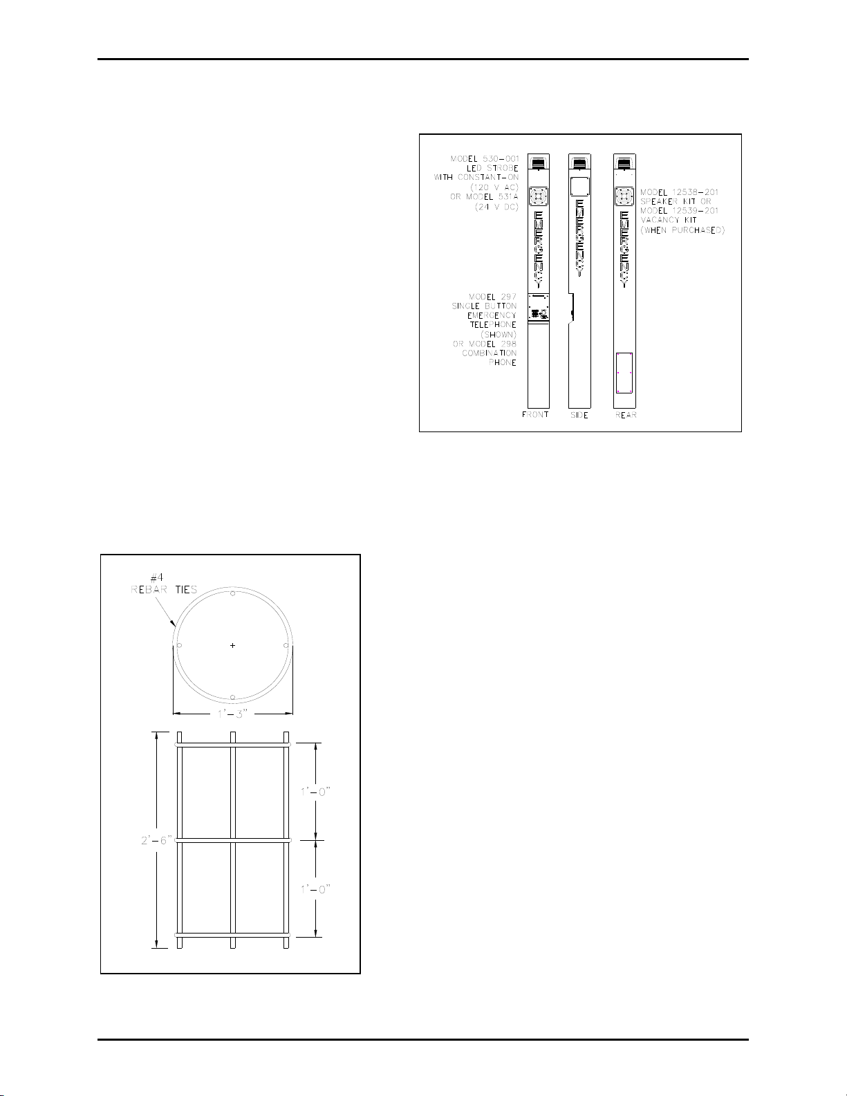
The Model 234 Stanchion Assembly is part of a completely integrated emergency communications
station. The Model 234SBA Stanchion Broadcast Assembly helps to insure public safety by combining
two-way communications with one-way public address broadcasting.
The Model 234 Stanchion Assembly and Model 234SBA Stanchion Broadcast Assembly are designed to
house a GAI-Tronics 39x or 27x Series Flush-Mount Telephone and a Model 530-001 or 531A Strobe.
Both stanchion assemblies are over 9 feet tall, making it easily located by potential users. Each Model
234SBA is capable of being equipped with up to four public address speakers.
GAI-Tronics enhanced emergency telephones are designed for isolated high-risk areas requiring
emergency communications equipment. Emergency telephone users simply press the clearly labeled
emergency push button for immediate connection to a user-programmed central security telephone
number.
The strobe creates added visibility to emergency telephone locations by providing a constant-on lamp that
automatically flashes when the emergency button is pressed. The telephone is also highly visible; a light
mounted in the stanchion shines on the front of the telephone to illuminate the telephone for nighttime
use.
The complete emergency stanchion, with or without public address, is shipped in two stages. The Model
84504-201 Hardware Kit is usually shipped in advance followed by the remaining assemblies (Model
84501-201 or Model 84509-201 Stanchion Body, Model 84502-201 Clear Lens, and Model 84503-30x
LED Panel Light Assembly). Both the Model 234 and Model 234SBA use the same hardware kit.
GAI-Tronics Corporation 400 E. Wyomissing Ave. Mohnton, PA 19540 USA
610-777-1374 800-492-1212 Fax: 610-796-5954
V
ISIT WWW.GAI-TRONICS.COM FOR PRODUCT LITERATURE AND MANUALS
Page 2
Pub. 42004-194M
234 Stanchion Assembly and Model 234SBA Stanchion Broadcast Assembly Page 2 of 11
Mounting
A concrete pier is required to support both of the
stanchion assemblies. GAI-Tronics provides the
Model 84504-201 Hardware Kit to aid with the
construction of this pier.
We recommend using 3,000 psi grade concrete
as a minimum. The pier must be strong enough
to support a structure that is 9-1/2 feet tall and
weighs 250 lbs.
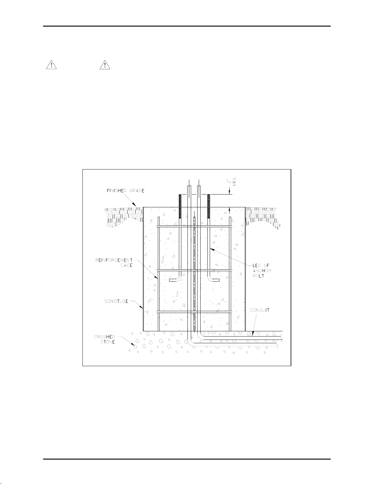
Reinforcement Cage
We recommend that the concrete base be 3 feet
deep and 18 inches wide, and that a
reinforcement cage be used. The reinforcement
cage is not provided by GAI-Tronics. The
following materials are necessary to construct the
reinforcement cage:
Figure 1. Model 234SBA shown
four #4 rebars;
three #4 ties;
one 18-inch sonotube.
1. Construct the reinforcement cage by placing a horizontal
member in the center of the rebar.
2. Place the two remaining horizontal members 12 inches
from that center point. See Figure 2. The top of the
cage should be 3 inches below the top of the pier.
3. The reinforcement cage in Figure 2 shows the maximum
diameter that is suitable for a customer-provided 18-inch
sonotube.
4. Install two conduits in the pier—one for the telephone
wire and one for the electrical power wire.
OTE: These conduits MUST be kept separate to
N
prevent interference from occurring on the audio lines.
Conduits are not s
NOTE: These conduits MUST be
kept separate to prevent interference from occurring on
the audio lines. Conduits are not supplied by GAITronics.
Figure 2. Reinforcement Cage
f:\standard ioms - current release\42004 instr. manuals\42004-194m.doc
11/12
Page 3
Pub. 42004-194M
234 Stanchion Assembly and Model 234SBA Stanchion Broadcast Assembly Page 3 of 11
Installation
ATTENTION
accordance with the National Electrical Code and applicable local codes.
The following information provides guidelines on the installation of various components of the
emergency station. Grounding electrode conductor (not depicted in the illustration) must be constructed
in accordance with the National Electrical Code and applicable local codes.
Installation should be performed by qualified personnel and only in
Model 84504-201 Hardware Kit Installation
The Model 84504-201 Hardware Kit includes four anchor bolts, which should be installed so that they
extend 3 inches above the top of the pier surface. See Figure 3.
Figure 3. Front View
f:\standard ioms - current release\42004 instr. manuals\42004-194m.doc
11/12
Page 4
Pub. 42004-194M
234 Stanchion Assembly and Model 234SBA Stanchion Broadcast Assembly Page 4 of 11
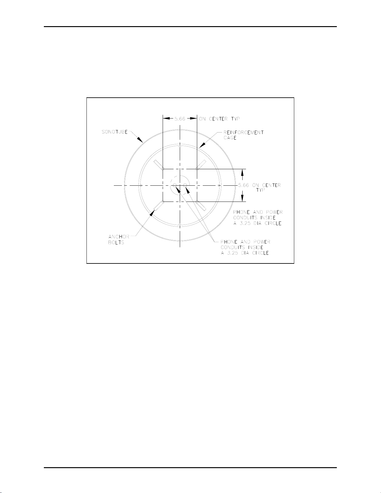
Use the template provided in the hardware kit for anchor bolt positioning, or see Figure 4 for dimensions.
The 3-inch leg of the anchor bolts should point to the outside of the tube. Center lines should be
measured across the corners.
N
OTE: The stanchion should not be mounted until the concrete has been allowed to cure for a minimum
of 24 hours.
Figure 4. Top View
f:\standard ioms - current release\42004 instr. manuals\42004-194m.doc
11/12
Page 5

Pub. 42004-194M
234 Stanchion Assembly and Model 234SBA Stanchion Broadcast Assembly Page 5 of 11
Model 84501-201 and 84509-201 Stanchion Main Body Installa tion
1. If the concrete is not level, find the anchor rod at the highest point of the concrete, and screw one ¾-
inch heavy hex nut 1-
1
/8 inches above the concrete surface (measuring to the top of the nut).
See Figure 5.
2. Adjust the remaining three hex nuts to be level with the first. Place one washer over each heavy hex
nut. See Figure 5 and Figure 6.
Figure 5. Exploded View
3. Before mounting the stanchion, unscrew the four security screws on the rear access panel, and remove
the panel.
4. Apply a small amount of clear RTV silicone sealant or equivalent to each screw thread to reduce the
possibility of rust forming in the screw threads.
N
OTE: GAI-Tronics Model 233-001 Security Screwdriver is required to remove security screws.
5. Place the stanchion on top of the four level, heavy hex nuts.
6. Entering through the rear access panel hole, place the four remaining washers on the anchor bolts, and
secure with the ¾-inch hex nuts. Do not install the access panel cover until the wiring is complete.
f:\standard ioms - current release\42004 instr. manuals\42004-194m.doc
11/12
Page 6

Pub. 42004-194M
234 Stanchion Assembly and Model 234SBA Stanchion Broadcast Assembly Page 6 of 11
NOTE: A ¼-inch air gap must exist between the base of the stanchion and the top of the concrete pier.
See Figure 6. This air gap must not
be obstructed with soil, mulch, stone, etc.
Figure 6. Assembled View
The unit should be installed and grounded in accordance with national and local electrical codes.
N
OTE: A grounding stud connection has been provided inside the rear access panel.
f:\standard ioms - current release\42004 instr. manuals\42004-194m.doc
11/12
Page 7

Pub. 42004-194M
234 Stanchion Assembly and Model 234SBA Stanchion Broadcast Assembly Page 7 of 11
Model 84503-30x Stanchion Panel Light Installa tion
1. Align the stanchion panel light assembly inside the
stanchion as shown in Figure 7.
2. Model 84503-301: Extend the black (hot), the white
(neutral) and the green (ground) wires to the base of
the stanchion (these wires will be connected later,
along with the strobe wires, to the incoming power
wires in accordance with the electrical codes).
Model 84503-302: Extend the black (−) and the white
(+) wires to the base of the stanchion (these wires will
be connected later, along with the strobe wires, to the
incoming power wires in accordance with the
electrical codes).
3. Secure the light assembly with the two mounting
screws provided. Apply a small amount of clear RTV
silicone sealant or equivalent to each screw thread to
reduce the possibility of rust forming in the screw
threads.
Figure 7. Stanchion Panel Light Assembly
f:\standard ioms - current release\42004 instr. manuals\42004-194m.doc
11/12
Page 8

Pub. 42004-194M
234 Stanchion Assembly and Model 234SBA Stanchion Broadcast Assembly Page 8 of 11
Model 530-001 or 531A Strobe and 84502-201 Lens Cov er Installation
1. Insert the strobe’s seven 15-foot wires through the stanchion’s threaded nipple, and allow the wires to
extend to the base of the stanchion. See Figure 8.
2. Screw the strobe onto the threaded nipple. Secure the Model 84502-201 Lens Cover with four
security screws.
3. Apply a small amount of clear RTV silicone sealant or equivalent to each screw thread to reduce the
possibility of rust forming in the screw threads.
4. Separate the orange and violet wires necessary for the telephone connection, and extend those wires
through the stanchion cutout for the telephone.
Figure 8. Strobe Assembly
f:\standard ioms - current release\42004 instr. manuals\42004-194m.doc
11/12
Page 9

Pub. 42004-194M
234 Stanchion Assembly and Model 234SBA Stanchion Broadcast Assembly Page 9 of 11
Model 40201-010 Battery Installation (Model 234SBA Only)
1. Batteries are shipped separately and are to be installed on site. Pay strict attention to battery polarity,
as reverse power will cause damage to internal components.
2. Make the wiring connection to the electronics module labeled 12V
BATTERY (red+, black−) with
battery cable. It is recommended that this be left disconnected from the module until you are ready to
power up the unit.
3. Attach the fast-on connectors to the batteries observing polarity (red+, black−) per drawing 73520.
4. Secure the batteries into L-bracket inside stanchion under telephone opening.
OTE: If the stanchion body does not have any L-brackets, the battery must be set in the bottom of
N
the stanchion to the side, away from the conduit entries.
Refer to Pub. 42004-415, Model 10458-10x Electronics Paging Module Manual, for interconnections and
installation instructions.
Wiring Power Connections
All wiring connections should be complete at this point, with the exception of the stanchion panel light
and strobe wire connections to the incoming power lines. All connections must be made in accordance
with the National Electrical Code (NEC) in the United States or the Canadian Electrical Codes (CEC) in
Canada. Install the power lines per the following diagrams (AC Installation - Figure 9; DC Installation Figure 10).
After making these connections according to the prevailing electrical codes, replace the access panel at
the stanchion base using security screws.
f:\standard ioms - current release\42004 instr. manuals\42004-194m.doc
11/12
Page 10

Pub. 42004-194M
234 Stanchion Assembly and Model 234SBA Stanchion Broadcast Assembly Page 10 of 11
Figure 9. Interconnection Diagram with AC-Powered Strobe
Figure 10. Interconnection Diagram with DC-powered Strobe
f:\standard ioms - current release\42004 instr. manuals\42004-194m.doc
11/12
Page 11

Pub. 42004-194M
234 Stanchion Assembly and Model 234SBA Stanchion Broadcast Assembly Page 11 of 11
Repairing Surface Damage to Po wder-Coated Stanchions
Scratch Repair
1. Carefully sand the damaged area to clean and score the base metal, taking care to minimize any
additional damage to the surrounding powder coating.
2. Wipe the sanded area with a cleaning solvent, such as DuPont “PrepSol.” Allow the area to dry. This
type of product is available at auto parts stores. Denatured alcohol may also be used.
3. Prepare the bare metal surface for painting by treating it with phosphoric acid solution intended for
this purpose. Allow the area to dry.
4. Using a cotton swap or small brush, paint the prepared surface with an automotive enamel or oil base
polyurethane enamel such as Red Devil or Rustoleum. DO NOT USE Krylon-type paints. Carefully
blend the repair enamel into the powder coat at the edges.
N
OTE: EXACT color matches may not be attainable.
Decal Repair
1. Use a sharp instrument, such as an X-Acto knife, to loosen and lift a corner edge of the damaged
decal.
2. Carefully peel back and remove the loosened decal.
3. Wipe the area clean with denatured alcohol. Allow the area to dry.
4. Prior to attaching a new decal, dampen the target area with a fine mist of water (fine spray from a
plant misting bottle is ideal).
5. Peel the backing from the replacement decal, leaving the decal attached to the front cover material,
and carefully align it with the target area.
6. With the cover material still attached, press the replacement decal in place, then squeegee any water
from under the new decal starting at the center and working toward the edges.
7. Peel off the cover material, being careful not to tear or lift the decal. If the decal lifts as the cover
material is being removed, push down on the uncovered decal, and squeegee as necessary to remove
any large bubbles; small bubbles will disappear as the decal dries.
Specifications
Dimensions ................................................................. 10 W 10 D 114 H inches (0.25 0.25 2.89 m)
Wall thickness ...................................................................................................... 3/16-inch cold-rolled steel
Finish ..................................................................................................................................... Powder-coated
Power rating
Model 84503-301 AC Panel Light Assembly .................................................. 25 mA @ 120–230 V ac
Model 84503-302 DC Panel Light Assembly ....................................................... 40 mA @10–33 V dc
Approvals
UL/cUL listed OUTDOOR telephone stanchion ........... Canadian Electrical Code, Part I (CE Code, Part I),
and the ANSI/NFPA 70 National Electrical Code (NEC)
f:\standard ioms - current release\42004 instr. manuals\42004-194m.doc
11/12
Page 12

Warranty
Equipment. GAI-Tronics warrants for a period of one (1) year from the date of shipment, that any
GAI-Tronics equipment supplied hereunder shall be free of defects in material and workmanship, shall
comply with the then-current product specifications and product literature, and if applicable, shall be fit
for the purpose specified in the agreed upon quotation or proposal document. If (a) Seller’s goods prove
to be defective in workmanship and/or material under normal and proper usage, or unfit for the purpose
specified and agreed upon, and (b) Buyer’s claim is made within the warranty period set forth above,
Buyer may return such goods to GAI-Tronics nearest depot repair facility, freight prepaid, at which time
they will be repaired or replaced, at Seller’s option, without charge to Buyer. Repair or replacement shall
be Buyer’s sole and exclusive remedy. The warranty period on any repaired or replacement equipment
shall be the greater of the ninety (90) day repair warranty or one (1) year from the date the original
equipment was shipped. In no event shall GAI-Tronics warranty obligations with respect to equipment
exceed 100% of the total cost of the equipment supplied hereunder. Buyer may also be entitled to the
manufacturer’s warranty on any third-party goods supplied by GAI-Tronics hereunder. The applicability
of any such third-party warranty will be determined by GAI-Tronics.
Services. Any services GAI-Tronics provides hereunder, whether directly or through subcontractors,
shall be performed in accordance with the standard of care with which such services are normally
provided in the industry. If the services fail to meet the applicable industry standard, GAI-Tronics will reperform such services at no cost to buyer to correct said deficiency to Company's satisfaction provided
any and all issues are identified prior to the demobilization of the Contractor's personnel from the work
site. Re-performance of services shall be Buyer's sole and exclusive remedy, and in no event shall GAITronics warranty obligations with respect to services exceed 100% of the total cost of the services
provided hereunder.
Warranty Periods. Every claim by Buyer alleging a defect in the goods and/or services provided
hereunder shall be deemed waived unless such claim is made in writing within the applicable warranty
periods as set forth above. Provided, however, that if the defect complained of is latent and not
discoverable within the above warranty periods, every claim arising on account of such latent defect shall
be deemed waived unless it is made in writing within a reasonable time after such latent defect is or
should have been discovered by Buyer.
Limitations / Exclusions. The warranties herein shall not apply to, and GAI-Tronics shall not be
responsible for, any damage to the goods or failure of the services supplied hereunder, to the extent
caused by Buyer’s neglect, failure to follow operational and maintenance procedures provided with the
equipment, or the use of technicians not specifically authorized by GAI-Tronics to maintain or service the
equipment. THE WARRANTIES AND REMEDIES CONTAINED HEREIN ARE IN LIEU OF AND
EXCLUDE ALL OTHER WARRANTIES AND REMEDIES, WHETHER EXPRESS OR IMPLIED BY
OPERATION OF LAW OR OTHERWISE, INCLUDING ANY WARRANTIES OF
MERCHANTABILITY OR FITNESS FOR A PARTICULAR PURPOSE.
Return Policy
If the equipment requires service, contact your Regional Service Center for a return authorization number
(RA#). Equipment should be shipped prepaid to GAI-Tronics with a return authorization number and a
purchase order number. If the equipment is under warranty, repairs or a replacement will be made in
accordance with the warranty policy set forth above. Please include a written explanation of all defects to
assist our technicians in their troubleshooting efforts.
Call 800-492-1212 (inside the USA) or 610-777-1374 (outside the USA) for help identifying the
Regional Service Center closest to you.
(Rev. 10/06)
 Loading...