

Operating and assembly instructions
VL 430/431
Hob ventilator

1
1. Important notes Page 3-4
For your safety Page 3
Operating for the first time Page 4
Maintenance Page 4
2. Features Page 5
Features Page 5
Special accessories Page 5
3. Operation Page 6
4. Cleaning and care Page 7
5. Assembly instructions Page 8-11
Important notes on installation Page 8
Installing the appliance Page 9-10
Electrical connection Page 11
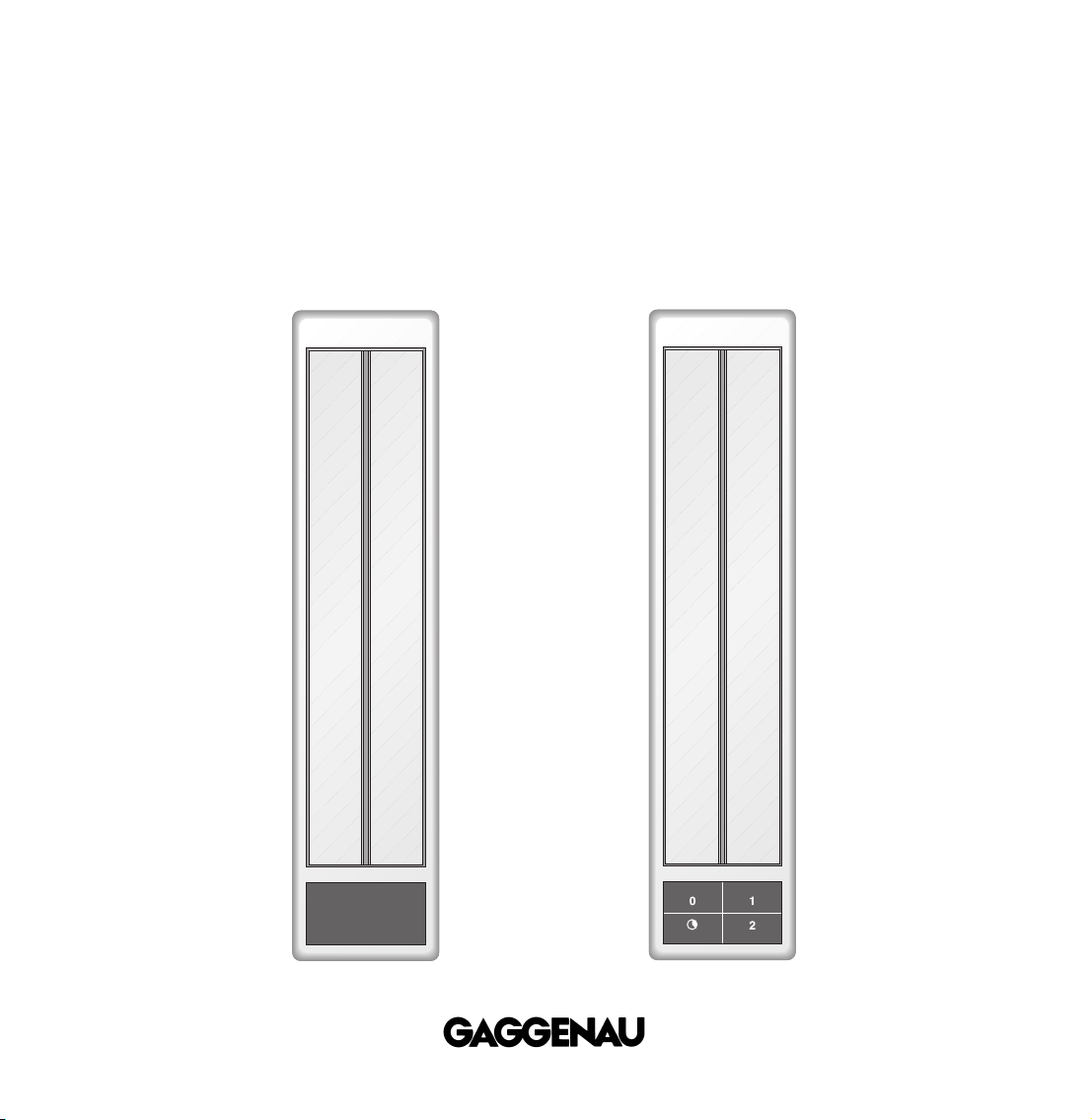
VL 430
VL 431
2
Preface
Congratulations on buying your new
“Vario” appliance.
Before switching your appliance on for the first
time, we would like you to familiarize yourself
with your new appliance. In this manual you will
find important notes on safety and operation.
These will serve to ensure your personal safety
and the lasting value of your appliance.
You will find notes on Page 4 that you ought to
observe before operating the appliance for the
first time.
The chapters entitled “Features" and “Operation"
tell you all about what your appliance can do and
how you operate it.
The chapter entitled “Cleaning and Care" gives
tips on how to keep your appliance looking good.
And now we wish you lots of fun with your
new hob ventilator.
VL 431
VL 430

3
1. Important notes
For your safety
Do not operate the appliance if it is damaged.
The appliance must only be connected by
an authorised specialist, paying attention to
the relevant regulations of the power supply
companies and the regional construction
regulations.
Observe the assembly instructions!
Make sure that connecting cables do not come into
contact with hot cooking surfaces.
Do not use to extract hazardous or explosive
substances and vapours!
As the user, you are responsible for maintenance
and proper use in the household.
Do not operate the appliance without a grease filter.
Only operate the appliance under supervision. The
appliance is intended solely for use in the
household and must not be put to any other uses.
Caution! Over-greased filters are a fire risk! Clean
the grease filter on a regular basis.
Do not clean the appliance with a steam cleaning
apparatus or with water pressure because this
poses a risk of short-circuits.
Isolate the appliance from the mains during every
maintenance operation. To do this, remove the
mains plug or actuate the corresponding fuse. If the
mains plug is not accessible, the appliance must be
disconnected from the mains by means of the
domestic fuse.
Fire risk! It is not permitted to flambé meals next
to a hob ventilator that is in operation.
Only use a grill or a deep fryer at the same time as
the hob ventilator if it is under constant supervision.
This will involve a fire risk!
Do not place any objects on the appliance; this will
interfere with the functioning of the appliance.
If you have installed a gas appliance between the
hob extractors VL 430/431, the gas hob has to be
fitted with two air baffles LS 330 on the side of the
hob while cooking. The air baffles not only improve
the airflow of the extractor next to a gas appliance,
but also prevent a flame which has been set to a
low level from being extinguished. If you have
installed the hob extractor only on one side of the
gas appliance, it is sufficient to fit one air baffle
LS 330 on the side facing the extractor.
Note: do not operate this appliance next to a
VG 411 gas cooker.
No warranty claims can be lodged in the event
of damage caused by failure to observe these
instructions.
Technical modifications reserved.

4
Operating for the first time
Before operating the appliance for the first time,
please pay attention to the following notes:
Conscientiously read through the operating and
assembly instructions before operating the
appliance for the first time.
Remove the packaging from the appliance and
dispose of it properly. Pay attention to the fact that
there are accessories in the packaging!
Keep packaging elements (e.g. plastic foil,
styrofoam parts) out of the reach of children!
Thoroughly clean the appliance before using it for
the first time. (see chapter entitled "Cleaning and
care")
Before operating the appliance for the first time,
check that the mains connection is in proper
working order.
Maintenance
The appliance must always be disconnected
from the mains when being repaired.
If the appliance does not function correctly, check
the household fuses first.
If the power supply is functioning correctly, but your
appliance still does not work, please contact your
dealer or your local Gaggenau customer service
agency. Specify the appliance type. The serial
number and type of the appliance can be found on
the rating plate.
Repairs may only be carried out by authorised
technicians, in order to guarantee the safety of the
appliance. Unauthorised tampering with the
appliance will invalidate any warranty claims.

Features
Special accessories
1 Ventilation flaps
2 Metal grease filter
3 Membrane key pad (VL 431 only)
4 Clamping screw
5 Suction extraction connection
AL 400-000 Edge trim
RV 050-150 Bifurcated pipe for joining 2 x DN 125
into DN 150
LS 330-000 Air baffle
5
2. Features
1
2
3
4
5

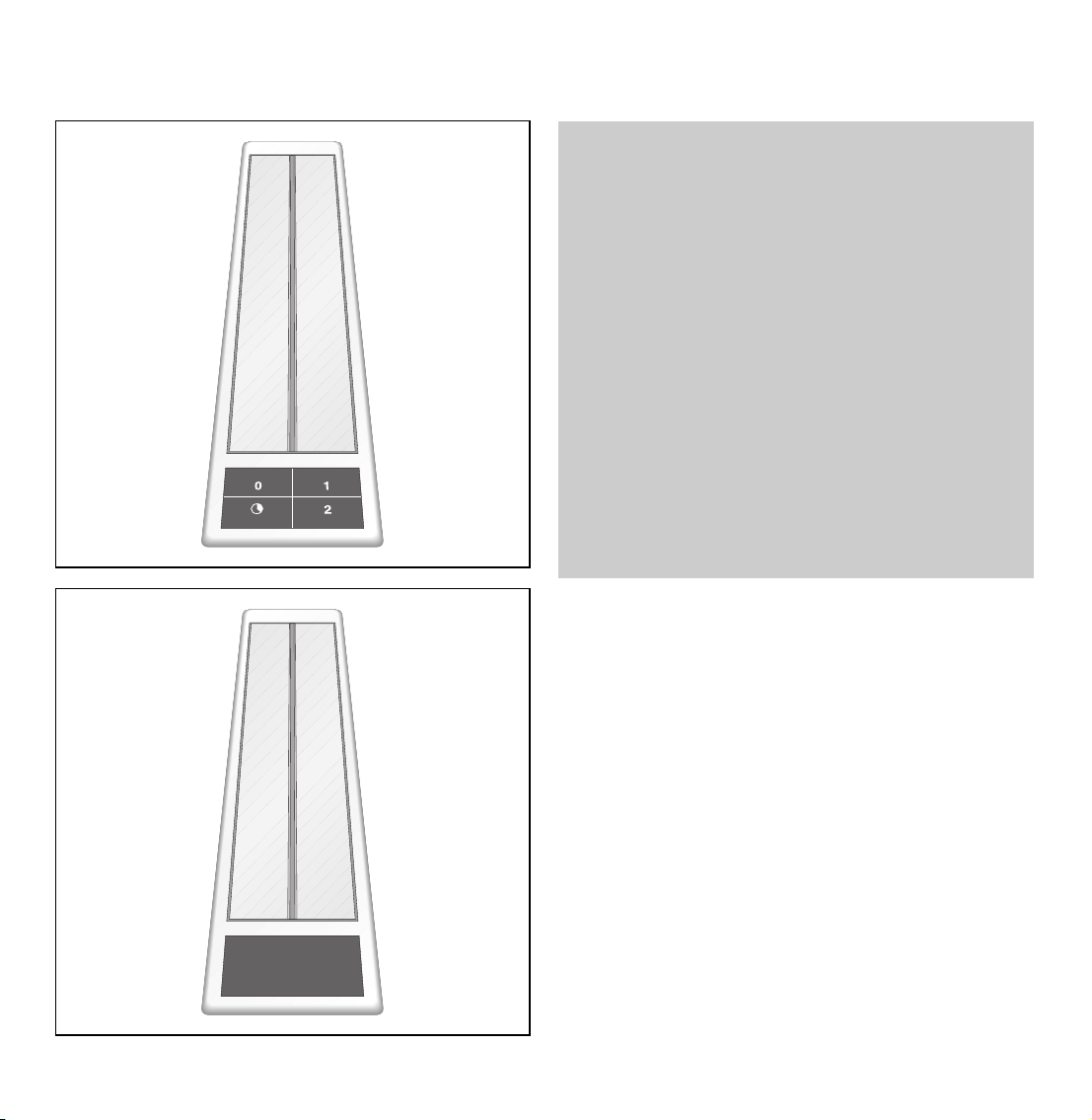
Note: VL 430 can only be operated in combination
with VL 431. All operator inputs apply to both hob
ventilators. That is to say: if you press the key for
level 1, both hob ventilators are operated
at level 1.
Switching on
Press the corresponding membrane key for the
required level. The indicator light of the chosen
level lights.
1=Low speed, the flaps open
2=High speed
= Approximately 20 minutes run-on time on
level 1. Then, the hob ventilator switches off
automatically and the flaps shut. Ideal for
ventilating the kitchen after cooking.
Switching off
Press the 0 membrane key.
The flaps shut after approx. 20 seconds.
3. Operation
6

7
Cleaning the grease filter
• Switch appliance to level 1. The flaps open.
• Push the flaps towards the front and carefully lift
them up on the rear. Then take off the flaps
upwardly.
• Turn the two retaining hooks on the sides up,
slightly push them together and remove the metal
grease filter.
You can clean the metal grease filter in a
dishwasher at a maximum temperature of 55 °C.
Place the grease filter in the dishwasher with the
opening pointing down to ensure that no food
remainders will stay on it.
Insert in the reverse order as follows:
switch appliance to level 1. Insert the grease filter
and turn the two retaining hooks down. Insert the
flap pins on the front into the hole and hook in at the
rear at the correct angle.
Cleaning the flaps
Do not clean the flaps in a dishwasher. Clean with a
moist, soft cloth.
Cleaning the frame and the membrane key pad
Apply commercially available window cleaning
agent with a soft, moist cloth. Do not spray cleaner
onto the key pad.
Note:
do not use any strong, caustic or abrasive cleaning
agents. Do not use any abrasive sponges or
brushes either.
4. Cleaning and care
The grease filters must be cleaned on a regular
basis (at the latest after 30 hours of operation).
Overgreased filters are a fire risk!

8
Important notes on installation
The appliance must only be connected by
an
authorised specialist. The specialist is
responsible for perfect functioning of the appliance
at its installation location. He must explain to the
user how the appliance can be disconnected from
the mains whenever required.
The
exhaust air can be routed into a separate
exhaust air shaft or directly into the open through
the outside wall. It is not allowed to pass the
exhaust air into a flue or exhaust air chimney that is
in operation or into a shaft that is linked to the
heating basement. Consult the chimney sweep
responsible for your district whenever you wish to
pass the exhaust air into a chimney that is not in
operation.
Adequate incoming air must be ensured if a
wood, coal, gas or oil heater or an open hearth is
operated in the same room as the one in which
the ventilator is installed.
The applicable regulations of the power supply
companies and the regional construction
regulations must be observed when installing the
hob ventilator.
Safe operation is possible whenever the partial
vacuum in the place where the firing equipment
is installed does not exceed 4 Pa (0.04 mbar).
This can be achieved whenever the air needed for
combustion is able to enter through openings that
cannot be sealed, for example in doors, windows,
incoming/exhaust air wall boxes or other technical
means.
Flexible aluminium pipes, corrosion-protected
sheet metal pipes and
exhaust air pipes whose
material conforms to fire B1 in accordance with
DIN 4102 can be used. Exhaust air pipes should
have a nominal diameter of 125 mm.
Pay particular attention to ensuring that
– the exhaust air ducts and pipes are kept as short
as possible
– the pipes are not laid at an acute angle, but as
bends and that they are inserted into the shaft at
an inclined upward angle and
– there are no cross-sectional constrictions in the
upward direction (this reduces the volume flow).
To prevent the ingress of water, e.g. condensate or
rain water from an uncovered exhaust air shaft, our
condensate separator RV 050-150 must be installed
in the proximity of the hob ventilator. The
condensate separator must still be accessible after
installation.
Technical modifications reserved.
5. Assembly instructions

9
Installing the appliance
If two Vario appliances are used, the hob ventilator
must be installed between the appliances. If 4-plate
hobs are used, it is recommended to place two
ventilators to the left and right of the hob. Owing to
the high air output, an adequate supply of air is
required. If you have installed a gas appliance
between the hob extractors VL 430/431, the gas
hob has to be fitted with two air baffles LS 330 on
the side of the hob while cooking. The air baffles
not only improve the airflow of the extractor next to
a gas appliance, but also prevent a flame which has
been set to a low level from being extinguished.
If you have installed the hob extractor only on one
side of the gas appliance, it is sufficient to fit one
air baffle LS 330 on the side facing the extractor.
Note: do not install this appliance next to a
VG 411 gas cooker.
The hob ventilator is installed at the side of the
Vario appliance without any gap between the
appliances.
• As standard, the blow-out direction is downward.
Proceed as follows to establish a blow-out opening
at the side:
– Undo all 5 screws on the connection piece and
detach the connection piece.
– Undo the screws of the side cover.
– Screw the connection piece onto the side
opening and the cover onto the bottom opening.
• Cut out the recess for one or several Vario
appliances in your worktop. Proceed as indicated
on the installation sketch.
• Peel the protective film off the sealing tape. Stick
the sealing tape to the front and rear of the cut
out, so that half of the tape overlaps on the inside.
• On the side of the ventilator, press the seal into
the groove provided.
Blow-out opening:
downward or
at the side
93
450
510
140
80
820
128 0
85
50
162
min. 35
min. 50
490
Ø 125
140
135

10
• Turn the clamping screws to the side. Insert the
appliance with the control panel on the front into
the cut-out and align it.
Note: do not stick the appliance onto the worktop
with silicone.
• Turn the clamping screws under the countertop
and tighten them evenly. Do not tighten the
clamping screws too tightly, as a uniform sealing
gap should be left all round.
• Connect the appliance to the fan module by
means of a flexible aluminium pipe with a
diameter of 125 mm.
• Connect the appliance to the fan module by
means of the 4-pole plug.
We recommend the use of our telescopic wall box
TM 180-043 to route exhaust air through the outside
wall.
Installing the edge trim AL 400-000
The edge trim has to be fitted to the side of the hob
ventilator, if this ventilator is installed together with
other Vario appliances and forms the left or right
edge of this combination.
The edge trim does not change the total width of
the cut-out, however, the width of the edge trim has
to be added to the total width of the appliance
combination.
Simply press the edge trim under that side of the
ventilator, that forms the edge of the combination.
The hooks on the side of the edge trim will latch
into the openings provided on the hob ventilator.

Electrical connection
Pay attention to the rating plate data.
Observe the connecting scheme when connecting
the hob ventilator and the fan module.
9000029649 en 12.04 EB 11
Connectors VL 431
connecting
cable to GB
connecting cable
to VL 430


GAGGENAU HAUSGERÄTE GMBH
CARL-WERY-STR. 34 · D-81739 MÜNCHEN
Y (0 89)45 90-03
FAX (089) 45 90-23 47
www.gaggenau.com
 Loading...