

Page 1
Operating and assembly instructions
VG 231
Gas cooker
Page 2

1
Preface
1. Important notes Page 3-4
1.1 For your safety Page 3
1.2 Operating for the first time Page 3
1.3 About use Page 4
2. Structure and operating principle Page 5-6
2.1 Structure Page 5
2.2 Special accessories Page 5
2.3 Operating principle Page 6
3. Operation Page 7
4. Cleaning and care Page 8
5. Maintenance Page 9
5.1 General Page 9
5.2 Remedying slight malfunctions yourself Page 9
6. Technical data / Table Page 10
7. Practical tips Page 11-12
7.1 Accessories Page 11
7.2 Cooking in the wok Page 11
7.3 Recipes Page 12
8. Assembly instructions Page 13-18
8.1 Important notes Page 13
8.2 Gas connection / electrical connection Page 14
8.3 Nozzle replacement Page 15-17
8.4 Installing the appliance Page 18
VG 231
Page 3
2
Cooking with your new gas hob will be even
more fun than before.
The appliance offers you the following
advantages:
– Regulation from hot to cold in seconds
– High safety standard thanks to thermal
protection elements for the burner
– Thanks to the novel installation method
implemented, installation is child's play!
To ensure that you will be able to use this
appliance in all its diversity, read through
the operating and assembly instructions
conscientiously before operating it for the first
time. The instructions contain important notes on
use, installation and maintenance of the appliance.
You will find notes on page 3 that you ought to
observe before operating the appliance for the
first time.
The chapters entitled “Structure and operating
principle" and “Operation" tell you all the
things your cooker is capable of doing and how to
operate the appliance.
The chapter entitled “Cleaning and care" will
make sure that your appliance will stay operable
and beautiful for a long time.
And now we wish you lots of fun cooking!
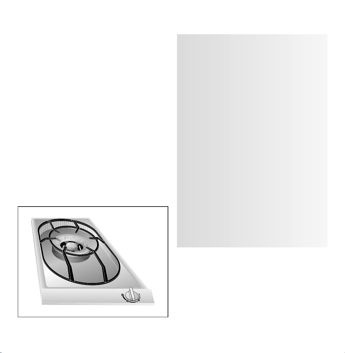
Preface
Fig. 1
Page 4

1.1 For your safety
You must not operate the appliance if it is damaged.
When connecting electrical appliances in the pro-
ximity of the appliance, make sure that connecting
leads do not come into contact with hot cooking
surfaces!
As the user, you yourself are responsible for
maintenance and proper use in the household.
Only ever operate the appliance under supervision.
Make sure that the burner parts are correctly fitted.
The appliance must only be operated with a wok, a
pot or a pan on a ring.
Note:
If you have fitted the appliance cover VD 201-010
(special accessory) on the appliance, it must not be
closed until the appliance has cooled down
completely. Do not operate the appliance with the
cover closed! Heat development may damage the
appliance and the cover. Do not use the appliance
cover as a surface for placing objects or for
keeping things warm.
Important: the appliance heats up during
operation. Keep children away
Do not clean the appliance with a steam cleaning
apparatus or with water pressure – risk of short-
circuits!
Isolate the appliance from the mains during every
maintenance operation. To do this, remove the
mains plug or actuate the corresponding fuse.
Close the gas supply.
Repairs must be carried out by authorised
specialists, thus ensuring electrical safety.
No warranty claims can be lodged for any damage
resulting from failure to observe these instructions.
Observe caution with oils and fats. They may
overheat and burn easily. Foodstuffs that are
prepared in fat and oil (e.g. French fries) must only
be prepared under constant supervision!
Technical modifications reserved.
1.2 Operating for the first time
Before operating the appliance for the first time,
please pay attention to the following notes:
The appliance must only be connected by an
authorised specialist.
Read through these instructions attentively before
operating the appliance for the first time.
Note:
The rating plate for this appliance is included on
a separate sheet. Keep the rating plate in a safe
place along with your operating and assembly
instructions.
Remove the packaging from the appliance and
dispose of it properly.
Keep packaging elements away from children.
Thoroughly clean the appliance and accessories
before using them for the first time. This will
eliminate any “newness" smells and soiling (see
chapter entitled “Cleaning and care").
3
1. Important notes
Page 5

1.3 About use
The appliance is intended solely for use in the
household and must not be put to any other uses.
Use the appliance to prepare meals only. It must not
be used to heat up the room in which it is installed.
Use of a gas cooker generates heat and humidity
in the room where it is installed. This is why
attention must be paid to good kitchen ventilation.
Ventilation openings must be kept unobstructed.
Prolonged use of the appliance may call for
additional ventilation such as opening a window or
a door, or stronger air extraction by an extractor
hood.
To guarantee good combustion, the room in
which the appliance is installed must have a
minimum volume of 10 m
3
and must possess a
door that opens outdoors or a window that can
be opened.
Do not operate the cooking position without a pot
or a pan or a wok placed on it. Do not heat up any
empty pots or pans; this may result in a build-up
of heat. Use pots and pans with thicker bottoms
because heat distribution is particularly improved
in the low setting. The better the size of pots and
pans is adapted to the burner size, the better the
heat of the gas flame will be exploited and the
more costs will be saved.
It is not permitted to use grilling stones because the
resulting build-up of heat may damage the
appliance.
Switch the burners to the low setting whenever you
remove pots or pans briefly, thus saving gas and
reducing pollution.
Whenever the gas hob is fitted under a vapour
extractor hood, always cover the rings with pots
or pans. Otherwise, parts of the vapour extractor
hood may become damaged by the extreme heat
development or grease residues in the filter may
ignite. Ensure an adequate supply of air when using
a vapour extractor operating in the exhaust air
mode.
After igniting, keep the control knob pressed for
around 5-8 seconds more. The thermal sensor
must be heated for 5-8 seconds before the knob
can be released.
In the event of a power failure, you can also
ignite the unit with matches or any other ignition
aid. The thermal protection facility that prevent gas
from flowing out in the open position functions
without restriction.
Pots with a diameter of less than 100 mm or more
than 320 mm should not be used. When using
larger pots, pay attention to keeping to a minimum
distance of 100 mm between the cooking vessel
and combustible surroundings. A minimum distance
of 15 mm must be observed between the control
knob and the pot or pan.
In the event of malfunctions, contact your
specialist dealer or your responsible Gaggenau
after-sales service.
Tip: when buying pots, pay attention to the fact that
the manufacturer frequently specifies the top pot
diameter, which is generally larger than the
diameter of the base.
Observe the manufacturer's specification! Use
cooking utensils that the manufacturer states as
being “suitable for gas".
4
Page 6
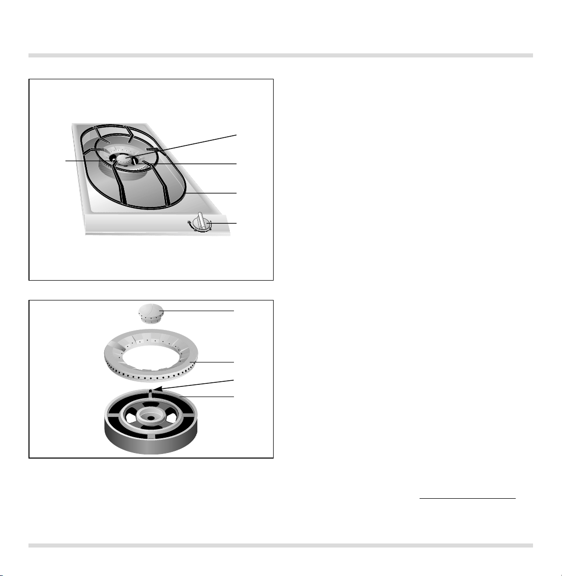
2.1 Structure
2.2 Special accessories
1 Spark plug for automatic ignition
2 Wok burner 0.25 - 5 kW
3 Thermal fuse for flame monitor
4 Pot support
5 Control knob for the cooking position
6 Burner cover
7 Burner ring
8 Burner head recess
9 Burner head
You can order the following special accessories:
– VV 200-000: connecting trim
– VD 201-010: appliance cover
5
2. Structure and operating principle
Fig. 2
Fig. 3
6
7
8
9
3
5
4
2
1
Page 7

2.3 Operating principle
The appliance features one-hand operation. That is
to say, the ignition is activated when the control
knob is pressed briefly.
After igniting, keep the control knob pressed for
around 5-8 seconds more because the heat sensor
that opens the gas channel has to warm up first.
The burner has a thermal protection device that
prevents unburned gas from escaping in the open
position.
The total rated thermal load amounts to:
5.0 kW referred to Hs* (gross calorific value)
4.5 kW referred to Hi(calorific value)
The specified rated load is defined by installation
of the fixed nozzles.
The gas hob is converted to a different gas type
by nozzle replacement (full and low-burning
nozzles) (see nozzle table).
The symbols on the control panel mean:
0 Off
High position of outer and inner flame rings
Low position of outer flame ring
High position of inner flame ring
Outer flame ring off
High position of inner flame ring
Outer flame ring off
Low position of inner flame ring
The flame is infinitely variable between high and
low-setting.
6
Page 8

The cooking positions must only be ignited
when all burner parts are fitted. Otherwise,
malfunctions may occur on the ignition unit.
Switching on (Fig. 4):
– Place a pot or a pan on the corresponding
cooking position.
– Press in the control knob fully and keep it
pressed. This activates the ignition.
– Turn the control knob to the left to the
“high" position.
If the flame should not ignite within 2 to 4 seconds,
turn the control knob further to the left to the
“low" position and then back to the “high"
position after ignition. It is often faster to ignite in
the low position because the various gases have a
differing ignition response.
Once the flame is burning, keep the control knob
pressed for another 5-8 seconds. The thermal
sensor must be heated for 5-8 seconds before the
knob can be released.
Repeat the operation if the flame should go out
again.
The flame size can be set continuously between full
and low by slowing turning the control knob.
Switching off (Fig. 5):
Fully turn the control knob to the left to the 0
position on the left.
7
3. Operation
Fig. 4
Fig. 5
Page 9

Wipe off spilt food immediately, thus ensuring that
it cannot burn in on the hob.
Caution! The burner gets very hot during
operation!
Never use abrasive or caustic cleaning agents.
Keep the air inlet openings on the rear of the
panel unblocked and clean.
You should only clean the control panel and the
control knobs with detergent and a a soft cloth.
To ensure perfect functioning, keep the thermal
sensor and the spark plug clean.
Please thoroughly clean the appliance before
operating it for the first time and after every
use.
– Wait until the appliance has cooled down.
– Remove the pot grid.
– Remove the burner cover and the burner ring.
– Clean the hob, the burner covers and the pot
grid with commercially available cleaning
agents (not in a dishwasher!), e.g. with warm
soap solution and a dishwashing brush.
– Whenever required, clean the burner head with
a moist cloth.
– Soak burnt-in remainders in a little water and
detergent. This loosens even the most stubborn
of soiling. Do not use any abrasive agents and
abrasive sponges.
– As the result of heat development, slight dis-
coloration can appear on the stainless steel
surface. Do not attempt to scrape away such
discoloration. This damages the surface.
Distribute stainless steel care agents uniformly
and thinly on the hob (not on the control panel!).
This will ensure an even surface and will keep
your hob in a good condition for a long period of
time.
When assembling the appliance (Fig. 6), make sure
that the burner head (5) is placed on the burner
base (7) in such a way that the twist protector (4) is
held in place by the thermal element (6). Place the
burner ring (2) on the burner head (5) from above.
The locking lug on theunderside of the burner ring
must fit in the recess (3). Place the burner cover (1)
in the centre of the burner head. Fit the pot support.
4. Cleaning and care
Caution:
Never use high-pressure or steam jet units to
clean your appliance because otherwise the
electrical safety of the appliance will no longer be
guaranteed.
8
Fig. 6
1
2
3
5
4
6
7
Page 10

5.1 General
5.2 Remedying slight malfunctions
yourself
In the event of malfunctions, check whether the
gas and electricity supply is in proper working
order, i.e. the gas valve is open and the plug has
been plugged into the socket.
If the power supply is functioning correctly, but your
appliance still does not work, please contact your
dealer or your local Gaggenau customer
service agency. Specify the appliance type (see
rating plate).
Repairs may only be carried out by authorised
electricians, in order to guarantee the safety of
the appliance.
Unauthorised tampering with the appliance will
invalidate any warranty claims.
Only ever use original spare parts.
9
5. Maintenance
Fault Remedy
The burner does not ignite after several attempts. Check whether ...
... the burner is correctly assembled.
... the gas shut-off facility is open.
... the burner is clean and dry.
... the domestic fuse has tripped.
If necessary, inform after-sales service.
The gas flame goes off after ignition. Check whether ...
... the burner cover and the burner ring are
correctly fitted.
... the flame has been extinguished by a strong
draught in the room.
The cooking ring burner's electrical Check whether there are food remainders
igniter is no longer functioning. between the ignition electrode and the burner
cover. Carefully remove these.
The flame tips are yellow and not blue. Check whether the burner is dry and clean.
Page 11

10
Technical data (gas)
Burners: super strong burner
Stage 4 full flame 5.0 kW
Stage 3 small outer flame
plus stage 2 full inner flame 1.0 kW
Stage 2 full inner flame < 0.50 kW
Stage 1 low flame < 0.25 kW
Gas connection:
R 1/2’’ union nut for R 1/2’’ bracket to DIN 1999,
conical-cylindrical
Technical data (electrical)
Rated consumption 0.8 W
Voltage 220 - 240 V
Frequency 50 - 60 Hz
Technical modifications reserved.
6. Technical data / Table
Countries AT BE CH DE BE FR LU NL DE BE CH DK ES AT DE
DK ES FI FR FI FR GB GR
GB GR IE IS IE IS IT LU
IT LU NL PT NL NO PT SE
SE
Gas family Natural gas Natural gas Natural gas But/Prop But/Prop
Gas type H / E (G 20) L (G 25) LL (G 25) 3 + (G30/31) (G30/31)
Pressure 20 mbar 25 mbar 20 mbar 28-30/37 mbar 50 mbar
Nozzle, full burn, outer 1.55 1.55 1.73 1.00 0.87
Nozzle, low burn, outer 0.75 0.75 0.84 0.51 0.45
Nozzle, full burn, inner Nr. 34 Nr. 34 Nr. 44 Nr. 13 Nr. 7
Nozzle, low burn, inner 0.41 0.41 0.45 0.27 0.25
Air gap adj /outer [mm] 22222
Air gap adj /inner [mm] 33366
∑ Power 5 kW 5 kW 5 kW 5 kW 5 kW
∑ Consumption 0.48 m
3
/h 0.55 m3/h 0.55 m3/h 364 g/h 364 g/h
Page 12

7.1 The wok and accessories
(not included in the scope of delivery)
– The “original wok" is the ideal wok for your gas
cooker.
– The wok looks like a hollow semisphere with a
long handle or wooden handle. It has a rounded
base and slanted sides. The thin steel passes the
heat swiftly to the inside, but soon cools down
again as soon as the flame is set to a lower
setting. Therefore, ingredients cannot overcook.
– The diameter is between 35 and 40 cm for
4 persons.
– Woks may consist of various materials. Cast-iron
woks are more stable and keep the heat longer.
– They have a round, high cover. Therefore, they
are also capable of steaming and stewing.
– The semicircular grid is hooked in on the edge of
the wok. On it, you can steam ingredients, you
can allow deep fried foods to drip or you can
keep browned foods warm.
– Use the chan (rounded spatula) or the wooden
pan reversing implement.
– Use a ladle to remove foods.
– Use the strainer to lift deep fried foods from the
fat or large pieces out of a sauce.
– You can use bamboo baskets for steaming.
7.2 Cooking in the wok
You can fry, steam, deep fry, stew and cook normally.
Stir frying is the special cooking method for the
wok. Ingredients cut into small pieces are cooked
as briefly as possible under strong heat and
constant stirring. In the large, round pan everything
can be stirred and turned faster and with greater
ease than in a conventional frying pan. Thanks to
stirring, ingredients do not burn onto the pan.
Surplus oil drains off towards the middle. In next to
no time, you obtain delicious roasted foods, the
pores in meat close and fish becomes nices and
juicy. Vegetables stay crispy, and aromas and
healthy vitamins are retained.
Important: the cooking time is so short that all
ingredients should be ready for cooking before you
begin. The correct sequence is also important. First
place the ingredients with the longest cooking time
in the wok. For example, these are hard-fibred
vegetables such as carrots. Soft vegetables such as
mushrooms or sprouts are added later.
Proceed as follows:
– Pour sufficient oil into the wok to coat the surface.
We advise you to use peanut or or soya oil.
– Heat up the oil to just before the smoking point;
only then begin with stir frying.
– Cut the food into pieces of equal size, but not too
small, thus making sure they will not burn.
– If you are cooking larger quantities, work with
portions as otherwise not all of the food will reach
the hot base of the wok.
– Meals that are ready ca be kept warm on a
minimal flame. Clean the wok after every use and
rub its inside with oil. This will prevent rusting.
11
7. Practical tips
Page 13

7.3 Recipes
Beef in oyster sauce
Ingredients for 4 persons
500 g fillet of beef
1/2 teaspoon of black pepper (freshly ground)
2 tablespoons of dark soya sauce
1 tablespoon of wheat flour
5 dried Tongku mushrooms
300 g of oyster mushrooms
2 spring onions, 1 fresh red chili
4 cloves of garlic
1 thumb-sized piece of fresh ginger
3 tablespoons of oyster sauce, 1 tablespoon of fish
sauce
1 teaspoon of sugar, 4 tablespoons of rice wine
– Rinse the meat in cold water, dab it dry, remove
tendons and skin, and cut it into approximately
1 cm cubes. Mix with pepper, soya sauce and
flour and then marinate the mixture, covered up,
for about one hour in the fridge.
– In the meantime, wash the Tongku mushrooms.
Soak them in hot water for about 20 minutes.
– Clean the oyster mushrooms. Rinse them briefly
in running water and cut them into large pieces.
– Wash the spring onions and cut them in half
alongsides. Cut the spring onions into
approximately 3 cm long pieces. Wash the chili
and cut it in half alongside, remove the base of
the stalk, remove the pips and cut it into strips.
– Wash you hands thoroughly!
– Peel the garlic and ginger and chop it up finely.
– Carefully squeeze out the Tongku mushrooms
and quarter them.
– Heat oil in the wok. First singe the meat in
portions, stirring it at the same time. Briefly roast
the garlic and ginger and add the meat cubes.
Reduce the heat. Add the Tongku and oyster
mushrooms, spring onions, oyster and fish sauce
and the sugar and allow to cook for about 2 min-
utes in medium heat.
– Add the chili strips and allow them to heat up. Stir
in the rice wine. Garnish the meal with the chili
strips.
Chicken in basil and tomato sauce
Ingredients for 4 persons
100 g of shallots
500 g of fillet of chicken breast
750 g of tomatoes
1 large bunch of basil
2 tablespoons of oil
200 g of crème fraîche
salt
freshly ground black pepper
– Peel the shallots and cut them into cubes. Rinse
the fillets of chicken breast in cold running water
and cut them uniformly into cubes.
– Score the tomatoes and place them briefly in
boiling water or steam. Lift them out and skin
them, then chop them into coarse cubes.
– If necessary, rinse the basil and shake it well to
dry it, and then place a few leaves aside for
garnishing. Cut or chop the others.
– Heat up the oil in the wok. While constantly
stirring, singe the chicken meat in portions and
remove it from the wok. Briefly roast the shallots
until they are glassy. Add the meat.
– Add the chopped tomatoes and the crème fraîche
to the wok. Stir all ingredients and spice them
with the finely cut basil, salt and pepper. While
stirring, simmer for a few minutes.
– Season the sauce with salt and pepper and serve
the dish garnished with basil leaves.
Tip: if necessary, add to wine to the sauce to
improve taste.
12
Page 14

8.1 Important notes
Please observe the safety notes and the
important notes (Chapter 1).
The installing technician is responsible for
perfect functioning of the appliance at its
installation location. He must explain the operating
principle to the user with reference to the operating
instructions and must show how to switch of the
electricity and gas whenever required.
Caution:
Before connecting the appliance, please check
whether the local connection conditions such as
the gas type, gas pressure and mains voltage and
the appliance settings are correct. Refer to the
adhesive label on the gas connection or the rating
plate for the necessary information. This gas hob
conforms to the categories that are specified on
the rating plate. The rating plate can be found on
the appliance and additionally on the enclosed
addendum sheet. By replacing nozzles, it is
possible to set the appliance to any gas listed on
the rating plate. If the data should not agree, the
appliance must be set to the required gas type and
the available pressure.
As this gas hob is not intended for connection to an
exhaust gas system, pay attention to the applicable
installation conditions.
Note on ventilation:
To ensure good combustion, the room in which this
appliance is installed must have a minimum volume
of 10 m
3
and a door that opens out to outdoors or a
window that can be opened.
In Germany
, the gas hob must be installed and
connected by a fitter who has been approved by
the gas supply company. At the same time, the
guidelines such as DVGW-TRGI 86 and TRF 1988
and the regulations of the gas supply companies
and of the responsible authorities must be
observed.
In Switzerland
, the respectively applicable
regulations of SVGW and of the Association of
Cantonal Fire Insurance Companies as well as the
manufacturer's installation conditions must be
observed when installing the appliance.
In Austria
, the ÖVGW-TR Gas (G1) and ÖVGW-TR
Flüssiggas (G2-Part 1) regulations and the local
construction and trade regulations must be
observed when installing the appliance.
The appliance may be installed in kitchen
combinations made of wood or similar combustible
materials without taking additional measures. The
rear wall must consist of non-combustible material.
A minimum distance of 150 mm from heat-sensitive
items of furnishing or contact surfaces (cupboard
side panel) must be observed.
The hob conforms to appliance class 3 and must be
installed in the worktop as shown in the installation
sketch.
The distance between the suspended cupboard
and the worktop must be at least 600 mm. Attention
must be paid to the manufacturer's specified safety
clearance when a vapour extractor is installed. Wall
trims must be heat-resistant, and the minimum
distance between the hob and the wall trim is at
least 35 mm.
After unpacking, check the appliance for any
transportation damage and report this immediately
to the transportation company.
Technical modifications reserved.
13
8. Assembly instructions
VG 231-... FDxxxx
AC 220-240V 50/60Hz Qn 5,0 kW
0,8 VA
Page 15

14
8.2 Connecting the appliance
8.2.1 Gas connection
8.2.2 Electrical connection
Gas connection
The gas connection
must be in a location that
permits access to the shut-off valve and which, if
applicable, is visible after opening the door of the
furniture item.
By means of the included R 1/2” connection bracket
(on the appliance end) with the affiliated washer,
the appliance must be connected to a fixed
connecting line or a gas safety hose to DIN 3383
Part 1 that corresponds to the type concerned.
An ambient temperature of 70 °K must not be
exceeded if the gas safety hose consists only partly
of metal. The permissible ambient temperature for
a gas safety hose that consists completely of metal
is 115 °K.
If a flexible line is used, it must be laid in such a
way that it cannot come into contact with moving
parts of the kitchen element (e.g. drawer).
Electrical connection
Electrical connection (AC 220-240 V) is established
by means of a connecting cable with an earthing
contact plug connected to an earthed socket, which
must also be accessible after installation of the gas
hob.
If, after installation of the gas hob, not all poles can
be isolated from the mains by removing the plug,
an isolating device with a contact gap of at least
3 mm must be permanently installed. When
establishing connections, make sure that the
connecting lead cannot come into contact with hot
parts of the gas hob or other hot parts.
If damaged, the mains cable must be replaced by
a special mains connecting cable. The mains
connecting cable must only be connected by the
manufacturer or the manufacturer's after-sales
service.
The mains connecting cable must at least
correspond to the type H05-VV-F-3G 0.75.
40
103
Fig. 7
Seal
1/2”
Page 16

8.3 Nozzle replacement
Changing over to a different gas type
Only authorised specialists are permitted to
change over to a different gas type. The nozzles
needed for the gas type to be set are available as a
conversion kit. Please specify the appliance type
and the required gas type.
– Disconnect the appliance from the power
supply.
– Remove the pot support, the burner ring, the
burner cover and the burner head.
– If the appliance is connected rigidly to a gas
main, it must be disconnected from the gas
network. If it is connected via a gas safety hose,
the appliance only needs to be pushed out of its
mount from below and taken out of the worktop.
– Undo the securing nut (SW 11) of the
thermocouple and the two securing screws that
become visible under the detached burner head
(Fig. 8).
– Remove the hob.
– Pull off the control knob. After undoing the
securing screws (1) on the left and right (Fig. 9),
you can remove the control panel by lifting (2)
and pushing (3) it out of the latch (Fig. 10).
15
Fig. 9
Fig. 10
2
1
3
Fig. 8
Page 17

16
Replacing the low setting nozzles (Fig. 11)
The low setting nozzles for the inner (2) and outer
(1) burners are located in the gas valve. They must
be replaced according to the new gas type and as
specified in the low setting nozzle table. Screw in
the nozzles fully and check that they are tight
(metallic seal).
If it should be necessary to correct the low-setting
nozzles (1) and (2) as the result of deviating gas
types and pressure, the flow rate can be increased
by turning to the left.
Replacing the main nozzles
Main nozzle replacement for the outer burner
(Fig. 12)
Replace the main nozzle (3) (SW 10) for the high
setting according to the new gas type and as
specified in the nozzle table. Beforehand, loosen
the screw (2) and push away the air regulation
sleeve (1) and fix it in place with the screw (2).
Check the absence of gas leaks on the installed
main nozzle. According to the new gas type, stick
the included adhesive label over the data specified
on the gas connection.
Adjust the air gap according to the table entitled
“Air gap adjustment" for the outer burner.
Main nozzle replacement for the inner burner
(Fig. 13)
Remove the supply line by undoing the union nut
(4) (SW 8). Unscrew the injector screw (5) (SW 12)
and, using a small screwdriver, remove the nozzle
(6) from the injector (7). Install the nozzle
according to the new gas type (see data in the
nozzle table). To do this, fit the nozzle (6) on the
front of the injector screw (5) and screw both of
them into the injector. Plug in the supply line and
screw it in. Check for the absence of leaks. Adjust
the air gap as detailed in the table entitled “Air gap
for inner burner".
Fig. 13
distance in mm
Fig. 12
1
2
3
4 5 6 7
See table on Page 10 for details of nozzle settings.
Fig. 11
2
1
Caution: the flame must neither go off nor flash
back when you change over swiftly from the high
to the low setting.
Page 18

17
First air regulation
First air regulation may be necessary to always
achieve a stable and low-noise flame in the event of
deviating gas types and pressures.
First air regulation for outer burner (Fig. 14)
After undoing the screw (2) (7 mm), move the air
regulation sleeve (1) in the direction of the nozzle
(3)or away from the nozzle up to a maximum
distance of 12 mm until the flames burn stably and
with low noise. Yellow tips must not be visible in the
flames. The flame must not go off when you switch
swiftly from the high to the low setting. Firmly screw
in the screw (2) again.
First air regulation for outer burner (Fig. 15)
The throttle spring (4) is generally positioned on
the hexagon shaft. If required, shift the throttle
spring. For exact details, refer to the table entitled
“Air gap for inner burner". The air gap must
never be entirely sealed off.
Air gap
Fig. 15
See table on Page 10 for details of nozzle settings.
distance in mm
Fig. 14
1
4
2
3
Page 19

8.4 Installing the appliance
– Produce the recess for one or several Vario
appliance(s) in your worktop. Proceed as
indicated on the installation sketch and the
dimension table. The dimension table contains
details of the space requirement for the trim
between the appliances.
Important: the angle between the cut surface
and the worktop must amount to 90° (Fig. 16).
– Mark the centre of the recess exactly. Secure
the securing rails on the front and rear edges of
the recess. Make sure that the lugs of the securing
rails lie on the worktop and that the centre
marking of the securing rails is precisely flush
with the centre marking on the worktop (Fig. 17).
– Lower the appliance into the worktop. Make
sure that the engaging lugs on the appliance lie
exactly on the clamping springs. Press the
appliance firmly into the worktop. The engaging
lugs on the appliance “snap" into the clamping
springs (Fig. 18).
Note: When installing the appliance in granite or
marble worktops, have the holes produced by a
specialist or stick on the securing rails with a
temperature-resistant 2-component adhesive (metal
on stone).
18 5080003239ind02 en 11.04 SK
Note:
Several appliances can also be installed in
individual recesses, as long as a minimum
clearance of 40 mm is kept to between the
appliances.
1
,
4
m
8
8
8
,
5
2
8
8
510
490
1
1
4
7
8
5
4
5
6
1
268
min. 35
min.
50
4
2
,
5
Fig. 17
Fig. 16
Fig. 18
Secure the cover on the appliance before
installation. See assembly instructions
VD 201-010.
 Loading...