

Page 1

Montageanleitung
Installation Manual
Notice de pose
Istruzioni per il montaggio
CG 492
Gaskochmulde
Gas Cooker
Plaque de cuisson à gaz
Piano di cottura a gas
Page 2

Page 3

DE - Montageanleitung 2-12
Wichtige Hinweise 2
Belüftungshinweis 3
Elektrischer Anschluss 3
Einbaumaße 4
Hinweise für Einbau in
Edelstahl-Arbeitsfläche 5
Vorbereiten des Einbaumöbels 6
Bohrungen in der Frontblende 7
Einbau der Kochmulde 8
Montage der Achsen 9-10
Silikon verfugen 11
Gasanschluss 12
EN - Installation Instructions 13-23
Important Notes 13
Note on Ventilation 14
Electrical Connection 14
Measurements 15
Notes for Installation in a Stainless Steel
Worktop 16
Preparing the Cabinet 17
Drilling the Holes in the Cabinet Front 18
Installing the Cooker 19
Installing the Spindles 20-21
Silicone Sealing 22
Gas Connection 23
FR - Notice de pose 24-34
Remarques importantes 24
Aération 25
Raccordement électrique 25
Cotes d’encastrement 26
Instructions en cas de pose dans un plan
de travail en inox 27
Préparation du meuble 28
Perçages du bandeau avant 29
Pose de la table de cuisson 30
Montage des axes 31-32
Faire les joints en silicone 33
Branchement du gaz 34
IT - Istruzioni per il montaggio 35-45
Indicazioni importanti 35
Indicazione per la ventilazione 36
Allacciamento elettrico 36
Misure di incasso 37
Note per il montaggio in piani di lavoro di
acciaio inox 38
Preparare il mobile da incasso 39
Fori nel pannello frontale 40
Montaggio del piano di cottura 41
Montaggio degli assi 42-43
Applicare il silicone 44
Allacciamento del gas 45
Page 4
Bitte beachten Sie die Sicherheitshinweise und
wichtigen Hinweise.
Der Installateur ist für das einwandfreie
Funktionieren am Aufstellungsort verantwortlich.
Er muss dem Benutzer die Funktionsweise anhand
der Bedienungsanleitung erklären und darauf
verweisen, wie im Bedarfsfall Elektro und Gas
abgeschaltet werden können.
Nach dem Auspacken überprüfen Sie das Gerät
ggf. auf Transportschäden und melden Sie dies
umgehend dem Transportunternehmen.
Achtung:
Vor dem Anschluss des Gerätes prüfen Sie bitte, ob
die örtlichen Anschlussbedingungen, wie Gasart,
Gasdruck und Netzspannung und die Geräteeinstellung, übereinstimmen. Die notwendigen
Informationen entnehmen Sie dem Aufkleber am
Gasanschluss oder dem Typenschild. Diese GasKochmulde entspricht den Kategorien, die auf
dem Typenschild aufgeführt sind. Das Typenschild
befindet sich auf dem Gerät und zusätzlich auf
dem beiliegenden Zusatzblatt. Durch Düsen wechsel ist es möglich, jedes dort aufgeführte
Gas einzu stellen. Sollten die Daten nicht überein stimmen, so muss das Gerät auf die benötigte Gasart
und den vorhandenen Druck umgestellt werden.
Da diese Gas-Kochmulde nicht für den Anschluss
an eine Abgasführung vorgesehen ist, beachten
Sie die geltenden Installationsbedingungen.
Das Gerät darf ohne zusätzliche Maßnahmen in
Küchenkombinationen aus Holz oder ähnlichem
brennbarem Material eingebaut werden.
Gebäudeseitig muss die Wand hinter dem Gerät
aus nicht brennbarem Material bestehen.
Zu wärmeempfindlichen Möbelteilen oder
Anstellflächen (Schrankseitenwand) muss ein
Mindestabstand von 300 mm eingehalten werden.
Die Kochmulde entspricht der Geräteklasse 3 und
muss gemäß der Einbauskizze in die Arbeitsplatte
eingebaut werden.
Der Einbau unter einem Hängeschrank ist nicht
gestattet. Bei Einbau unter einer Dunstabzugshaube
ist ein Mindestabstand von 760 mm einzuhalten.
Wandabschlussleisten müssen hitze beständig sein,
der Mindestabstand zwischen Mulde und
Wandabschlussleiste beträgt 35 mm.
Der Einbau und der Anschluss der Gas-Kochmulde
muss von einem beim Gasversor gungs unternehmen
zugelassenen Installateur unter Beachtung aller
gültigen Vorschriften vorgenommen werden.
In Deutschland
muss der Einbau und der Anschluss
der Gas-Kochmulde von einem beim Gasversor gungs unternehmen zugelassenen Installateur
vorgenommen werden. Dabei sind die Richtlinien,
wie DVGW-TRGI 2007 und TRF 1997 sowie die
Vorschriften der Gasversorgungsunternehmen
und der zuständigen Behörden zu beachten.
In der Schweiz
sind bei der Aufstellung und
Installation folgende Vorschriften zu beachten:
– SVGW-Gasleitsätze G1 (2002)
– EKAS-Richtlinie Nr. 1942: Flüssiggas, Teil 2
– Vorschriften der Vereinigung Kantonaler
Feuerversicherungen (VKF)
sowie die Aufstellungsbedingungen des
Herstellers.
In Österreich
ist die Montage unter Beachtung des
ÖVGW-TR Gas (G1) und ÖVGW-TR Flüssiggas
(G2-Teil 1) sowie der örtlichen Bau- und
Gewerbeordnung vorzunehmen.
Technische Änderungen vorbehalten.
2
Wichtige Hinweise
Page 5

Dieses Gas-Haushalt-Kochgerät hat eine
Nennwärmebelastung von 17 kW (Hs).
Da bei der gleichzeitigen Benutzung aller Kochstellen des Gerätes eine große Wärme- und
Feuchtigkeitsbildung im Aufstellungsraum erfolgt,
müssen geeignete Be- und Entlüftungsmaßnahmen
getroffen werden.
Dies kann z. B. durch die Installation einer AbluftDunstabzugshaube erreicht werden, die über ein
Mindest-Fördervolumen von 264 m
3
/h (= 15 m3/h
je kW Nennwärmebelastung) verfügt.
Zur Belüftung müssen entsprechende Öffnungen,
wie eine Tür ins Freie oder ein Fenster, welches
geöffnet werden kann, vorhanden sein.
Während des Betriebes des Gas-Haushalt-Kochgerätes muss die Abluft-Dunstabzugshaube so
betrieben werden, dass, je mehr Kochstellen
benutzt werden, desto höher das Fördervolumen
gewählt werden muss.
Der elektrische Anschluss (AC 220-240 V) erfolgt
durch ein Anschlusskabel mit Schutzkontaktstecker
über eine geerdete Steck- oder Anschlussdose, die
auch noch nach dem Einbau der Gas-Kochmulde
erreichbar sein muss.
Wenn durch den Einbau der Gas-Kochmulde das
Gerät nicht durch das Ziehen des Steckers aus der
Steckdose allpolig vom Netz getrennt werden kann,
so ist installationsseitig eine Trennvorrichtung mit
mindestens 3 mm Kontaktabstand vorzusehen. Beim
Herstellen der Anschlüsse ist darauf zu achten,
dass die Anschlussleitung nicht mit heißen Teilen
der Gas-Kochmulde oder anderen heißen Teilen in
Berührung kommt.
Drehen Sie alle Bedienknebel auf 0, bevor das
Gerät an das Stromnetz angeschlossen wird.
Das Netzanschlusskabel muss mindestens dem
Typ H 05 V2V2 3G 0,75 entsprechen oder ent sprechend temperaturbeständig sein (mind. 90 °C).
Das Netzanschlusskabel darf nur über einen
autorisierten Fachmann bezogen und
angeschlossen werden.
Angaben auf dem Typenschild beachten, Schutzleiter anschließen. Das Anschlusskabel an das Netz
anschließen.
3
Belüftungshinweis Elektrischer Anschluss
Page 6
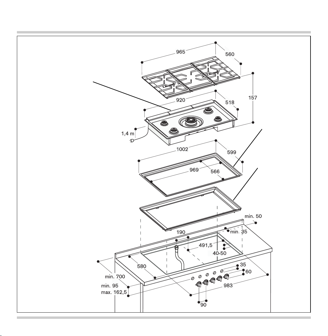
Einbaumaße
4
Dekorrahmen
Halterahmen
Gussabdeckungen Lufteinlass
Hinweis:
Der Halterahmen
und der
Dekorrahmen
(CA 429-410)
müssen separat bestellt
werden.
Zum Einsetzen in eine
Edelstahl-Arbeitsfläche wird
der Dekorrahmen
in dem
Ausschnitt verschweißt.
Zulassungsnummer für
die Schweiz: 04-028-1
Page 7
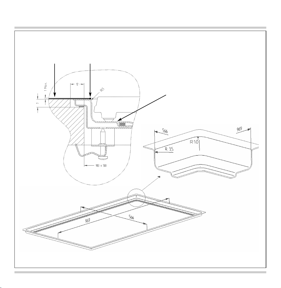
Hinweise für Einbau in Edelstahl-Arbeitsfläche
5
Einbaubeispiel
in einer
Edelstahl-Arbeitsfläche
Schweißnaht
Wichtig:
Maximale Dicke der
Edelstahl-Arbeitsplatte:
1 mm
CA 429-410
Page 8
6
Wichtige Hinweise zum Einbaumöbel
Die Kochmulde ist für den flächenbün digen Einbau
in eine Arbeitsplatte vorgesehen.
Technisch bedingt liegt die Oberkante der
Topfträger ca. 2 mm höher als die Arbeitsplatte.
Die Kochmulde ist für den Einbau in temperaturund wasserfeste Arbeitsplatten geeignet:
- Steinarbeitsplatten
- Arbeitsplatten aus Kunststoff oder Corian
- Edelstahl-Arbeitsplatten (verschweißt)
- Massivholz-Arbeitsplatten: Nur in Abstimmung mit
dem Hersteller der Arbeitsplatte (Ausschnittskanten versiegeln)
Ein Einbau in andere Arbeitsplatten
(z. B. Spanplatten) ist nicht möglich.
Die Arbeitsplatte muss mind. 70 cm tief sein.
Das Einbaumöbel muss bis 90 °C temperatur -
beständig sein.
Die Kochmulde nicht tiefer als die
Arbeitsplattenoberkante einbauen.
Alle Ausschnittarbeiten an der Arbeitsplatte sind in
einer Fachwerkstatt durch zuführen. Der Ausschnitt
muss sauber und genau ausgeführt sein, da die
Schnittkante an der Ober fläche sichtbar ist.
Die Stabilität der betroffenen Möbel muss auch
nach den Ausschnittarbeiten gewährleistet sein.
Ausschnittskanten mit einem geeigneten
Reinigungsmittel reinigen und entfetten
(Verarbeitungshinweise des Silikonherstellers
beachten).
Vorbereiten des Einbaumöbels
580
604
+1/-0
983
1007
+1/-0
R9
90∞
7
±0,5
min. 700
12
Page 9
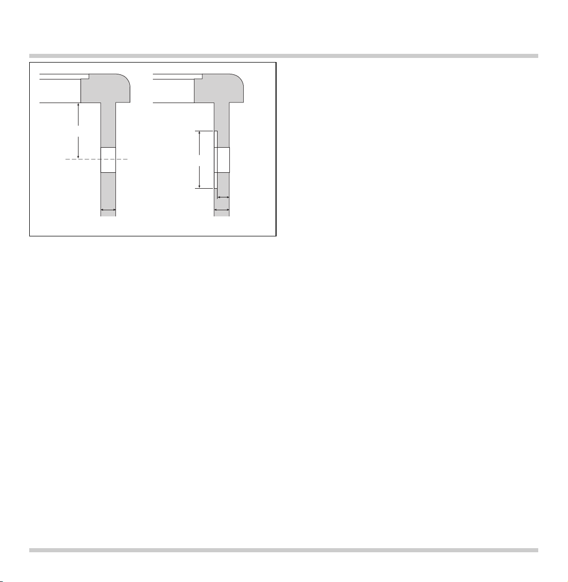
• Gemäß Abbildung die Bohrungen Ø 35 mm für die
Befestigung der Bedienknebel in der Frontseite
des Unterschrankes herstellen.
• Ist die Frontblendendicke größer als 26 mm, so
muss die Frontblende von hinten auf das Maß
80 x 470 mm soweit ausgefräst werden, dass die
Frontblendendicke an dieser Stelle nicht größer
als 26 mm ist.
7
Bohrungen in der Frontblende
min. 40
80x470
D=26
16-26
D>26
Page 10
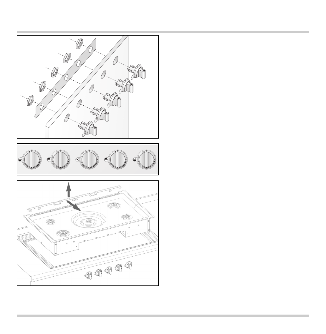
• Vor der Montage die Styropor Verpackungselemente an den Bedienknebeln entfernen und
die Schutzfolie abziehen.
• Halteblech von hinten gegen die Frontblende
halten (Winkel am Blech muss an der Rückseite
unten sein), Bedienknebel von vorne in die
Bohrungen stecken, von hinten mit den Muttern
festschrauben. Auf korrekte Zuordnung der
Kochstellen achten.
Bitte beachten: Falls das Gerät auf eine andere
Gasart umgestellt wird, den Düsenwechsel vor dem
Einbau durchführen (siehe Bedienungsanleitung).
• Halterahmen in den Ausschnitt einsetzen und
mittig ausrichten. Mit den beiliegenden
Muldenspannern fixieren.
• Dekorrahmen auf den Halterahmen legen. Auf
Planität zwischen Dekorrahmen und Arbeitsplatte
achten. Wenn nötig mit Hilfe der angebrachten
Muldenspanner justieren.
Zur Justierung bei abgenommenem Dekorrahmen
das beiliegende Kontrollblech (1 mm dick)
verwenden. Mit dem Kontrollblech den Rahmen
abfahren, das Kontrollblech muss bündig zur
Arbeitsplatte sein.
• Das beiliegende Dichtungsband entlang der
Markierungspunkte an der hinteren Seite des
Dekorrahmens festkleben.
• Dichtungsleiste an der Geräterückseite
abnehmen: 3 Schrauben lockern und die Leiste
nach vorn
und dann nach oben abziehen.
• Befestigungsmuttern der Kochmulde lösen und
Mulde vorsichtig nach oben abnehmen.
• Gehäusewanne waagrecht in den Halterahmen
einsetzen und ausrichten. Gehäusewanne an den
4 markierten Stellen mit dem Halterahmen
verschrauben.
8
Einbau der Kochmulde
Page 11
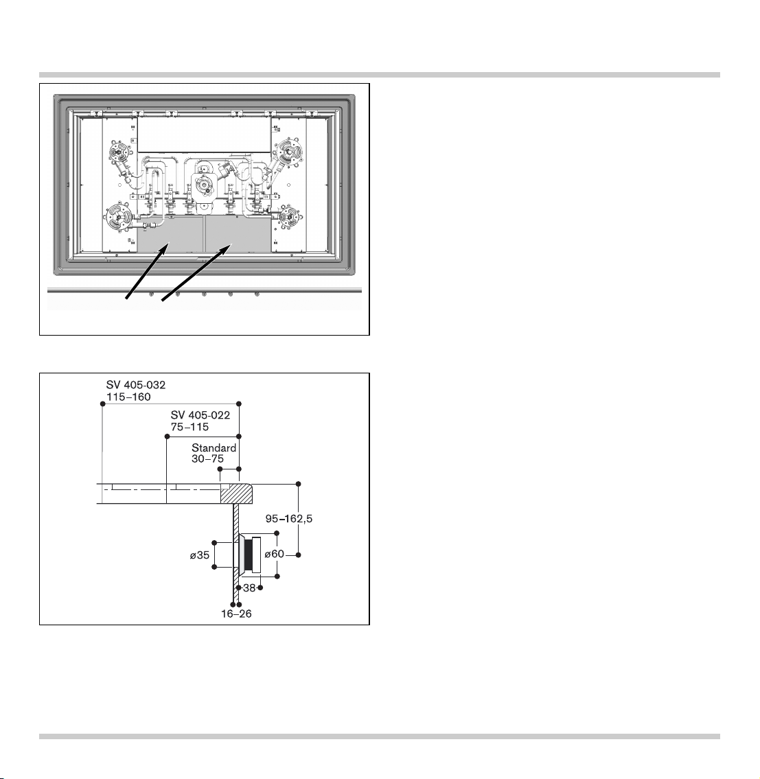
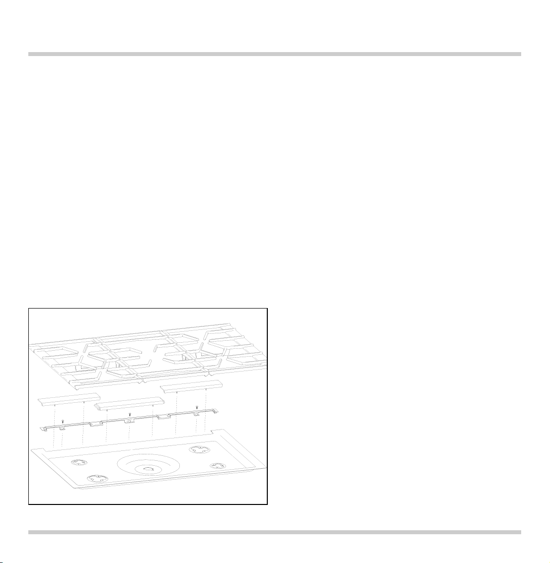
• Die beiden Abdeckbleche losschrauben, zur
Mitte schieben und abnehmen.
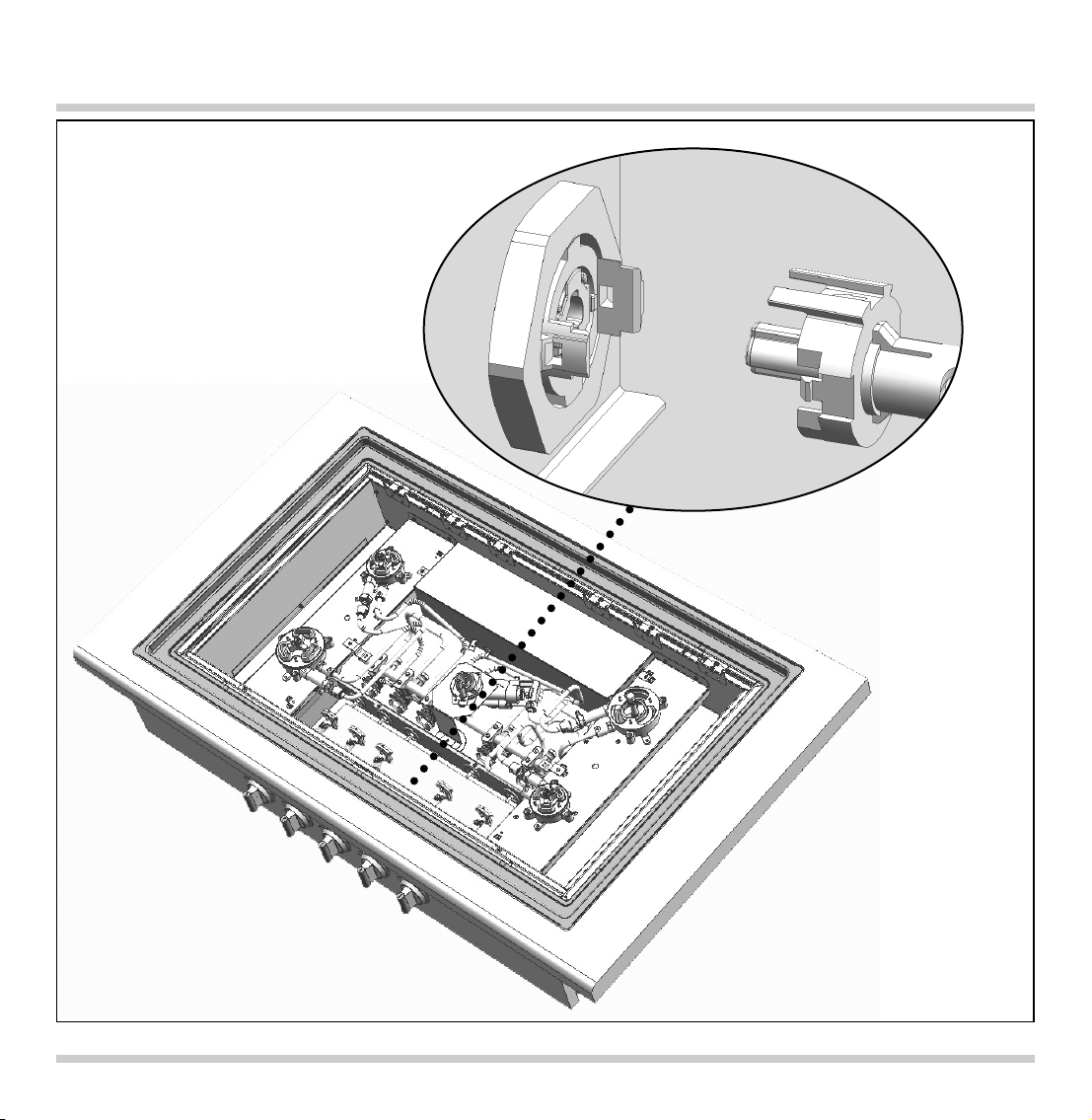
• Die Gashähne an den Brennern müssen in
Nullstellung sein (Abflachungen nach oben). Die
Achsen (Hohlprofil) auf das Vierkantprofil an den
Bedienknebeln schieben. Die Kupplung fest auf
die Zapfen an den Gashähnen aufschieben.
• Die Achsen jeweils mit der Feststellschraube
fixieren.
• Die beiden Abdeckbleche einsetzen und
festschrauben.
Für den Einbau in übertiefe Arbeitsplatten sind
Achsverlängerungen (SV 405-022 / SV 405-032) als
Zubehör erhältlich.
• Die Achsen von den Bedienknebeln gerade
abziehen (die Achsen sind fest eingerastet).
• Die längeren Achsen von hinten in die Aufnahmen
an den Bedienknebeln stecken. Darauf achten,
dass der breitere Zapfen am Bedienknebel mit
der breiteren Aufnahme an der Achse
übereinstimmt.
• Die weitere Montage ist identisch zu den
Standard-Achsen (siehe Beschreibung oben).
9
Montage der Achsen
Abdeckbleche
Page 12
10
Page 13
11
Wichtige Hinweise:
Spalt zwischen Arbeitsplatte und Kochmulde mit
einem geeigneten, temperatur beständigen
Silikonkleber (z. B. Novasil, Pactan) verfugen.
Dichtfuge mit dem vom Hersteller empfohlenen
Glättmittel glätten. Verarbeitungs hinweise des
Silikonherstellers beachten.
Ungeeigneter Silikonkleber führt bei NatursteinArbeitsplatten zu dauerhaften Verfärbungen.
Kochmulde erst nach vollständigem Austrocknen
des Silikonklebers in Betrieb nehmen (mindestens
24 Stunden, je nach Raumtemperatur).
Die Hautbildung des Silikonklebers beginnt
bereits nach wenigen Minuten. Deshalb
müssen die einzelnen Montageschritte rasch
durchgeführt werden. Üben Sie vor dem
Aufbringen des Silikonklebers die folgenden
Montageschritte und prüfen Sie die
Passgenauigkeit, um einen optimalen Einbau
zu gewährleisten.
Wichtig: Vor dem Verfugen Planität des gesamten
Gerätes überprüfen.
• Umlaufende Nut zwischen Arbeitsplatte und
Halterahmen vollständig mit Silikon füllen (auch in
die Ecken), um umlaufend ein Silikonbett zu
erhalten. Das Silikon sollte 1-3 mm über der
Arbeitsplatte überstehen.
• Dekorrahmen zentriert auf das Silikonbett
auflegen. Dekorrahmen nicht eindrücken.
• Mulde auflegen und gleichmäßig festschrauben.
• Dichtungsleiste an der Geräterückseite
aufstecken und die 3 Schrauben festziehen.
• Dekorrahmen langsam ringsum eindrücken, bis er
flächenbündig mit der Arbeitsplatte ist.
Überschüssiges Silikon bündig mit Arbeitsplatte
abziehen.
• Bei Überstand des Dekorrahmens über der
Arbeitsplatte können Sie einen Ausgleich durch
Belastung des Dekorrahmens erreichen. Dazu den
Dekorrahmen gleichmäßig während der gesamten
Trocknungszeit des Silikons belasten.
• Alle Brennerteile korrekt auflegen.
• Die drei Gussabdeckungen im hinteren Bereich
der Mulde aufstecken und einclipsen: Zuerst das
Mittelteil (längstes Teil), dann die Seitenteile.
• Topfroste auflegen. Korrekte Ausrichtung der
Topfroste beachten. Das Gaggenau Logo muss
vorn sein.
Silikon verfugen (BETRIFFT NICHT die eingeschweißte Version in Edelstahl Arbeitsplatte)
Page 14
12
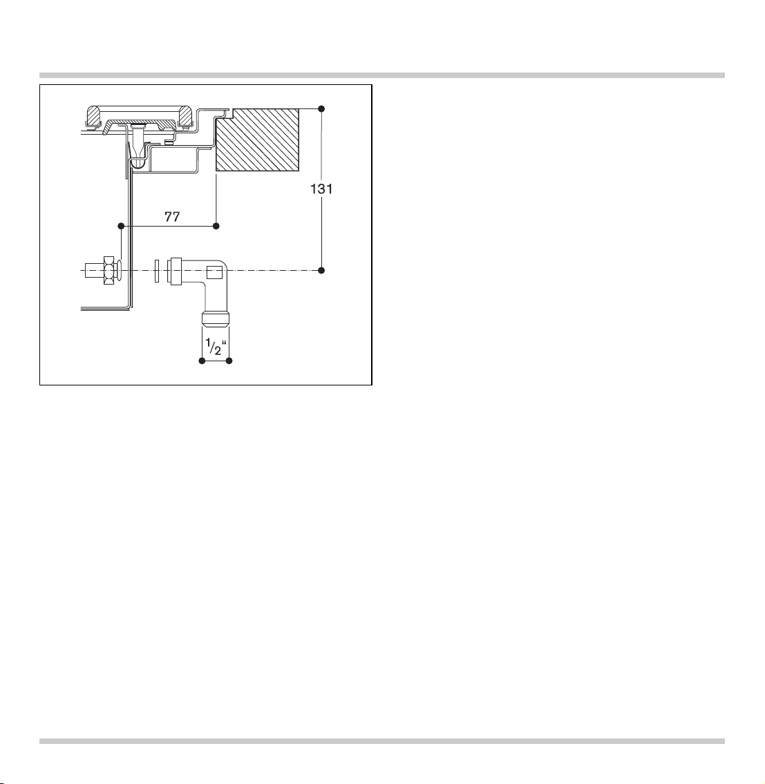
Gasanschluss
Der Gasanschluss muss so angeordnet sein, dass
der Absperrhahn zugänglich ist und gegebenen falls nach Öffnen der Möbeltür sichtbar wird.
Das Gerät ist mit einem der beiliegenden
Anschluss winkel R 1/2“ (geräteseitig) mit der
zugehörigen Dichtung an eine feste Anschluss leitung oder einem typgerechten Gas-Sicherheits schlauch nach DIN 3383 Teil 1 anzuschließen.
Besteht der Gas-Sicherheitsschlauch nur teilweise
aus Metall, so darf die Umgebungstemperatur 70 °K
nicht überschritten werden.
Bei einem Gas-Sicher heitsschlauch, der
vollkommen aus Metall besteht, ist die zulässige
Umgebungstemperatur 115°K.
Eine flexible Leitung muss so verlegt werden, dass
sie nicht mit beweglichen Teilen des Küchenelementes (z. B. Schublade) in Berührung kommen
kann.
• Die Bedienknebel auf die Nullstellung drehen.
• Das Gerät an die Gasleitung anschließen.
• Die Gasdichtheit des Anschlusses überprüfen.
• Das Gerät an das Netz anschließen und auf
Funktion überprüfen. Falls das Gerät abschaltet
kann sich Luft in der Gasleitung befinden.
Bedienknebel auf 0 drehen und Brenner erneut
zünden. Diesen Vorgang ggf. wiederholen, bis das
Gerät zündet.
Page 15

Please observe the general safety notes and the
important information.
The installing technician is responsible for perfect
functioning of the appliance at its installa tion
location.
He must show the user how to switch off the
electricity and gas supply whenever required.
After unpacking, check the appliance for any
transportation damage and report this immediately
to the transportation company.
Caution:
before connecting the appliance, please check
whether the local connection conditions such as
gas type, gas pressure and mains voltage match the
appliance settings. This gas hob conforms to the
categories that are specified on the rating plate.
The rating plate can be found on the appliance and
additionally on the quality control slip which is
included with these instructions. By replacing
nozzles, it is possible to set the appliance to any
gas listed on the rating plate.
If the data should not match, the appliance must
be changed over to the required gas type and the
available pressure.
As this gas hob is not intended for connection to an
exhaust gas system, pay attention to the applicable
installation conditions.
The appliance may be installed in kitchen
combinations made of wood or similar combustible
materials without taking additional measures. The
rear wall must consist of non-combustible material.
A minimum distance of 300 mm from heat-sensitive
items of furnishing or contact surfaces (cupboard
side panel) must be observed.
The hob conforms to appliance class 3 and must be
installed in the worktop as shown in the installation
sketch.
Do not install the appliance under a suspended
cupboard. For installation under a vapour extractor,
a minimum clearance of 760 mm must be
observed. Wall trims must be heat-resistant, and the
minimum distance between the hob and the wall
trim is at least 35 mm.
The appliance must be installed and connected by
an authorised gas installer. The installation must
conform with all current regulations of the gas
supply companies and the regional construction
regulations.
Technical modifications reserved.
13
Important Notes
Page 16

This household gas cooker has a total rated thermal
load of 17 kW (Hs).
Simultaneous use of all cooking positions of the
cooker generates heat and humidity in the room
where it is installed. This is why atten tion must be
paid to good kitchen ventilation.
This can be guaranteed for example by installing
an extractor hood with a minimum air output of
264 m
3
/h (= 15 m3/h per kW thermal load).
To ensure ventilation, the room in which this
appliance is installed must have a suitable opening,
like an exterior door or a window that can be
opened.
When using the household gas cooker, the extractor
hood must be operated in such a way, that, the
more cooking positions are used, the higher the air
output level must be.
Electrical connection (AC 220-240 V) is established
by means of a connecting cable with an earthing
contact plug connected to an earthed socket, which
must also be accessible after installation of the gas
hob.
If, after installation of the gas hob, not all poles can
be isolated from the mains by removing the plug,
an isolating device with a contact gap of at least
3 mm must be permanently installed. When estab lishing connections, make sure that the connecting
lead cannot come into contact with hot parts of the
gas hob or other hot parts.
Turn all control knobs to the OFF position before
connecting the appliance to the power supply.
The mains connecting cable must at least
correspond to type H 05 V2V2 3G 0.75 or it must be
correspondingly heat-resistant (at least 90 °C).
The mains connecting cable must only be
purchased through and connected by an
authorised specialist.
Pay attention to the information on the rating plate
and connect the PE conductor. Connect the
connecting cable to the mains.
14
Note on Ventilation Electrical Connection
Page 17

15
Measurements
decorative frame
supporting frame
cast iron covers for air intake
Note:
the supporting frame
and the decorative frame
(CA 429-410) must be
ordered separately.
If installed in a stainless
steel worktop, the
decorative frame
is
welded into the cut-out.
Page 18

16
Notes for Installation in a Stainless Steel Worktop
Example of an installation
in a stainless steel
worktop
welded seam
Important:
maximum thickness of
the stainless steel
worktop: 1 mm
CA 429-410
Page 19

Important notes concerning the cabinet
The gas cooker is suitable for flush mounting into a
worktop. For technical reasons, the top of the pot
grids will be approx. 2 mm above the worktop
surface.
The gas hob can be fitted into the following types of
heat and water-resistant work surfaces:
- Stone work surfaces
- Work surfaces made of plastic or Corian
- Stainless steel work surfaces (welded)
- Solid wood work surfaces, following consultation
with the manufacturer of the work surface (sealing
edges of cut-out)
Installation in other types of work surface
(e.g. chipboard) is not possible.
Worktop depth min. 70 cm.
The unit into which the hob is built must be heat
resistant up to 90 °C.
Do not install the cooktop lower than the work
surface.
All cut-outs in the worktop are to be carried out at a
specialist workshop. The cut must be clean and
precise, since the cut edge is visible on the
surface.
The stability of the furniture being worked on must
also be ensured following the cut-outs.
Clean and degrease the edge of the cut-out, using
a suitable cleaner (follow the instructions given by
the silicone manufacturer).
17
Preparing the Cabinet
580
604
+1/-0
983
1007
+1/-0
R9
90∞
7
±0,5
min. 700
12
Page 20

• As shown in the installation sketch, drill the
Ø 35 mm holes to secure the control knobs in the
cabinet front.
• If the cabinet front is thicker than 26 mm, the front
must be routed from the back to max. 26 mm on
an area of 80 x 470 mm.
18
Drilling the Holes in the Cabinet Front
min. 40
16-26
80x470
D=26
D>26
Page 21

• Before installation, remove all styrofoam
packaging from the control knobs and peel off
the protective film.
• Hold the support plate from the rear against the
cabinet front (make sure the angled edge of the
support plate is on the bottom), insert control
knobs into the holes, secure from the rear with the
nuts. Take care to install control knobs in the
correct order.
Please note: if you want to convert the appliance
to a different type of gas, change the nozzles
before installing the appliance (see user manual).
• Insert the supporting frame into the cut-out and
align it centrally. Secure the appliance with the
clamping screws included.
• Place the decorative frame onto the supporting
frame. Be careful to align the decorative frame
level with the worktop. If necessary, adjust the
clamping screws.
For alignment you can take off the decorative
frame and use the metal adjusting piece included
(thickness 1 mm). Slide the adjusting piece along
the frame and make sure the adjusting piece is
level with the worktop.
• Stick the sealing tape along the marker points
onto the rear part of the decorative frame.
• Detach the sealing strip at the back of the
appliance: loosen 3 screws and take off the
sealing strip forward
and then up .
• Undo trough securing nuts and carefully detach
the trough.
• Horizontally insert the trough into the supporting
frame and align. Screw the trough onto the
supporting frame at the 4 marked points.
19
Installing the Cooker
Page 22

• Loosen both cover plates, slide to the center and
remove.
• The gas taps of the burners must be in the off
position (flat side to the top). Slide the spindles
(hollow section) on the square profile on the back
of the control knobs. Firmly slide the coupling
onto the stud on the taps.
• Fix the spindles with the screws provided.
• Replace and screw on both cover plates.
Spindle extensions (SV 405-022 / SV 405-032) are
available should the appliance be installed in a
worktop which is non-standard depth.
• Pull the spindles horizontally from the control
knobs (the spindles are tightly fitted).
• Insert the longer spindles from behind into the
fittings of the control knobs. Be careful that the
broader pin of the control knob fits the broader
fitting of the spindle.
• Continue the installation as described above for
the standard spindles.
20
Installing the Spindles
cover plates
Page 23

21
Page 24

Important notes:
seal the space between the work surface and the
hob with a suitable temperature resistant silicone
(e.g. Novasil, Pactan) and smooth the joint with the
suitable wetting agent recommended by the
manufacturer. Follow the manufacturer’s
instructions.
Use of unsuitable silicone on natural stone worktops
can cause permanent discoloration.
Wait until the silicone has hardened completely (at
least 24 hours depending on the room temperature)
until switching on the cooker.
Silicone starts to cure after a few minutes.
Therefore the installation has to be done
swiftly. It is advisable you test the following
installation steps and check the proper
alignment before applying the silicone to
guarantee a perfect installation.
Important: before sealing with silicone, check the
whole appliance is aligned level with the worktop.
• Completely fill the gap between worktop and
supporting frame with silicone (also the corners).
There should be a bead of silicone all around. The
silicone should protrude 1-3 mm above the
worktop.
• Place the decorative frame onto the silicone bead.
Do not press down the decorative frame.
• Place the trough into the supporting frame and
screw on evenly.
• Replace the sealing strip at the back of the
appliance and tighten the 3 screws.
• Gently and evenly push the decorative frame all
around into the silicone bead until it is flush with
the worktop. Remove excess silicone flush with
the worktop.
• Should the decorative frame protrude above the
worktop apply pressure to adjust. Place an even
weight on the decorative frame while the silicone
hardens.
• Replace all burner parts correctly.
• Replace the three cast iron covers on the rear of
the cooker and push down until they engage: first
the (longer) middle part, then the parts on the
sides.
• Replace the pod grids. The Gaggenau logo must
be facing to the front.
22
Silicone Sealing (APPLIES NOT TO the version welded into a stainless-steel worktop)
Page 25

The gas connection must be in a location that
permits access to the shut-off valve and which,
if applicable, is visible after opening the door of
the cabinet.
By means of the included R 1/2“ connection bracket
(on the appliance end) with the affiliated washer,
the appliance must be connected to a fixed
con nec ting line or a gas safety hose to DIN 3383
Part 1 that corresponds to the type concerned.
An ambient temperature of 70 °K must not be
exceeded if the gas safety hose consists only partly
of metal. The permissible ambient temperature for
a gas safety hose that consists completely of metal
is 115 °K.
If a flexible line is used, it must be laid in such a
way that it cannot come into contact with moving
parts of the kitchen element (e.g. drawer).
• Turn all control knobs to the off position.
• Connect the appliance to the gas supply.
• Check the installation for gas leaks.
• Connect the appliance to the power supply, and
check for correct functioning. If the appliance
switches off there may be air in the gas supply
line. Turn the control knobs to the off position and
relight. This may need to be repeated until the
appliance ignites.
23
Gas Connection
Page 26

Veuillez tenir compte des consignes de sécurité et
instructions importantes.
L ’installateur est responsable du bon
fonctionnement de l’appareil sur son lieu
d’utilisation. Il doit expliquer à l’utilisateur le
fonctionnement de l’appareil à l’aide de la notice
d’utilisation et lui indiquer comment il peut en cas
de besoin couper l’alimentation en électricité et en
gaz.
Après déballage, vérifiez que l’appareil n’est pas
endommagé et signalez si nécessaire tout de suite
au transporteur les dommages éventuellement
constatés.
Attention :
Avant de brancher l’appareil, veuillez vérifier si les
conditions locales (type et pression du gaz, tension
électrique du secteur) correspondent aux réglages
de l’appareil. Vous trouverez les informations
nécessaires sur la plaque signalétique ou sur
l’autocollant du branchement du gaz. Cette table
de cuisson à gaz correspond aux catégories
figurant sur la plaque signalétique. La plaque
signalétique se trouve sur l’appareil ainsi que sur la
fiche additionnelle jointe. L ’adaptation aux gaz
figurant sur la plaque signalétique se fait par
changement des injecteurs. Si les données ne
correspondent pas, il faut adapter l’appareil au
type et à la pression du gaz. Cette table de cuisson
à gaz n’étant pas prévue pour être branchée à un
conduit de fumée, veuillez tenir compte des
conditions d’installation en vigueur.
Il est possible de poser cet appareil dans des
ensembles de cuisine en bois ou autre matériau
inflammable sans prendre des précautions
complémentaires. La cloison située derrière
l’appareil ne doit pas être constituée d’un matériau
inflammable.
Il faut respecter une distance minimale de 300 mm
avec les meubles ou surfaces sensibles à la chaleur
(côtés d’éléments).
La table de cuisson appartient à la classe 3 et doit
donc être encastrée dans le plan de travail
conformément au schéma de montage.
Il est interdit de l’installer sous un élément haut. Si
elle doit être posée sous une hotte aspirante, il faut
respecter une distance minimale de 760 mm. Les
joints de cloison doivent être résistants à la chaleur,
la distance minimale entre la table et le joint de
mur est de 35 mm.
La table de cuisson à gaz doit être installée et
raccordée par un poseur agréé par le fournisseur
de gaz, dans le respect de toutes les règles en
vigueur.
En Suisse
, les dispositions suivantes doivent être
prises en considération lors du montage et de
l’installation de l’appareil :
– directives Gaz de la SSIGE G1 (2002)
– directive CFST n° 1942 : Gaz liquéfié, partie 2
– prescriptions de l’association des Établissements
cantonaux d’Assurance Incendie (AEAI)
ainsi que les conditions d’installation du fabricant.
Sous réserve de modifications techniques.
24
Remarques importantes
Page 27

Cet appareil de cuisson ménager à gaz a une
puissance nominale de 17 kW (Hs).
L ’utilisation simultanée de tous les foyers de
l’appareil entraîne un fort dégagement de chaleur
et d’humidité dans la pièce, de sorte qu’il faut
prendre des mesures appropriées d’aération et de
ventilation.
On pourra par exemple prévoir d’installer une hotte
aspirante à évacuation, dont la capacité minimale
d’extraction est de 264 m
3
/h (= 15 m3/h par kW de
puissance nominale).
Pour l’aération, il faut prévoir des possibilités
d’entrée d’air (porte donnant sur l’extérieur, fenêtre
ouvrante, ...).
Lorsque l’appareil de cuisson à gaz est en marche,
il faut adapter la puissance d’extraction de la hotte
aspirante en fonction du nombre de brûleurs en
fonction.
Le branchement électrique (CA 220-240 V) se fait
au moyen d’un cordon muni d’une fiche de terre
(2P + T) et d’une prise de courant avec terre qui
doit rester accessible même après l’installation de
la table de cuisson.
Si après la pose de la table de cuisson, l’appareil
ne peut pas être isolé du secteur sur tous les pôles
par débranchement du connecteur, il faut prévoir
dans l’installation électrique un dispositif de
sectionnement dont les contacts sont espacés d’au
moins 3 mm. En procédant au branchement, veiller
à ce que le cordon d’alimentation ne puisse pas
entrer en contact avec des parties chaudes de la
table ou d’autres éléments.
Mettez tous les boutons en position 0 avant de
brancher l’appareil au secteur.
Le cordon d’alimentation électrique doit être au
minimum du type H 05 V2V2 3G 0,75 ou bien être
résistant à la température (au moins 90 °C).
Le cordon d’alimentation électrique doit être
fourni et raccordé seulement par un technicien
qualifié.
Respecter les indications de la plaque signalétique,
brancher le conducteur de protection. Brancher le
cordon d’alimentation au secteur.
25
Aération Raccordement électrique
Page 28

26
Cotes d’encastrement
cadre décor
cadre support
couvercles en fonte, entrée d’air
Remarque :
Il faut commander
séparément le cadre
support
et le cadre
décor
(CA 429-410).
Pour installer la table de
cuisson dans un plan de
travail en inox, il faut souder
le cadre décor
dans la
découpe.
Numéro d’agrément pour
la Suisse : 04-028-1
Page 29

27
Instructions en cas de pose dans un plan de travail en inox
Exemple de pose dans un
plan de travail en inox
soudure
Important :
épaisseur maximale du
plan de travail en inox :
1 mm
CA 429-410
Page 30

Recommandations importantes concernant le
meuble
La table de cuisson est conçue pour être encastrée
à fleure de plan de travail. Pour des raisons
techniques, le bord supérieur des grilles se situe à
2 mm au-dessus du plan de travail.
La table de cuisson est conçue pour être intégrée
dans un plan de travail résistant à la chaleur et à
l’eau :
- plan de travail en pierre
- plan de travail en matière plastique ou en Corian
- plan de travail en inox (soudé)
- plan de travail en bois massif : seulement après
concertation avec le fabricant du plan de travail
(appliquer un produit de scellage sur les chants
de coupe)
La pose dans d’autres types de plan de travail
(aggloméré par exemple) n’est pas possible.
Le plan de travail doit avoir une profondeur
minimale de 70 cm.
Le meuble où est encastrée la table de cuisson doit
pouvoir résister à une température de 90°C.
Ne pas installer la table de cuisson plus bas que la
surface du plan de travail.
Faire réaliser les découpes dans le plan de travail
par un atelier spécialisé. La découpe doit être
nette et précise, car le bord de coupe est visible
en surface.
La stabilité des meubles doit être garantie après
les opérations de découpe.
Nettoyer et dégraisser les bords de coupe avec un
produit de nettoyage adéquat (respecter les
instructions d’application du fabricant du silicone).
28
Préparation du meuble
580
604
+1/-0
983
1007
+1/-0
R9
90∞
7
±0,5
min. 700
12
Page 31

• Conformément à la figure, percer les trous de
Ø 35 mm pour la fixation des boutons dans la
façade de l’élément bas.
• Si le bandeau avant a une épaisseur supérieure à
26 mm, il faut réaliser des fraisages par l’arrière à
la cote de 80 x 470 mm de façon qu’à cet endroit,
son épaisseur ne soit pas supérieure à 26 mm.
29
Perçages du bandeau avant
min. 40
80x470
D=26
16-26
D>26
Page 32

• Avant la pose, éliminer les éléments d’emballage
en polystyrène se trouvant sur les boutons de
commande et retirer le film de protection.
• Tenir la plaque de maintien par l’arrière contre le
bandeau avant (l’équerre de la plaque doit être
en bas de la face arrière), enfoncer les boutons
par l’avant dans les trous, et les fixer par l’arrière
avec les écrous. S’assurer que les boutons
correspondent bien aux brûleurs.
Remarque : en cas de changement de type de
gaz, il faut changer les injecteurs avant l’installation
(voir la notice d’utilisation).
• Insérer le cadre support dans la découpe et le
centrer. Fixer le cadre au moyen des crochets
fournis.
• Placer le cadre décor sur le cadre support.
Vérifier que le cadre décor repose bien à plat sur
le plan de travail. Si nécessaire, ajuster au moyen
des tendeurs de table.
Pour procéder à l’ajustement lorsque le cadre
décor est enlevé, utiliser la plaque de contrôle
fournie (épaisseur 1 mm). Parcourir le cadre avec
la plaque de contrôle qui doit affleurer au plan de
travail.
• Coller le profilé d’étanchéité fourni le long des
marquages (points), à l’arrière du cadre décor.
• Enlever la baguette d’étanchéité située à l’arrière
de l’appareil: Desserrer 3 vis et tirer la baguette
vers l’avant
puis vers le haut .
• Desserrer les écrous de fixation du dessus inox et
le retirer vers le haut avec précaution.
• Insérer le caisson horizontalement dans le cadre
support et ajuster. Visser le caisson de l’appareil
au cadre support aux 4 points indiqués.
30
Pose de la table de cuisson
Page 33

• Dévisser les deux plaques de recouvrement, les
pousser vers le milieu et les enlever.
• Les robinets à gaz des brûleurs doivent être en
position zéro (méplats tournés vers le haut).
Pousser les axes (profilé creux) sur le profilé
carré des boutons. Engager à fond le cardan sur
les méplats des robinets à gaz.
• Bloquer chaque axe avec la vis de blocage.
• Poser les deux plaques de recouvrement et les
visser.
Pour installer la table dans un plan de travail plus
profond, utiliser des prolongateurs d’axe (SV 405022 / SV 405-032) disponibles en accessoires.
• Enlever les axes des boutons en tirant dans l’axe
(les axes sont encliquetés).
• Emboîter les axes les plus longs par l’arrière dans
les logements des boutons. Veiller à ce que le
tenon large du bouton corresponde au logement
large de l’axe.
• La suite du montage est identique aux axes
standard.
31
Montage des axes
Plaques de recouvrement
Page 34

32
Page 35

Remarques importantes :
La fente entre le plan de travail et la table de
cuisson est comblée au moyen d’une colle silicone
résistant à la température (type Novasil, Pactan,
etc.). Lisser le joint d’étanchéité avec l’agent de
lissage préconisé par le fabricant. Respecter les
instructions d’application du fabricant du silicone.
L ’emploi d’une colle silicone non adaptée
provoque des décolorations durables sur les plans
de travail en pierre naturelle.
Attendre le séchage complet de la colle silicone
pour mettre la table de cuisson en service (au
moins 24 heures, selon la température ambiante).
Une pellicule commence à se former au bout
de quelques minutes sur la colle silicone. Il
faut donc effectuer les opérations de montage
rapidement et sans s’arrêter. Avant d’appliquer
la colle silicone, s’exercer au montage "à sec"
et vérifier la précision d’ajustage afin de
garantir une pose optimale.
Important : Avant de faire les joints, vérifier que
l’ensemble de l’appareil est bien d’aplomb.
• Garnir entièrement de silicone la gorge
périphérique entre le plan de travail et le cadre
support (y compris dans les angles) afin d’obtenir
une semelle de silicone sur tout le tour. Le
silicone doit dépasser du plan de travail sur 1 à 3
mm.
• Poser le cadre décor bien centré sur la semelle
en silicone. Ne pas appuyer sur le cadre décor.
• Poser le dessus inox et le visser de manière
régulière.
• Emboîter la baguette d’étanchéité à l’arrière de
l’appareil et serrer les 3 vis.
• Appuyer lentement sur tout le tour du cadre décor
jusqu’à ce qu’il affleure le plan de travail. Éliminer
le silicone en excès de façon à obtenir un joint
régulier.
• Si le cadre décor dépasse du plan de travail, vous
pouvez rattraper la différence en exerçant une
charge sur le cadre décor. Pour ce faire, charger
le cadre de manière régulière pendant tout le
temps de séchage du silicone.
• Poser correctement tous les éléments des
brûleurs.
• Emboîter et clipser les trois caches en fonte dans
la partie arrière de la table : commencer par la
partie du milieu (élément le plus long), puis poser
les éléments latéraux.
• Poser les grilles porte-casseroles. Vérifier
qu’elles sont bien alignées. Le logo Gaggenau
doit être à l’avant.
33
Faire les joints en silicone (NE CONCERNE PAS la version soudée dans un plan de travail en inox)
Page 36

Le branchement du gaz doit être effectué de façon
que le robinet d’arrêt soit accessible et, le cas
échéant, visible après ouverture de la porte du
meuble.
L ’appareil doit être raccordé à un tuyau d’arrivée
fixe ou à un flexible de sécurité conforme à DIN
3383 partie 1, au moyen d’un des raccords
angulaires R 1/2“ fournis (côté appareil), avec le
joint adéquat.
Si le flexible de sécurité n’est composé que
partiellement de métal, la température ambiante ne
doit pas dépasser 70 °K.
Si le flexible de sécurité est entièrement en métal,
la température ambiante autorisée est de 115 °K.
Le flexible doit être posé de façon à ne pas être en
contact avec des parties mobiles de l’élément de
cuisine (tiroir par exemple).
• Mettre les boutons en position zéro.
• Brancher l’appareil au tuyau de gaz.
• Vérifier l’étanchéité du branchement.
• Raccorder l’appareil au secteur électrique et
effectuer un essai de fonctionnement. Si l’appareil
se coupe, il y a peut-être de l’air dans le tuyau de
gaz. Remettre le bouton à 0 et réallumer le
brûleur. Recommencer l’opération si nécessaire
jusqu’à ce que l’appareil s’allume.
34
Branchement du gaz
Page 37

Osservare le indicazioni di sicurezza e le
indicazioni importanti.
L ’installatore è responsabile del corretto
funzionamento dell’apparecchio nel luogo di
installazione.
Egli deve spiegare all’utilizzatore il funzionamento
in base al manuale d’uso ed indicargli come
spegnere l’alimentazione di corrente e gas in caso
di necessità.
Dopo aver disimballato l’apparecchio verificare
l’eventuale presenza di danni da trasporto che
andranno comunicati immediatamente all’impresa
dei trasporti.
Attenzione:
Prima di collegare l’apparecchio verificare se le
condizioni in loco, quali il tipo di gas, la pressione
del gas e la tensione di rete corrispondono alle
impostazioni dell’apparecchio. Le informazioni
necessarie sono riportate sull’adesivo sul raccordo
per il gas oppure sulla targhetta dell’apparecchio.
Questo piano di cottura a gas corrisponde alle
categorie riportate sulla targhetta. La targhetta si
trova sull’apparecchio ed inoltre anche sul foglio
complementare allegato. Il cambio degli ugelli
permette di regolare ogni tipo di gas ivi indicato.
Se i dati non corrispondono l’apparecchio deve
essere adattato al tipo di gas e alla pressione
presenti. Poiché questo piano di cottura non è
previsto per l’allacciamento ad un impianto di
convogliamento dei gas di scarico, vanno osservate
le relative condizioni di installazione.
L ’apparecchio può essere installato in cucine
componibili di legno o simile materiale
combustibile senza dovere adottare misure
complementari. La parete dietro l’apparecchio
deve essere in materiale ignifugo.
La distanza minima tra l’apparecchio e le parti dei
mobili sensibili al calore o le superfici di appoggio
(parete laterale del mobile) deve essere di
300 mm.
Il piano di cottura corrisponde alla classe di
apparecchi 3 e deve essere installato nel piano di
lavoro come indicato sul disegno.
Non è consentita l’installazione sotto un pensile. Nel
caso di un’installazione sotto una cappa ad
aspirazione, va rispettata una distanza minima di
760 mm. Le alzatine devono essere resistenti al
calore e la distanza minima tra il piano di cottura e
l’alzatina è di 35 mm.
L’installazione e l’allacciamento del piano di cottura
a gas devono essere eseguiti solo da un installatore
autorizzato dall’impresa erogatrice di gas in
rispetto di tutte le norme valide.
In Svizzera
devono essere osservate le seguenti
norme in fase di montaggio ed installazione:
– direttive gas della SSIGA G1 (2002)
– guida CFSL N. 1942: Gas liquefatti, parte 2
– direttive dell’Associazione degli Istituti Cantonali
di Assicurazione Antincendio (AICAA)
nonché le condizioni di installazione del produttore.
Con la riserva di modifiche tecniche!
35
Indicazioni importanti
Page 38

Questo apparecchio a gas per uso domestico ha un
carico nominale di calore di 17 kW (Hs).
Poiché quando si utilizzano contemporaneamente
tutti i fuochi si produce maggiore calore ed umidità
nell’ambiente in cui l’apparecchio è installato, è
necessario provvedere ad adeguate misure di
aerazione e ventilazione.
Per es. è possibile installare una cappa ad
aspirazione con un volume di portata di almeno
264 m
3
/h (= 15 m3/h per kW di carico nominale).
Per la ventilazione devono essere presenti apposite
aperture, per es. una porta verso l’esterno o una
finestra che può essere aperta.
Durante il funzionamento del piano di cottura a gas
per uso domestico la cappa deve funzionare di
modo che maggiore è il numero di fuochi accesi,
maggiore è anche il volume di portata da
selezionare.
L ’allacciamento elettrico (AC 220-240 V) avviene
con un cavo dotato di spina di protezione tramite
una presa con messa a terra che deve essere
raggiungibile anche dopo l’installazione del piano
di cottura a gas.
Se dopo l’installazione il piano di cottura a gas non
può essere staccato dalla rete con tutti i poli tirando
la spina dalla presa, è necessario prevedere, in
fase di installazione, un dispositivo di separazione
con una distanza minima tra i contatti di 3 mm. Nel
realizzare gli allacciamenti badare che il cavo non
venga a contatto con le parti calde del piano di
cottura o con altri componenti caldi.
Posizionate tutte le manopole di comando su 0,
prima di collegare l’apparecchio alla corrente.
Il cavo di allacciamento alla rete deve essere
almeno corrispondente al tipo H 05 V2V2 3G 0,75
o adeguatamente resistente alla temperatura
(min. 90 °C).
Il cavo di allacciamento alla corrente deve
essere acquistato e collegato solo ed
esclusivamente da un elettricista autorizzato.
Osservare quanto riportato sulla targhetta,
collegare il conduttore di protezione. Collegare il
cavo di allacciamento alla rete.
36
Indicazione per la ventilazione Allacciamento elettrico
Page 39

37
Misure di incasso
Telaio decorativo
Telaio di supporto
Coperture in ghisa per
ingresso aria
Nota:
Il telaio di supporto
e quello
decorativo
(CA 429-410)
devono essere ordinati
separatamente.
Per il montaggio in un piano di
lavoro di acciaio inox, il telaio
decorativo
viene saldato
nell’intaglio.
Codice di omologazione
per la Svizzera: 04-028-1
Page 40

38
Note per il montaggio in piani di lavoro di acciaio inox
Esempio di montaggio in
un piano di lavoro di
acciaio inox
Giunto saldato
Importante:
spessore massimo del
piano di lavoro di
acciaio inox: 1 mm
CA 429-410
Page 41

Indicazioni importanti sui mobili da incasso
Il piano cottura è destinato al montaggio a filo in un
piano di lavoro. Per motivi tecnici il bordo superiore
della griglia per pentole sporge di ca. 2 mm dal
piano di lavoro.
Il piano di cottura è adatto per l'installazione in
piani di lavoro resistenti alla temperatura e
all'acqua:
- piani di lavoro in pietra
- piani di lavoro in pvc o corian
- piani di lavoro in acciaio inox (saldati)
- piani di lavoro in legno massiccio: solo in accordo
con il produttore del piano (sigillare i bordi
dell'intaglio)
Non è possibile l'installazione in piani di lavoro
diversi (per es. i piani in truciolato).
Il piano di lavoro deve essere profondo almeno 70 cm.
Il mobile da incasso deve essere resistente a
temperature di almeno 90 °C.
Non montare il piano di cottura ad una profondità
maggiore del bordo superiore del piano di lavoro.
Tutti gli intagli nel piano di lavoro devono essere
eseguiti da un’officina specializzata. L ’intaglio deve
essere pulito ed esatto poiché i punti di taglio sono
visibili sulla superficie.
La stabilità del mobile in questione deve essere
garantita anche dopo l’intaglio.
I bordi dell’intaglio vanno puliti e sgrassati con un
detergente adeguato (osservare le indicazioni di
lavoro del produttore di silicone).
39
Preparare il mobile da incasso
580
604
+1/-0
983
1007
+1/-0
R9
90∞
7
±0,5
min. 700
12
Page 42

• Realizzate i fori da Ø 35 mm secondo lo schizzo,
per fissare le manopole di comando nella parte
frontale del mobile.
• Se lo spessore del pannello frontale è maggiore
di 26 mm, esso deve essere lavorato dal lato
posteriore con un fresa su 80 x 470 mm, affinché il
suo spessore in questo punto non sia superiore a
26 mm.
40
Fori nel pannello frontale
min. 40
80x470
16-26
D=26
D>26
Page 43

• Prima di procedere al montaggio, rimuovere gli
imballaggi di polistirolo dalle manopole di
comando e tirare la pellicola protettiva.
• Mantenete il supporto in lamiera dal retro contro il
pannello frontale (l’angolare della lamiera deve
trovarsi in basso sul retro), inserite le manopole
davanti nei fori e fissatele con i dadi dal lato
posteriore. Accertarsi di assegnarle
correttamente alle piastre di cottura.
Osservare: Se l’apparecchio deve essere adattato
ad un altro tipo di gas, sostituire gli ugelli prima del
montaggio (v. Istruzioni per il comando).
• Inserire il telaio di supporto nell’intaglio e
centrarlo. Fissare con gli elementi forniti in
dotazione.
• Poggiare il telaio decorativo sul telaio di supporto.
Accertarsi che il telaio decorativo e il piano di
lavoro combacino tra di loro. Qualora necessario
regolare con gli elementi di fissaggio montati.
Per regolare il telaio decorativo utilizzare la
lamiera di controllo fornita in dotazione (spessa 1
mm). Percorrere il telaio con la lamiera di
controllo che deve essere a filo con il piano di
lavoro.
• Incollare il nastro di tenuta in dotazione lungo i
punti contrassegnati sul lato posteriore del telaio
decorativo.
• Rimuovere il listello di tenuta sul retro
dell’apparecchio. Allentare 3 viti e sfilare il listello
in avanti
e in alto .
• Svitare i dadi di fissaggio dal piano cottura e
rimuoverlo con cautela verso l’alto.
• Inserire la vasca d’alloggiamento orizzontalmente
nel telaio di supporto ed allinearla. Avvitare la
vasca sul telaio di supporto nei 4 punti
contrassegnati.
41
Montaggio del piano di cottura
Page 44

• Svitate le due lamiere di copertura, spingetele
verso il centro e rimuovetele.
• I rubinetti del gas sui bruciatori devono essere
posizionati su zero (lato piatto in alto). Spingere
gli assi (profilo cavo) sul profilo quadro delle
manopole. Infilare i giunti sui perni dei rubinetti
del gas.
• Fissate gli assi rispettivamente con la vite di
fissaggio.
• Montate e fissate le due lamiere di copertura.
Per il montaggio in piani di lavoro più profondi del
normale sono disponibili come accessori le
prolunghe per gli assi (SV 405-022 / SV 405-032).
• Sfilare gli assi dalle manopole (gli assi sono
incastrati).
• Inserite gli assi più lunghi dal lato posteriore negli
alloggiamenti sulle manopole di comando.
Accertatevi che il perno più largo sulla manopola
corrisponda con l’alloggiamento più largo
dell’asse.
• L ’ulteriore montaggio è identico come per gli assi
standard.
42
Montaggio degli assi
Lamiere di copertura
Page 45

43
Page 46

Indicazioni importanti:
Applicare della colla siliconica idonea e resistente
alle alte temperature (ad es. Novasil, Pactan) nella
fessura tra il piano di lavoro ed il piano di cottura.
Lisciare la fuga con un prodotto consigliato dal
fornitore. Osservare le indicazioni per
l’applicazione fornite dal produttore del silicone.
Una colla siliconica non idonea comporta
decolorazioni indelebili sui piani di lavoro in pietra
naturale.
Mettere in funzione il piano di cottura solo dopo
che il silicone si è asciugato completamente
(almeno 24 ore secondo la temperatura ambiente).
Il silicone comincia a formare una pellicola
già dopo pochi minuti. Per questo le singole
fasi di montaggio devono essere eseguite
rapidamente. Provate, prima di applicare il
silicone, le seguenti fasi di montaggio e
verificate l’esattezza di adattamento per
garantire un’installazione ottimale.
Importante: Prima di sigillare controllate che
l’intero apparecchio sia piano.
• Riempire completamente con il silicone (anche gli
angoli) la scanalatura tra piano di lavoro e telaio di
supporto per ottenere un letto di silicone
tutt’intorno. Il silicone deve sporgere di 1-3 mm
oltre il piano di lavoro.
• Poggiate il telaio decorativo centralmente sul letto
di silicone. Non pigiate il telaio decorativo.
• Poggiate il piano ed avvitatelo uniformemente.
• Infilate il listello di tenuta sul retro
dell’apparecchio e stringete le 3 viti.
• Pigiare lentamente il telaio decorativo tutt’intorno
finché non è a filo con il piano di lavoro.
Rimuovere il silicone in eccesso a filo con il piano
di lavoro.
• Se il telaio decorativo sporge dal piano di lavoro è
possibile allinearlo poggiando qualcosa di
pesante su di esso. A tale scopo esercitare una
pressione uniforme durante l’intero periodo di
asciugatura del silicone.
• Posizionate correttamente tutti i componenti del
bruciatore.
• Infilate ed incastrate i tre rivestimenti di ghisa
nella zona posteriore del piano. Prima l’elemento
centrale (il più lungo) e poi gli elementi laterali.
• Poggiate le griglie. Osservate la corretta
posizione delle griglie. Il logo Gaggenau deve
trovarsi davanti.
44
Applicare il silicone (NON RIGUARDA il modello saldato in piani di lavoro di acciaio inox)
Page 47

L ’allacciamento del gas deve essere disposto in
modo che il rubinetto rimanga accessibile ed
eventualmente visibile all’apertura dello sportello
del mobile.
Collegare l’apparecchio con uno degli angolari di
collegamento in dotazione R 1/2” (lato apparecchio)
ed una relativa guarnizione ad un tubo fisso o ad un
flessibile di sicurezza per gas adatto al caso e
conformi alla norma DIN 3383, Parte 1.
Se il flessibile di sicurezza per il gas è solo in parte
di metallo, la temperatura ambiente non deve
superare i 70 °K.
In presenza di un flessibile di sicurezza per gas
interamente di metallo, la temperatura ambiente
ammessa è di 115 °K.
Un tubo flessibile deve essere installato di modo
che non venga a contatto con le parti mobili della
cucina (ad es. cassetto).
• Girate le manopole di comando su zero.
• Collegate l’apparecchio al tubo del gas.
• Controllate la tenuta del collegamento.
• Collegate l’apparecchio alla corrente e
verificatene il corretto funzionamento. Se
l’apparecchio si spegne, potrebbe esserci
dell’aria nel condotto del gas. Girate la manopola
di comando su 0 e riaccendete il bruciatore.
Ripetete eventualmente questa procedura finché
l’apparecchio non si accende.
45
Allacciamento del gas
Page 48

GAGGENAU HAUSGERÄTE GMBH
CARL-WERY-STR. 34 · D-81739 MÜNCHEN
Y (089) 45 90-03
FAX (089) 45 90- 23 47
www.gaggenau.com
9000339149 de, en, fr, it 9001 EB
 Loading...