

Page 1
1M23N32102
S-FHSS 2.4GHz System
R2001SB
Thank you for purchasing a Futaba R2001SB S-FHSS 2.4GHz compatible receiver.
The R2001SB has an S.BUS system output port and a conventional system channel output. It can also be used with
conventional system servos, etc. in addition to S.BUS system compatible servos and gyros.
S.BUS Port and 1 Channel (CH3) for Conventional System
Receiver
Applicable systems: Futaba S-FHSS 2.4GHz system and TM-FH RF Module
Usage precaution
• Futaba S-FHSS system does not work with current Futaba FASST/
FASSTest/T-FHSS system. Futaba FASST/FASSTest/T-FHSS sys
tem and S-FHSS system are not compatible to each other.
WARNING
Wrap the receiver with something soft, such as foam
rubber, to avoid vibration. Moreover, the receiver must
not get wet.
Do not short-circuit the connectors.
Do not expose the receiver to high temperatures.
• The shrink cover could become distorted.
Do not break the tube.
• Could cause a short circuit.
When inserting and removing a connector, hold the
receiver tightly.
• Be careful so that a tube doesn't come off.
-
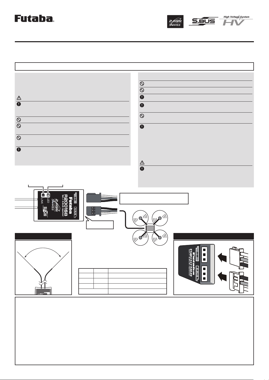
R2001SB
Link switch
Antenna
LED
S.BUS Port
CH3 output conventional system
/ Battery terminal
Antenna installation precaution
Do not cut or bundle the receiver antenna wire.
Do not bend the coaxial cable. It causes damage.
The antenna should not be pulled.
Keep the antenna as far away from the motor, ESC
and other noise sources as you possibly can.
Do not touch the antenna to metal, carbon, or other
conductive material.
Be sure that the two antennas are placed at 90
degrees to each other.
• The R2001SB has two antennas. In order to maximize signal
reception and promote safe modeling Futaba has adopted a diversity
antenna system. This allows the receiver to obtain RF signals on
both antennas and fly problem-free.
Antenna installation for carbon fuse
WARNING
The antenna portion of 30mm tip must be fully
exposed.
• Please make sure that the exposed portion won't slide back in the
fuse due to wind pressure or other force during the flight session.
S.BUS equipment
The power supply from S.BUS port is
also possible.
Antenna installation
90˚
Please refer the table below for LED status vs
receiver's condition.
LED Indication
Green Red Status
Off Solid No signal reception
Solid Off Receiving signals
Blink Off Receiving signals but ID is unmatched
Alternate blink Unrecoverable error (Memory, etc.)
R2001SB Specications
S-FHSS 2.4GHz system/S.BUS port and 1 channel for conventional system receiver
• Dual antenna diversity
• Size: 0.83 x 1.65 x 0.21 in. (21.1 x 41.8 x 5.3 mm)
• Weight: 0.15 oz. (4.2g)
* Be sure that when using ESC's regulated output the current capacity
of the ESC meets your usage condition.
* The Battery F/S voltage is set for 4-cell NiCd/NiMH battery. Bat-
tery F/S function doesn't work properly when a different type
of battery is used.
* The fail safe function can be set for each channel. However, it dif-
fers according to the transmitter. When you use TM-FH RF Module,
the fail safe function can be set for channel 3 only.
• Power requirement: 4.8V to 7.4V
• Battery F/S Voltage: 3.8V
* S.BUS port: R2001SB can be used with up to 8 channels. However,
it differs according to the transmitter. An unused channel is a neutral
signal. The F/S setting channel at F/S is F/S position. Another, it is
Hold signal.
Direction of the connectors
Page 2
Link to the transmitter
1
Bring the transmitter and the receiver
close to each other, within 20 inches (half
meter).
2
Turn on the transmitter.
3
Turn on the receiver.
4
Press and hold the Link switch more
than two (2) seconds. When the link is
complete, the LED in the receiver changes
to solid green. When the ID cannot be
read due to the surrounding environment,
try reading it with the transmitter and
receiver antennas touched.
What is S.BUS?
Different from conventional radio control systems, the S.BUS
system uses data communication to transmit control signals
from a receiver to a servo, gyro, or other S.BUS compatible
devices. This data includes commands such as “move the
channel 3 servo to 15 degrees, move the channel 5 servo to
30 degrees” to multiple devices. The S.BUS devices execute
only those commands for their own set channel. For this
reason, it can be used by connecting multiple servos to the
same signal line.
• When you use TM-FH RF Module, the fail safe function can be set
for channel 3 only.
• If there are many S-FHSS systems turned on in close proximity, your
receiver might not link to your transmitter. In this case, even if the
receiver's LED stays solid green, unfortunately the receiver might
have established a link to one of other transmitters. This is very
dangerous if you do not notice this situation. In order to avoid the
problem, we strongly recommend you to double check whether your
receiver is really under control by your transmitter by giving the stick
input and then checking the servo response.
WARNING
Do not perform the linking procedure with the
motor's main wire connected or the engine operating
as it may result in serious injury.
When the linking is done, please cycle receiver
power and check if the receiver to be linked is really
under the control of the transmitter to be linked.
WARNING
Turn on the power on transmitter → receiver in
order. In addition, always check the operation of all the
functions before flight.
WARNING
Do not insert or remove the S.BUS connector while
the receiver power is ON.
Since the S.BUS servo switches the operation mode automatically
according to the type of signal (S.BUS signal/PWM signal) from the receiver, if the connector is inserted or removed while the power is ON, an
S.BUS connected servo will be erroneously recognized and may stop.
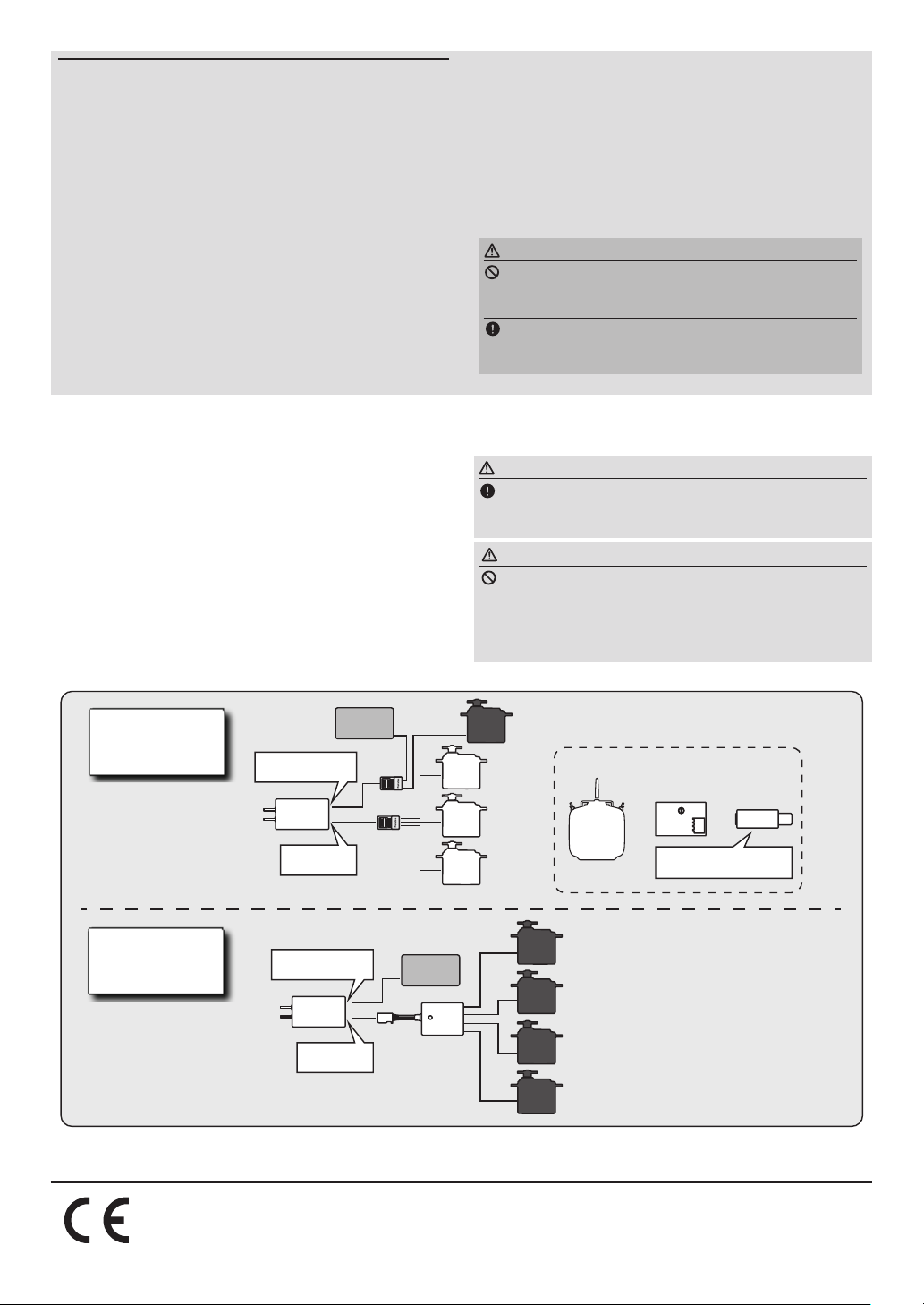
●Can also be used together with conventional servo.
S.BUS servo CH setting device
or or
SBC-1
Drivers and Link programs
"S-Link" must be installed.
conventional servos with the S.BUS system.
*Before installing the SBD-1 to the fuselage, set each channel at
each servo connector (SX1~3). Use the SBC-1 S.BUS channel
changer or CIU-2/3 USB adapter (S-Link software for setting) to
set the channel.
*Refer to the instruction manual of each item for the
setting method.
Conventional
Servo
Conventional
Servo
Conventional
Servo
Conventional
Servo
Transmitter
with S.BUS
setting
●The SBD-2/SBD-1 is a converter for using
◆SBD-2
Eight servos are connectable.
◆SBD-1
Three servos are connectable.
(Only 3 channel)
CIU-2/3
S.BUS
Servo
S.BUS
Servo
S.BUS
Servo
Conventional
Servo
Connection
by S.BUS
system
3/B:Conventional
CH3 Port
R2001SB
Receiver
S.BUS Port
Battery
Hub
Hub
Connecting
conventional
servo to S.BUS
©FUTABA CORPORATION 2016, 12 (1)
3/B:Conventional
CH3 Port
R2001SB
Receiver
S.BUS Port
1080 Yabutsuka, Chosei-mura, Chosei-gun, Chiba-ken, 299-4395, Japan
Phone: +81 475 32 6982, Facsimile: +81 475 32 6983
Battery
SBD-2
FUTABA CORPORATION
 Loading...