

Page 1
• No part of this manual may be reproduced in any form without prior permission.
• The contents of this manual are subject to change without prior notice.
• This manual has been carefully written. Please write to Futaba if you feel that any corrections
or clarications should be made.
Before using your new 2.4GHz system, please read this manual thoroughly and use the
system properly and safely. After reading this manual, store it in a safe place.
1M23N17303
Contents and Technical Specications
Your 2.4GHz system includes the following components;
Installing the PK-FSM2.4G/R603FS
[Specication]
• Communication method: One-way operation system
• Mode: PPM, HRS (Auto-detect)
• Maximum operating range: 80m (Optimum condition)
• For safety: F/S, B-F/S, ID (About 4billion ways of pair identications)
PK-FSM2.4G;
• Transmission antenna: 1/2λ mono-pole
R603FS;
• Reception antenna: Diversity type (Two antennas: internal
and external)
• Power requirement: 6V Nicd battery
• DSC function available
• RS232C port: (for factory use only)
• Size: 39x26x14mm (excluding a projection part)
• Weight: 14.1g
PK-FSM2.4G Module
2.4GHz System
PK-FSM2.4G Module and
R603FS Receiver
Thank you for purchasing a PK-FSM2.4G module and an R603FS receiver. This system is
based on the combination of the newly developed 2.4GHz module and its correspondent
receiver. The system utilizes the 2.4GHz-SS radio communication and an ultra small antenna.
In addition, the system inherits Futaba's unique HRS (High Response System).
Features
2.4GHzSS (Spread Spectrum) radio communication system
Frequency channel setting unnece ssary: Sifting the channels within the 2.4GHz band
automatically, this system minimizes the interference from other 2.4GHz system.
Accepts no unwanted signals by using ID code
The function “Auto-Detect” is utilized to automatically determine which mode is active,
HRS or PPM mode. (R603FS)
Short and small antenna (PK-FSM2.4G)/Diversity antenna (R603FS)
•
•
•
•
•
Applicable system; T3PK or T3VC Transmitter
R603FS Receiver
Module Cover for T3PK
Mini screwdriver
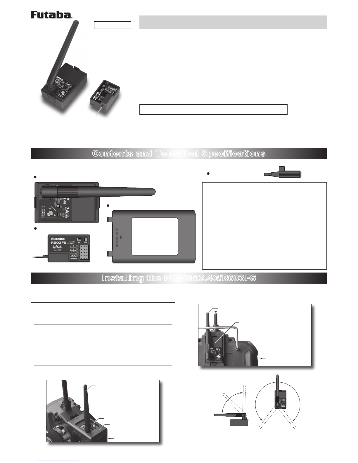
Install and adjust the PK-FSM2.4G module and R603FS receiver as described below.
Attachment of the module
CAUTION
Be sure to turn off the power of the transmitter before you attach
or detach the module.
1
Insert the module with care so that the connector pins of the
transmitter won't be bent.
WARNING
Adjust the antenna vertically to the ground. Otherwise, the operating range may become shorter.
T3PK Transmitter
PK-FSM2.4G Module
Antenna
Module Cover
T3VC Transmitter
PK-FSM2.4G Module
Antenna
0
1
2
3
4
5
6
7
8
9
(Antenna Moving Range)
0
1
2
3
4
5
6
7
8
9
I
NSTRUCTION
M
ANUAL
For cars only
Page 2
Usage Precaution
WARNING
Special attention should be paid before turning on the system
while other cars are running or other airplanes are flying be-
cause the 2.4GHz RC system could potentially affect them.
WARNING
Be sure to set the Fail Safe function.
Repair Service
Before requesting repair, read this instruction manual again and recheck your
system. Should the problem continue, request repair service as follows:
Describe the problem in as much detail as possible and send it with a detailed
packing list together with the parts that require service.
•
Symptom (Including when the problem occurred)
• System(Transmitter, Receiver, Servo's and model numbers)
• Model (Model name)
• Model Numbers and Quantity
• Your Name, Address, and Telephone Number.
If you have any questions regarding this product, please consult your local
hobby dealer or contact the Futaba Service Center.
FUTABA CORPORATION Phone: (043) 296-5118 Facsimile: (043) 296-5124
Makuhari Techno Garden Bldg., B6F 1-3 Nakase, Mihama-ku, Chiba 261-8555, Japan
©FUTABA CORPORATION 2006, 09 (1)
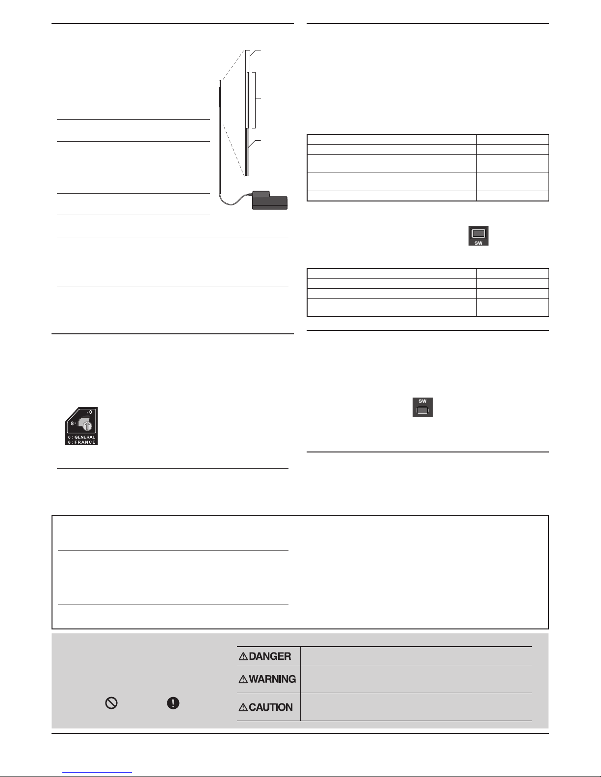
Receiver installation
Antenna
tube
Antenna
Coaxial
cable
R603FS
1
Install the R603FS receiver on the
car as follow;
Note: Th e op er at ing ra nge may be come
shorter, although depending on where
th e rec ei ve r and the anten na ar e
mounted.
WARNING
Install the antenna in the higher place as
shown in the figure.
Do not cut the antenna.
Keep the antenna away from the motor,
ESC and other noise sources as pos-
sible as you can.
Put the antenna in the antenna tube to
protect it.
Do not bend the coaxial cable. It causes
damage.
Wrap the receiver with something soft such as foam rubber to
avoid vibration. If there is a chance of getting wet, put the receiv-
er in a waterproof bag or balloon to avoid water.
CAUTION
Always use R603FS under the following conditions;
Power supply; 6V Nicd battery (PPM/HRS mode)
Servo; 6V type Futaba Digital Servo (HRS mode)
*
If the conditions are different, control is impossible or the servo may be damaged.
Frequency Range Setting
The frequency range of 2.4GHz system differs according to regulations
of the country that it is used in.
1
Use the r otar y swi t che s of the modu l e to sele ct t he
frequency range mode.
0
1
2
3
4
5
6
7
8
9
0: GENERAL
(2405.376MHz - 2477.056MHz)
8: FRANCE
(2407.424MHz - 2450.432MHz)
WARNING
If using this system in France, always use it to set the rotary
switch to "8".
* In other countries, both "0:GENERAL" and "8:FRANCE" are available.
How to turn on the power
A certain ID number is given to the receiver automatically. Identifying
this ID number, the system will minimize the interference from other
transmitters.
1
Bring the transmitter and the receiver close to each other
within one meter.
2
Turn on the transmitter.
Note: Check the LED on the module.
Parameter check for 0.5 seconds after power-on Red: On
Transmitting signals Green: On
F/S is activated by the tactile switch of the mod-
ule. (PPM mode)
Green: Blink
Unrecoverable failure (EEPROM, etc.)
Red and Green turn
on alternatively.
PCM is improperly selected. Red: Blink
3
Turn on the receiver.
4
Push the tactile switch of the receiver.
Note: Check the LED of the receiver.
No signal reception Red : On
Receiving signals Green: On
Receiving signals, but ID is unmatched. Green: Blink
Unrecoverable failure (EEPROM, etc.)
Red and Green turn
on alternatively.
How to Set the F/S Position
PPM mode only:
*HRS mode: Set the F/S function by the transmitter.
1
Move and hold the throttle trigger (stick) to the F/S servo
position where you want to set (slow side) then push the
tactile switch on the module.
The LED blinks green.
Note: Always set again when turning on the power.
Battery F/S function
The Battery F/S function becomes acti ve when the voltage of the
receiver becomes 4.75V or less. The throttle servo move to the preset
position.
Special Markings;
Pay special attention to the safety at
the parts of this manual that are
indicated by the following marks.
[Symbol] ; Prohibited ; Mandatory
Mark Meaning
Procedures which may lead to a dangerous condition and cause
death or serious injury to the user if not carried out properly.
Procedures which may lead to a dangerous condition or cause death
or serious injury to the user if not carried out properly, or procedures
where the probability of superficial injury or physical damage is high.
Procedures where the possibility of serious injury to the user is
small, but there is a danger of injury, or physical damage, if not
carried out properly.
 Loading...