

Page 1
Futaba
DIGITAL PROPORTIONAL
RADIO CONTROL
Page 2

Thank you for purchasing a Futaba digital
proportional radio control set.
Please read this manual carefully before using
your set.
CONTENTS
•FEATURES............................... 1
•CONTENTS
•TRANSMITTER CONTROLS
•
Inside
•OPERATION
•Transmitter
•CHARGING OF TRANSMITTER AND
DECEIVER Ni-Cad BATTERIES
•TRAINER
•STICK
•RECEIVER, SERVO, SWITCHES, AND Ni-Cad BATTERY
CONNECTIONS AND USAGE PRECAUTIONS ....
•SPLINED HORN............................ 12
•Futaba
•FP-130
•GUARANTEE
AND
RATINGS.
Rear
Trimmer
RF module
................................ 9
MECHANISM
Digital Proportional Frequencies
EXPLODED VIEW
Panel
........................... 5~8
AND
.............................
................... 2
................ 3
..................... 4
....................... 8
................ 8
ITS
ADJUSTMENT ....... 9
............
.....................
~4
10~11
12
13
13
Page 3

• FEATURES
The FP-7FGH was specially developed for model helicopters.
Please read this manual carefully before using your new set.
•RF module systems allows one-touch changing of the frequency band.
•Aileron
and quarter scale models and gliders.
•Servo reversing switch for each channel allows
reversing of the servo direction by simply flipping a switch.
•Two
tor, and rudder channels. Aileron and elevator
dual rate can be switched simultaneously or
independently.
•Newly
stick with adjustable tension and lever head.
•Pitch control -> rudder and throttle ->> pitch
control mixing.
•Throttle hold function for auto-rotation.
•High and Low pitch cab trimmer permits ad-
justment of the best pitch for hovering and
maneuvering.
•Idle
aerobatics.
•Throttle High and Low ATL (Adjustable
Throttle Limiter) allows simple, reliable throttle
linkage hook-up.
•ATV (Adjustable Travel Volume) on AILER-
ON, ELEVATOR & RUDDER channels allows
independent adjustment of the servo left. right,
up. and down throw.
•Trainer system offers an easy training of flight
for beginners. FM systems are not compatible
with AM systems.
•Highest
phisticated designs. The transmitter fits easily
into your hand.
•Neck strap supplied as a standard accessory.
This transmitter has numerous functions which
can be easily operated when using the neck
strap.
to
kinds
designed
up
functions
quality
rudder mixing
of
dual
rates
case
and new open gimbal
used
for
aluminum
is
ideal
on the
static
case
for
giant scale
aileron,
and
dynamic
featuring
eleva-
so-
•Selective squelch circuit is unaffected by other
transmitters on other bands during simultaneous multi-band flights.
•Futaba custom 1C and large capacity capacitor
improve stability against power supply voltage
fluctuations tremendously.
•Same antivibration metal plated
as
the high-quality J Series.
•Throughole printed circuit board is invul-
nerable to shock and vibration.
pin connectors
SERVO FP-S130
•Small, high-quality five-pole micromotor servo.
High-torque 55.6 oz-in (4 kg-cm). high-speed
(0.24
sec/60°), watertight.
•New indirect drive potentiometer improves
vibration and shock resistance and neutral precision.
•Futaba low-power custom 1C provides high
starting torque, narrow dead band, and superior
trackability.
•Fiberglass reinforced PBT (polybutylene tere-
phthalate) injection molded servo case is mechanically strong, and invulnerable to glow fuel.
•Strong polyacetal resin ultra-precision servo
gear features smooth operation, precise neutral,
and very little backlash.
•Thick
film
gold plated connector pins
positive contact and improved reliability against
shock and vibration. The housing is polarized to
prevent reverse insertion.
•Four
special
available.
adjustable splined
horns
ensure
are
1
RECEIVER FP-R107M
•Pulse noise rejection circuit is invulnerable to
noise.
•Small & high sensitivity 7 channel FM receiver
using a specially developed high sensitivity
monolithic 1C IF amplifier.
Page 4

• CONTENTS AND RATINGS
Ratings and specifications are subject to change without prior notice
Model
Transmitter
Receiver
Servo
Switch
Ni-cd battery
Accessories
Charger, extension cord, frequency flag, spare horn, neck strap, mounting screws
Transmitter FP-T7FGH Servo FP-S130
Operating system
Transmitting frequency
Modulation
Power requirement
2
Current drain
: Two-stick, 7 channels for
F3C helicopter
: 72MHz band
27, 29, 35,
MHz band switching possible by changing RF
module.
:
FM
: 9.6V, 8/500mAH inter-
nal ni-cd battery.
: 150mA
40,
72 & 53
FP-7FGH
FP-T7FGH x 1
FP-R107M x 1
FP-S130x4
SWH-5 (R4-SWJ)
NR-4Jx 1
Control system
Operating angle
Power requirement
Current drain
Output torque
Operating speed
Dimensions
Weight
+ pulse width control
1520uS.N
One side 45° or more (including trim)
4.8V (shared with
receiver)
6.0V/8mA (at idle)
55.6 oz .in (4 kg-cm)
0.24 sec/60°
1.52x0.77x 1.36in.
(38.5x 19.5 x 34.5mm)
1.48 oz (42g»
Receiver FP-R107M Charger FBC-2 (A)
Receiving frequency
Crystal change system
Intermediate frequency
Power supply
Current drain
Dimensions
Weight
Receiving range
27,29, 35, 40, 72 & 53MHz.
Precision crystal that permits
frequency change within the
same band.
455kHz
4.8V
Ni-Cad battery, shared with receiver
15mA
1.69 x2.72x0.79in.
(43 x 69 x 20mm)
1.9oz (54g»
500m on the ground, 1000m or
greater in the air when used
with the FP-T7FGH.
Input voltage
Output
Receiver and servo Ni-Cad battery NR-4J
Voltage
Dimensions
Weight
120VAC,50/60Hz.
4VA
Txside9.6V.45mA
Rx side 4.8V, 45mA
4.8V,4/500mAH
2.01 x 2.28 x 0.59in.
(51
x58 x 15mm)
3.35oz (95g)
Page 5
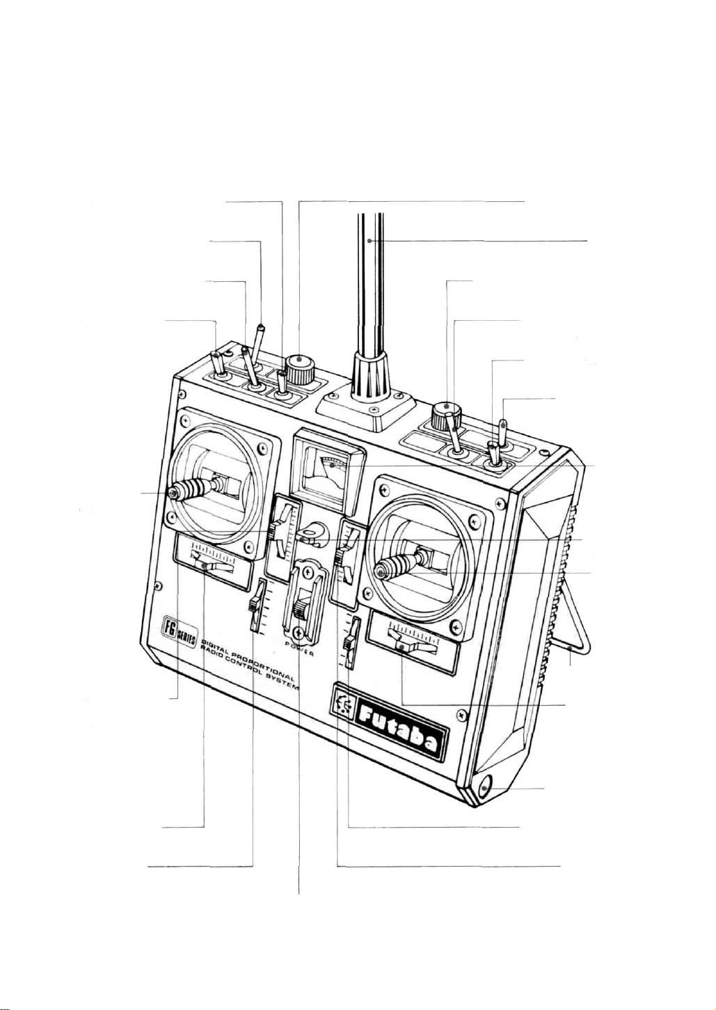
•TRANSMITTER CONTROLS
Names and functions of transmitter controls
161 dle-up ON-OFF switch
18 Throttle hold switch
19 Rudder dual-rate or
VTR on/off switch
5 CH5 landing
gear switch
(rate gyro output
switch)
(3)Throttle
4 Rudder
stick
17 Idle-up trim control
22 Antenna
15Throttle-rudder mixing knob
13 Elevator dual-rate or
VTR on/off switch
12Aileron dual-rate or
VTR on/off switch
14Trainer switch
21
Square
level meter
25 Hook for
neck strap
1 Aileron
2 Elevator
stick
10 Throttle trim
with ATL
(Adjustable
Throttle Limiter)
11
Rudder
(7 CH7 lever
trim
20 Power switch
24
Handle/stand
8 Aileron trim
23 Antenna storage
6 Pitch trim/C H6 lever
9 Elevator trim
Fig.1
Page 6

Left side
Fig. 2
26 Transmitter
NiCad battery
charging jack
27Trainer cord socket
Inside Rear Trimmer Panel
1 Aileron
ATV left-side trimmer
2 Aileron ATV right-side trimmer
5 Aileron -> rudder mixing left-side trimmer
6 Aileron -> rudder mixing
right-side trimmer
8 Elevator ATV
down-side
trimmer
9 Elevator
ATV
up-side
trimmer
28Transmitter
RF module
29 Trimmer panel
Fig. 3
Opening the trimmer panel
Fig. 4
Open by pulling in the arrow direction.
12 Throttle hold point trimmer
15 Rudder ATV left-side trimmer
16 Rudder ATV right-side trimmer
19 Pitch control low-side trimmer
20 Pitch control high-side
trimmer
22 Servo reversing
switches
10 Elevator dual rate trimmer
7 Aileron <-> rudder mixing ON-OFF switch
4 D DR<->VTR switch
3 Aileron dual rate trimmer
17 Rudder dual rate trimmer
14Throttle -> rudder mixing ON-OFF switch
13 Throttle high-side ATL trimmer
11DR->VTR switch
21Throttle -> Pitch control
mixing ON-OFF switch
18 DR->VTR switch
Fig.
5
Page 7

• OPERATION
This section explains the operation of the transmitter controls when the servo reversing switches are in the normal position. When the revers-
ing switches are in the reverse position, opera-
tion is the opposite of that described here.
CD Aileron stick Controls the ailerons.
2 Elevator stick Controls the elevators.
3 Throttle Stick Controls the throttle.
4 Rudder Stick Controls the rudders.
5 CH5 switch Switches the rate gyro output.
6 Pitch trimmer/CH6 lever Trims the pro-
peller pitch control independently from the
throttle.
(7)CH7 lever Spare channel.
8 Aileron trim lever Aileron trimmer.
9
Elevator
10 Throttle
travel
only when the throttle stick is at the low side as
shown in Fig. 6. It is very convenient because
the high side of the throttle position remains
unchanged even when the low side is adjusted.
trim
trim
lever
trim
lever
lever. This
Elevator
w/ATL
lever
acts
trimmer.
Adjustable
as a trimmer
12
Aileron dual rate switch Aileron dual
rate ON-OFF switch. When set to the upper position, dual rate is turned on, and when set to
the lower position, dual rate is turned off. At
dual ON. the deflection can be set as shown in
Fig. 7 with the aileron dual rate trimmer
located on the trimmer panel at the back of the
transmitter. At dual OFF, the operating linearity
can be switched as shown in Fig. 8 with the
VTR (Variable Trace Ratio) switch also located
on the trimmer panel.
Neutral
Deflection is
adjustable
from 40% to
100%
of
the
total travel
Aileron servo
within this
range.
5
Fig.
7
DR side VTR side
Servo throw by
throttle trimming
(30% of total
travel)
11 Rudder trim lever Rudder trimmer.
*Trim lever is used for fine adjustment.
The trim lever is used for neutral position adjustment or correction of the posture of the aircraft after
installation is completed. However, after test flight, try to keep the neutral position as they are making necessary corrections with the rod adjusters, etc.
Servo throw by
throttle stick
Fig.
6
N
Stick deflection N Stick deflection
Fig.
8
Page 8

13 Elevator dual rate switch • Elevator dual
rate ON-OFF switch. Simitar to aileron dual
rate, (dual rate ON) the elevator deflection can
be adjusted with the elevator dual rate trimmer
10 and the servo operating linearity can be
switched with the DR <-> VTR switch 11.
14
Trainer switch Pull on/self-off switch. The
transmitter connected by the trainer cord (MTC) operates and when it is OFF, your-own
transmitter only operates.
15 Throttle-rudder
mixing
knob
Ratchet
knob that sets the throttle to rudder mixing
amount and direction. Mixing amount is 0 —
50%.
16
Idle-up ON-OFF switch This switch is
turned ON when pushed forward.
Throttle servo
l7 and the servo operating linearity can be
switched with the DR <-> VTR switch 18 .
Other functions are the same as those of the
aileron dual rate switch.
20 Power switch
21
Square level meter Level meter indicates
the transmitter output power and indirectly
shows power supply voltage.
22
Antenna
23
Antenna storage The opening is used for
storage of the antenna while carrying the transmitter. It is located at the bottom right side of
the transmitter.
24 Handle/stand
25 Hook for neck strap
26 Transmitter Ni-Cad battery charging
jack
27 Trainer cord socket
28 Transmitter RF module
29 Trimmer panel
6
Non-slip adjustable lever head
The length of the lever head is adjusted to
suit the operator.
Unlock lever head (A) and (B), by turning
them in the arrow direction, set head (A)
to the desired length, then relock the
Low
Idle up amount is adjustable within this
range with the knob 17
17
Idle-up
trim
control
Sets
the
High
Fig.
idling
9
speed
heads.
Lever head (A)
Lever head B
Fig.
10
when the 16 idle-up switch is ON.
18
Throttle hold switch When this switch is
set to ON, the throttle servo stops at the position set at the 12 trimmer and only the pitch
servo operates. This switch is used in auto-rotation
dives.
Both throttle
and
pitch
servos
mix-
ing is performed when this switch if OFF. It is
ON when pushed forward.
19
Rudder dual rate switch Rudder dual
rate ON-OFF switch. Similar to aileron dual
rate, at dual rate ON, the rudder deflection can
be adjusted with the rudder dual rate trimmer
Inside rear trimmer panel
1,2 Aileron ATV
(Adjustable Travel
volume) trimmer [2] RIGHT is for the right
aileron and 1 LEFT is for the left aileron.
The servo travel volume is independently adjustable to the left and right from the neutral
position. Travel adjustment ranges 0 to 100%.
Page 9

Neutral
Right
Adjustable with
rudder ATV right
knob (right full
Aileron)
Adjustable with the
rudder ATV left
knob (left full
Aileron)
Aileron servo Fig. 11
Left
3 Aileron dual-rate trimmer adjusts the
aileron travel when the 12 aileron dual-rate or
VTR switch ON. Travel adjustment ranges 40
to
100%.
4 DR (dual-rate) <-> VTR (Variable Trace
Ratio) switch
5 6 Aileron-rudder MIX trimmer (From
aileron to rudder) Adjust the mixing volume
and the mixingdirection of rudder. After linkage
is completed adjust the MIX direction and
amount with trimmers. MIX amount adjustment ranges 0—100% each, the same adjustment can be done even if the servo is reversed.
7 Aileron -> rudder mixing ON-OFF
switch
8 9 Elevator ATV trimmer 9 UP is for up
and 8 DOWN is for down. The adjustment
range is same as the aileron ATV.
10
Elevator dual-rate trimmer adjusts the
elevator travel when the 13 elevator dual-rate
or VTR on/off switch is
ON.
11 DR <-> VTR switch
12 Throttle hold point trimmer This trim-
mer
sets
the throttle
servo
stop
point
when the
throttle hold switch 18 is set to ON. When the
trimmer is turned counterclockwise, the throt-
tle servo moves to the stow side.
13
Throttle high side ATL trimmer This
trimmer adjusts only the high side of the throt-
tle stick. It is extremely convenient when con-
necting the linkage, since the low side remains
unchanged even when the throttle high side is
adjusted with this trimmer.
Throttle servo
Fig.
12
14 Throttle -> Rudder mixing ON-OFF
Switch This switch turns mixing from the
throttle control (channel 3) to the rudder
(channel 4) ON and OFF.
15 16 Rudder ATV trimmer. The adjust-
ment range is same as the aileron ATV.
17
Rudder
dual-rate
trimmer
Rudder dualrate or VTR trimmer adjusts the rudder travel
when the 19 rudder dual-rate or VTR on/off
switch is ON.
18 DR <-> VTR switch
19,20
Pitch
control
trimmer
The
servo
throw
can be varied from 0 to 100% of the total. Set
for
optimum pitch during normal flight.
20 Pitch control
high side
trimmer
High pitch can be
adjusted within
this range.
Pitch control servo
19 Pitch control
low side
trimmer
Low pitch can be
adjusted within
this range.
Fig. 13
21Throttle -> Pitch control mixing ON-
OFF switch This switch turns mixing from
the throttle control (channel 3) to the pitch
control (channel 6) ON and OFF.
7
Page 10

22 Servo reversing switches These switches
reverse the direction of the servos. It is very
convenient when connecting the linkage.
43 CH7 lever channel
42 CH6 pitch control
41CH5 switch channel
Transmitter RF module
Change this module to switch to any frequency among 27, 29. 35, 40. 53 & 72
MHz bands.
Transmitter
I
6
37 Aileron
38 Elevator
[39]
Throttle
40 Rudder
NORM: Forward
REV: Reverse
Fig. 14
Remove the module by
pulling it forward while
pressing this tab inward.
Fig. 15
CHARGING OF TRANSMITTER AND RECEIVER
Ni-Cad BATTERIES:
8
Charger
FBC-2
NR-4J
Fig.
16
RX
AC-110V
(220V, 240V)
TX
Charging plug
•Connect the charging plug of the FBC-2 charger to the transmitter charging jack, connect the
3P connector of the FBC-2 to the receiver NiCad battery NR-4J, and plug the FBC-2 to a
110VAC (220V,240V) outlet as shown in this
figure. The TX and RX charging LED light; indicating that the batteries are being charged.
•The
times at 10 minutes per flight between rechargings.
•Charge the batteries for about 15 hours. When
the set is not in use for some time, repeat discharge and charge, two to three times before
use. (If the batteries are not used for a long
time, their capacity will go down).
•FBC-2 charges transmitter and receiver Ni-Cad
batteries independently or simultaneously.
Receiver
Recharge the receiver and
transmitter Ni-Cad
batteries as shown
battery
can
be
used
in Fig.
16
about 10
Page 11

TRAINER
Connect the transmitters with the trainer cord
(M-TC, purchased separately) as shown in Fig.
When the switch is in the ON (pull) position,
the student's transmitter operates and when the
switch is in the OFF position, the instructor's
transmitter operates. The transmitter at which
the trainer switch is operated on-off becomes
the instructor's.
(Power switch ON and transmitter operating)
Instructor transmitter
STICK MECHANISM AND ITS ADJUSTMENT
•The new gimbal is open. This
one has been used only for the
most expensive radio controls. It
also has the built-in tension adjustment mechanism on open
gimbal for the first time. You can
adjust tension of spring for your
best stick feeling.
•CP variable resistor improved the
neutral characteristics and resolu-
tion tremendously.
•All molded
grade polycarbonate that virtually
eliminates the effects of temperature and humidity.
parts
made
of
high-
•
Turn with a Phillips
screwdriver.
•When the core rises,
the spring tension
increases.
9
1 To adjust spring tension, remove
case back. Loosen and remove
screw 1 &
from bottom side first.
2 Adjust spring tension with
Phillips screw driver at opening
A, B, C for MODE II transmitters.
2 .
Lift
off
case back
Fig. 18
Module OFF
A
B
C
AD
Page 12

• RECEIVER, SERVO, SWITCHES, AND Ni-Cad BATTERY
CONNECTIONS AND USAGE PRECAUTIONS
The parts inside
the dotted
lines are sold
separately.
CH7 servo
Pitch control servo
(Landing gear servo)
10
Received crystal
FP-R107M 7 channel FM receiver
Antenna
R4-SWJ
Extension
cord
Charging plug
Landing gear
adapter
(Landing gear servo)
When a rate
Rudder
servo
Throttle servo
Elevator servo
Aileron servo
is used, this servo
connects to the
receiver through
the rate gyro.
gyro
Fig.
20
Page 13

Rate gyro FP-G152
Connected servo (rud-
der servo for helicopter)
neutral position trim-
mer (This trimmer is
operative even when
the control box power
switch is set to OFF.)
Connect to receiver
retract or
auxiliary
channel
(for gyro
sensitivity switching)
for Receiver
Five battery pack 6V connector Motor regulated
power supply. (Insert the jumper connectors when
the power supply is shared with the receiver.)
Gyro output polarity switch
Control amp
Gyro body
Control box
Jumper
connector
Remove
these
screws.
and
remove
the
case.
Gyro output
trimmer
Fig.
21
•Connect the servos and switches firmly as
shown in Fig. 20. Then extend the transmitter
and receiver antennas fully.
•Set the transmitter power switch to ON. then
set the receiver power switch to ON. The servos
stop near the neutral position. Operate the
transmitter sticks and check if the corresponding servos faithfully follow operation of the
sticks.
•After setting the pushrods at the servo horns,
check that the direction of operation of the
transmitter sticks and the direction of operation of the rudders are the same.
•Operate each servo horn over its entire operating range and check if the pushrod binds, or is
too loose. Applying unreasonable force to the
servo
horn
will
adversely
affect the
servo
and
quickly drain the batteries. Always make the
operating width of each rudder somewhat larger
than the full stroke (including trim) of the
servo horn. Adjust the servo horns so that
operate
smoothly
even
when the
trim
lever
and
stick lever are operated simultaneouly in the
same direction.
•Be alert for noise.
If engine vibration causes metal parts to touch,
noise will be produced and the receiver and
servos may operate incorrectly. We recommend
the use of noiseless parts.
•When installing the switch, cut a rectangular
hole somewhat larger than the full stroke of the
for Rudder Servo
switch and install the switch so it moves smoothly from ON to OFF. When the switch is
mounted inside the fuselage and is turned ONOFF with wire, install the switch mount as
described above. Install the switch where it will
not come into direct contact with engine oil,
dust, etc.
•Even though the receiver antenna is long.
do
not cut or bundle it.
•The
servos,
Ni-Cad
battery,switches,extension
cords, and crystals of FP-7FGH are the same
as those of the high-quality J Series. The crystals
are extremely precise and are identified by
color (red and green). Use Tx and Rx crystals
of the same color.
•A spare horn is supplied. Use it as needed.
•Wrap the receiver in sponge rubber. Place the
receiver in a plastic bag and wrap a rubber band
around the open end of the bag to waterproof
and dustproof the
receiver.
Do
the
same
with
the receiver/servo battery.
•Use the rubber bands wrapped
around the
receiver to hold the servo and switch leads.
•After mounting is complete, recheck each
part, then make the transmitter antenna as
short as possible, extend the receiver antenna
fully,
and
operate
the
set
from a distance
of
20m to 30m. The movement of each rudder
(servo) should faithfully follow the operation
of each stick of the transmitter.
11
Page 14

SPLINED HORN
This horn permits shifting of the
servo neutral position at the servo
horn. Setting
and shifting the
neutral position
a) Angle divisions
Fig.
22
1) The splined horn has
25
seg-
ments. The amount of change per
segment is;
2) The minimum adjustable angle
is determined by the number of
arms or number of the holes. For
four arms,the minimum adjustable
angle is:
12
horn A
(FSH-6X)
b) Effect
Baseline A
Fig.
23
To shift the holes center line to
the right (clockwise) relative to
baseline A, shift arm 2 to the position of arm 1 and set it to the
position closest to baseline A.
[Example] For a four arm horn,
the angular shift per segment is
14.4°. The shift to the right is 90°
- (14.4 x6) =3.6°
To shift by the same
opposite direction, use the
angle in the
oppo-
site arm number.
horn B
(FSH-6S)
horn C
(FSH-6R)
Fig.
24
For a six arm horn, turn the arm
counterclockwise and set arm 2
to the position of arm 1. The adjustable angle is 60° - (14.4 x 4)
=2.4°.
Arm 3 shift 4.8° to the right, arm
6 shifts 2.4° to the left,and arm 4
shifts 7.2° to the right and left.
Fig.
25
horn D
(FSH-6W)
Fig.
26
Futaba
•The
frequency of Futaba
sets
can
the 27MHz band only.
•However, a 27MHz band set cannot be changed
to 72MHz band, and vice versa.
•Therefore, always attach the correct frequency
flag to the end of the transmitter antenna.
Each frequency band has its own designated
color, as stated above. The frequency flag is
intended for identification purposes.
•Also
change
is changed.
•Futaba paired crystals are precisely matched.
Always use a Futaba crystal set (transmitter,
receiver) when changing the frequency.
•It
is illegal to change crystals of transmitter
the 72-75MHz bands in the U.S.A.
Digital
be
changed among bands
the frequency flag when frequency
Proportional
digital
proportional
(1)~(6)
Frequencies
on
Frequency Channel No. Flag Color
26-27MHz -
26
995
27.045
27.095
27.145
27.195
27.255
72/75MHx • Aircraft only 'Shared
72.030
72.080
72.160
on
72.240
72.320*
72.400
72550
72.590
72
.630
72.670
72.710
72.750
72.790
72330
72.870
72.910
72.960*
75.640
Aircraft/
12
—
—
-
38
40
42
44
46
48
50
52
54
56
—
-
(FOR
U.S.A.)
Car/Boat
Brown
Red
Orange
Yellow
Green
Blue
Brown-Red
(Top Flag/Ribbon-
Bottom Flag/Ribbon)
White/Brown
White/Blue
White/Red
White/Purple
White/Orange
Orange-Grey
Yellow-Black
Yellow-Red
Yellow-Yellow
Yellow-Blue
Yellow-Grey
Green-Black
Green-Red
Green-Yellow
Green-Blue
White/Yellow
White/Green
75MHz-
75.430
75.470
75510
75.550
75.590
75.670
75.710
75.750
75.790
75
.830
75.870
53MHz
License
53.100
53.200
53.300
53.400
53500
53.600
53.700
53.8OO
Car& Boat
62
64
66
68
70
74
76
78
80
82
84
Aircraft/Ca
Required
—
—
-
—
—
only
Blue-Red
(Top Flag/Ribb
Bottom Flag/R
Blue-Yellow
Blue-Blue
Blue-Grey
Purple-Black
Purple-Yellow
Purple-Blue
Purple-Grey
Grey-Black
Grey-Red
Grey-Yellow
r/Boat - FCC Amatuer
Black/Brown
Black/Red
Black/Orange
Black/Yellow
Black/Green
Black/Blue
Black/Purple
Black/Grey
aon-
ibbon)
Not
generally
in
use
Page 15

FP-130 EXPLODED VIEW
No.
1.
Upper case FCS 30
2.
Middle case FCS-30
3.
Bottom case FCS 30
4.
Ball bearing S04130
5.
Potentiometer 139995
6.
VR drive plate S02753
Motor S91243
7.
8.
Motor pinion S02461
1st gear FGS30
9.
2nd gear FGS-30
10.
11.
3rd gear FGS 30
12.
Final gear FGS-30
13.
2nd shaft S02481
14.
Intermediate shaft S02480
Spacer washer 0.3T S02486
15.
Seal ring S90415
16.
17.
0-ring S90426
Servo horn D FSH-6W
18.
Horn mounting screw FSH-41
19.
20.
Printed wiring board S130 AS1220
Lead wire packing S90045
21.
22.
S130 3PB-WRB-300 FPC-8M
Screw 0-ring S90410
23.
24.
Case
S130 Nameplate S60101
25.
Part Name Part No.
mounting
screw
J50085
GUARANTEE
Your NEW FUTABA Digital Proportional R/C system is guaranteed against defects in
workmanship and material for 180 days from the date of purchase when the attached
registration card is returned to us within ten days of purchase.
This Guarantee is null and void if the R/C system has been improperly handled,
damaged in a crash, or tampered with and does not cover the replacement of plastic
housings or electronic components damaged due to the use of improper voltages.
When service is required, please take your equipment to your local authorized service
station or ship it directly to us. All postage, shipping, and insurance changes must be
paid by the user.
This guarantee only applies to the continental U.S.A., Hawaii, and Alaska.
Page 16

To insure prompt service, please follow the instructions qiven below.
1. Charge the batteries for at least 1 8 hours prior to shipment
2. Return the system only Not your complete installation Remove the servos from their mounts and remove the foam
padding from the receiver.
3.
Plugs or other modifications which interfere
your expense.
4. Carefully pack all components individually, using sufficient packing material to prevent damage during shipment.
5. Include a brief but thorough explanation of all problems and service required and tape it to the back of the transmitter Place a label describing the function of the servo on each servo
6. Be sure to Include your full address and tel. Mo.. zip code inside the box as well as on the outside.
7. Include a packing list of all items being returned, and double check to make sure that all items are packed.
8.
Upon
receipt
sent to you. Your equipment will then be repaired and returned to you upon receipt of payment or C.O.D, (cash).
This factory repair service applies only to the continental U.S.A.. Hawaii, and Alaska.
of
FACTORY REPAIR SERVICE
with
factory
your
equipment
at
the
Futaba
factory,
an
test
estimate
procedures
of
the
will
cost
be returned
of
repair
to
(over
factory
$25.00
standard at
only)
will
be
 Loading...