

Page 1
INSTRUCTION MANUAL
D60506
Futaba
DIGITAL PROPORTIONAL
RADIO CONTROL
FP-6VA
FM 6 CHANNEL
AIRPLANE R/C SET
FOREWORD
Thank you for selecting the Futaba SKYSPORT-6A.
The SKYSPORT-6A is an easy-to-use digital proportional R/C
set for all classes of R/C aircraft hobbyists, from beginners to
advanced pilots. It has an outstanding array of functions
needed by all classes of pilots.
To enjoy its functions to the fullest and to ensure safe flying,
please read this manual carefully before using your set.
After reading this manual, store it in a safe place. If you encounter any difficulties while using your set, please refer to the appropriate sections in this manual.
In addition to this manual, please read all of the manuals in-
cluded with your airplane, engine and other flight related equip-
ment you may use.
To help ensure safe use, pay particular attention to the precautions printed throughout this manual and indicated by an excla-
mation mark [!].
ATTENTION
1. Application of Product
This product is not intended for use in any application other
than for the control of models for hobby and recreational purposes. This product is subject to regulations of the Ministry of
Radio/Telecommunications and is restricted under Japanese
law to such purposes. The laws of other countries may similarly restrict the use of this product. Futaba is not responsible
for
any use that is not in compliance with applicable law.
2. Exportation of Product
If the product is exported from Japan, the prior approval of
the Ministry of Radio/Telecommunications is required regarding the country of destination. If this product is reexported
from other countries, it may be subject to restrictions on such
reexport and prior approval of government authorities may be
required.
3. Modification, Adjustment & Replacement of Parts
Futaba is not responsible for any use of this product that is
not in compliance with applicable law and disclaims all responsibility for any modification or alteration of the
product,including the incorporation of the product into other
products by third parties, that is not in compliance with applicable law.
THE FOLLOWING STATEMENT APPLIES TO THE RECEIVER:
THIS DEVICE COMPLIES WITH PART 15 OF THE FCC RULES. OPERA-
TION IS SUBJECT TO THE FOLLOWING TWO CONDITIONS:
(1)THIS DEVICE MAY NOT CAUSE HARMFUL INTERFERENCE, AND
(2) THIS DEVICE MUST ACCEPT ANY INTERFERENCE RECEIVED,
INCLUDING INTERFERENCE THAT MAY CAUSE UNDESIRED
OPERATION. (For U.S.A.)
1. No part of this manual may be reproduced in any form without prior
written permission.
2. The contents of this manual are subject to change without prior
notice.
3. This manual has been carefully written, but please feel free to write
to Futaba if you find that any corrections or clarification's that should
be made.
4. Futaba is not responsible for the results of the use of this product by
the customer.
5. Futaba and SKYSPORT are a registered trademark.
PRECAUTIONS
To use your R/C set safely, please observe the following precautions:
(Operating precautions)
[!] When powering up the system, first turn on the transmitter
power, then turn on receiver power. When powering down
the system, first turn off the receiver power, then turn off the
transmitter power. If the power is turned on or off in the reverse order the control servos may move erratically causing
engines or electric motors to race unexpectedly and possibly
resulting in serious injury to the user or bystanders. Before
turning on the power, set the throttle stick to the maximum
slow position.
[!] Extend the transmitter antenna to its full length. If the antenna
is not extended fully, the transmitter output will drop and the
range of receivable transmission will be shortened.
[!] Never fly two or more models on the same frequency at the
same time. Before flight, use a frequency monitor or other
device to check that the frequency is not in use. Simultaneous flight on the same band is extremely dangerous because it will cause interference and loss of control. Differences in modulation method or signal format (AM, FM, PCM,
etc.) does not mean that flights can be made on the same
band.
ATTENTION:
The product that you have purchased contains a
rechargeable battery. The battery is recyclable. At
the end of it's useful life, under various state and
local laws, it may be illegal to dispose of this battery
into the municipal waste stream. Check with your
local solid waste officials for details in your area for
recycling options or proper disposal.
[!] Do not forget to recharge the Nicd battery before each flight.
Needless to say, a dead battery will cause loss of control and
a crash. Always check the discharge time on the ground and
provide a margin of safety when determining the remaining
flight time. When recharging the Nicd battery, observe the
charging current and charging time specified on the battery.
Charging the battery at a current and time exceeding the
specified values will not only damage the battery by overcharging, but will also cause overheating and other dangerous conditions.
-1-
Page 2
[!] Do not fly on rainy days. Even in a drizzle, water can enter the
transmitter through the antenna and sticks and cause faulty
operation. The resulting loss of control may cause a crash
the engine to race and is very dangerous.
[!] When placing the transmitter on the ground during flight
preparations, make certain that the transmitter cannot be
easily toppled by the wind or other means. If it tips over while
the engine is running and the throttle stick is inadvertently
moved to the high position as result, serious injury to the operator or others could result.
[!] Always test your digital proportional R/C set before flight.
a simple test method, before starting the engine, retract the
transmitter antenna fully and operate each servo from a distance of about 5m and check if the servos follow the movement of their control sticks. If a servo does not follow the
movement of its control stick, extend the transmitter antenna
to its full length, increase the distance on the ground, and
repeat the test. If the receiving range is still short, discontinue
flight and check the set.
or
As
(Flying field)
[!] In general, when a model is flown at high speed and / or the
flying range is large, even more caution is necessary. A safe
method is to fly at an exclusive flying field belonging to a club,
etc. However, the presence of spectators, wind direction, etc.
must be constantly monitored. In areas near high tension
lines, high buildings, and communication facilities, consideration must be given not only to normal flight dangers, but also
to possible loss of control caused by radio wave interference.
Because R/C radio waves have a fairly long range, a location
at least 3 km / 2 miles from other R/C flying fields and R/C
control circuits is necessary.
SET CONTENTS
Set name
Transmitter
Receiver
Servos
Battery
(Transmitter)
Battery
(Receiver)
Battery charger
Others
FP-R116FB, FP-R138DF, or FP-R127DF
FP-S3001x4orFP-S148x4
Receiver switch, Extension cord,
Servo horns, Flat screwdriver
SKYSPORT-6A
FP-T6VA
NT-8iB
NR-4J
x1
RATINGS
Transmitter FP-T6VA
Operating system: Two-stick, 6 channels, w/airplane function
Transmitting frequency: 29, 35. 36, 40, 41, 50, 60 or 72MHz band
Modulation: FM (Frequency Modulation)
Power requirement: 9.6V Nicd battery(NT-8iB)
Current drain: 180mA
Receiver FP-R116FB
Receiving frequency: 29, 35. 36. 40, 41 or 60MHz band
Intermediate frequency: 455kHz
Power requirement: 4.8V or 6V Nicd battery (shared with servos)
Current drain: 22mA
Size: 33.4X50.4X20.5mm
Weight: 30g/1.06oz
Receiver FP-R138DF
Receiving frequency: 35MHz band
Intermediate frequency: 1st IF 10.7MHz. 2nd IF 455kHz
Power requirement: 4.8V or 6V Nicd battery (shared with servos)
Current drain: 12mA
Size: 65X36X21,5mm
Weight: 39g/1.38oz
Receiver FP-R127DF
Receiving frequency: 50 or 72MHz band
Intermediate frequency: 1 st IF 10.7MHz, 2nd IF 455kHz
Power requirement: 4.8V or 6V Nicd battery (shared with servos)
Current drain: 10mA
Size: 64.3X35.8X21.0mm
Weight; 40.5g /1.43oz
Servo FP-S3001/FP-S148
Control system: Pulse width control
Operating angle: One side 45 degree min. (including trim)
Power requirement: 4.8V or 6V Nicd battery (shared with receiver)
Current drain: 8mA (at idle)
Output torque: 3kg-cm / 42oz-in
Operating speed: 0.22 sec/60 degree
Size: 40.4x19.8x36mm
Weight: 45.1g / 1.59oz(S3001),44.4g/
Nicd battery NT-8JB
Voltage: 9.6V
Capacity: 500mAh
Nicd battery NR-4J
Voltage: 4.8V
Capacity: 500mAh
Dimensions: 51x58x15r
Weight; 95g/3.35oz
Product Support
(Do Not Remove From Department)
1.57oz(S148)
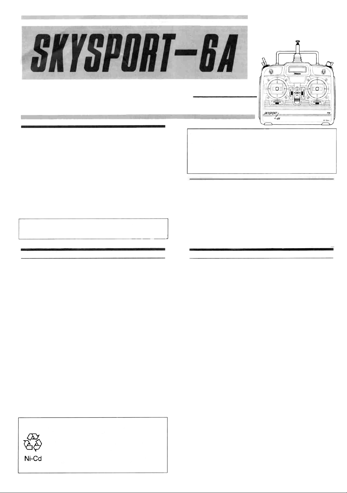
TRANSMITTER CONTROLS / OPERATION
This section describes how to operate the
transmitter. The numbers in the text correspond to the numbers in FIG.1.
For a definition of special terms, see
"GLOSSARY OF TERMS" on page 8.
Servos operation
1. |Aileron| 2. [Elevator] 3. [Throttle|
4. [Rudder]
Servos trimming
5. Aileron trim lever 6. Elevator trim lever
7. Throttle trim lever with ATL
The throttle trim affects the throttle only
when the throttle stick is in the low
range (engine is at low speed). Linkage
adjustment for the high range throttle
(engine is at high speed) is simplified
since the throttle trim only affects the
low range of the throttle movement.
8. Rudder trim lever
-2-
Page 3
Switches and knobs
9. Elevator -> flap mixing switch (ELV -> FLP)
When this switch if pulled forward, the mixing function is
turned on and the flaps are linked with elevator operation.
However, this switch is effective only when elevator -> flap
mixing is active (ACT).
10.
Flap knob (FLAP)
Normally, this knob is used as CH6. When flaperon mixing is
active (ACT), this knob acts as the flap trimmer.
11. aileron dual rate switch (AILERON D/R)
This switch toggles the aileron servo travel (RATE1 ,
RATE2). RATE1; upper position RATE2; down position
12. Elevator dual rate switch (ELEVATOR D/R)
This switch toggles the elevator servo travel (RATE1,
RATE2). RATE1; upper position RATE2; down position
13. Landing gear switch (GEAR)
This switch activates the landing gear channel. (CH5 switch)
14.
Power switch
The transmitter is turned on when this switch is set to the
upper position.
15. Trainer switch (TRAINER)
This switch is turned on when set to the pulled forward position (spring-loaded type).
Others
16. Level meter
[!] This meter indicates the transmitter power supply voltage.
When the needle deflects to the boundary between the silver
and red ranges, recharge the Nicd battery.
17.
Hook
Hook for neck strap.
18.
Antenna
[!] When using the transmitter, extend the antenna to its full
length.
19.
Carrying bar
Use this handle to carry the transmitter.
20. Battery cover
Open this cover when adjusting the trimmers on the trimmer
panel and when changing the Nicd battery.
21. Charging jack
This is the transmitter Nicd battery charging jack.
(Charging the Nicd battery)
[!] Never try to charge a dry cell battery. It will cause the battery
to overheat or explode and is very dangerous.
[!] Always charge the Nicd battery before using your R/C set.
Connect the charger's transmitter and receiver connectors to
the transmitter charging jack and
receiver servo Nicd battery as
shown in the figure(FIG.2). The
charging LEDs light to show that
the battery is being charged.
* The normal charging time is
about 15 hours. When you have
not used your R/C set for some
time, repeatedly charge and discharge the batteries two or three
times before use.
* The transmitter and receiver Nicd batteries can be charged
simultaneously or independently.
(Non-slip adjustable lever head)
The length of the lever head
of the sticks can be adjusted
as desired. Adjust the stick
length to fit your hand. (FIG.3)
1) Unlock lever heads A and B
by turning them in the directions shown by the arrows.
2) Adjust the stick to the most comfortable length and lock it by
turning head B in the directions opposite that shown by the
arrow.
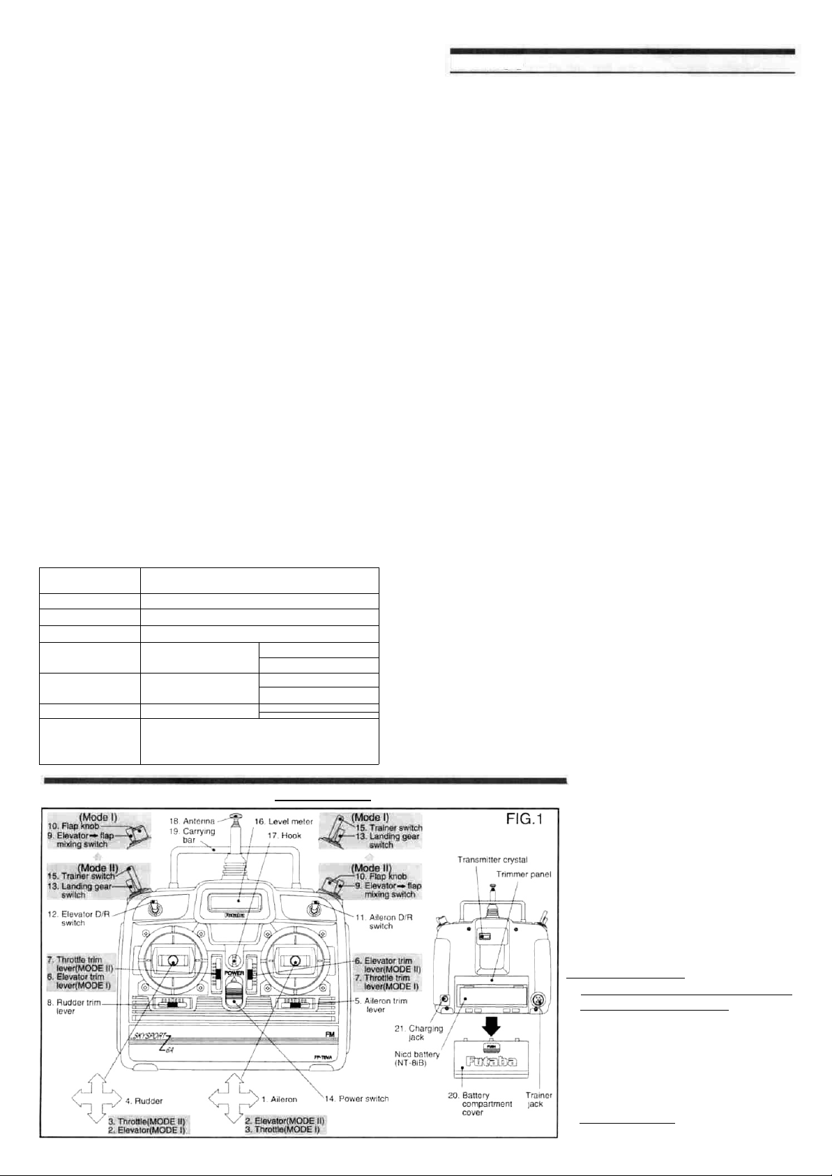
(Stick lever spring tension adjustment)
The stick lever spring
tension can be adjusted
by removing the transmitter back cover and
turning the screw for
each stick as shown in
the figure (FIG.4). Adjust
the spring tension for the
best stick feel. When adjusting the stick spring,
set the throttle stick to the
center.
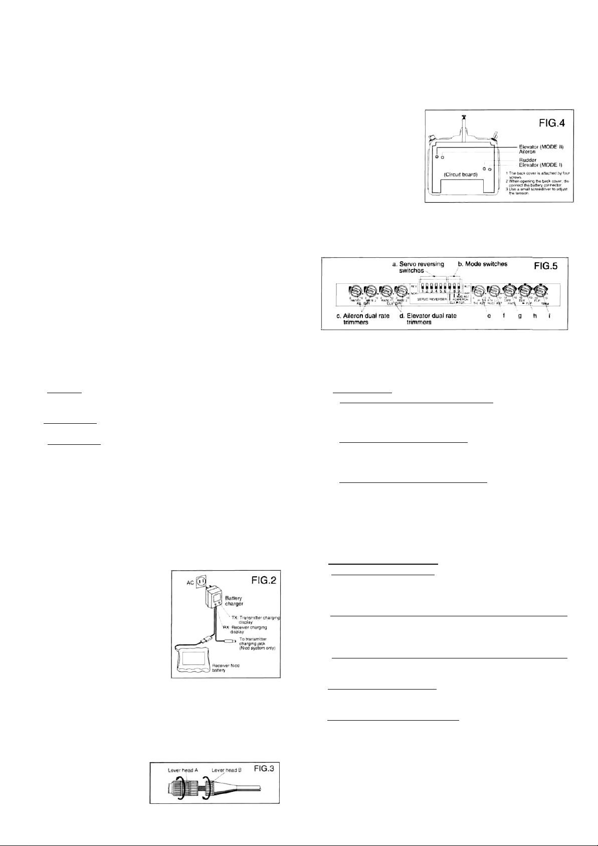
(Trimmer panel)
a. Servo reversing switch (SERVO REVERSER)
The servo reversing switches reverse the direction of travel of
the servos. The lower position is the normal position.
(Channels 1 to 6) (DIP switch Nos. 1 to 6)
b. Mode switches
1. Elevator -> flap mixing ACT/INH switch
To activate the mixing function, set this switch to the ACT
(upper) position. To deactivate the mixing function, set this
switch to the INH (lower) position. (DIP switch No. 7)
2. Flaperon mixing ACT/INH switch
To activate the mixing function, set this switch to the ACT
(upper) position. To deactivate the mixing function, set this
switch to the INH (lower) position. (DIP switch No. 8)
3. Rudder AST function ACT/INH switch
To activate the rudder and throttle AST functions, set this
switch to the ACT (upper) position. The throttle ATV function can be activated by setting this switch to the INH
(lower) position. Select the desired function.
c. Aileron dual rate trimmer (AIL D/R)
This trimmer sets the rate corresponding to both directions of
the aileron dual rate switch. (RATE1, RATE2)
When it is turned clockwise, the servo travel increases.
d. Elevator dual rate trimmer (ELV D/R)
This trimmer sets the rate corresponding to both directions
the elevator dual rate switch. (RATE 1, RATE2)
When it is turned clockwise, the servo travel increases.
e.
Throttle
(TH.ATV) H side
This trimmer adjusts the servo travel of the selected function.
When it is turned clockwise, the servo travel increases.
f. Rudder AST trimmer (RUD.AST) or Throttle ATV trimmer
(TH.ATV) L side
This trimmer adjusts the servo travel of the selected function.
When it is turned clockwise, the servo travel increases.
g. Aileron differential trimmer (DIFF.RATE)
This trimmer adjusts the aileron differential amount when the
flaperon mixing function is active.
h. EIevator -> flap mixing trimmer (ELV->FLP)
This trimmer adjusts the mixing operation direction and
amount.
i. Flap trimming function trimmer (FLP.TRIM)
This trimmer adjusts the flap trimming operation direction and
variation width when the flaperon mixing function is active.
AST
trimmer
(TH.AST) or throttle
ATV
trimmer
of
-3-
Page 4

CONNECTION OF RECEIVER, SERVOS, ETC.
bag and securing the open end of the bag with a rubber band.
Do the same with the receiver and servo battery.
Servo horns
Spare horns are supplied. Use them as needed.
Extension cord
Use the servo extension cord if needed for your particular
fuselage.
Digital Proportional Frequencies For U.S.A.
• The frequency of Futaba digital proportional sets can be
changed within their own band. There are 2 different bands
for you to choose from (27 MHz and 72-75 MHz). Please see
chart listed below for specific frequency and its intended use.
Please note there are specific frequencies allocated for air-
craft only and surface only use.
• The frequency can be changed within the same BAND. How-
ever, Futaba recommends that you return your system to our
factory service department for frequency changing, as tuning
may be necessary for proper operation. Changing frequency
from one band to another is NOT possible.
Always change frequency flag when frequency is changed.
The frequency flag is to be attached to the top of antenna and
the channel designation to the base. (See Drawing)
• It is illegal to change crystals on 72-75 MHz bands in the
U.S.A. unless performed by a licensed technician.
Antenna Frequency Flag
(Installation precautions)
When installing the receiver, servos, and other parts to the fuselage, observe the following precautions:
Servo travel
Operate each servo horn over its full travel and check that the
pushrod does not bind and or is not too loose. Unreasonable
force applied to the servo horn will adversely affect the servo
and drain the battery pack very quickly. Make sure that the
free travel range of each control surface or mechanism
somewhat larger than the full control travel (including trim) of
the servo horn. Adjust the servo horns so that they move
smoothly even when the trim lever and stick are operated simultaneously in the same direction.
Servo installation
Install the servos with the rubber
grommets and eyelets supplied with
the set. (FIG.8) Do not tighten the
screws too tight. If the servo case directly contacts the fuselage, the rub-
ber bushing will not serve its pur-pose.
Receiver power switch installation
When installing the switch harness to the fuselage, cut a rectangular hole slightly larger than the full travel of the switch in
the fuselage and install the switch so that it moves smoothly
from ON to OFF. Also install the switch where it will not be
exposed to engine oil or dust and dirt. Generally, install the
receiver switch on the opposite side of the muffler exhaust.
Receiver antenna
Although the receiver
antenna may appear to
be too long, do not cut it
or fold it back. Changing the length of the receiver antenna will
lower the receiving sensitivity and shorten the
flight range. Generally,
the antenna can be strung out towards and attached to the
vertical stabilizer. (FIG.9)
Receiver vibration and water proofing
The receiver contains precision electronic parts. Besides being susceptible to vibration and shock, the entry of water will
also cause erroneous and dangerous results and has been
associated with crashes and other accidents. Wrap the receiver in foam rubber or take other vibration countermeasures. Also waterproof the receiver by placing it in a plastic
"Install the antenna by stretching
it slightly with a rubber band, etc.
"Use a rubber bushing so that the antenna
will not be broken by abrasion where it
comes through the fuselage and always
knot it inside the fuselage so that it will
not come out.
FIG.9
The flag can be attached to.
and removed from. the
Attach the frequency flag to the flag
holder as shown in the figure.
antenna with one touch.
1 Slick the channel No. sticker
on the flag board.
2 Attach the flag board to the
antenna as shown in the
figure
Frequency, Channel No. Flag Color For U.S.A.
26-27 MHz-Aircraft/car/boat
Color
26.995 Brown
27.045 Red
27.095 Orange
27.145 Yellow
27.195 Green
27.255 Blue
50/53 MHz-Aircraft/car/boat-Fcc Amature Licence required (2
and 3 channels not produced on these frequencies).
Channel
50.800 RCOO 53.100 Black-Brown
50.820 RC01 53.200 Black-Red
50.840 RC02 53.300 Black-Orange
50.860 RC03 53.400 Black-Yellow
50.880 RC04 53.500 Black-Green
50.900 RC05 53.600 Black-Blue
50.920 RC06 53.700 Black-Violet
50.940 RC07- 53.800 Black-Gray
50.960 RC08
50.980 RC09
No. Color
72MHz-Aircraft only
72.010 11 72.210 21 72.410 31 72.610 41 72.810 51
72.030 12 72.230 22 72.430 32 72.630 42 72.830 52
72.050 13 72.250 23 72.450 33 72.650 43 72.850 53
72.070 14 72.270 24 72.470 34 72.670 44 72.870 54
72.090 15 72.290 25 72.490 35 72.690 45 72.890 55
72.110 16 72.310 26 72.510 36 72.710 46 72.910 56
72.130 17 72.330 27 72.530 37 72.730 47 72.930 57
72.150 18 72.350 28 72.550 38 72.750 48 72.950 58
72.170 19 72.370 29 72.570 39 72.770 49 72.970 59
72.190 20 72.390 30 72.590 40 72.790 50 72.990 60
75 MHz-Car/boat only
75.410 61 75.610 71 75.810 81
75.430 62 75.630 72 75.830 82
75.450 63 75.650 73 75.850 83
75.470 64 75.670 74 75.870 84
75.490 65 75.690 75 75.890 85
75.510 66 75.710 76 75.910 86
75.530 67 75.730 77 75.930 87
75.550 68 75.750 78 75.950 88
75.570 69 75.770 79 75.970 89
-4-
75.590 70 75.790 80 75.990 90
Page 5

ADJUSTMENTS
1. General fuselage adjustments
Make the basic fuselage linkage connections and adjustments specified in the fuselage manufacturer's assembly
manual. In particular, check that the center of gravity is within
the specified range.
Also make the receiver, servo, and battery connections in accordance with "CONNECTION OF RECEIVER, SERVOS,
ETC." instructions on page 4.
[!] Be sure to read and follow all of the "(Installation precau-
tions)".
Before starting adjustment, carefully read the "Transmitter
Operation and Control Surface Movement" section below.
(Transmitter Operation and Control Surface Movement)
* Turn all nine trimmers fully clockwise (to the number 10)
with the miniature screwdriver supplied.
* Set all the switches (DIP switch No. 1 to 9) to the lower
position.
(Turn on the transmitter and receiver power switches
and make the adjustments described below.)
2) Make the basic adjustments (deflection angle) specified in
the airplane design drawings or instruction manual.
3)Check the direction of operation of each servo.
If a servo moves in the wrong direction, switch its reversing
switch. (In this way the direction of operation can be
changed without changing the linkage.)
[!] Be especially careful of the direction of operation of the ai-
leron servos.
Servo reversing switch
(Setting)
The servo reversing switches (SERVO REVERSER)
(DIP switch Nos. 1 to 6) on the trimmer panel can be set
for each channel.
The following descriptions assume that the transmitter is held
in the hands in the normal position.
a)When the aileron stick is moved to the right, the right wing
aileron is raised, the left wing aileron is lowered, and the
plane will bank to the right. When the stick is moved to the
left, the reverse maneuvers are performed.
b)When the elevator stick is pulled back. the elevator is
raised and the airplane climbs (Up operation). When the
elevator stick is pushed forward, the elevator is lowered
and the airplane dives (Down operation).
c)When the throttle stick is pulled back, the engine throttle
lever arm moves to the slow (low speed) side. When the
throttle stick is pushed forward, the engine throttle lever
arm moves to the high (high speed) side.
d)When the rudder stick is pushed to the right, the rudder is
deflected to the right and the nose of the airplane turns to
the right. When the rudder stick is pushed to the left, the
rudder is deflected to the left and the nose of the airplane
turns to the left.
The lower (NOR) position is the normal position and the
upper (REV) position is the reverse position.
4)Check the neutral adjustment and left and right (up and
down) travel of each servo.
If the neutral position has changed, or the travel is incorrect, readjust it by changing the servo horn position on the
splined shaft or by changing the hole position on the servo
horn. (Adjust the neutral position by servo horn position
when the transmitter trimmer is at the center.)
5)Check the engine throttle linkage.
The throttle is opened fully when the throttle stick is set to
the high position (pushed forward) and is closed fully when
the throttle stick is set to the maximum slow position (pulled
back).
6) The throttle or rudder servo travel can be trimmed with the
following throttle ATV or throttle AST/rudder AST function.
Select the function you want to use.
Throttle ATV functioni
(Function)
The high and low throttle servo travel can be adjusted
independently. Use this function to compensate for
throttle linkage variations. The travel rate can be adjusted from 30% to 100% of the total servo travel (each
side) as shown in the figure.
(Adjustment procedure)
1) Initial trimmer and switch setting
Before making any adjustments, open the battery cover at the
back of the transmitter and set the trimmers and DIP switches on
the trimmer panel to the initial state shown below.
(Setting)
To activate the throttle ATV function, set the rudder AST
(RUD.AST) ACT/INH switch (DIP switch No. 9) on the
trimmer panel to the INH (lower) position. (Be aware that
the rudder AST function and throttle ATV function cannot
be used simultaneously.)
* High side travel adjustment:
Adjust the high side travel with the high side trimmer (H)
-5-
Page 6

of the TH.ATV trimmers on the trimmer panel. Adjust the
high side travel to between high side trimmer positions 0
(30%) and 10(100%).
* Low side travel adjustment:
Adjust the low side travel with the low side trimmer (L) of
the TH.ATV trimmers on the trimmer panel. Adjust the
low side travel between low side trimmer positions 0
(30%) and 10(100%).
Throttle AST function
(Function)
This function sets the throttle servo travel. In this case,
the high side and low side can be adjusted simultaneously. Use this function to compensate for throttle
linkage variation. The travel rate can be adjusted from
30% to 100% of the total servo travel as shown in the
figure.
(Adjustment)
To activate the throttle AST function, set the rudder AST
(RUD.AST) ACT/INH switch (DIP switch No. 9) on the
trimmer panel to the ACT (upper) position. (The rudder
AST function can be used simultaneously, but the throttle
ATV function cannot be used simultaneously.)
* Travel adjustment:
Adjust the servo travel with the TH.AST trimmer on the
trimmer panel. Adjust the travel rate between throttle
AST
trimmer positions 0 (30%) and 10 (100%).
7)After connecting the linkages and checking the operating
directions and amounts, start the engine and adjust the
engine needle, then fly the airplane and trim the servos.
2. Aileron/elevator dual rate (D/R) function
(Function)
The maximum travel of the aileron and elevator servos can
be altered by operating their respective dual rate switch.
For instance, when the switch is in the down (RATE2) position, the deflection angle is the normal deflection angle.
When the switch is set to the upper (RATE1) position, spins,
snap rolls, and other aerobatics that require a maximum deflection angle can be performed by adjusting the deflection
angle to an angle greater than the normal deflection angle.
Since the respective rates can be adjusted by setting the
switch to the upper and down positions, the direction of the
switch can be set as desired.
Rudder AST function
(Function)
This function adjusts the rudder servo travel. In this case,
the left and right travels can be adjusted simultaneously.
Use this function in rudder linkage correction. The travel
rate can be adjusted from 30% to 100% of the total servo
deflection angle as shown in the figure.
(Adjustment)
To activate the rudder AST function, set the rudder AST
(RUD.AST) ACT/INH switch on the trimmer panel to the
ACT position. The throttle AST function can be used simultaneously, but the throttle ATV function cannot be
used simultaneously.)
* Travel adjustment:
Adjust the servo travel with the RUD.AST trimmer on the
trimmer panel. Adjust the travel to between rudder AST
trimmer positions 0 (30%) and 10 (100%).
Throttle trim lever with ATL function
(Function)
As shown in the figure, when the throttle stick is set to the
maximum slow side, the throttle trim influence is also at
it's maximum. When the throttle stick is in the high side
the throttle trim has no influence. This greatly simplifies
throttle linkage adjustment. (The high side linkage
should be set first.)
(Switch operation)
The aileron dual rate switch (AILERON D/R) is at the front top
right side of the transmitter. The upper position is RATE1 and
the down position is RATE2.
The elevator dual rate switch (ELEVATOR D/R) is at the front
top left side of the transmitter. The upper position is RATE1
and the down position is RATE2.
(Rate adjustment)
Each rate can be adjusted with the RATE1 and RATE2 trimmers
on the trimmer panel behind the battery cover at the back of the
transmitter. The rate can be adjusted from 30% (position 0) to
100% (position 10) of the maximum deflection angle.
(Setting procedure)
1) Turn on the transmitter and receiver power.
2) Switch the dual rate switch of the channel you want to the position for the rate that you want to set.
3) Set the stick to the maximum travel in either
4) Using the trimmer, adjust the servo horn to the desired angle.
(Adjust each rate by repeating steps 1 through 4.)
* When not using the dual rate function, set the RATE1
RATE2 trimmers to 100% (fully clockwise).
direction.
3. Flaperon mixing
(with aileron differential function)
and
-6-
Page 7

(Function)
This function lets you mix the flap and aileron functions by
using the same control surfaces (ailerons) and servos for
both controls. Two aileron servos are mounted in the wing.
Aileron operation is accomplished normally, i.e. left and right
ailerons moved up and down in opposite directions. Flap operation is accomplished by moving the left and right ailerons
in the same direction. (Flap operation can be performed without the need for separate flap surfaces.)
* With this function the left and right ailerons can be operated
differentially. (Aileron differential function). Roll axis can be
compensated in this way. With aileron differential the aileron
down deflection angle is typically smaller that the up angle.
* The flap control knob rate can be adjusted.
(Adjustment)
Connect the aileron servos to receiver output channels 1 and
6. Adjustment when CH1 is connected to the right wing and
CH6 is connected to the left wing is described below. (The
trimmer adjustment direction may be reversed, depending on
the servo mounting direction and linkage method.)
1)Activate mixing:
To activate flaperon mixing, set the flaperon ACT/INH
switch (DIP switch No. 8) on the trimmer panel behind the
battery cover at the back of the transmitter to the ACT (upper) position. To deactivate flaperon mixing, set the switch
to the INH (lower) position.
2)Aileron differential adjustment:
Adjust the aileron differential with the DIFF.RATE trimmer
on the trimmer panel.
First set the DIFF.RATE trimmer fully clockwise (to number
10) so that differential is not applied. When the roll axis
must be compensated after test flying, make the adjustments described below. However, the trimmer adjustment
position depends on the direction in which the deflection
angle decreases.
(left half of trimmer).
In both cases the deflection angle decreases as the knob is
turned toward position 0 (trimmer center).
4. Elevator ->
(Function)
This function is used when the aircraft has flaps or is using
the flaperon mixing function. This can be used, for example,
to deploy flaps when pulling up elevator. Cleaner loops and
other aerobatic maneuvers can be performed using this function. Adjust the mixing amount to the optimal positions for
your model.
flap mixing
* Applying differential by reducing the low side of the aileron:
Adjust between DIFF.RATE trimmer positions 0 and 10
(right half of trimmer). At position 10, differential is not applied. At position 0 (trimmer center), the reducing amount is
maximum.
* Applying differential by reducing the high side of the aileron:
Adjust to between DIFF.RATE trimmer positions 0 to -10
(left half of trimmer). At position -10, differential is not ap-
plied. At position 0 (trimmer center), the reducing amount is
maximum.
3) Flap control knob rate adjustment
Adjust the flap control knob rate with the FLP.TRIM trimmer
on the trimmer panel. The flap control knob operating direction can be set at the same time.
* Lowering the flaps by turning the flap knob clockwise (CW):
Adjust the flap control knob to between FLP.TRIM positions 0 and 10 (right half of trimmer).
* Lowering the flaps by turning the flap knob counterclockwise
(CCW):
Adjust to between FLP.TRIM trimmer positions 0 and -10
(Operation)
The elevator -> flap mixing ON/OFF switch is at the right side
of the transmitter. It is turned on when pulled forward.
(Adjustment)
1)Activate the mixing function:
To activate the elevator -> flap mixing function, set the elevator -> flap mixing ACT/INH switch (DIP switch No. 7) on
the trimmer panel to the ACT (upper) position. To deactivate the mixing function, set the ACT/INH switch to the INH
position.
2) Mixing amount adjustment:
Adjust the mixing amount with the ELV.->FLP trimmer on
the trimmer panel. The adjustment range is -100 to +100%
(positions-10 to +10). The mixing direction can be adjusted
at the same time.
* Applying mixing which lowers the flaps when the elevator is
raised:
Adjust between ELV->FLP trimmer positions 0 and 10
(right half of trimmer). At position 10, the mixing amount is
maximum and at position 0, the mixing amount becomes 0.
Adjust the mixing amount to the optimal position for your
aircraft.
* Applying mixing which raises the flaps when the elevator is
lowered:
Adjust between ELV->FLP trimmer position 0 and -10 (left
half of trimmer). At position -10, the mixing amount is maximum and at position 0, the mixing amount becomes 0. Set
the mixing amount to the optimal position for your aircraft.
-7-
Page 8

5. Using the trainer function
You can practice flying with the aid of another pilot or help
another pilot fly by connecting the SKYSPORT-6A transmitter to another SKYSPORT-6A , PCM1024Z, 7UA, or 5UA
Series with a special trainer cable (sold separately).
(Use)
The model is controlled by the instructor transmitter when the
trainer switch is OFF and is controlled by the student transmitter when trainer switch to ON.
(Usage precautions)
* Never turn on the student transmitter power switch.
* Make the student transmitter and instructor transmitter set-
tings the same.
* Make sure the modulation method of the other transmitter
is FM (PPM).
GLOSSARY OF TERMS
The abbreviations used with the SKYSPORT-6A are defined
below in alphabetical order.
ACT (activate)
Means that a function is turned on. Its opposite is INH (inhibit).
To activate a function, its ACT/INH switch is set to the ACT
position. If the switch is not in the ACT position, the function is
not activated^
AILERON/AIL.
An auxiliary airfoil at the left and right wings of an airplane to
control its rolling.
AST (Adjustable Servo travel)
This feature allows adjustment of the travel of the servo
certain channel. It is used when setting up the linkages.
ATL (Adjustable Throttle Limit)
This feature allows movement of the throttle trim lever that
operates only when the throttle stick is in the SLOW position.
It is convenient because it does not affect the HIGH side of
the throttle.
ATV (Adjustable Travel Volume)
This feature allows independent adjustment of the servo
travel in each direction. It is convenient when setting up the
linkages.
D/R (Dual Rate)
This function allows switching to one of two deflection angles
while flying. The deflection angle best for the aircraft can be
set for one switch position and spins, snap rolls, and other
aerobatics that require a maximum deflection angle can be
performed easily by setting up maximum deflection for the
other switch position.
DIFF. (aileron differential)
This feature allows application of a differential to the right
wing aileron and left wing aileron when the wing has two aileron servos. It is used to correct undesirable tendencies and to
compensate the roll axis.
ELV.->FLP. (elevator->flap mixing)
This feature applies mixing from the elevators to the flaps
when the fuselage has flaps. When mixing is applied so that
the flaps are lowered when the elevators are raised, loops
and other aerobatics can be performed cleanly. The mixing
amount should be adjusted optimally for individual aircraft.
ELEVATOR / ELV.
A horizontal airfoil for making an airplane go up or down.
FLAPERON
This is a mixing function that gives the ailerons a flap function.
It is a convenient method of mixing aileron operation and flap
operation using only two aileron servos at the wings. (Flap
operation can be performed without the need for separate
flap surfaces.)
of a
FLP. (Flap)
A movable auxiliary airfoil attached to the center of a wing to
increase the lift at slow speed when taking off and landing.
With models it can also be mixed with the elevator and used
in circular aerobatics.
FLP.TRIM (Flap trim)
This feature switches the flap servo deflection angle between
normal operating angle and trim angle. It is convenient when
mixing the flaps with other channels.
GEAR (Landing gear)
This is for airplane landing gear.
Since the landing gear is normally extended or retracted, this
channel can only be turned fully on or off. It cannot be
stopped midway.
INH (Inhibit)
Means that the function is turned off (stopped). It is the opposite of ACT (activate). When a function is not used, its ACT/
INH switch is always set to the INH position.
NOR (Normal)
Used to represent the default or normal state of a function.
For example, the servo reversing function has a normal side
and a reverse side.
RATE
In the dual rate function for example, this is the rate of servo
travel in percentage relative to the normal servo travel. The
rate is adjusted with a trimmer for each function.
REV (Reverse)
Represents the servo reversing function that lets you reverse
the normal direction of servo movement, or the setting position of a switch (reverse position). It is used when the direction of the transmitter stick and the direction of servo movement are opposite of the desired movement after the servos
are mounted in the fuselage and each airfoil and servo are
connected by pushrods, etc. The direction of movement can
be corrected without changing the linkage.
RUD (Rudder)
A hinged directional surface attached to the vertical trailing
edge of the tail of an aircraft.
TH (Throttle)
Used to controls the fuel at the intake of an engine. When it is
opened, a large amount of fuel is drawn into the engine and
the engine speed increases. When it is closed, the engine
speed slows.
TRIM
A fine adjustment device that sets the deflection angle of
each airfoil for stable flight.
(OTHERS)
Mixing
A function that allows two or more different channels to be
operated together in a linked or dependent manner.
For example, when mixing is applied from elevators to flaps,
the elevator servo and flap servo can be operated simultaneously by operation of the elevator stick.
REPAIR SERVICE
Before requesting repair, please refer to this instruction manual
again and verify your settings. If you are still experiencing
trouble, please request service as follows:
Address
Your nearest Futaba dealer.
Repair
information
Describe the trouble in as much detail as possible.
1)Symptom: Including the state of the set when the trouble
occurred.
2) Digital proportional set used: Transmitter, receiver, and
servo model numbers.
3) Fuselage: Fuselage name and mounting conditions.
4) Your name, address, and telephone number.
Warranty contents
Read the warranty card supplied with your set.
* The warranty contents differ with geographic locations.
FUTABA CORPORATION
Makuhari Techno Garden BIdg.. B6F I -3 Nakase. Mihama-ku. Chiba 261-01. Japan
Phone: (043) 296-5119 Facsimile: (043) 296-5124
FUTABA CORPORATION OF AMERICA
4 Studebaker. Irvine California 92718, U.S.A.
Phone: 714-455-9888 Telex: 23-0691227 Facsimile: 714-455-9899
-8-
 Loading...