

Page 1
Futaba
DIGITAL PROPORTIONAL
RADIO CONTROL
D60399
Thank you for purchasing a Futaba digital proportional radio control set.
Please read this manual carefully before using your set.
FEATURES OF FP-6NLK/5NLK
The FP-6NLK and FP-5NLK are 6 channel (6NLK) and 5
channel (5NLK) FM proportional radio control set with a
ergonomic case created as a result of the exhaustive pursuit
of easier operation, newly designed sticks tor smooth and
positive operation, servo reversing switch for each channel,
and other innovations based on the opinions and needs of
many RC modelers.
Please read this manual before using your new set.
TRANSMITTER FP-T6NLK/T5NLK
• Reliability substantially improved by using industrial robots
to assemble the PC board.
• Servo reversing switch for each channel. Servos are reversed
by using this switch.
• Newly designed open gimbal sticks operate smoothly and
positively.
Spring tension mechanism
ing
feel of the stick lever.
•Nonslip
• RF PC board module style system in transmitter. (Internal
only)
• Functional case, created as a result of the exhaustive pursuit
of
the palm of the hand.
•Aileron, Elevator dual rate function. (Dual rate ON, OFF)
• Easy to read square transmitter battery voltage/output level
meter.
• Excellent radiation efficiency, strong 8-stage telescoping
antenna.
• Neck strap bracket provided as standard. Operation is easier
if the transmitter is hung from your neck by using the
optional neck strap.
adjustable
length as desired.
easier
operation,
lever
has
allows adjustment of the operat-
head allows adjustment
evolved a thick
case
which
of
the stick
fits
into
FM
• Large capacitor copes with voltage changes when a battery is
used.
• Vibration-resistant pin connectors.
• Fiberglass epoxy PC board with thru-the-hole plating is vibration and shock resistant.
SERVO FP-S138
SMALL, RUGGED, HIGH NEUTRAL LOW PROFILE SERVO
• Height is 0.2 in (5.2mm) lower than existing servos of its
type.
• New indirect drive potentiometer improves vibration
shock resistance and neutral accuracy.
• Futaba low-power custom 1C provides extremely high
torque, narrow dead band, and superior tracking.
• Fiberglass reinforced PBT (polybutylene terephthalate)
injection molded servo case is mechanically strong and
invulnerable to glow fuel.
• Strong polyacetal resin ultra-precision servo gear features
smooth operation, positive neutral, and very little backlash.
• Fiberglass reinforced epoxy resin PC board with thru-the-
hole plating improves servo amp vibration and shock resistance.
•Three pin connector eliminates faulty contact and improves
reliability against vibration and
insertion prevention mechanism.
•Special grommet simplifies mounting of the servo and has
an excellent cushioning effect.
• Six special adjustable splined
• Since the output torque is 34.75oz-in (2.5kg.cm) and operating speed is 0.23sec/6CT, it can be used with almost all
models.
shock. Housing has a reverse
horns.
and
RECEIVER FP-R107N
• Compact, high performance FM 7-channel receiver with PC
board space reduced to a minimum.
•Special IF amp for radio communications improves the
effective receiving range stability.
•Narrow band ceramic filter improves rejection of adjacent
channel interference.
• Futaba original squelch circuit reduces erroneous operation
by
weak
signals
roneous operation by natural noise when no signals are being
received.
(when
passing a dead
point,
etc.)
and
er-
SET CONTENTS AND RATINGS
(Specifications are subject to change without prior notice.)
FP-5NLK
FP-T5NLK x 1
FP-R107N x 1
FP-S138x4
Transmitter
Receiver
Servo
Battery holder
Switch
Others
FP-6NLK
FP-T6NLK x 1
FP-R107N x 1
FP-S138x4
NR-4J x 1
SSW-J x 1
Charger, Frequency flag. Spare horn,
Mounting screw.
Page 2
TRANSMITTER FP-T6NLK/T5N
Operating system : 2 stick, servo reverse
Aileron, Elevator dual
switch,
Landing gear switch (5ch)
[Switch (6ch) 6NLK only
Transmitting frequency : 53, 72MHz bands
Modulation system : FM
Power requirement : 9.6V NiCd battery
(NT-8LP)
Current drain : 190mA
RECEIVER FP-R107N SERVO FP-S138
Receiving frequency : 53, 72MHz bands Control system +pulse width control
Intermediate frequency : 455kHz Operating angle One side 45° or more
Power requirement : 4.8V NiCd battery (including trim)
Current drain : 13.5mA (4.8V reception) Current drain (IDLE) 6.0V, 8mA
Dimensions : 1.38 x 2.42 x 0.8 in Output torque 34.75oz-in (2.5kg-cm)
Weight : 1.55oz (43g) Dimensions 1.59 x 0.79 x 1.38 in
Receiving range : 550 yards (500m) on the (40.5 x 20 x 35.3mm)
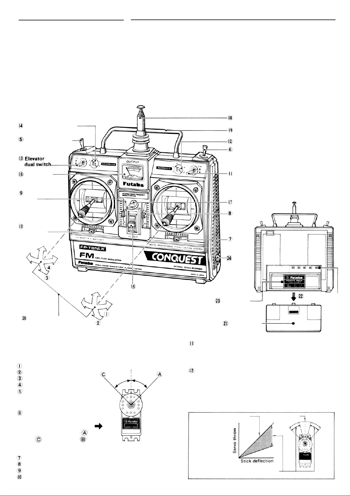
TRANSMITTER FP-T6NLK/T5N CONTROLS
Fig. 1 shows the name of each part of the transmitter.
Memorize the position and operation of each
switch and control.
Elevator dual trimmer
Landing gear switch
(Common use with servo) Power requirement 4.8V~6V
(35.2x61.7x20.3mm) Operating speed 0.23 sec/60°
ground, 1,100 yards
(1,000m) in the air.
(at the best conditions)
Weight
1.44oz(41g)
Antenna
Handle
Aileron dual trimmer
6th CH switch (6NLK only)
Level meter
Throttle trim
lever
Rudder
trim lever
Rudder
Throttle
Power switch
Nonslip adjustable
lever head
Aileron
Elevator
In the following descriptions, all the servo reversing switches
are assumed to be in the normal position. When they are in the
reverse position, operation is the opposite of that described.
Aileron
Elevator
Throttle
Rudder
Aileron operation
Elevator operation
Throttle operation
Rudder operation
®
Landing gear switch
Raising and lowering the
landing gear.
6th CH switch (6NLK only)
Use for controlling model
airplane flaps, etc. The
servo is operated at the
and positions. The
position is off.
Aileron trim lever
Elevator trim lever
Throttle trim lever
Rudder trim lever
Aileron trimmer
Elevator trimmer
Throttle trimmer
Rudder trimmer
The servo is connected
to 6 channels. Fig. 2
Aileron dual switch
Neck strap
bracket
Elevator
trim lever
Aileron
trim
lever
Charging
jack
Transmitter
Servo reversing
switches
NiCad battery
NT-8LP
Fig.1
Battery cover
Aileron dual rate switch
Aileron dual rate ON-OFF switch. When set to the upper
position, dual rate is turned on, and when set to the lower
position, dual rate is turned off.
Aileron dual rate trimmer
This trimmer sets the aileron travel when the aileron dual
rate switch is set to on. When the dual rate switch is set to
ON, the servo throw can be set to an arbitrary angle smaller than when the dual rate switch is OFF (normal) as
shown in the figure. Use the throw matched to the aircraft
and the maneuvers to be performed.
Dual rate switch
Fig.
3
When the dual rate switch is ON, the servo
throw can be adjusted within this range with the dual rate trimmer.
OFF
100%
Page 3

Elevator dual rate switch
This switch turns the
elevator dual rate function on and
off. The lower position is dual rate OFF and the upper
position is dual rate ON.
Elevator dual rate trimmer
This trimmer sets the elevator deflection angle when the
elevator dual rate switch is in the ON position. It has the
same functions as aileron dual rate.
Power switch
The upper position is ON.
Level meter
This level meter indicates the transmitter battery voltage.
Neck strap bracket
Bracket for the neck strap (optional).
Antenna
Strong telescoping antenna.
Extend
it
to
its full length
when using the transmitter.
Handle
Use this bar to carry the transmitter.
Nonslip adjustable lever head
The length of the lever head can be adjusted to fit the
operator.
Adjust to the length of your hand.
Lever head
Unlock lever heads
in the arrow direction, and adjust the head to
the most comfortable length, then lock it by
turning it in the direction opposite the arrows.
and
Battery cover
Remove this cover
when switching the
servo reversing
switches.
Remove the
battery
cover, by
pulling it in
the arrow
direction while
pressing
downward.
Fig.
5
Servo reversing switches
Using the servo reversing switches
• The left side of each switch is the normal position.
•The
servo
reversing
switches
reverse
tion of the servos.
Elevator servo
reversing switch
Aileron servo
reversing switch
Throttle servo
reversing switch
Rudder servo
reversing switch
Lever head
. by turning them
the direction
of
Fig.
4
opera-
Fig.
6
Transmitter NiCad battery NT-8LP
Charging jack
Battery charge jack for built-in NiCad battery.
•CHARGING OF
TRANSMITTER
AND RECEIVER
NI-CAD BATTERIES:
Recharge the receiver and
transmitter NiCad
as shown in Fig. 7.
batteries
AC-117V
Battery
Charger
Type
FBC-8B(4)
Tx.
LED
Rx:
Notes:
1) First, connect to TX NiCad
and red lamp goes on.
2)
Then connect to RX NiCad
after connecting, L, E, D,
changes color trom red to
greenish red (orange)
which indicates that
both TX and RX NiCads
are being charged.
3) In case of separate
charging
L, E, D, color will be:
RX NiCad - Green.
TX NiCad - Red.
Charging
plug
(NR-4J)
Fig.
7
•Connect the charging plug of the FBC-8B charge to the
transmitter charging jack, connect the 3P connector of the
FBC-8B to the receiver NiCad battery (NR-4J), and plug the
FBC-8B to a 117VAC outlet as shown in this figure.
•The
Receiver
battery
can
be
used
about 10 times at 10
minutes per flight between rechargings.
• Charge the batteries for about 15 hours. When the set is
not
in use for some time, repeat discharge and charge two
three times before use. (If the batteries
are not used for a
long time, their capacity will go down).
• FBC-8B charges transmitter and receiver NiCad batteries
independently or simultaneously.
The tension of the stick lever spring can be adjusted.
When these screws are
removed, the back cover
can be removed.
• The tension of the
spring can be adjusted
by removing the transmitter back cover and
turning the screw for
each stick. Set the
springs for the best
stick feel.
Aileron
Rudder
to
Landing
gear servo
reversing
switch.
NORM - Normal
REV - Reverse
After linkage is complete, inspect the servos. If the direction of
operation of the stick lever and the direction of operation of a
servo are opposite, switch the appropriate servo reversing switch.
Elevator
When adjusting the aileron,
and elevator the inside
module is removed.
Use a small Phillips
screwdriver.
Fig.
8
Page 4

RECEIVER FP-R107N & SERVO FP-S138
Receiver, servos, switches, and battery
connections
Extension cord
Receiver crystal
7-channel FM receiver FP-R107N
Antenna wire
Landing gear
adapter
Aileron
servo
Elevator
servo
Throttle
servo
Rudder
servo
Switch
SSW-J
Charging plug
NR-4J
PRECAUTIONS
• Connect the
shown in Fig. 9. Then extend the transmitter and receiver
antennas fully.
• Set the transmitter power switch to ON. Then set the receiver power switch to ON. The servos stop near the neutral
position. Operate the transmitter sticks and check that each
servo follows the movement of the stick.
•Connect the pushrod to each servo horn, then check if
direction of travel of each servo matches the direction
operation of
of servo travel, switch the servo reversing switch.
• Operate each servo over its full stroke, and check if the pushrod binds or is too loose. Applying unreasonable force to the
servo horn will adversely affect the servo and quickly drain
the battery. Always make the travel of each control mecha-
nism somewhat larger than the full travel (including trim) of
the servo horn. Adjust the servo horns so that they move
smoothly even when the trim lever and stick are operated
simultaneously in the same direction.
• Be alert for noise.
This set is noise-resistant, but is not completely immune to
noise. We recommend the use of noiseless parts.
receiver,
its
transmitter
servos,
switches, and
stick.
To
reverse
battery
the
firmly
direction
as
the
of
Landing gear
servo
Landing gear
servo
6th
CH
servo
(6NLK
only)
The parts enclosed by the
dotted lines must be
purchased separately.
Fig.
9
•When installing the switch harness, cut a rectangular hole
somewhat larger than the full stroke of the switch and install
the switch so that it moves smoothly from ON to OFF. This
also applies to the switch mount when the switch is installed
inside the fuselage and is turned on and off from the outside
with a piece of wire, etc. Install the switch where it will not
be exposed to engine oil, dust, etc.
SERVO MOUNTING
(Using wood screws)
(Using plywood, FRP, or
aluminum sheet)
Wood screw
with flat
Fig.
10
washer
Rubber
bushing
Grommet
Flat washer
Rubber
bushing
Grommet
Plywood,
FRP board,
Aluminum
sheet
Page 5

• Even though the receiver antenna is long, do not cut or
bundle it.
• Install the servos securely. Tighten the mounting screws
until the rubber grommet is crushed slightly. If the screws
are too tight, the cushioning effect will be adversely affected.
• Wrap the receiver in sponge rubber. Waterproof and dustproof the receiver by placing it in a plastic bag and wrapping
a rubber band around the open end of the bag. Do the same
with the receiver/servo battery. .
• Use the rubber bands wrapped around the receiver to hold
the servo and switch leads.
• After mounting is complete, recheck each part, then check
the range by making the transmitter antenna as short as
possible, extending the receiver antenna fully, and operating
the set from a distance of 20m to 30m. The movement of
each
servo
should
follow
the
movement
of
each stick
of
the
transmitter.
• After mounting and checking are complete, take your model
to the shop where you purchased the set, or to an experienced radio control modeler, and ask them to teach you how to
handle your radio control set in the proper manner and to
inspect your set-up carefully.
•To enjoy radio control models fully, be sure to observe all
safety standards.
AILERON AND ELEVATOR DUAL (dual rate ON,
OFF) ADJUSTMENT
When the dual switch is set to ON, the servo throw is made
smaller by the amount shown by the hatched lines in Fig. 10.
The servo throw can be set from 40% to 100% of the total
travel by adjusting the trimmer next to the switch with a flat
bladed screwdriver. When the dual rate switch is set to OFF,
the
throw
is
normal. When
spins, etc., set the dual rate switch to OFF and adjust the
throw mechanically by horn and rod adjustment. Set the
dual
rate
switch
to on for
for the required amount of throw.
When the dual rate switch is set to OFF, dual rate is set and
the throw becomes large.
desiring a larger
level
flight and adjust the
throw,
such
trimmer
as
for
This horn permits shifting of the
servo neutral position at the servo
horn. Setting and shifting the
neutral position
a) Angle divisions
Fig.
12
1) The splined horn has 25 segments. The amount of change per
segment is; 360: 25=14.4°
2) The minimum adjustable angle
is determined by the number of
arms or number of the holes. For
four arms, the minimum adjustable
angle is:
b) Effect
To shift the holes center line to
the right (clockwise) relative to
baseline A, shift arm 2 to the position of arm 1 and set it to the
position closest to baseline A.
(Example] For a four arm horn,
the angular shift per segment
14.4°. The shift to the right is
-
(14.4
x6) - 3.6°
To shift by the same angle in the
opposite direction, use the opposite arm number.
USING THE ANTENNA FREQUENCY FLAG
Baseline A
Fig. 13
90°
For a six arm horn, turn the arm
counterclockwise and set arm 2
to the position of arm 1. The adjustable angle is 60° - (14.4 x 4)
=2.4°.
The following splined horns are optional.
is
HORN A HORN B HORN C HORN D BORN B HORN P
Fig.
14
Fig.
11
Arm 3 shift 4.8° to the right, arm
6 shifts 2.4° to the left,and arm 4
shifts 7.2° to the right and left.
Fig.
15
Fig.
16
Insert the frequency flag into
the flag holder as shown here.
The flag can be attached to, and removed
from, the end of the transmitter antenna
with one touch.
Fig. 17
Page 6

No.
Upper case
1
Middle case
2
Bottom
3
Metal bearing
4
Potentiometer
5
6
VR drive plate
Motor
7
Motor pinion
8
VR set screw
9
1st gear
10
11
2nd gear
3rd gear
12
13
Final gear
14
Intermediate shaft
15
2-stage shaft
Servo horn 0
16
Horn set screw 2.6x8
17
Printed wiring board .... S138
18
19
S138. . . .3PB-WRB300
Lead wire packing
20
Case set screw
21
Nameplate .... S138
22
Part Name
case
Part No.
S05650
S06010
S06020
S04134
i39995
S02753
S91218
S02461
J55016
S02751
S02491
S02492
S02752
S02495
S02494
S01239
J55178
AS
1305
AT2465
S90045
J50360
S60141
Fig.
To insure prompt service, please follow the instructions given below.
1. Charge the batteries for at least 18 hours prior to shipment.
2. Return the system only. Not your complete installation. Remove the servos from their
mounts and remove the foam padding from the receiver.
3. Plugs or other modifications which interfere with factory test procedures will be returned to
factory standard at your expense.
4. Carefully pack all components individually, using sufficient packing material to prevent
REPAIR
SERVICE
Australia: FUTABA SALES AUSTRALIA PTY LTD.,
Argentine: MODELISMO AERONAUTICO DEGA SRL.
Canada: UDISCO LTD., MONTREAL
Chile: HOBBY LANDIA, SANTIAGO
Denmark: FUTABA IMPORT DENMARK.
England: RIPMAX LIMITED. LONDON
Finland: NORETRON KY. HELSINKI
Greece: C. & G. MACRIYIANNIS CO., PIRAEUS
Hong Kong: RADAR CO LTD TEL: 3.680507
Italy: RADIOSISTEMI SRL, Carrara
MELBOURNE TEL: 211.4788
BUENOS AIRES TEL: 393-2299
TEL; 481 8109
TEL: 743957
COPENHAGEN TEL: 0291 0101
TEL: 01 8048272
TEL: 90 488880
TEL: 021 3604 391 • or 021 4176191
TLX: 500494 FORTIM I
FAX: 0039 585 52247
damage during shipment.
5. Include a brief but thorough explanation of all problems and service required and tape it to
the back of the transmitter. Place a label describing the function of the servo on each servo.
6. Be sure to include your full address and tel. No., zip code inside the box as well as on the
outside.
7. Include a packing list of all items being returned, and double check to make sure that all
items are packed.
8. Upon receipt of your equipment at the Futaba factory, an estimate of the cost of repair
(over $25.00 only) will be sent to you. Your equipment will then be repaired and returned
to you upon receipt of payment or C.O.D. (cash).
This factory repair service applies only to the continental U.S.A., Hawaii, and Alaska.
18
Lebanon: KHAIRALLAH MODELCRAFT. BEIRUT
New Zealand: AMALGAMATED WIRELESS
=— TEL: 58979
Norway: HARALD LYCHE CO A/S. Drammen
Singapore: SINGAPORE HOBBY SUPPLIES
South Africa: REDIPAK (PTY.) LTD.,
Spain: HOBBY & TOY INTERNATIONAL,
Sweden: RADIO CONTROL CENTER,
U.S.A.: FUTABA CORPORATION OF AMERICA,
W.Germany: ROBBE MODELLSPORT GMBH,
TEL: 326 681
(AUSTRALIA) N.Z. LTD. WELLINGTON
TEL:
(03)
83
39
70
TEL: 5330337
JOHANNESBURG TEL: 21 1511
VALENCIA TEL: (96) 357 23 93
JONKOPING TEL: 036 145360
CALIFORNIA TEL; 2135379610
GREBENHAIN TEL: 06644 870
 Loading...