

Fusion FBUS Series, FBUL Series, FBUS NP3.2-12, FBUS NP7-12, FBUS NP12-12 Installation & Commissioning Manual
...Page 1

Combined Conventional / Analogue Addressable
Fire Alarm Control Panel
Installation & Commissioning Manual
Software version 1.14 and above
Approved Document UI-FBU-01 Issue 3.0 January 2013
Page 2

Page 3

NOTE
PLEASE READ THIS MANUAL BEFORE
HANDLING THE EQUIPMENT AND OBSERVE
ALL ADVICE GIVEN IN IT.
THIS PARTICULARLY APPLIES TO THE
PRECAUTIONS NECESSARY TO AVOID E.S.D.
The panel is safe to operate provided it has been installed in compliance with the manufacturer’s instructions and
used in accordance with this manual.
Hazardous voltages are present inside the panel—DO NOT open it unless you are qualified and authorised to do
so. There is no need to open the panel’s enclosure except to carry out commissioning, maintenance and remedial
work. This work must only be carried out by competent service personnel who are fully conversant with the contents of the panel’s separate installation manual and have the necessary skills for maintaining this equipment.
This fire alarm system requires periodic checks as specified in BS 5839 Part 1 It is the responsibility of the system
user to ensure it is regularly serviced and maintained in good working order.
Disclaimer
No responsibility can be accepted by the manufacturer or distributors of this fire alarm panel for any misinterpretation of an instruction or guidance note or for the compliance of the system as a whole. The manufacturer’s policy
is one of continuous improvement and we reserve the right to make changes to product specifications at our discretion and without prior notice. E & O E.
IMPORTANT SAFETY NOTES
!
Page 4

CONTENTS
Page
Introduction 6
Product Overview 8
Installation 9
Safety 9
General 9
Mounting the cabinet and ESD Precaution 10
Cable types and Mains Wiring 11
Fixing the cabinet 13
Mains connections 15
Control Panel 16
Panel controls 16
Panel indicators 18
Keypad 19
LCD display 20
Fusion System Components 21
Main PCB 22
Terminal block 1 22
Terminal block 2 23
Terminal block 3 24
Terminal block 4 25
DIL switch 26
Loop PCB 27
Radial PCB 28
Loop Power PCB 29
Zone LED Expansion PCB 30
Zone LED breakout PCB 31
Power Supply Module 32
Hardware configuration 35
Panel Setup & Initialisation 36
Installing additional loop or radial cards 38
Maintenance 39
Commissioning 40
General 40
Radial circuit options 41
Investigation delays 42
Radial circuit fault thresholds 44
Radial circuit connection schematic 45
Fusion Installation & Commissioning Manual Approved document No UI-FBU-01 issue 3.0
4
Page 5

CONTENTS
Page
Commissioning
Analogue addressable field devices 46
Loop wiring 48
Powering the panel 49
Connecting the battery 50
Sounder circuits 51
Remote relay contacts 51
Remote outputs & inputs 52
Remote power supply 53
Networking 54
Setting up network 54
Network diagnostics 54
System Operation 55
Fire alarm 55
Silencing / re-sounding / resetting the alarm 56
Evacuate 57
Fault conditions 58
Menu and Control Functions 60
Access levels and engineering options 61
Configuration 69
Zones 69
Device configuration 70
Device types 71
Text message 74
Set device options 74
Default device sensitivity 74
Set polling indicator 74
Ancillary base settings 74
Group assignments 75
Set programmable relays 75
Set default sounder responses 76
Set responses to remote panels 76
Set panel parameters 77
PC Configuration 78
Firmware Flash Upgrade 82
Technical Specification 84
Fusion Installation & Commissioning Manual Approved document No UI-FBU-01 issue 3.0
5
Page 6

INTRODUCTION
The Fusion combines a powerful multi-loop analogue addressable control panel with conventional
and TWIN WIRE technologies and has been designed in accordance with European standards EN54
-2 and EN54-4, Fire Detection and Alarm systems - Control and Indicating Equipment. It utilises the
latest surface mount technology with a flash programmable 32 bit micro-controller for easier software
updates.
The panel operates with Apollo, XP95 & Discovery analogue addressable protocols and also
supports the Apollo and Hochiki ranges of conventional field devices. Four internal sounder circuits
are provided in the base unit, with an additional two circuits per loop card. Extra sounder circuits can
be provided with the use of modular PCBs.
The control panel is programmable via the keypad controls or via a PC or laptop, allowing the
configuration to be created off-site and uploaded.
In addition to the requirements of EN54-2 the control panel has the following facilities:Test Condition, to allow the automatic resetting of zones in alarm for testing purposes. EN54-2
Section 10, option with requirements.
Outputs to Fire Alarm Devices, to enable an audible warning to be sounded throughout a premises
upon the detection of a fire condition or the operation of a manual call point. EN54-2 section 7.8,
option with requirements.
Output to Fire Alarm Routing Equipment, monitored signal for use with remote, manned stations
etc. EN54-2, section 7.9.1, option with requirements.
Delays to Outputs, programmable delays to outputs can be configured. EN54-2 section 7.11, option
with requirements.
Note: If these delays are configured, a manual call point must be installed near the panel for the
purpose of overriding the delay.
Disablements of Addressable Devices, EN54-2 section 9.5, option with requirements
Fault signals from points, EN54-2 section 8.3, option with requirements
Also in addition to the requirements of EN54-2, all control panels have voltage free relay contacts for
faults and fire These are to be used for local control and signalling.
The Fusion has individually isolatable panel contacts via the menu with an auto enablement feature
and the option to remove all disablements. The menu is comprehensive, yet easy to use, allowing
electrical isolation of the loop via the keyboard. The menu also includes an enhanced test mode, with
or without sounders allowing all zones to be tested simultaneously if required.
clock, with back up, utilising a smart cap rather than a battery, thus eliminating battery life issues.
The Fusion incorporates a very fast auto learn sequence, only learning selected parts of the loop,
and if required can unlearn devices from the system. It supports the Apollo ancillary base sounders
and relays, local, zonal or common operation. A device monitoring mode allows activation of the
device outputs and control of the loop polling direction. Also there is a selectable maintenance
scanning threshold.
The Fusion has full networking capabilities as standard, utilising reliable CAN bus technology, with
response settings to evacuate,1st alarm, 2nd alarm, precinct and fault signals, with programmable
responses for loop sounders, panel sounder circuits, remote relays and loop modules.
It has a real time
Fusion Installation & Commissioning Manual Approved document No UI-FBU-01 issue 3.0
6
Page 7

INTRODUCTION (continued)
It is assumed that users of this manual are competent fire alarm engineers with experience of fire
alarm installation and the relevant standards. It is recommended that the manual is read and
understood before attempting to commission or configure the control panel. The system should be
thoroughly tested following commissioning and prior to handover to confirm that it operates in
accordance with the specification and applicable legislation.
ITEMS SUPPLIED WITH THIS CONTROL PANEL
A) Fusion Quick Start Guide
Approved document No - UI-FBU-03
B) CD Containing Programming Software and pdf versions of the full Installation & Commissioning
manual (UI-FBU-01) and the full Operating manual (UI-FBU-02)
C) 2 off KEY801 Door lock keys
D) 2 off KEY107 Activate control keys
E) Spares pack containing:-
Small Cabinet Version
2 x 4K7, 0.25W EOL resistor
2 of each of the following fuses:
FNANO-0.5 - 500mA NANO Fuse (radials and sounder circuits)
FNANO-1.0 - 1A NANO Fuse (aux relay contacts, fault relay & relay 1 & 2)
FAS2.5A - 2.5A TIME DELAY. 20mm glass (loop supply)
FAS3.15A - 3.15A TIME DELAY, 20mm glass (PSU input)
FQ5A - 5A FAST BLOW, 20mm glass (battery)
Large Cabinet Version
2 x 4K7, 0.25W EOL resistor
2 of each of the following fuses:
FNANO-0.5 - 500mA NANO Fuse (radials and sounder circuits)
FNANO-1.0 - 1A NANO Fuse (aux relay contacts, fault relay & relay 1 & 2)
FAS2.5A - 2.5A TIME DELAY. 20mm glass (loop supply)
FAS5A - 5A TIME DELAY, 20mm glass (PSU input)
FAUTO7.5A - 7.5A, 32V FAST BLOW AUTO, (battery)
Note:- For continual protection against risk of fire replace fuses only with same type and rating of fuse.
Fusion Installation & Commissioning Manual Approved document No UI-FBU-01 issue 3.0
7
Page 8

PRODUCT OVERVIEW
The control panel is combined multi loop, up to 64 zone, analogue addressable and / or conventional
unit with integral power supply and space for standby batteries. It has two additional sounder circuits
per loop card as well as, auxiliary volt free contacts and various remote inputs and outputs. Also 150
soft groups are provided for cause and effects configuration, per loop or 100 per conventional radial
card.
The control panel comprises a sheet steel enclosure suitable for wall mounting with a hinged,
lockable front access door. It can be semi-recessed if required by using a suitable flushing bezel.
Cable entry is via the top or rear of the cabinet, where 20mm 'knockouts' are provided.
Different key types are used for the door lock and the ‘enable' key-switch, to control levels of access.
A 2 x 40 character, backlit LCD is fitted to display event information and function or configuration
menus. Alarm and status information is provided by LED indicators and there is a 12 button keypad
which controls the system and allows access to the function and configuration options.
The control panel has 4 conventional Radial circuits supplied as standard and can accommodate
additional 4 way conventional circuit cards up to 64 circuits. Each radial circuit is configurable in one
of 3 possible ways. The default is for a traditional conventional monitored fire detection circuit. The
circuit can be set as a ‘TWIN’ wire where detectors and sounders can be connected to the same pair
of wires. In this configuration special ‘TWIN’ wire detector bases must be used for detector r emoval
monitoring. The Third possible configuration is as a monitored sounder circuit to activate Fire alarm
sounder devices. Each circuit is assigned to a detection ‘ZONE’ by default dependant on the card
address. The ZONE number can be reassigned. Each Radial can have a 40 character location
message. The radial circuits integrate seamlessly with the analogue addressable devices and
programmed zones. The Radial circuits can be used as inputs or outputs to any cause and effect
groups on the panel.
The Fusion panel is provided with an internal power supply module. The smaller FBUS models have
a 3 Amp module and the FBUL versions have a 5 Amp module. These modules Comply with the
requirements of EN54-4 :1988 and provide temperature compensated battery management, charging
and earth fault monitoring. The power supply modules consist of an assembly comprising AC mains
to 36vdc power pack and a control PCB with heat-sink which provides the control and monitoring
functions and 28vdc nominal power output. The power supply modules have two independent current
limited outputs for supplying power to the panel circuits.
Both power supply units are designed for use with VLRA sealed lead acid type batteries see
Installation manual for details of battery models and sizes. These rechargeable batteries provide
power in the case of a loss of AC mains power.
It is possible to power the panel from a remote power supply if required and input terminals are
provided to facilitate the remote supply input and also to monitor the unit for mains and battery
failure. An integral 5 amp power supply and expansion box to allow space for 17Ah batteries is also
available.
Access to the panel functions and configuration options is at different levels enabling restricted
access to certain functions. At the user level it is possible to disable parts of the system, set the time
and date, put the system into walktest mode and view the system status. Advanced options include
configuration, maintenance checks and fault finding mode.
The control panel incorporates an 'auto-learn' feature which enables the system devices to be
recognised on initial power up. Configuration of the system operation can be achieved via the panel
controls or by downloading data created in a PC software program.
Fusion Installation & Commissioning Manual Approved document No UI-FBU-01 issue 3.0
8
Page 9

INSTALLATION
Safety
Suppliers of articles for use at work are required under section 6 of the Health and Safety at Work
Act 1974 to ensure as reasonably as is practical that the article will be safe and without risk to
health when properly used. An article is not regarded as properly used if it is used "without regard
to any relevant information or advice" relating to its use made available by the supplier.
It is assumed that the system, of which this control panel is a part, has been designed by a
competent fire alarm system designer in accordance with BS 5839 Part 1 and with regard to BS
EN 54 parts 2 and 4 in the case of control equipment and power supplies. Design drawings
should be provided to clearly show the position of any field devices and ancillary equipment.
This product should be installed, commissioned and maintained by, or under the supervision of,
competent persons according to good engineering practice a nd,
(i) BS 7671 (IEE wiring regulations for electrical installations)
(ii) Codes of Practice
(iii) Statutory requirements
(iv) Any instructions spe cifically advised by the manufacturer
According to the provisions of the Act you are therefore requested to take such steps as are
necessary to ensure that any appropriate information about this product is made available by you
to anyone concerned with its use.
This equipment is designed to be operated from 230V AC, +10%, -15%, 1A 50/60 Hz mains
supplies and is of Class I construction. As such it must be connected to a protective earthing
conductor in the fixed wiring of the installation. Failure to ensure that all conductive accessible
parts of this equipment are adequately bonded to the protective earth will render the equipment
unsafe.
General
The control panel is a micro-processor controlled, analogue addressable fire alarm control
system, comprising of one circuit board, plus add on modular circuit boards.
The enclosure consists of back box and hinged, removable lid. Constructed of 1.2mm (18swg)
zintec mild steel and powder coated in textured light grey. The enclosure is designed to give
protection to IP30 level.
These panels are designed to comply with the requirements of EN 54 part 2 , but include integral
facilities to enable connection to older systems, which may not comply with current standards.
Installation of the panel should only be carried out by qualified personnel. The electronic
components within the panel can be damaged by static charge. Suitable precautions must be
taken when handling circuit boards. Never insert or remove boards or components, or connect
cables, with the mains power on or batteries connected.
Fusion Installation & Commissioning Manual Approved document No UI-FBU-01 issue 3.0
9
Page 10

INSTALLATION (Continued)
Mounting the cabinet
The installation of fire detection and alarm systems should be carried out in accordance with
current IEE wiring regulations and in line with BS 5839 British Standard codes of practice for fire
alarm installations. The installation should be carried out by suitably qualified and experienced
technicians.
Care should be taken with regards to avoiding the close proximity of high voltage cables or areas
likely to induce electrical interference. Earth links should be maintained on all system cables and
grounded in the control panel.
Any junction boxes used should be clearly labelled FIRE ALARM.
Any ancillary devices, e.g. door retaining magnets, must be powered from a separate power
source.
Any coils or solenoids used in the system must be suppressed, to avoid damage to the control
equipment.
The site chosen for the location of the panel should be clean and dry, and not subject to shock or
vibration.Damp or salt air or environments where water ingress or extremes of temperature may
affect the panel must be avoided. The temperature should be in the range -5° to +40°C, and the
relative humidity should not exceed 95%.
ESD precaution
Electronic components are vulnerable to damage by Electrostatic Discharges (ESD). An ESD
wrist strap, suitably grounded, should be worn at all times when handling pcbs. These wrist straps
are designed to prevent the build up of static charges, not only within a persons body, but on
many other materials.
ESD damage is not always evident immediately, faults can manifest themselves at anytime in the
future.
All pcbs should be stored in static shielded bags (silvered) for safe keeping, when not mounted in
the control panel.
Fusion Installation & Commissioning Manual Approved document No UI-FBU-01 issue 3.0
10
Page 11

INSTALLATION (Continued)
Cable types and limitations
To comply with EMC (Electro Magnetic Compatibility) regulations and to reduce the risk of electrical
interference in the system wiring, we recommend the use of screened cables throughout the
installation.
Acceptable, commonly available, screened cables, which can be used on both the sounder and
detector circuits include FP200™, Firetuff™, Firecel™, MICC (Pyro™) or any other cable complying
with BS 6387 categories C, W, Z.. Refer to BS 5839 pt1 clause 26 for detailed information on cables
wiring and interconnections.
Cabling
Suitable cables should be brought into the cabinet using the knockouts provided via a suitable cable
gland recommended for use with that cable. The screen or drain wire of loop circuits should be
bonded to earth at one location only, and should be continuous throughout the circuit. Drain wires
should be terminated in the cabinet using the 4 way brass earthing terminal block p rovided.
Integrity of transmission paths
To satisfy the requirements of EN45 -2. and to ensure a reliable system, it should be designed and
maintained to local design and installation regulations.
The Fusion has loop isolators included in the panel, and external loop isolators must be included in
the loop wiring. A single short circuit fault will only disable devices in the section of wiring between
isolators. In the case of a single open circuit no devices will be lost, since monitoring will be from both
ends of the loop, a fault will be indicated in this circumstance.
A design issue with any analogue fire system is the combined effect of loop resistance, loop
capacitance and the current demand of items connected to the loop. Factors that influence this
include loop length, cable diameter, cable type, the number of isolators used and the number and
type of devices between isolators. We recommend the use of the Apollo loop calculator program
which can be used to check the integrity of a proposed installation. The following guidelines can be
used as a rule of thumb.
Maximum addressable loop length = 1km, with either 1mm2 or 1.5mm2 cables.
Maximum conventional Radial length = 500 metres, either 1mm2 or 1.5mm2 cables.
Approx 20 addressable devices between loop isolators of which no more than 6 should
be loop sounders.
Maximum 32 conventional detectors per radial circuit. Note a radial circuit must not
cover more than one physical zone area.
If loop sounders are used, use 1.5mm2 cable and do not fit more that 32 loop sounders
per loop in total.
Where conventional sounders are used, use 1.5mm2 cable and do not fit more than 22
sounders per radial circuit in total.
Fusion Installation & Commissioning Manual Approved document No UI-FBU-01 issue 3.0
11
Page 12
INSTALLATION (Continued)
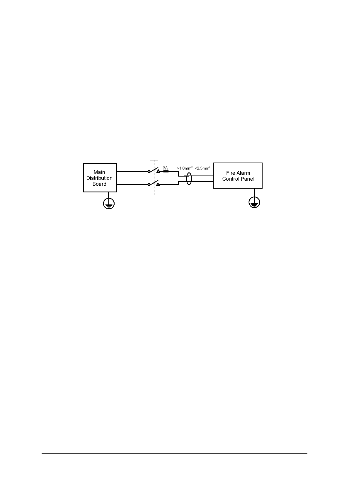
Mains wiring
The mains supply to the fire alarm panel should be hard wired, using suitable three core cable (no
less than 1.0 mm² and no more than 2.5mm² ) or a suitable three conductor system that meets the
appropriate national wiring regulations. The panel should be fed from an isolating switched fused
spur, supplied directly from the Main Distribution Board, fused at 3A. This should be secure from
unauthorised operation and be marked ‘FIRE ALARM: DO NOT SWITCH OF F’.
The mains supply must be exclusive to the fire panel.
As an alternative to a switched fused spur, an appropriately fused double pole isolating device may
be used (see diagram) providing it meets the appropriate national wiring regulations.
Recommended Batteries
The following batteries are approved for use with the Fusion control panels.
Yuasa NP range of sealed lead acid batteries or equivalent. 2 of each required for 24volt operation
FBUS small 3A version of control panel.
NP3.2-12 3.2 Ahr, 12 volt
NP7-12 7.0 Ahr, 12 volt
NP12-12 12 Ahr, 12 volt
FBUL large 5A version of control panel
NP7-12 7.0 Ahr, 12 volt
NP12-12 12 Ahr, 12 volt
NP 17-12 17 Ahr, 12 volt
The size of battery will be subject to battery standby calculations as required for BS5839
recommendations.
Fusion Installation & Commissioning Manual Approved document No UI-FBU-01 issue 3.0
12
Page 13
INSTALLATION (Continued)
Planning the cable layout in the panel
The detector and sounder circuit cabling is classed as extra low voltage and must be segregated
away from mains voltages.
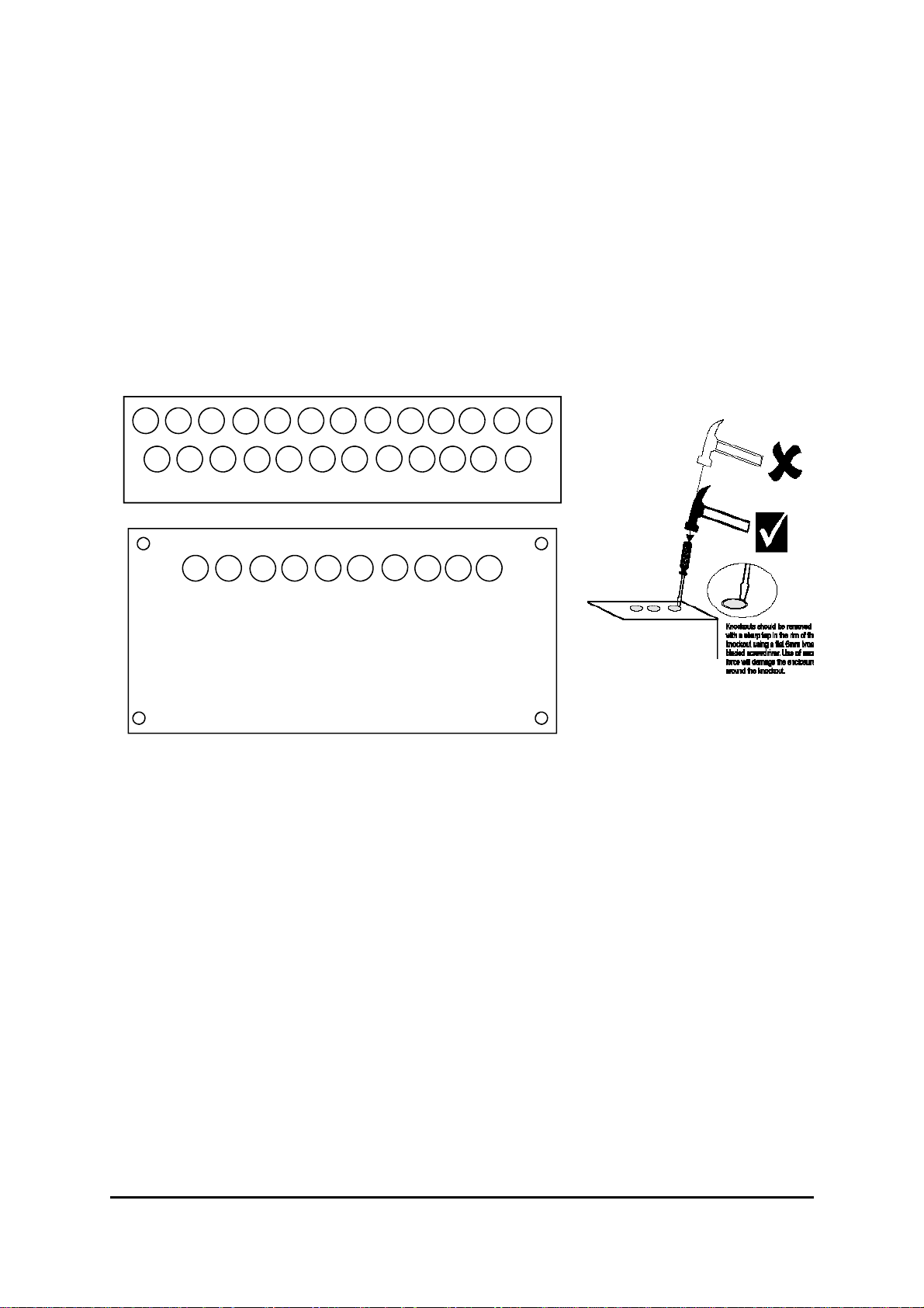
NOTE. The Main PCB should be removed before any knockouts.
Always ensure that if a knockout is removed, the hole is filled with a good quality cable gland. Any
unused knockouts must be securely blanked off.
Knockouts should be removed with
a sharp tap at the rim of the knockout using a flat 6mm broad-bladed
screwdriver. Use of excessive force
will damage the enclosure around
the knockout.
Fusion Installation & Commissioning Manual Approved document No UI-FBU-01 issue 3.0
13
Page 14
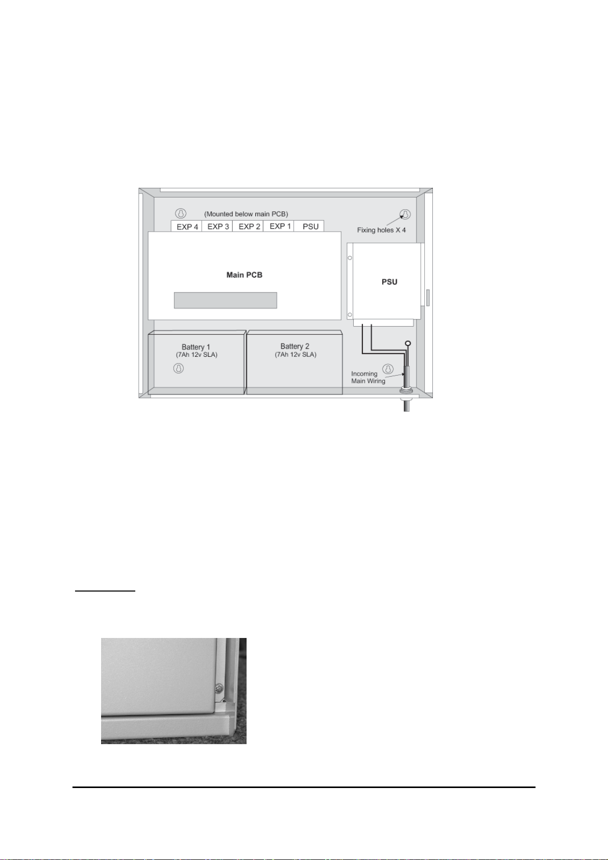
Fixing the cabinet
Secure cabinet to the wall using the four indented holes in the back box . Ensure that the box is
mounted level in a convenient location where it may be easily operated and serviced and where it is
away from possible sources of vibration or shock and ingress of moisture .
External cables should be glanded via pre-formed knockouts at the top and rear of the box as
provided.
The enclosure should be cleaned of swarf etc., prior to re-fitting of the printed circuit board.
Replace the cross head screws in the accessory PCBs and Main PCB and reconnect the cables in
TB3 & TB4. Locate the white jumper lead and connect to the batteries as per the drawing on page
31. Locate the two battery connections from the PSU board and connect to the batteries. Carefully
place the batteries as indicated in the drawing above. Ensuring that the terminals are kept well
clear of the PCB support pillars.
Important.
For the FBUL (large fusion cabinet) to maintain the integrity of Access level 3 and prevent
unauthorised access to the internal parts of the control panel. M3 torx screws must be fitted
to the locations at the bottom and top of the inner door as shown.
Fusion Installation & Commissioning Manual Approved document No UI-FBU-01 issue 3.0
14
Page 15
INSTALLATION (Continued)
Mains connections.
Do not connect the mains supply to the panel until you are fully conversant with the layout and
features of the equipment.
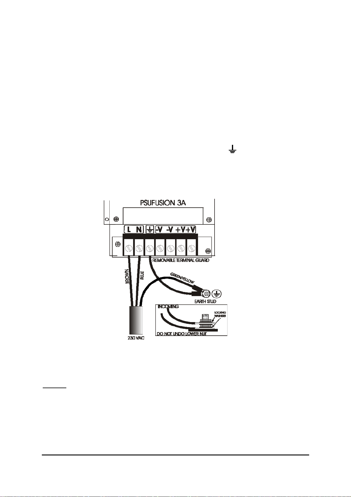
A rating plate is fitted in the bottom right hand corner of the panel describing the nature of the supply
permitted.
The incoming mains supply should be brought into the panel in the bottom right hand corner, via the
knockout provided.
A suitable cable gland must be used to secure the outer sheath of the cable used. The earth must
first be connected to the primary earth stud (peg) marked with a symbol using the ring
crimp provided.
Sufficient earth lead should be left to allow Live and Neutral connections to be accidentally pulled
from terminal block, while leaving earth connection intact. Secondary earths may be connected to
the brass earthing block.
Field devices
Sensors, call points and input/output devices are supplied with full installation instructions.
Warning
High voltage testing of the wiring must be carried out before the control panel and any devices are
connected.
Fusion Installation & Commissioning Manual Approved document No UI-FBU-01 issue 3.0
15
Page 16
CONTROL PANEL
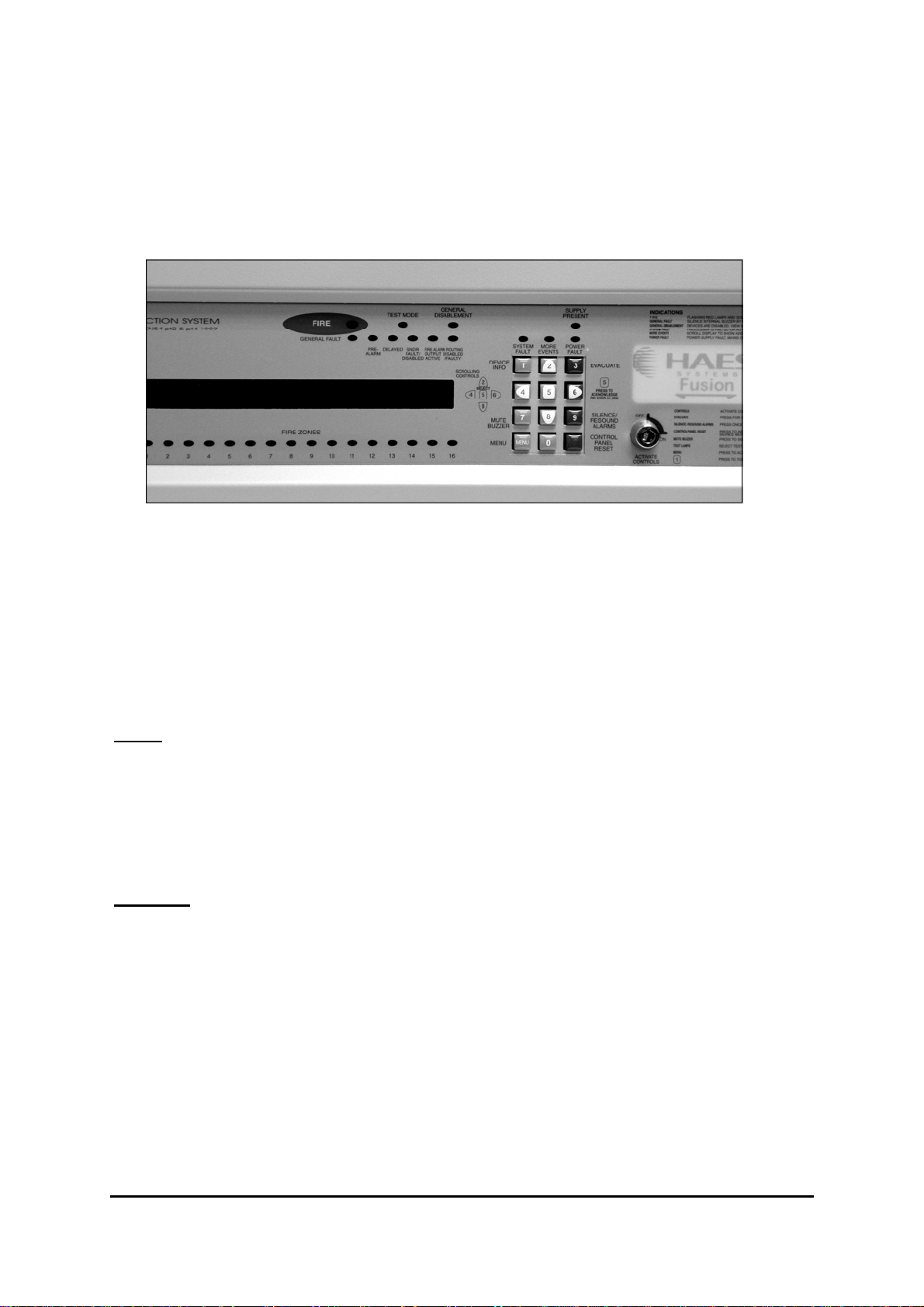
Panel Controls
Activate Controls
Controls maybe activated via key switch or 4 digit code entry. Use of the key switch precludes the
necessity to enter a code. Limited menu functions are available for viewing status information without
the need for key switch or code entry. See menu and control functions section of this manual for
further information.
If the key switch is turned to the ON position then the keypad becomes fully functional.
NOTE
Key lock
: It is not possible to withdraw the key in the ON position.
This allows authorised engineering personnel access to the inside of the control unit.
WARNING
danger. The voltages in this unit are high enough to cause injury.
Fusion Installation & Commissioning Manual Approved document No UI-FBU-01 issue 3.0
: The power to the alarm unit should be isolated before gaining access, to prevent
16
Page 17

CONTROL PANEL continued
General description
The control panel comprises a sheet-steel wall mounted enclosure with a lockable hinged door. All
the user controls and indicators are mounted on the fascia of the unit - there are no user controls
within the panel.
Normal Operation
In the normal operating mode only the green Supply Present LED (light emitting diode) should be
illuminated. The LCD (liquid crystal display) should be showing the current time, date and company
name, if programmed. Other indications that may show in normal operation are:
1. System normal – Controls are not active, limited menu available
2. Controls Active - If key-switch is in the ‘on’ position
3. Delayed – (LED) is displayed if any output delays are programmed
4. General Disablement – (LED) also shows ‘disablements active’ (LCD) displayed if any zones or
devices have been disabled, details of disablements can be viewed in ; Menu item / View active
disablements
5. Test mode – (LED) will show if engineer test mode has been set to areas on the system. Test
mode should only be used by authorised personnel.
6. Precinct Active - (LCD) remote input to activate alarm sounders is active (often referred to as
class change)
7. Alert Active - (LCD) remote input to pulse alarm sounders is active
8. Delays are Inactive - (LCD) programmed delays have been set to ‘off’.
Fire Alarm Event
A fire alarm event is caused by the activation of a field device. It may be generated automatically by
a smoke or heat detector sensing smoke or heat, or manually by the operation of a call point. In
either case it will cause an audible alarm to be given (usually throughout the building) and the event
details to be displayed and indicated on the control panel.
NOTE . Each system is individually configured for the required operation. Space is provided in the
manual to record the method of operation of this system, which should be completed by the installer.
The prescribed emergency fire alarm drill should commence immediately the alarm is heard (see
System Operation)
Fault Event
A fault event is generated when the control panel detects an internal malfunction or a fault on an
external circuit or device. A fault is indicated by the relevant LED/s and the buzzer sounding. A fault
description is shown on the LCD. Additional information about the fault may be obtained by pressing
button [ 1 ]
Control Event
A control event is caused by the operation of one or more of the keyboard pushbuttons. All controls
are inoperable until the 'Controls' keyswitch is set to the 'on' position, to prevent unauthorised
operation. A keypad is provided to silence and reset the system following a fire or fault event, initiate
an evacuation alarm, and to access the menu functions.
Fusion Installation & Commissioning Manual Approved document No UI-FBU-01 issue 3.0
17
Page 18

PANEL INDICATORS
Fire
Indicates the presence of a Fire Alarm signal or an Evacuate command. Flashes red when there is a
fire and goes steady when alarm is silenced. Subsequent alarms will re-start the flashing.
Test Mode
Indicates system is in the Engineers Test mode.
General Disablement
Indicates that part of the system is disabled (isolated)
Supply Present
Indicates that the Mains or Battery supply is present.
General Fault
Indicates that a fault is present on the system. The LCD will show the details.
Pre-Alarm
Indicates that a detector has recorded a higher than normal analogue value which could signal an
impending fire condition.
Delayed
Lit when one or more output delays have been programmed. Flashes when one or more output
delays are running.
Sndr Fault / Disabled
Indicates a fault on the alarm sounder circuit. Sounder devices / circuits may be faulty or disabled.
(Fault = flashing, Disabled = steady)
Fire alarm routing output active.
Designated output to inform monitoring service is activated.
Fire alarm routing output disabled/faulty
Designated output to inform monitoring service has been disabled or has a fault condition
System Fault
Indicates that the processor has halted. This can only be reset by manual reset at access level 2. Will
remain on even if the system has automatically re-started
More Events
Indicates that there are more events. Scroll to view them
Power Fault
Indicates power supply failures. The LCD will show the details.
Fire Detection Zones
Up to 64 indicators (Zones 1-64) to show which area (group of devices) has activated in a fire
condition. LED will flash for new zone in alarm and become steady when alarm is silenced.
Fusion Installation & Commissioning Manual Approved document No UI-FBU-01 issue 3.0
18
Page 19

KEYPAD
All the numbered keys are digits in their own right but also have the following additional functions:-
[ 1 ] Press for more information about an active device
[ 2 ] Scroll up
[ 3 ] Generate full alarm (evacuate)
Override active delay( if a delay is running)
[ 4 ] Scroll left
[ 5 ] Select to view option or Enter. Acknowledge fire alarm and start investigation delay
(if a delay is running)
[ 6 ] Scroll right
[ 7 ] Mute internal fire/fault buzzer
[ 8 ] Scroll down
[ 9 ] Toggle: silence/re-sound alarm.
[ 0 ]
[ MENU ] Access to menu
[ ] (Bottom right) Control panel reset
Fusion Installation & Commissioning Manual Approved document No UI-FBU-01 issue 3.0
19
Page 20

LCD DISPLAY
The LCD displays event information, status information, and the option menus. It has two lines of
text, each with 40 characters , and is backlit when there is an active event on the system or the
menu options are accessed. In the normal operating mode the backlight is dim and the top line
displays a default text message or user-defined text. The second line displays the current time
and date, e.g.
When an event occurs, the backlight is activated and the LCD shows the event details, e.g.
SYSTEM NORMAL 9:36 15/03/04
FIRE ZONE 01 OF 01 Z0NES 01 OF 01
PANEL 01 RECENT ZONE 01
The display shows the event type, i.e. Fire, the zone that the activated device is in, i.e. zone 1,
and the number of events, i.e. 1. The bottom line alternates with the device location text (if programmed)
Pressing button [1] reveals the device information, Type, i.e manual call point, address number
and time and date of the event. This button will function regardless of status of keyswitch.
NOTE : Fault conditions on the system are suppressed when Fire events are present. The GEN-
ERAL FAULT LED is illuminated and faults can be viewed if required via the 'View Active Faults'
option - when button [1] is pressed.
The bottom line displays a text message describing the device location.
In the menu mode, menu options are displayed as follows:
The Keypad is used to navigate through the menu options and select functions as described in
the installation and commissioning manual.
FUSION PANEL
SELECT MENU OPTION
5 — TEST LAMPS
Fusion Installation & Commissioning Manual Approved document No UI-FBU-01 issue 3.0
20
Page 21

FUSION SYSTEM COMPONENTS
The fusion control panel is made up of the following system components
Part number Description Features
TPCFSB17
TPCPSUF-3A
PSULS100-36
TPCPSUF-5A
PSULS150-36
TPCFSB10(E)
TPCFSB11
Main display /control board
2 x 40 character LCD display
12 button elastomer keypad
16 zonal fire indicators
3 Amp Power supply control PCB Battery charging up to 12Ahr
Mains to 36v DC switch mode power
pack for 3Amp power supply
5 Amp power supply control PCB Battery charging up to 17Ar bat-
Mains to 36v DC switch mode power
pack for 5Amp power supply
Expansion cards Bank mother board
supports up to 4 loop / radial cards
(E) denotes expansion board for further
banks of cards beyond 4 loops
Analogue addressable loop card
Apollo xp95 / discovery protocol
Hochiki ESP protocol
4 conventional radial circuits
4 sounder circuits , fault relay
2 configurable relays, remote
control inputs , 6 programmable
outputs
batteries, Fully monitored EN54
Universal mains input
teries , Fully monitored EN54
Universal mains input
(Note :- range switch selected)
28v power input
36v loop power
(E) version has additional 5v
supply for loop/radial cards
Single loop up to 500mA load
2 conventional sounder ccts
2 configurable relays
TPCFSB18
Conventional, TWIN or sounder ccts
TPCFSB12-64
SW-FSB25
Fusion Installation & Commissioning Manual Approved document No UI-FBU-01 issue 3.0
USB to serial download adaptor, leads
4 way radial card
Expansion zone led card 48 additional zonal fire leds
and software disk kit
4 conventional radial circuits
2 configurable relays
Std programming and download
kit
21
Page 22

MAIN PCB
Adjustments
Contrast
The display contrast should be adjusted for convenient viewing in the light available.
Volume Adjust
The Fault buzzer volume can be adjusted to suit requirements. It should be noted however that
on the minimum setting the buzzer is muted. The Fire buzzer and system fault buzzer
Volumes cannot be adjusted.
Connections
Terminal block 1.
Key switch connections. ‘KEY SW’ ‘0V’ With the key switch in the “ON” position these terminals
are shorted together. Extra 0v terminals are provided for use with inputs.
Fusion Installation & Commissioning Manual Approved document No UI-FBU-01 issue 3.0
22
Page 23

MAIN PCB(continued)
Terminal Block 2 - Radials 1 –4
Connections for four conventional circuits. Monitored 4K7 0.25w end of line resistor. Max load
500mA (Fused) 19.2 v min 28volts max.
Inputs. (connect to 0v to trigger, max input voltage 28v)
Note:- These inputs will operate at any time and are not influenced by the ’access level’ status of the
controls
A ALERT
pulsing sounders (non latching input)
E EVAVUATE
S SILENCE
R RESET
P PRECINCT
continuous sounders (latching input)
remote silence alarms input
remote reset input
(class change) sounder activation (non latching input)
CF/R
CF/LT
RS
PA
RE/M
SC/F
CAN
common fire
common fault
reset
pre-alarm output
remote output
common fire (silenced by system silence)
comms link for networking purposes
DC Outputs. (grounded when o/p. max current 100mA, Max voltage 28v)
Fusion Installation & Commissioning Manual Approved document No UI-FBU-01 issue 3.0
23
Page 24
MAIN PCB (continued)
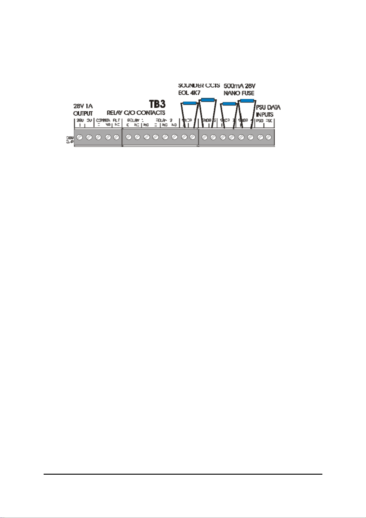
Terminal Block 3
28V 1A
COMMON FLT
C
NO
NC
RELAY 1
RELAY 2
SNDR 1 - 4
PSD
PSC
ancilliary 28v supply output, fused @ 1A, for fire alarm use only
relay o/p, volt free contacts fail safe operation
common
normally open
normally closed
configurable relay, isolated by menu, volt free, NO/NC as above
configurable relay, isolated by menu, volt free, NO/NC as above
conventional sounder circuits 28V fused 500mA
Note :- sounder circuit 4 can be reconfigured to be a remote output (output
to fire alarm routing equipment) EN54-2 option with requirements section
7.9.1
power supply data signal input
power supply clock signal input
Fusion Installation & Commissioning Manual Approved document No UI-FBU-01 issue 3.0
24
Page 25
MAIN PCB (continued)
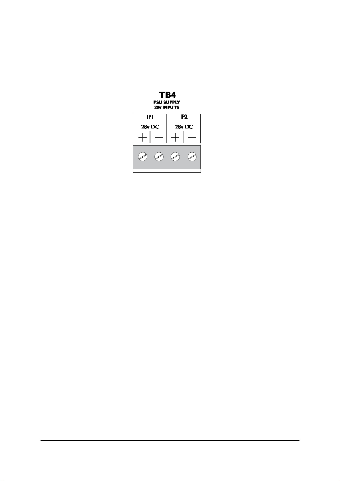
Terminal Block 4
28V DC 28 volt supply inputs from power supply to power panel. Separately short circuit pro-
tected and monitored . Maximum input capacity 5Amps
IMPORTANT! DO NOT LINK THE TWO 28V INPUTS TOGETHER
The short circuit protection will be compromised. Wire the 2 inputs separately from
the 2 outputs at the power supply. A short or open circuit on either of these input
.
channels will be reported as faults on the Panel display.
Fusion Installation & Commissioning Manual Approved document No UI-FBU-01 issue 3.0
25
Page 26

MAIN PCB(continued)
Dual in Line Switch.
Switch 1 - 4
Switch 1
Switch 2
Switch 3
Switch 4
Switch 5
Switch 6
Switch 7
NOTE:-
Each panel on the network must occupy a different panel address, including network repeater
panels.
Panel addresses may be contiguous. i.e not in numerical sequence gaps are permitted. If a network
error is present the following message is shown on the LCD display.
NETWORK ERROR
PANELS FOUND -1L34- - - -
From this display it is possible to determine the network status, The — signifies a missing panel, a
number shows address present. L signifies the address location of the currently viewed panel. This
information must be compared to the known system setup.
These four switches are used for network addressing and set the panel
number. They represent a binary value with switch 1 as the lease significant bit (LSB) and switch 4 as the most significant bit (MSB). All switches
have a 0 value when switched off.
(labelled 1 on PCB legend) = 1
(labelled 2 on PCB legend) = 2
(labelled 4 on PCB legend) = 4
(labelled 8 on PCB legend) = 8
panel address range = 00 to 15
(labelled 16 on PCB legend) not currently in use
(labelled P on PCB legend) This switch is for program mode. It enables
the engineer menu options for configuration. This switch is also a memory
write protect switch.
(labelled F on PCB legend) This switch is for use when re-programming
the processor firmware. DO NOT OPERATE THIS SWITCH IN NORMAL
USE!
Fusion Installation & Commissioning Manual Approved document No UI-FBU-01 issue 3.0
26
Page 27
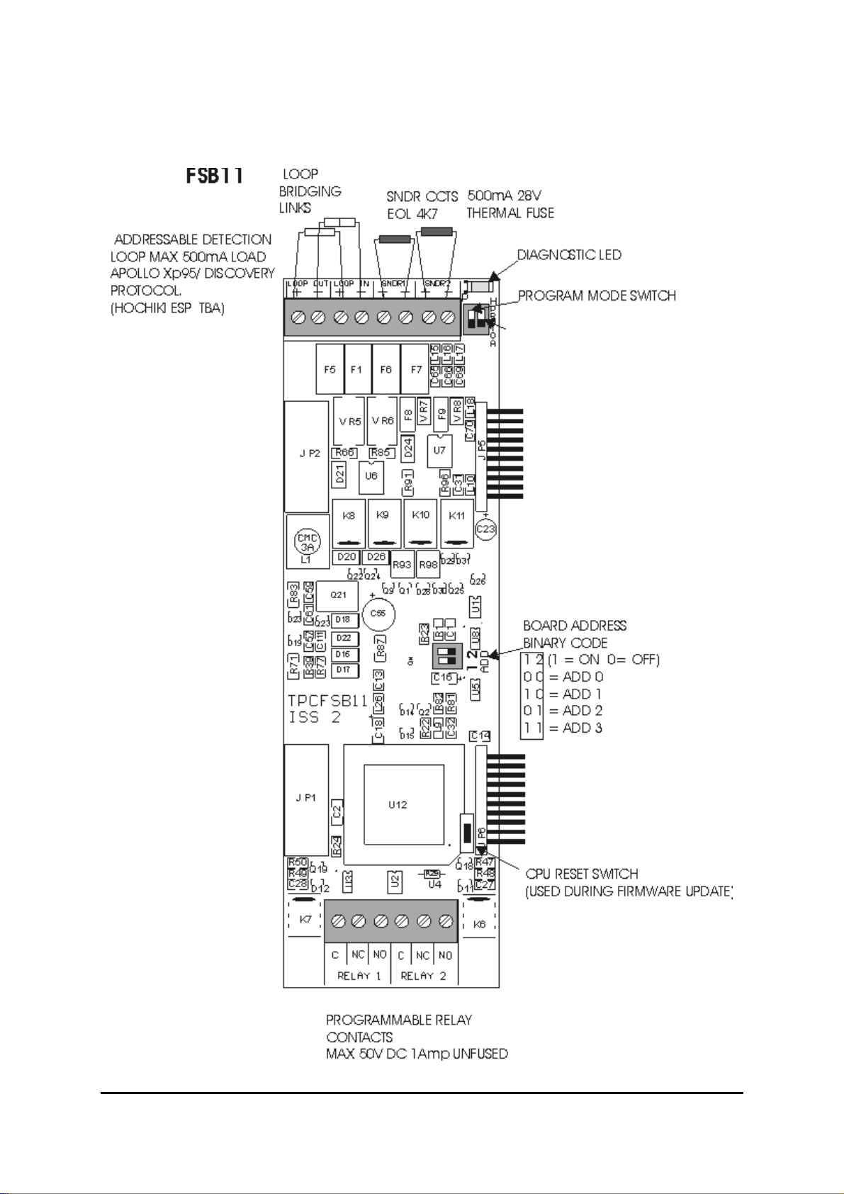
LOOP PCB
PCFSB11 Loop Card
Fusion Installation & Commissioning Manual Approved document No UI-FBU-01 issue 3.0
27
Page 28

Conventional PCB
PCFSB18 Radial Card (conventional circuits)
Fusion Installation & Commissioning Manual Approved document No UI-FBU-01 issue 3.0
28
Page 29

LOOP POWER PCB
PCFSB10
IP 1 IP 2
Fusion Installation & Commissioning Manual Approved document No UI-FBU-01 issue 3.0
29
Page 30

ZONE EXPANSION LEDs PCB
PCFSB12
Ribbon cable to PCSLA13 (red stripe to top)
Flash Firmware
upgrade switch
Fusion Installation & Commissioning Manual Approved document No UI-FBU-01 issue 3.0
30
Page 31

ZONE LED BREAKOUT BOARD
PCSLA13
Fusion Installation & Commissioning Manual Approved document No UI-FBU-01 issue 3.0
31
Page 32

POWER SUPPLY MODULE
PSUFM-3A
The Voltage output is factory adjusted to 27.6 volts ± 0.2 volts. (off load), and with the batteries disconnected. The power supply is temperature compensated in line with battery manufacturers recommendations.
For details of the battery connections see page 49.
1 12V
Ancillary 12 volt to the main PCB unit. Fused on the Main PCB
at 100mA. For use on ancillary devices.
2 PSC
3 PSD
4-5 28v DC
OP1 / OP2
6-7 BATT
Fusion Installation & Commissioning Manual Approved document No UI-FBU-01 issue 3.0
Clock output from power supply PCB to main PCB
Data output from power supply PCB to main PCB.
27.3 volt supply from PSU to power Panel. Separately protected at
full output current.
Battery charging output
32
Page 33

POWER SUPPLY MODULE
The Fusion power supply is a sophisticated fully compliant EN54-4 unit. The following indications
are provided on the power supply in addition to information given by the main control panel display
Supply On (green)
Mains Fault (amber)
Battery Fault (amber)
Battery Disconnection
Voltage Fault (amber)
Earth Fault (amber)
OP1 Limit (amber)
OP2 Limit (amber)
Indicates the presence of power at all times (battery and or mains supply)
Mains supply has been disconnected or power from 36v power pack is not
present.
The battery is not connected or the battery voltage is below 19.8vdc or the
battery has a high resistance (greater than 0.8R)
To prevent deep discharge to sealed lead acid cells. If the load current is
greater than 500mA the battery will be cut off at 19.2vdc. If the load current is
less than 500mA the battery will be cut off at 22vdc
Indicated if the charger voltage is less than 23vdc or greater than 29.2vdc
Indicated if there is a connection between the 28 volt supply rails and Earth
lower than 100K Ohms impedance
There is a short circuit or excessive load on 28v OP 1
There is a short circuit or excessive load on 28v OP 2
Testing and maintenance
Disconnect the mains supply. The ‘General Fault LED ’ and the ‘ Power Fault LED’ will show and
the internal buzzer will sound . The LCD will indicate ‘ MAINS FAIL ’.
Mute the buzzer by pressing the No. 7 key on the keypad, ‘mute buzzer’. Reconnect the mains, all
Fault LEDs will extinguish.
Disconnect the battery. After a period of time in the region of 60 to 80 seconds ,The ‘General Fault
LED ’ and the ‘ Power Fault LED’ will show and the internal buzzer will sound . The LCD will
indicate ‘ Low battery fault ’.
Mute the buzzer by pressing the No. 7 Key on the keypad, ‘mute buzzer’. Reconnect the battery,
all Fault LEDs will extinguish after a 60—80 second delay.
Calibration Mode
The Fusion Power supply has a calibration mode to enable simple checking of the battery charging
voltage setting. The Voltage setting is normally calibrated in the factory and should not require
adjustment. However local conditions may require small adjustments.
The power supply has a temperature compensation circuit so the ambient temperature will need to
be taken into account. see the attached chart detailing possible battery charging voltage Vs
temperature.
The calibration mode is entered using the calibration mode dil switch. This switch will set the PSU
into CAL mode for 60 seconds only. The normal state for the CAL mode switch is in the ‘ON’
position switching ‘OFF’ will invoke the CAL mode .During Cal mode the charger voltage should be
monitored with a voltmeter calibrated to a known NAMAS standard source. There is a small square
pad on the pcb next to the CAL switch labelled + this point is for the +Ve lead of the voltmeter and
the –ve lead of the voltmeter should be connected to 0V which can be the nearby –36v terminal.
During CAL mode all the PSU LEDs will flash together intermittently and the battery is disconnected
internally from the charger. (Note a mains fail during CAL mode will cause the panel po wer
down).The Voltage setting can be checked now. There are also two additional switches which will
cause the PSU to simulate the charging voltages for a range of temperatures . Voltages will be
checked in the area of 26—30V DC (For meter setting information.) Procedure continu es on next
page.
Fusion Installation & Commissioning Manual Approved document No UI-FBU-01 issue 3.0
33
Page 34

Float Voltage for Yua sa NP ra nge batteries
29.000
28.500
28.000
27.500
27.000
26.500
26.000
25.500
25.000
Float Voltage
24.500
-10.0 -5.0 0.0 5.0 10.0 15.0 20.0 25.0 30. 0 35. 0 40. 0 45. 0 50.0
When starting CAL mode:- Ensure CAL switch is in ‘ON’ and 1 & 2 are ‘OFF’
Set CAL switch to ‘OFF’ observe fault LEDs flashing, check voltage at test pin against chart for ambi-
ent temperature e.g. for 20 Deg C should be 27.3V +/- 0.3 volts.
If this is within limits Operate the 1 switch to ‘ON’ and check the voltage is within limits for >30 deg
C, (26.7v +/- 0.3v).
Switch ‘ON’ 2 and check the voltage within limits for <5 deg C (28.1v +/- 0.3v). Then Switch ‘OFF’ 1
& 2 and return CAL switch to ‘ON’ (normal) position.
If any voltage is outside the limits the voltage can be adjusted at the CAL mode only setting for the
correct level for the ambient voltage. Ideally the settings should be along the middle line above or at
least within the two limit lines.
CAL mode will automatically drop out after 60 seconds, recycle the CAL switch to restart.
EMON SWITCH - Electronic monitoring, selects PSU comms protocol. This is normally set to ‘on’ for
Fusion panels.
EARTH MONITORING - To disable earth fault monitoring, disconnect wire from earth monitor circuit
inputs.
NOTE:- Earth faults should be rectified urgently as further earth faults could lead to equipment damage or false alarms.
Mains to 36V DC Switch mode power supply
Ag ai nst te mper ature
Min
Nom
Max
Temperature
The PSUFUSION utilises a Switch mode power supply to convert the mains voltage to 36V DC.
The unit is factory set to 36V DC +/- 0.5V and can be checked by measuring across –V and +V
terminals. There is an adjuster potentiometer next to the terminals.
Fusion Installation & Commissioning Manual Approved document No UI-FBU-01 issue 3.0
34
Page 35

Fusion Installation & Commissioning Manual Approved document No UI-FBU-01 issue 3.0
35
Page 36

PANEL SET UP AND INITIALISATION
As delivered from the factory the control panel will be supplied completely set up and no initialisation
will be required.
The addition of expansion boards will require changes to the configuration of the panel. This will involve changes to the DIL switches and settings in the control panel parameters.
FSB17 Main Board DIL Switch Setup
123 45 6
1
2
4
8
16
P
7
F
ON
Panel Switch 1 2 3 4 5 6
1 Address 0 0 0 0 0 x x
2 Address 1 1 0 0 0 x x
3 Address 2 0 1 0 0 x x
4 Address 3 1 1 0 0 x x
5 Address 4 0 0 1 0 x x
6 Address 5 1 0 1 0 x x
7 Address 6 0 1 1 0 x x
8 - 15 Address 7 etc 1 1 1 0 x x
16 To address 15 1 1 1 1 x x
P Program mode x x x x x 1
F Flash upgrade x x x x x 0
FSB10 BANK Address DIL Switch Setup
Bank Switch 1 2
1 Address 0 0 0
ON
BANK ADD
12
2 Address 1 1 0
3 Address 2 0 1
4 Address 3 1 1
7
SWITCHES
X
1 - 4 = PANEL NETWORK ADDRESS
5 = NOT IN USE
X
6 = PROGRAM MODE (WRITE PROTECT)
X
7 = FLASH PROGRAM MODE
X
X
X
X
X
X
0
1
KEY
0 = OFF, 1 = ON, X = NOT USED
Set ‘ON’ when required
SWITCHES
1 - 2 = BOARD BANK ADDRESS
MAX 4 BANKS
N.B.
For BANK 1, the switches are no longer fitted
FSB11 Loop Card DIL Switch Setup
Board Switch 2 3
S3
ON
12
1 Address 0 0 0
1 2
ADD
2 Address 1 1 0
3 Address 2 0 1
4 Address 3 1 1
Fusion Installation & Commissioning Manual Approved document No UI-FBU-01 issue 3.0
S3 BOARD ADDRESS SWITCH
1 & 2 BOARD ADDRESS MAX 4 BOARDS PER BANK
IMPORTANT
BANK/BOARD ADDRESS WILL SET LOOP/ZONE No
SEQUENCE BY ADDRESS ORDER
36
Page 37

PANEL SET UP AND INITIALISA TION
FSB18 Radial Card DIL Switch Setup
ON
12 3
P12
Switch 1 2 3
Address 0 x 0 0
Address 1 x 1 0
Address 2 x 0 1
Address 3 x 1 1
SWITCHES
1 = NOT USED
2 & 3 = BOARD ADDRESS. MAX 4 BOARDS PER BANK
Fusion Installation & Commissioning Manual Approved document No UI-FBU-01 issue 3.0
37
Page 38

INST ALLING ADDITIONAL LOOP OR RADIAL CARDS
Switch off all power to
panel
Switch on program mode
DIL switch on main proc-
essor PCB (TPCFSB17)
[MENU]
[ 8 ]
Scroll to option 7
‘SET NUMBER OF BOARDS’
[ 5 ]
[ 2 ]
Fit card into spare slot
and secure with screws
Turn ‘Activate Controls’
key-switch on
Scroll to option 12
‘ENTER ACCESS LEVEL 3’
[ 8 ]
Increment to new number
of boards
[ 5 ]
[ 5 ]
Set board address using
DIL switch
Switch on power to panel
Enter engineers code
1 - 9 - 5 - 0
[ 8 ]
Scroll to option 4
‘SET PANEL PARAMETERS’
[MENU]
Scroll to option 9
‘INITIALISE BOARD PARAMETERS’
[ 8 ]
[ 5 ]
Scroll to added boards.
Press [5] to select
[ 5 ]
CAUTION
Select correct board. Any
programming will be cleared!
Wait for confirmation of
initialisation
[MENU]
Fusion Installation & Commissioning Manual Approved document No UI-FBU-01 issue 3.0
Press MENU several times to
exit completely.
38
Page 39

MAINTENANCE.
Periodic system maintenance should be carried out in line with the local design, maintena nce and
installation regulations.
The standby batteries should be checked for physical condition to include checking integrity of
the connections and battery cables, The batteries should be load tested to ensure they have adequate capacity. Any sign of venting or case warping should be dealt with by replacement and
careful checking of charging voltages etc.
The panel should require no other regular maintenance other than cleaning with a soft cloth and a
light application of a non abrasive cleaning agent (soapy water) to clean the fascia. Do not use
strong solvents to clean the panel.
The event logs should be inspected and any recurring faults should be investigat ed.
Fusion Installation & Commissioning Manual Approved document No UI-FBU-01 issue 3.0
39
Page 40

COMMISSIONING
General
When the control panel is installed and the wiring is complete, the system can be
commissioned. The commissioning procedure compri ses two main elements:-
(i) connecting the external wiring circuits and powering the panel.
(ii) configuring the system for the required operation.
Conventional Field devices
The control panel operates with the Apollo series 65 Conventional devices, Hochiki CDX range
conventional and accepts a wide range of Conventional field devices of other manufacture.
Field devices should be connected to the radial circuits in accordance with the manufacturers
instructions supplied with them, ensuring that where necessary a 24V DC supply is available,
and monitoring resistors are fitted. The following chart is a brief overview of the supported devices and relevant part numbers. Please consult with Technical support for details of unlisted
devices.
Device Part no.
Apollo series 65 Ionisation smoke detector 55000-217
Apollo series 65 optical smoke detector 55000-317
Apollo series 65 A1R combined heat detector 57 deg C 55000-122
Apollo series 65 detector base with diode 45681-201
Apollo series 65 TWIN wire detector base 45681-206
Hochiki CDX Optical smoke detector SLR-E3N
Hochiki CDX combined heat detector 60 deg C DCD-AE3
Hochiki CDX fixed heat detector 60 deg C DFJ-AE3
Hochiki CDX detector base with diode YBN-R-6SK
Hochiki CDX TWIN wire detector base YBO-R-6PA
Haes Systems remote indicator led for smoke detectors RIL58
KAC Indoor call point with 470 OHM resistor MCP1A-R-470
KAC indoor call point with 220 OHM resistor (priority alarm) MCP1A-R-220
KAC indoor call point for use with TWIN wire MCP1B-R-TW
Fulleon Squashni base mounted sounder SQ-03-W
Fulleon Roshni wall mounted sounder ROLP-R
Fulleon Symphony wall mounted sounder SY-R
Fulleon motorised centrifugal bells CFB6D-24
Fulleon Solista low current led beacon SOL-RL-R
Fusion Installation & Commissioning Manual Approved document No UI-FBU-01 issue 3.0
40
Page 41

COMMISSIONING
Radial circuit options
The radial circuits are initially configured as normal conventional detection circuits. There are
three possible modes of operation which can be configured in the control panel parameters.
CONV = conventional detection using shottky diode detector removal monitoring
TWIN = twin wire operation whereby detectors and sounders may be fitted on the same pair of
cables. Special detector bases and call points are required for this function (refer to list on p 35)
SDR = sounder circuit function. The circuit can be used as a conventional polarity reversal
sounder circuit up to 500mA load
Refer to the wiring diagram on next page for connection details. All three circuits utilise a 4K7 end
of line resistor. No more than 32 conventional devices or sounders should be added to any radial
circuit.
Zoning
Radial circuits adopt a default fire detection zone during initialisation depending on the address of
the PCB. Zone numbers can be altered in the panel configuration. Note:- In the programming the
circuit will be referred to as a radial number which remains unchanged whichever zo ne the radial
is programmed . Radial circuit zones can be seamlessly shared with addressabl e device zones to
accommodate existing wiring layouts in upgraded systems.
Input and output attributes
For CONV and TWIN type radials a number of input attributes can be adjusted in the panel con figuration. These are mostly to assist with interfacing or compatibility with legacy systems.
IMPORTANT !
and BS 5839 codes of practice. If these apply they should be noted on the commissioning certificate as variances and the implications understood by the system user.
certain attributes which can be used may be in contradiction with current EN54
Attribute Default
setting
Fire latching latching Non latching If applied to
Short as Fire Short cct gives
fault condition
Intrinsically safe
mode
Silent mode Normal mode Silent mode If applied to fire
Priority alarm Priority alarm No priority alarm 220R MCP over-
Detector removal Schottky Off—Zener If applied to
Fusion Installation & Commissioning Manual Approved document No UI-FBU-01 issue 3.0
Normal mode Intrinsically safe
Alternate
setting
Short circuit
gives Fire
Possible conflict
with EN54 re-
quirements
smoke detectors
Non –compliant Interfacing and
Adjusts threshold
detection devices
smoke detectors
Notes
Useful for inter-
facing panels
old call points
by 300R for ISB
Used for informa-
tion alarms
rides delayed
Ensure correct
bases are used
zones
41
Page 42

COMMISSIONING
Radial circuit options (continued)
output attributes
TWIN and SDR circuits have additional output attributes. These control the function of the output in
relation to events occurring on the panel e.g. Fire . These attributes are the same as those available
for addressable loop output devices.
The device response refers to the fundamental signals which affect the output.
The default setting is ‘COMMON’ which means that any alarm signal will activate the output
Other settings that may be applied:
‘GROUPS’ the output can be set to respond only to the status of preset cause and effect groups.
‘LOCAL’ the output will only respond to the local device alarm. (Valid for TWIN circuits only)
‘ZONAL’ The output will respond continuously to its assigned zone number being in alarm
And follow the default sounder response of ‘pulsing’ or ‘off’ when other zones are in alarm.
‘COMMON’ the output will respond continous to all alarm events.
The other output attributes which can apply are
[S] = silence , if ‘Y’ the output will silence from the command of the silence button if ‘N’ the output will
continue until panel reset occurs
[E] = Evacuate if ‘Y’ the output will activate if an evacuate status occurs. If ‘N’ then evacuate will
not operate it.
[P] = Precinct (or class change) If ‘Y’ the output will respond to the precinct input being active. If ‘N’
the out put will not respond to the precinct input.
Investigation delays
A facility is provided to set an investigation delay. The investigation delay can be set on a Zonal basis and is set in the engineers options menu.
Investigation delays can be overridden by operation of a manual call point. In the case of conventional circuits this must be a special ’PRIORITY ALARM’. Call point containing a 220 Ohm alarm resistance (MCP1A-R-220)
Fusion Installation & Commissioning Manual Approved document No UI-FBU-01 issue 3.0
42
Page 43

COMMISSIONING
Fire alarm with output delays
The system can be programmed with delays to outputs (fire alarm sounders). If a delay has been
programmed this is indicated by the DELAY LED which will be illuminated. Delays can be applied to
all zones or individual zones as required.
A programmed delay can be turned off if required in the menu option 11: Set delays.
If a delay is turned ‘OFF’ DELAYS INACTIVE will be displayed alternately on the normal display. If
the delay is set ‘ON’ the DELAY LED will be illuminated.
If the acknowledgement and investigation delay option is enabled. A fire alarm is registered at the
panel but does not immediately activate the sounders or remote output (dependant on program
settings). The display will show:-
[FIRE /DELAY 019 ZONE 01 OF 01 ZONES ACK TIME]
[40 CHARACTERS LOCATION TEXT]
The delay timer shows how much time is left for acknowledgement. If the alarm is not acknowledged before the first timer expires the panel will enter full alarm
The alarm can be acknowledged by pressing button [5] on the keypad. If the sounders a re active
they may be silenced by pressing SILENCE / RESOUND ALARMS button.
Once acknowledged the display will show:-
[FIRE /DELAY 120 ZONE 01 OF 01 ZONES INVEST]
[40 CHARACTERS LOCATION TEXT]
The delay timer shows how much time is left for investigation. If the alarm is not RESET before the
second timer expires the panel will enter full alarm..
Pressing EVACUATE or operating a manual call point will terminate the investigation delays and
activate all programmed sounders.
IMPORTANT
The Fusion panel large box (FBULxx-xx-xx) has a clear acrylic window protecting the display and
controls. If investigation delays are used, a manual call point must be mounted near to the panel to
enable instant override of the delay at access level 1, to ensure EN54-2 compliance.
The investigation timer can be disabled in the Set Delays menu. Note:- When the investigation
alarms are disabled. Sounders will activate immediately following a detector alarm.
Fusion Installation & Commissioning Manual Approved document No UI-FBU-01 issue 3.0
43
Page 44

Radial circuit alarm / fault thresholds
CONVENTIONAL RADIAL CIRCUITS
OPEN CIRCUIT INFINITY TO 5K4 0 - 4.5mA
NORMAL 5K3 to 2K0 11mA - 4.5mA
FIRE 2K0 to 80R 40mA - 12mA
PRIORITY ALARM 300R to 80R 40mA
SHORT CIRCUIT 80R to 0R 42mA - 58mA
TWIN WIRE RADIAL CIRCUITS
OPEN CIRCUIT INFINITY TO 5K4 0 - 4.5mA
NORMAL 5K3 to 1K1 16.8mA - 4.5mA
DETECTOR REMOVAL 1K1 to 700R 40mA - 12mA
FIRE 690R to 150R 42mA - 25mA
PRIORITY ALARM 300R to 80R 40mA
SHORT CIRCUIT 150R to 0R 58mA - 42mA
SDR SOUNDER RADIAL CIRCUITS
OPEN CIRCUIT INFINITY TO 5K4 0 - 4.5mA
NORMAL 5K3 to 1K1 16.8mA - 4.5mA
SHORT CIRCUIT 1K1 to 0R 16.8mA - 42mA
Fusion Installation & Commissioning Manual Approved document No UI-FBU-01 issue 3.0
44
Page 45

Fusion Installation & Commissioning Manual Approved document No UI-FBU-01 issue 3.0
45
Page 46

COMMISSIONING (Cont’d)
Analogue Addressable Field devices
The control panel operates with the Apollo XP95 & Discovery protocols and accepts the full range of
field devices. Field devices should be connected to the loop circuit in accordance with the
instructions supplied with them ensuring that, where necessary, a 24V DC supply is available and
monitoring resistors are fitted.
Device address
Each device on the system (excluding short circuit isolators) must have a unique address.
Apollo detectors are addressed by means of the 'XPERT address card' which is either supplied blank
for on-site configuration, or pre-configured to simply slot into the appropriate device.
The standard address range for Apollo devices is 1 - 126. Please refer to Apollo device instructions
for further information.
Devices do not have to be addressed in the order in which they are wired. An error message will
appear on the LCD display to indicate any duplicated addresses.
The chart on the following page is a brief overview of the supported devices and relevant type codes.
Part numbers are correct at time of publication. For further devices not listed, please contact our
technical support department.
Fusion Installation & Commissioning Manual Approved document No UI-FBU-01 issue 3.0
46
Page 47

Analogue Addressable Field devices
Code Device Part no. Protocol
SDR Integrated Base Sounder With Isolator XP95 45691-277 Apollo XP95
SDR Integrated Sounder Beacon Base XP95 45681-331 Apollo XP95
SDR Beacon Base XP95 45681-335 Apollo XP95
SDR Sounder Beacon Base With Isolator Discovery 45681-393 Apollo Discovery
SDR Intelligent Open Area Sounder With Isolator Red XP95 55000-001 Apollo XP95
SDR Intelligent Open Area Beacon With Isolator Red XP95 55000-009 Apollo XP95
TEM Analogue Heat Sensor XP95 55000-400 Apollo XP95
ION Analogue Smoke Detector Ionisation XP95 55000-500 Apollo XP95
RIO 3 Channel Input/Output Interface With Isolator XP95 55000-588 Apollo XP95
OPT Analogue Smoke Detector Optical XP95 55000-600 Apollo XP95
RIO Mini Switch Monitor XP95 55000-760 Apollo XP95
RIO Switch Monitor Interface With Isolator XP95 55000-843 Apollo XP95
ZMU Zone Monitor Interface With Isolator XP95 55000-845 Apollo XP95
RIO Input/Output Interface With Isolator XP95 55000-847 Apollo XP95
RIO Output Interface With Isolator XP95 55000-849 Apollo XP95
SDR Sounder Control Interface With Isolator XP95 55000-852 Apollo XP95
RIO Mains Switching Input/Output Interface XP95 55000-875 Apollo XP95
SDR Loop Powered Beacon Red XP95 55000-877 Apollo XP95
OPT Analogue Multi Sensor XP95 55000-885 Apollo XP95
MAN Analogue Call Point With Isolator Red XP95 55100-908 Apollo XP95
SDR Open Area Sounder Beacon Red Discovery 58000-005 Apollo Discovery
ION Analogue CO Detector Discovery 58000-300 Apollo Discovery
TEM Analogue Heat Sensor Discovery 58000-400 Apollo Discovery
ION Analogue Smoke Detector Ionisation Discovery 58000-500 Apollo Discovery
OPT Analogue Smoke Detector Optical Discovery 58000-600 Apollo Discovery
OPT Analogue Multi Sensor Discovery 58000-700 Apollo Discovery
MAN Analogue Call Point With Isolator Red Discovery 58100-908 Apollo Discovery
Fusion Installation & Commissioning Manual Approved document No UI-FBU-01 issue 3.0
47
Page 48

COMMISSIONING (continued)
Loop wiring
The loop wiring should be tested in accordance with the requirements of BS 5839 Part 1 before
connecting devices.
When the detector bases and other field devices have been connected, the loop should be checked
for continuity and earth faults using a multimeter only. To measure the continuity it is necessary to
link the L1 IN and L1 OUT terminals in each isolator.
NOTE
Measure the resistance of the loop and ensure that it does not exceed 50 ohms. Check there are no
earth faults present. When the loop wiring checks have been satisfactorily completed, reinstate the
isolators and connect the circuit as indicated in the figure below.
Important
Loop circuits have short circuit isolation at loop out and loop in terminals. For maximum integrity
against short circuit faults we recommend the use of short circuit isolator devices. For guidance on
location of short circuit isolators, please refer to BS 5839-1:2002 section 12.2.2, System Integrity.
: Unlike other XP95 devices, isolators are polarity sensitive and must be connected correctly.
TB 2
LOOP CIRCUIT CONNECTION DETAIL
Fusion Installation & Commissioning Manual Approved document No UI-FBU-01 issue 3.0
48
Page 49

COMMISSIONING (continued)
Powering the panel
It is recommended that following the connection of the loop circuit the panel is powered up and
tested before proceeding with the connection of the sounders, remote outputs and auxiliaries.
When the panel is first powered up, the panel must be initialised, or a configuration program
downloaded. The loop is scanned and the devices are identified. Each device is displayed showing
its address and type, and the zone as 'unassigned', allowing the operator to allocate each device to
the required zone (see Initialisation).
Mains connection
Ensure that the incoming mains supply is fully isolated. Remove the fuse from the mains terminal
block and connect the incoming live, neutral and earth wires to the L, N and Primary Earthing Stud.
Switch on the supply (do not replace the fuse at this stage).
Fusion Installation & Commissioning Manual Approved document No UI-FBU-01 issue 3.0
49
Page 50

COMMISSIONING (continued)
Connecting the battery
Prepare to connect the battery as indicated in the figure below (do not connect the battery at this
stage).
NOTE.
is disconnected. Similarly, when the battery is reconnected, the fault continues to be indicated for
60-80 seconds. The power supply has temperature compensation. The sensor is integral at the
bottom of the power supply control circuit board.
Starting the panel on battery power
There is a 60-80 second default delay on the indication of a battery fault when the battery
+ -
BATT
+ - + -
12v 12v
BATTERY CONNECTION DETAIL
It is possible to start the panel without the mains supply, e.g. during commissioning if the supply is
not yet available. Press the battery start switch to override the battery cut off function to allow the
panel to power up on batteries only.
A 'Mains Fault' is indicated and the buzzer pulses. The buzzer can be silenced by pressing the
‘mute buzzer ‘ button, on the key pad.
The fault clears automatically when the supply is restored.
Fusion Installation & Commissioning Manual Approved document No UI-FBU-01 issue 3.0
50
Page 51

COMMISSIONING (continued)
Sounder circuits
The four sounder circuits are connected as follows:
Remove the 4K7 resistor from the sounder circuit terminals on the main PCB and fit to the last
device on each circuit
Circuits are fused at 500mA each.
Sounder circuit No 4 can be altered in the programming to be a remote signal output:
Output to Fire Alarm Routing Equipment, monitored signal for use with remote, manned sta-
tions etc. EN54-2, section 7.9.1, option with requirements. When this is set in the parameters an
indication is given when this output is active (remote active). Also the output can be separately
disabled from other outputs and has its own unique indication (remote disabled / fault).
NOTE : To comply with BS 5839 Part 1, at least 2 circuits should be utilised.
Remote relay contacts
Three sets of volt free changeover relay contacts are available for control functions. By default the
relays activate on a common fire basis.
Relay One Programmable relay, energises on a Fire Alarm and de-energises on Reset
Relay Two Programmable relay, energises on a Fire Alarm and de-energises on Reset
Common Fault De-energises on any fault condition and stays de-energised until the fault is
cleared. ie: failsafe.
NOTE : Fault relay is normally energised when the system is healthy.
Sounder circuit connection detail
Fusion Installation & Commissioning Manual Approved document No UI-FBU-01 issue 3.0
51
Page 52

COMMISSIONING (continued)
Remote outputs
The remote output terminals provide a switched 0V supply in conjunction with system events and
can be used for control and/or signalling purposes.The load applied to any remote output should not
exceed 100mA.
The following outputs are available and are switched on when the relevant event occurs:
CFR Common fire (switched off when Reset is pressed)
CFLT Common fault (switched off when fault clears)
RS Reset (3 second pulse when Reset is pressed)
PA Pre-alarm (switched off when condition clears)
REM Remote signal (switched off when Reset is pressed)
SCF Common fire (switched off when Silence is pressed)
Remote inputs
The remote inputs provide control functions from remote switches and are energised by applying 0V
(-28v) via a switch or relay contact.
Remote input connection detail
Fusion Installation & Commissioning Manual Approved document No UI-FBU-01 issue 3.0
52
Page 53

COMMISSIONING (continued)
Remote power supply
If required, the supply to the control panel can be derived from a remote power supply and battery
unit. Input terminals are provided in the control panel on the main pcb for the 28V supply, charger
and battery fault conditions. The clock and data lines must be maintained. For connections see the
Terminal Block 4 diagram .
In the event of remote supply failure the LCD shows 'Power Supply Fault'.
CPU reset
The 'CPU Reset' pushbutton on the main pcb is provided to manually restart the system following
the failure of the software to execute a command. The effect is the same as disconnecting and
reconnecting power to the panel.
Checking the system
Any fault conditions indicated at this stage should be investigated and cleared before putting the
system into operation.
Check that the system operates in accordance with the operation described in the following pages.
Clear SYSTEM FAULT
Following an incident where the panel failed to execute software or crashed during operation a
’SYSTEM FAULT ’ previously known as 'ARW' (Automatic Reset Warning) indication is present.
This must be cleared by operating the RESET switch on the front panel.
If SYSTEM FAULT warnings occur during normal system operation, there may be 'interference' or
a software problem. The source of the problem must be investigated. Contact the manufacturer for
further advice.
Operation of the control panel in the event of a system fault.
In the event of a system fault where the memory contents of a loop card may not be relied upon
the panel will enter a ‘safe’ state utilising a set of default parameters for that loop (unless the loop
is completely inoperable). In this case devices will report as belonging to zone 1 and in the case of
an alarm condition outputs will revert to a common fire operation (i.e. any special programmed
cause and effects will not apply). The device loop and address will be displayed in the event of a
fault or fire condition.
In the Fusion panel each loop or 4 way radial card is controlled by it’s own independent microcontroller, so no more than 126 devices would be affected by a system fault on a single processor.
In the event of a system fault affecting the display PCB, fire events are indicated via a pure
hardware link which operates the ‘General Fire’ LED, panel buzzer and the four sounder circuits /
remote signal (if programmed)
Note If sounder circuit 4 is ‘not’ programmed for use as ‘Fire alarm routing’ output
A diode ‘D53’ located above the supply healthy LED can be snipped from the PCB to prevent the
‘Fire alarm routing active’ LED being lit in the case of a Fire alarm whilst the display PCB is in
‘system fault’ condition. If sounder 4 is in use as a ‘Fire alarm routing output’ leave the diode D53
intact.
Fusion Installation & Commissioning Manual Approved document No UI-FBU-01 issue 3.0
53
Page 54

NETWORKING
The Fusion utilises CAN (controller area networking) Protocol to provide a fast reliable network of up
to 16 control panels and / or repeater panels.
Up to 1,000 metres of cable can be used over the network. The recommended cable for use with
Control panel networking is a Screened twisted pair fire resistant cable.
Typical cables for networking use include:-
Cable Manufacturer Cabl e Type 1.0mm 1.5mm 30 min 120 min
AEI FireTec Multicore FS2C x x
Cavicel SpA Firecel SR/114H x x x
Draka Firetuf PLUS x x x
Prysmian (Pirelli) FP200 Gold x x x
Tyco MICCtwistedpyroECCMT - - - Ventcroft VFP-215ERH x x
Note:- Belden 8760 1 pair cable can be used but is not suitable where a fire resistant cable is
required.
The CAN bus requires to be terminated at the furthest ends by 120R (ohm) resistors, these are
supplied ready fitted to the FSB17 circuit board just under the CAN BUS terminals (position R177).
Where more than two panels are on a single network the resistors should be removed from the
panels other than the two furthest. Using a fine pair of wire cutters to snip the resistor legs. CAN bus
connections are labelled A and B. All A terminals are connected together and all B terminals. They
can be connected in any wiring configuration but not in a loop. Signal levels around 5 volts would
typically be seen when the bus is
running.
Typical CAN bus wiring:-
Setting up network
Each panel in the network must be set with a unique address starting at 0 this is set on the address
switches on each panel in turn (refer to page 24 for details). Each panel has a parameter in the
engineering options menu ‘set system parameters’ option No 3 to set the number of remote panels.
This quantity needs to be set on each panel to represent the number of other panels fitted in the
system e.g. in a network of five panels this figure will be set to 4 in each case. Once set correctly the
system will be in the quiescent state.
Network diagnostics
As each panel operates on a peer to peer basis i.e. independently. All panels monitor each other.
Each panel sends a regular ident pulse which is monitored by all others. If an error is present it will
be enunciated on all panels. A fault message is given if a panel is lost or if a panel is seen on the
network which is not expected. Also the integrity of the message packets received is constantly
monitored. If data corruption is occurring (perhaps due to cabling faults) this will be enunciated as a
‘network message error’ along with the number relating to the panel affected. (Note due to display
restrictions panels 10 to 15 are indicated by letters A=10, B=11, C=12, D=13, E=14, F=15,) This
indication may also be given if there are two identical addresses on the network. To clear the fault
check all address settings or cable integrity.
5839-1 Rating Cable Sizes
Fusion Installation & Commissioning Manual Approved document No UI-FBU-01 issue 3.0
54
Page 55

SYSTEM OPERATION
Fire alarm
During normal operation the only active indication on the control panel is the green Supply Present LED. The LCD shows the system normal message and the time, date and company name, if
utilised.
The control keyswitch should be in the OFF position and the key should be removed and stored
in a secure place, readily available when required.
If a manual call point is activated, or an automatic detector senses smoke or heat, a fire alarm
signal is generated and the following occurs:
1 The alarm sounders operate in accordance with the programmed configuration. This is
normally a general evacuation (continuous) alarm throughout the building, but may be an
alert (intermittent) signal, or alarm in certain parts of the building only.
2 The common FIRE LED flashes on the front panel.
3 The relevant zone LED flashes (1-64).
4 The LCD illuminates and shows the event information.
5 The internal buzzer pulses rapidly.
6 The remote output operates and signals the fire brigade (if this has been
configured in the system).
7 Remote control functions are initiated in accordance with the program, e.g.
doors closed, ventilation shutdown, etc.
The actions to be taken in the event of a fire alarm should be fully documented and implemented
immediately upon hearing the alarm.
After the event, note the event details, i.e. the activated zone and the device details if not already
determined.
Fusion Installation & Commissioning Manual Approved document No UI-FBU-01 issue 3.0
55
Page 56

SYSTEM OPERATION (continued)
Silencing the alarm
Before the alarm sounders can be silenced the CONTROLS keyswitch must be set to the ON
position by inserting the key and turning it clockwise a quarter of a turn. Alternatively a code may
be entered to the keypad to enable the controls. (providing this option is set in the parameters)
With the controls enabled, press the SILENCE/RESOUND ALARMS keypad button once:-
1 The alarm sounders on the system are silenced.
2 The LCD will illuminate to indicate the current status.
3 The flashing common fire and zone LEDs change to steady.
4 The buzzer tone changes to an intermittent bleep.
5 The LCD continues to show the event information.
NOTE : If another device is activated, the sounders are re-energised and the new event
information is displayed.
If there are multiple events on the system, the information for each event may be viewed by using
the toggle function with keypad buttons 2/8.
The ‘MORE’ LED is illuminated if there are other events. The LCD shows the total number of
events.
Resounding the alarm
If, having silenced the sounders, it is necessary to reactivate them, e.g.because there are
personnel still within the building, press the SILENCE/RESOUND ALARMS keypad button again.
Resetting the system
To restore the system to normal operation after a fire alarm it is necessary to
reset the control panel by pressing the RESET button. (Key 9 on keypad)
All the LEDs illuminate for 3 -4 seconds (lamptest function) following which
the panel reverts to its normal mode.
NOTE :
1 It is not possible to reset the system until the alarms have been silenced.
2 The system will not reset if the cause of the alarm is still present, i.e broken glass in call
point or smoke/heat in the vicinity of a detector.
Fusion Installation & Commissioning Manual Approved document No UI-FBU-01 issue 3.0
56
Page 57

SYSTEM OPERATION (continued)
Evacuate
The EVACUATE button, keypad [3] may be operated at any time to activate the alarm sounders,
except in ‘Engineering Menu’ mode.
The CONTROLS keyswitch must be in the ON position.
Press the EVACUATE button once:
The sounders are energised and the common FIRE LED will flash.
To turn the Evacuate signal off:
Press the SILENCE button, keypad [6] (This will be displayed on the LCD and the flashing ‘FIRE’
LED will change to steady).
Press RESET, keypad
Pre Alarm
If a detector reaches a pre defined threshold before reaching a full fire condition, a ‘red’ pre alarm
LED and the panel buzzer is activated. The LCD display will indicate the zone of activation. Press
button
warning of a fire condition and should be investigated urgently.
[1] to display device details. A pre alarm may indicate, device contamination, failure or early
Panel buzzer
[9]
The internal panel buzzer operates whenever an abnormal event is on the system.
It operates in the following modes:
Fire/Evacuate Fast pulse.
Fault Slow pulse.
Disablement Double pulse.
Silenced Intermittent bleep.
Monitoring
The control panel internal circuitry is fully supervised in accordance with the requirements of EN542 and indicates a failure as a fault condition. Loop and sounder circuits are monitored for open
circuit and short circuit fault conditions. Essential fuses are monitored.
Fusion Installation & Commissioning Manual Approved document No UI-FBU-01 issue 3.0
57
Page 58

SYSTEM OPERATION (continued)
Fault conditions
When the control panel detects a fault condition one of the following occurs:
1. The GENERAL FAULT led will flash and the LCD will show the details.
2. The SYSTEM FAULT led will flash, indicating that the processor has halted. This can only
be reset by an engineer.
3. The SNDR FAULT led will flash to indicate a fault on the alarm circuit.
4. The POWER FAULT led, when flashing, indicates a power supply failure. The LCD will
show the details
5. For each of the above or combination of them, the internal buzzer pulses (slow pulse)
6. The LCD will display the event information, e.g.
The fault message is normally self-explanatory, for instance, in the above example the message is
NO RESPONSE indicating that the panel cannot communicate with the device A003, which could
indicate that it had been removed. The fault condition can be accepted by pressing the MUTE
BUZZER key
The flashing LEDs go steady and the buzzer tone changes to an intermittent bleep. The panel
automatically returns to normal operation when the fault condition clears; however, certain faults,
e.g. SYSTEM FAULT, require the CPU to be reset.
NO RESPONSE ZONE 001 01 OF 01
TYPE MAN ADD 003 18:20 23/03
[7]. To view the text description of the device press keypad [1]
Fusion Installation & Commissioning Manual Approved document No UI-FBU-01 issue 3.0
58
Page 59

SYSTEM OPERATION (continued)
Fault messages
The following events are detected and reported :-
Message
Det. removed Conventional detector removed
No response Addressable device removed
Type error Device fault / wrong device type installed
Calibration Device has reached calibration limits
Loop open circuit Loop circuit open
Incorrect protocol Wrong device protocol setting
Loop short circuit Loop circuit short
Fault Condition
Power supply fault PSU failed
Sounder short / open Open / short circuit on sounder circuit
Radial short / open Open / short circuit on conventional circuit
Mains fail Mains failed
Battery fault Battery disconnected (max 80s delay)
Supply calib.mode Power supply set to calibration mode
Earth fault Earth fault
Output limit 1/2 Power supply path output 1 or 2 shorted
Double response Duplicate address
CPU fault CPU failed
Network Communications failure
Charger fault PSU failure (external only)
Voltage fault 28 volts outside spec. (<22v, >30v)
Device fault Analogue value low
Warning - Prog switch ‘on’ SW 6 on DIL switch set to ‘on’ or switch 1 on
additional loop / radial boards.
Bad response Loop data corruption
Ancillary relay fault
Ancillary sounder fault
Fusion Installation & Commissioning Manual Approved document No UI-FBU-01 issue 3.0
A device is unplugged from an ancillary unit
which relies on it for operation
59
Page 60

MENU AND CONTROL FUNCTIONS
General
The control panel incorporates facilities to alter the status of the system, e.g:- it is possible to isolate
parts of the system if there is work in progress, or a particular device is faulty and causing unwanted
alarms. The system can be put into test mode to allow an engineer to activate devices without
causing a general alarm, and the time and date can be changed, e.g. for British Summer Time.
These functions are accessible to the user at access level 2 but care should be exercised when
utilising the functions as it is possible to disable some or all of the system. It is recommended that
before attempting to enter the options menu the features are fully understood, and the operator is
familiar with the controls used to navigate the menus and select options.
Function buttons
Four of the keypad buttons are used as function buttons when the options menu is invoked.
Most of the panel functions, including configuration, are controlled by these buttons which have the
following functions:-
[MENU]
The Menu button is used to initially invoke the options menu. Press once to enter the Menu , and
press again to Exit.
[1]
If an active event is present, press button 1 to reveal more information about the event
[2] and [8]
The 2 and 8 buttons are used to move to and then select the Menu options. Once an option has been
selected, the Menu button should be pushed again to exit.
[5]
The 5 button on the keypad is pressed when the option selected needs to be viewed, or to view the
text or an active event. Button 5 is used during an investigation delay to acknowledge the alarm and
start the investigation timer.
[4] and [6]
The 4 and 6 buttons are used to position the cursor along a full display line in order to adjust various
options available.
Fusion Installation & Commissioning Manual Approved document No UI-FBU-01 issue 3.0
60
Page 61

MENU AND CONTROL FUNCTIONS continued
Access levels
To prevent unauthorised operation of the panel controls and functions, access is restricted in
accordance with the requirements of EN54 -2.
The following access levels apply:-
Level 1 Accessible without keyswitch or code entry. Full restrictions.The internal buzzer MUTE
only is available at this level and Scroll and Select if ‘Fire’ is active.
Level 2 CONTROL keyswitch ON, or code entered. The control switches are operable and
menu level 2 fuctions available.
Level 3 An access code must be entered to gain access to the configuration and advanced
options. An additional switch operation is required at engineer level to access
configuration data. Special tool is required to access internal control panel circuits at
level 3 . The Inner door on the FBUL model is secured via security Torx screws.
Level 4 Configuration software. Download facilities are available for off-site programming.
NOTE :- Amending the system configuration can have serious effects on the operation of the
equipment and should only be undertaken by a competent person who has information concerning
the devices installed and the specified operational requirements.
The system should be fully tested after any alterations to the configuration
program.
Menu Procedures
The following procedures are common to all of the menu options and should be understood before
attempting to alter the system status.
Press the [MENU] button on the KEYPAD to display the following :-
2. VIEW ACTIVE FAULTS
Use the [2] and [8] keypad buttons to toggle (scroll) to the required option, then press [5] to display
the required information.
At any time, pressing [MENU] again will return you to the menu options, or in some cases return you
to the last step.
Depending on the option selected, there will be sub-menu items which can be accessed by the [5]
key or scrolled across to, using the [4] and [6] keypad buttons.
When satisfied with the data obtained, press [MENU] to return to the initial screen.
* SELECT MENU OPTION *
Fusion Installation & Commissioning Manual Approved document No UI-FBU-01 issue 3.0
61
Page 62

MENU AND CONTROL FUNCTIONS continued
OFF
Press ‘Menu’ button on keypad
OR
ACTIVATE
CONTROLS
ON
Access Level 1 (open to all personnel)
0 Enter access level 2 (enter access code 5839)
1 View active faults
View active disablements
2
Menu Button = Enter / Exit option
Button [5] select or toggle option
Buttons, 2,4,6,8, navigate menu
3 View event logs
4 Test lamps
Access Level 2 (authorised personnel only)
1 View active faults
2 View active disablements
View event logs
3
4 Test lamps
5 Clear event logs
6 Set disablements
7 Set clock
8 Activate test mode
9 Print options
10 Set delays / dependency
11 View groups
12 Enter access level 3
Enter access code
xxxx
Access level 3 (for service personnel only)
Refer to Installation Manual
1 Set relays disablement
2 Set sounders disablement
Set loop isolate
3
4 Set zones disablement
5 Set radial/loop device disablements
6 Set auto enables
7 Remove all disablements
1 Relay #1
2 Relay #2
3
Set remote isolate
4 Common fault
5 Loop modules
* Dependant upon
program settings
*
Fusion Installation & Commissioning Manual Approved document No UI-FBU-01 issue 3.0
62
Page 63

MENU AND CONTROL FUNCTIONS (Continued)
Menu Procedures
The following procedures are common to all of the menu options and should be understood before
attempting to alter the system status.
To access the Options Menu the CONTROLS key switch must be in the ON position.
Press the [MENU] button on the KEYPAD to display the following :-
2. VIEW ACTIVE FAULTS
Use the [2] and [8] keypad buttons to toggle (scroll) to the required option, then press [1] to display
the required information.
At any time, pressing [MENU] again will return you to the menu options, or in some cases return
you to the last step.
Depending on the option selected, there will be sub-menu items which can be accessed by the [5]
key or scrolled across to, using the [4] and [6] keypad buttons.
When satisfied with the data obtained, press
* SELECT MENU OPTION *
[MENU] to return to the initial screen.
Fusion Installation & Commissioning Manual Approved document No UI-FBU-01 issue 3.0
63
Page 64

MENU AND CONTROL FUNCTIONS continued
Key to menu.
1. View active faults.
This option provides a method of viewing faults on the system when there are active fire
events present.
2. View active disablements.
This option allows the user to identify parts of the system that have been isolated.
3. View event logs.
This option allows the Alarm log and the Event log to be inspected.
4. Test lamps
5. Clear event logs
6. Set disablements.
This option allows remote outputs, sounders, loop and zones to be disabled and also enabled
manually or automatically at a preset time and date.
Remote Contacts can be disabled or enabled for test purposes. This applies to relay 1, relay 2,
common fault or the loop module relays.
Sounders can be disabled if required and enabled again.
The Loop can be isolated on this option.
Any selected zone can be disabled or enabled.
Any of up to 126 devices on the loop can be disabled or enabled.
Timers can be set for devices or outputs, to be re-enabled automatically at a specified time
and date with this option.
Programmed delays can be disabled .
All disablements, on whatever device or line, can be cleared simultaneously
A programmable option is available to use a switch monitor or input module to isolate pre-
determined groups of devices. This is set up via the cause and effects parameters.
7. Set clock.
Allows the time and date to be entered via the keypad.
8. Activate test mode.
Allows zones to be tested individually or all together. With or without sounder. An optional
managers code can be used to allow access to this function.
9. Print options (if printer is fitted)
10. Set delays / dependencies (if programmed)
Switches delays / dependencies ‘off’ or ‘on’
11. View Groups
Status of cause and effect groups can be viewed.
12. Enter access level 3 (Engineering options)
In order to access the Engineering options a security code is needed which is normally
restricted to engineering personnel only. The code is 1950+
Fusion Installation & Commissioning Manual Approved document No UI-FBU-01 issue 3.0
64
Page 65

MENU AND CONTROL FUNCTIONS (Continued)
Engineering Options (Cont)
Access Level 2 (Authorised Personnel only)
12 ENTER ACCESS LEVEL 3
Access Level 3 (Service Personnel only)
5 MONITOR DEVICE RESPONSE
6 MAINTENANCE CHECK
7 VIEW DATA CORRUPTION COUNT
8 SET INVESTIGATION DELAY OPS
9 SET DEPENDENCY OPTIONS
Access Level 3 (Service Personnel only)
1 AUTO LEARN LOOP DEVICES
2 CONNECT TO PC
3 SET RADIAL/LOOP DEVICE PARAMETERS
4 SET PANEL PARAMETERS
5 MONITOR DEVICE RESPONSE
6 MAINTENANCE CHECK
Conventional (radial) circuits TPCFSB18
Enter Access Code
1-9-5-0
Switch ‘P’ mode
write protect switch
‘ON’
Select loop 1 - 8
1 DELAY TIMES - ACK XXX INV XXX
2 DELAY ZONES ALL 1 - 64 Y/N
3 DELAY F.A..R.E Y/N
4 DELAY SOUNDERS Y/N
1 OVERWRITE ALL DEVICES FOUND
2 UPDATE NEW / REMOVED DEVICES ONLY
3 AUTO ADDRESS ALL BASE SOUNDERS
[ADD] [DEVICE TYPE] [O/P] [ZONE 1-64] [GRPS] [OPTIONS]
40 CHARACTER LOCATION MESSAGE
DEVICE OPTIONS (CERTAIN DEVICES ONLY)
1 LATCHED FIRE STATE
2 SILENT MODE
3 ISOLATOR
1 EDIT LOOP DEVICES
2 SET DEVICE OPTIONS
3 SET GROUP PARAMETERS
4 SET PROGRAMMABLE RELAYS
Addressable devices
TPCFSB11
5 SET DEFAULT SOUNDER RESPONSE
6 SET RESPONSES TO REMOTE PANELS
1 EDIT CIRCUIT PARAMETERS
2 SET CIRCUI T OUTPUT RESPONSES
3 SET GROUP PARAMETERS
4 SET PROGRAMMABLE RELAYS
5 SET DEFAULT SOUNDER RESPONSE
6 SET RESPONSES TO REMOTE PANELS
1 EDIT COMPANY NAME
2 EDIT PANEL NAME
3 SET NUMBER OF REMOTE PANELS
4 SET POWER SUPPLY TYPE
5 SET ALARM OPTIONS
6 SET KEYPAD OPTIONS
7 SET NUMBER OF BOARDS
8 VIE W LOOP FIRMWARE VERSIONS
9 INITIALISE BOARD PARAMETERS
10 SET SOUNDER RESOUND OPTIONS
11 EDIT DAYLIGHT SAVING SETTI NGS
[TYPE] [CONV/TWIN SNDR] [ZONE 1-64] [GROUPS] [OPTIONS]
40 CHARACTER LOCATION MESSAGE
CIRCUIT OPTIONS (CERTAIN CIRCUITS ONLY)
1 LATCHED FIRE STATE
2 SHORT AS FIRE
3 HEAD REMOVAL
4 INTRINSICALLY SAFE MODE
5 SILENT MODE
6 PRIORITY ALARM
1 CMN ALRM RESPONSE [LOCAL, SYSTEM WIDE]
2 ZONE SCOPE. [LOCAL, SYSTEM WIDE]
3 DISABLEMENT FROM OTHER PANELS
1 SILENCE IF LOCAL ALARM Y/N
2 RESET IF LOCAL ALARM Y/N
3 LOCAL EVACUATE Y/N
4 LOCAL SILENCE Y/N
5 LOCAL RESET Y/N
6 LEVEL 2 CODE ACCESS Y/N
Fusion Installation & Commissioning Manual Approved document No UI-FBU-01 issue 3.0
65
Page 66

MENU AND CONTROL FUNCTIONS (Continued)
Engineering options (Cont)
This option requires the operator to input a security code (1950) in order to access all engineering
options. The ‘program mode switch’ must be in the ON position on the display board.
1. Auto learn loop devices. This facility is provided to enable an engineer to configure the
system with the minimum of effort. The entire contents of the loop are read in by the control
panel and placed in the memory for subsequent editing or downloading to the PC program.
Overwrite All Devices Found
existing settings
Update New/Removed Devices Only
Use this option to modify an existing system if new devices have been added, removed or
modified. This option will not overwrite any existing settings.
Caution:- Ensure any changed device settings are correct, i.e. input & output responses.
NOTE. Before auto-learning takes place it is important that the placement of components and the
addressing of them on the loop, has been completed. Auto-learning can only take place once the
control panel has been initialised, if this option is selected during initialisation, a warning message is
displayed and auto-learn is halted until initialisation is completed. An option is provided either to learn
the complete loop and overwrite all the previous data or just learn new or removed devices without
affecting the rest of the programming. As a default all auto learned devices are placed in zone 1. The
device zone designations may be altered at the next step by selecting the edit loop devices option
2. Connect to PC. This is to allow access to the processor software for initial configuration of
the system, updates or modifications by a PC equipped with the correct configuration program.
For further details see the section on ‘PC Configuration’.
3. Set Loop Parameters. For details see the section on ’Panel Configuration’ .
Selecting this will re-learn all devices and remove any
Fusion Installation & Commissioning Manual Approved document No UI-FBU-01 issue 3.0
66
Page 67

MENU AND CONTROL FUNCTIONS (Continued)
Engineering options (Cont)
4. Set Panel Parameters.
1) Edit Company Name. Using the template around the keyboard, to be found under the
main cover, the displayed company name can be altered.
2) Edit Panel Name. Using the template, enter the panel name.
3) Set Number of Remote Panels. Using buttons 2 & 8 input the number of remote panels.
4) Set Power Supply Type. Set to ‘No’ if a non Fusion type PSU is in use. This option will
inhibit the comms data monitoring, the PSD & PSC inputs may then be used for ‘Charger
Fault’ and ‘Battery Fault’ inputs (switched –ve) from other PSU types.
5) Set Common Response Mode, (Local or System Wide). Output devices respond to a
common alarm. This option sets whether the common alarm signal can be received from
other panels within the network. When set to ‘local’, if an output is required to operate
due to activation of a remote panel, it would have to be programmed via ‘network
responses’. If set to ‘system wide’, any outputs set as ‘common’ would activate for a fire
condition on any panel within the network.
6) Set Zone Scope, (Local or System Wide). This option is only relevant for networked
systems. If set to ‘local’ the zones 1 - 64 are unique to the particular panel. If set to
‘system wide’, the zones are shared with other network panels. When set to ‘system
wide’, zone disablements can be set at any panel for the entire network.
7) Disablements From Other Panels, (No or Yes). When set to ’yes’, if a disablement
exists on another panel, the following message will appear on the LCD display;
DISABLEMENTS ACTIVE AT PANEL X’. Note:- Details of the disablement can only be
viewed on the originating panel. If set to ’no’, no message is displayed. If the zone scope
option has been set to ‘system wide’, zone disablements will be displayed regardless of
this setting.
5. Keypad Options.
1) Silence If Local Alarm. If set to ‘no’ the silence button will silence all fire conditions on
the network. If set to ‘yes’ the silence button will silence only local panel fire conditions.
2) Reset If Local Alarm. If set to ‘no’ the reset button will reset all fire conditions on the
network. If set to ‘yes’ the reset button will reset only local panel fire conditions.
3) Local Evacuate. Setting this option to ‘no’ will disable the Evacuate button input on the
panel.
4) Local Silence. Setting this option to ‘no’ will disable the Silence button on the panel.
5) Local Reset. Setting this option to ‘no’ will disable the Reset button on the panel.
6) Level 2 Code Access. Setting this option to ‘yes’ enables the panel controls to be
activated by use of a code entry (5 - 8 - 3 - 9) as well as the ‘Activate Controls’ keyswitch. If set to ‘no’ controls can only be activated with the key-switch.
Fusion Installation & Commissioning Manual Approved document No UI-FBU-01 issue 3.0
67
Page 68

MENU AND CONTROL FUNCTIONS (Continued)
Engineering options (Cont)
7) Set number of boards. This must be set to correct quantity of radial / loop boards in
the panel. Also If an extension LED board is in use this must be set. A fault is
enunciated if this is not correct.
8) View loop Firmware versions. Select to view software version No. for each loop.
9) Initialise board parameters. Use this option to select a board to reset the memory.
Caution
10) Set sounder resound options. Resound options control if a new alarm is sounded
11) Set daylight saving options. Daylight saving is automatically set to start on the last
5. Monitor device response. Once the device is selected then the direction of polling can be
altered by the 4 / 6 toggle. Then the 3 bit outputs can be checked.
this will erase all previous settings. This option will reset the zone allocations of
radial cards.
when another fire is detected in the same zone. ‘Resound’ causes sounders to be
activated by a new alarm, ‘Silent’ causes new alarms not to re activate sounders in the
same zone if a new alarm is detected, Can be set for ‘all’ zones or individually.
Sunday of March and end on the last Sunday of October. DST can be turned off or
alternate dates selected, depending on local requirements.
6. This is a device maintenance check, where the maintenance threshold can be set, perhaps
for servicing purposes, then anything outside of this limit is displayed on the LCD.
7. View data corruption count. This facility gives some indication of the integrity of the loop
wiring. Initially select the loop to be scanned. E.g. select loop number 1.
A display is given thus:
It is necessary to wait for a short time period (about 10 seconds) for the measurement to be updated.
The number is the quantity of data errors and corrupted returns given from the loop. The total
number since count started is displayed.
A high number may indicate that the wiring should be checked for earth faults or potential
interference from high voltage sources.
It is natural for any system to have a few data errors. The panel will report bad responses as a fault if
there is excessive noise.
8. Set investigation delay options.
1. Set delay times
Ack 000 :S Acknowledge delay, max 180 secs
Invest 000 :S Investigation delay, max 420 secs
2. Delay zone Select individual or all zones for delay.
3. Delay remote Set ‘Yes’ to delay remote output
4. Delay sounders Set ‘Yes’ to delay all sounders
VIEW LOOP 1 CORRUPTION COUNT
000 CORRUPTED RESPONSES PER SCAN TOTAL 0000
Fusion Installation & Commissioning Manual Approved document No UI-FBU-01 issue 3.0
68
Page 69

CONFIGURATION
Following the initialisation procedure, the control panel has basic functionality, i.e. if a detector or call
point is activated, the alarm is annunciated and the sounder circuits are energised.
For the system to function in any other wa y it must be configured for the required operation. This
configuration is also known as 'cause and effect', i.e. the action in the event of a particular
occurrence is specified.
The cause and effect capability of the panel is quite powerful and provides sufficient flexibility to
enable the system to be configured for the required operation in most cases. Where there are special
requirements which cannot be met by the standard features, it is possible for the software to be
customised to satisfy a particular project. The supplier should be consulted in such circumstances.
Of the configuration options available, full editing may be carried out via the panel control switches.
Configuration editing, including assigning devices to groups, etc. can also be carried out via the PC
software program which is used to download a program directly to the panel.
To provide a better understanding of how the system may be configured, the various device types
and their operation is explained in more detail in the following paragraphs.
Zones
The Fusion is equipped with up to 64 ‘Fire Zones’ which are used to indicate the location of a device,
or group of devices, on the system. Any device which is required to provide an indication must be
assigned to one of these zones. All devices may be assigned to the ‘Fire Zones’ 1 - 64. A device
which has no zonal function for example an output unit can be assigned purely to GROUPS this will
then be available to be assigned into cause and effect groups and will not be affected by zonal
activity.
The Fusion can be supplied with 16 or 64 zonal indications.
Fusion Installation & Commissioning Manual Approved document No UI-FBU-01 issue 3.0
69
Page 70

CONFIGURATION (continued)
Device configuration
Standard operational features
a: Fire response. Activation of alarms and fire displays
b: Pre alarm. Fault warning of impending fire level
c: Silent mode. Non fire input activation
d: Non latching. Input activation clears without reset (types limited).
e: Isolator. Device used for activating disablement groups (types limited)
f: Sounder resound options. Set all zones or specific zones to resound on new alarm or re-
main silent.
g: Ancilliary bases, SDR or RLY, zonal/common/local or groups output response, silenceable,
evacuate status, precinct response
h: Output device responses. Zonal/common/local or groups output response,
i: Group parameters. Group action: - Isolator / coincidence / normal / 2 stage, Group response:
- off / pulsing / continous / evacuate. Group combo A - Z, Delay time 0-255 sec’s, Group pre
delay response: - off / pulsing / continous / evac. Group delay halt on silence:- yes / no
j: Default sounder response. Default ring mode: - pulsing or off.
k: Responses to remote panels. Set responses of loop sounders and loop modules to First
alarm / second alarm / evacuate / Alert or precinct from other panels in the network: - off , pulsing or continous.
Special operational features
Device options:
i. Device sensitivity and mode settings; range for day & night
ii. Polling indicator option, on or off
Output attributes
[S] Silenceable. Is device output stopped at silence or reset
[E] Evacuate. Is device output activated by evacuate signal
[P] Precinct. (Class change) Device responds to ‘P’ Input active.
Response. Common, zonal, groups or local. Describes operation of output
Input attributes
[S] Silent mode. Attribute for devices in alarm. ‘non silent mode’ or ‘silent mode’ Silent mode de-
vices cause an activated message rather than a fire and can be used to input to cause and effect
groups to operate outputs, ‘non silent mode is default’
[I] Isolator. Existing attribute, device can be set to isolate a group with Isolator status in C&E. When
using this attribute the device will not report fire. ‘Non isolator’ is default.
[L] Latching. Existing attribute, RIO devices can have a non latching status for use when interfacing
to other systems, Setting either ‘Latching’ (default) or ‘non latching’.
Fusion Installation & Commissioning Manual Approved document No UI-FBU-01 issue 3.0
70
Page 71

CONFIGURATION (continued)
Device configuration
Device types
Generic types are used for setting the expected type for programming purposes. The panel will use
the specific device type code found and deal with the device according to its requirements as detailed below:
OPT (optical types)
Part Number Type Sensitivity Input
attribute
55000-600 XP95 Optical n/a [s]
55000-885 XP95 Multi sensor n/a [s]
58000-600 Discovery Optical 1-5 [s]
58000-700 Discovery Multi sensor 1-5 [s]
55000-268 XP95 5-50M beam n/a [s]
55000-273 XP95 10-100M beam n/a [s]
55000-028/9 Flame detectors n/a [s]
ION (ionisation types)
Part Number Type Sensitivity Input
attribute
55000-500 XP95 ionization n/a [s]
58000-500 Discovery ionization 1-5 [s]
58000-300 Discovery C0 detector 1-5 [s]
These devices have only one associated text message & zone allocation. If the device is Discovery
protocol, a sensitivity setting can apply. The default settings for this type are: - blank text, unassigned
for zone, sensitivity mid range , non silent mode, no group allocations, no base type set.
Fusion Installation & Commissioning Manual Approved document No UI-FBU-01 issue 3.0
71
Page 72

CONFIGURATION (continued)
Device configuration
Device types
TEM (heat detector types)
Part Number Type Sensitivity Input
attribute
55000-400 XP95 Heat detector n/a [s]
55000-401 XP95 High heat detector n/a [s]
58000-400 Discovery heat detector 1-5 [s]
These devices have only one associated text message & zone allocation. If the If the device is
Discovery protocol a sensitivity setting can apply. The default settings for this type are: - blank text,
unassigned for zone, sensitivity mid range , non silent mode, no group allocations, no ba se type set.
MAN (manual call point types)
Part Number Type Sensitivity Input
attribute
55000-908 XP95 Man call point n/a [s]
58000-908 Discovery Man call pt n/a [s]
These devices have only one associated text message & zone allocation. The default settings for this
type are: - blank text, unassigned for zone, non silent mode, no group allocations.
SDR (sounder / beacon types)
Part Number Type Output
attributes
45681-276 XP95 ancillary sounder base S,E,P
45681-277 XP95 base sounder S,E,P
45681-331 XP95 bounder beacon base S,E,P
45681-335 XP95 beacon S,E,P
55000-001 XP95 open area sounder beacon S,E,P
55000-009/877 XP95 beacon S,E,P
55000-278/291 XP95 sounder S,E,P
55000-852 XP95 sounder controller S,E,P
The sounder devices have only one associated text message & zone allocation. The default settings
for this type are: - blank text, unassigned for zone, no group allocations. Output attributes ‘Common’
‘Silenceable’ ‘Evac’ ‘Precinct’. Default volume setting [4]. Non Auto shutdown.
Fusion Installation & Commissioning Manual Approved document No UI-FBU-01 issue 3.0
72
Page 73

CONFIGURATION (continued)
Device configuration
Device types
RIO (remote input / output types)
Part Number Type Special
Features
55000-847 XP95 Input / output unit 1 input 1 output S,E,P
55000-760 XP95 mini switch monitor 1 input n/a s,i,l. 1
55000-843 XP95 switch monitor 1 input n/a s,i,l. 1
55000-849 XP95 output module 1 output S,E,P s,i,l. 1
55000-875 XP95 Mains relay module 1 output S,E,P
Output
Attributes
Input
Attributes
s,i,l. 2
s,i,l. 1
Names
These devices have one, two or four associated text messages & zone allocation. The default
settings for this type are: - blank text, unassigned for zone, no group allocations. Output attributes
‘Common’ ‘Silenceable’ ‘Evac’ ‘Precinct’.
ZMU (zone monitor unit types)
Part Number Type Input
Attributes
55000-845 XP95 Zone monitor unit [s] 1
55000-810 XP95 Switch monitor unit s,i,l 1
Names
These devices have one associated text message & zone allocation. Input attributes, ’latching,
isolator, silent mode. The default settings for this type are: - blank text, unassigned for zone, no
group allocations. All ZMU types are sent a reset command to clear any latched fire conditions they
may hold.
Fusion Installation & Commissioning Manual Approved document No UI-FBU-01 issue 3.0
73
Page 74

CONFIGURATION (continued)
Device configuration
Text message
Moving the cursor further will allow editing of the device text. Up to 40 characters of text can be used
for each device. With reference to the keypad template letters and numbers can be entered for each
key. Press shift or back to place the cursor and enter the desired character by pressing the
appropriate button. When complete press the menu button to return to the upper line
Set Device Options
The Fusion panel supports the following functions:-
Device sensitivity mode settings
Selection of Day / Night mode sensitivity changing
Device LED ‘polling’ indication (refer to Apollo Discovery literature for more details)
Default Device Sensitivity
Initially the screen shows:
‘Confirm default all sensitivities’ select ‘yes’ to set all device sensitivities on the loop back to the
factory defaults (mid range) Individual sensitivity settings can be set in the edit loop devices menu.
Set polling indicator
Some analogue addressable devices have the option for the polling LED to flash whilst the loop is
being polled by the panel. This is normally switched off. This menu offers a selection to pulse the
LED on the devices. Setting yes will cause the Indicator LEDs on all Discovery protocol devices to
Flash briefly when being scanned.
Ancillary Base settings
Apollo sounder devices in general occupy addresses on the loop in the range of address1 to 126.
Ancillary bases can be assigned to the back of a smoke detector. These bases are controlled by the
remote LED output of the detector device and therefore will only operate if the detector is present at
the address. Ancillary sounder bases come in two varieties ‘sounder’ or ‘relay’. The panel is unable
to scan these devices and they can only be added manually to the loop in the programming. If no
base is set then the base sounder or relay will not operate! Removing the base will not generate a
fault condition. If a detector is removed at an address with a base sounder attached a sounder fault is
generated. Ancillary sounders have only 1 tone available. Other output options are available and they
can be operated zonally or included in groups.
Fusion Installation & Commissioning Manual Approved document No UI-FBU-01 issue 3.0
74
Page 75

CONFIGURATION (continued)
Device configuration
Group assignments:
1. Devices
Select individual devices and allocate them as inputs and/or outputs to the group
NOTE:- Ancillary bases must be set for the address before they are available as outputs in groups.
2. Zones (not available in download program)
Quick set up utility to insert all addresses in a zone (only in the one loop) into a group as inputs and/
or outputs. Set the parameter as Add or Remove using scroll button. This option can also remove
devices from a group by zone.
NOTE:- This utility works as a ‘once off’ command and cannot be reviewed other than at device level.
Loop - Set programmable relays
There are four programmable relays available for each loop. The common sounder circuits 1 & 2,
which are monitored polarity reversal outputs and the common fire contact and remote signal
contact. These are clean changeover contacts. The remote signal contact has an LED associated
with the output on loop one and is intended for connection to remote signalling equipment.
Select the required relay using the scroll buttons
1. Sounder 1
2. Sounder 2
3. Sounder 3
4. Sounder 4 (Note may be configured as remote signal output)
5. Programmable relay 1
6. Programmable relay 2
When selected:
Option 1: Default assignments will set the relay to function with factory set defaults, which is
common operation.
Option 2: Signals. NOTE: ( ) defines default setting. Responses can be defined for:
EVACUATE (ON), Off or Pulse
COMMON FIRE (ON), Off or Pulse
ALERT On, Off or (PULSE)
PRECINCT (ON), Off or Pulse
COMMON FAULT On, (OFF), or Pulse
SILENCE (ON), Off
Option 3: Zones 1 - 16, On (continuous), Off or Pulsing for each zone
Option 4: Zones 17 - 32
Option 5: Zones 33 - 48
Option 6: Zones 49 - 64
Option 7: Groups 001 - 016, On, Off or Pulsing for each group
Option 8: Groups 017 - 032
Etc….. Up to Group 150
[2] & [8]
Fusion Installation & Commissioning Manual Approved document No UI-FBU-01 issue 3.0
75
Page 76

CONFIGURATION (continued)
Loop - Set default sounder response
This option informs sounders and loop sounders how to react when not in the active fire group. The
choice is Pulsing or Off.
Loop - Set responses to remote panels
This effectively programs the network interaction between control panels. Each loop must be set up
according to requirements.
The signals available from each panel, 00 - 16 are:EVACUATE, 2ND ALARM, 1ST ALARM, ALERT, PRECINCT, FAULT.
The responses can be set for each of the following outputs:
Loop Sounders (en bloc) Off, Continuous, Pulsing
Common Sounder 1 Off, Continuous, Pulsing
Common Sounder 2 Off, Continuous, Pulsing
Common Sounder 3 Off, Continuous, Pulsing
Common Sounder 4 Off, Continuous, Pulsing
Loop Modules (RIO) (en bloc) Off, Continuous, Pulsing
Remote Signal Output Off, Continuous, Pulsing
The settings should be checked for every loop on all panels in a network.
PLEASE NOTE:- With many options available it is possible to select conflicting requirements
which affect one output. Take care with assignments.
Fusion Installation & Commissioning Manual Approved document No UI-FBU-01 issue 3.0
76
Page 77

CONFIGURATION (continued)
Set panel parameters
1) Edit company name
A 40 character display message can be set here using the text entry template on the keypad.
Press menu to exit.
2) Edit panel name
A 14 character name may be given to the panel for identity purposes. Use text entry template
to edit. Press menu to exit.
3) Set number of remote panels
In a network system, the quantity of other panels must be entered to all panels, for integrity
monitoring purposes. Use scroll buttons to edit the quantity. Press menu to exit.
Set power supply type
Is the standard Fusion power supply being used or an alternative? Unticking this box removes the
standard data based monitoring function of the power supply input and converts the PSD and PSC
inputs into switched negative battery and charger fault inputs from alternative power supplies.
Set ‘common’ response mode
Scroll
[2] & [8] to edit
1) Local panel only
2) System-wide
In a network system, this setting determines if ‘common’ as applied to output device responses, is
restricted to the local panel or activated from all panels in the network.
Set keypad options
This option specifies, in a network, if this panel has the ability to silence and/or reset alarms on other
panels. If set to YES then the silence and/or reset will only function if there is an alarm locally. If set
to NO then the panel can silence or reset any alarm on any panel. This is to provide the possibility of
providing a silence or reset command from an originating panel only.
LOCAL EVACUATE, SILENCE and RESET buttons.
When set to ‘NO’ the buttons operate system wide.
When set to ‘YES’ buttons operate locally only
Set number of boards
Set quantity of boards expected in the panel. An incorrect quantity will show a panel fault.
The menu also offers a ‘yes’ or ‘no’ setting for the presence of an extension LED zone indicator PCB
(zones 17-64). Set to ‘yes’ if this is fitted.
Fusion Installation & Commissioning Manual Approved document No UI-FBU-01 issue 3.0
77
Page 78

PC CONFIGURATION
The FUSION PC Configuration program enables a system to be programmed via a PC to operate in
accordance with specific requirements, and includes options for zonal sounder operation, 2-stage
and coincidence functions, selective output device operation, etc.
The program also enables device types to be programmed, devices to be assigned to zones, and
device location text to be entered. In addition devices can be assigned to groups.
Configuration files are created via the PC program and downloaded to the on board processor. This
program will affect the way that the panel functions and could result in a system operation that does
not comply with British Standards and/or the specification. The fact that there are no faults indicated
does not necessarily infer compliance. Therefore, persons using this program should be in
possession of the full system information, and should be familiar with the procedures described in
this manual before attempting to create or edit a configuration program.
It is assumed that users of the PC Configuration program are experienced fire alarm system
engineers with basic computer skills. It is recommended that the configuration program is copied
from the CD or Flash memory stick on which it is supplied, to the machine’s hard disc, using the
installation routing “SETUP.EXE”
Configuration options
On a new project there are basically two ways of loading the required configuration data into the
panel.
If the initialisation procedures described previously are carried out, the program from the panel can
be read into the configuration program and edited as required, e.g. group assignments, etc., by using
the ‘Read panel data’ option.This method ensures that the device information is correct, i.e. the
device type programmed for each address matches the installed device.
Preferably, a configuration file can be created via the PC program and downloaded to the on board
processor. If this method is chosen, the programmer must ensure that the device details entered into
the program match the installation.Newly created or edited files can be saved to disk for record
purposes, and the data can be subsequently retrieved for editing. To retrieve a file from disk, select
'Load an existing project file' option and follow the on-screen prompts.
The 'Create a new project ' option is selected to display the client data and the ‘edit’ screen where a
configuration program is created or edited before being saved and/or downloaded.
Finally, the configuration file can be printed as a hard copy record of the system program.
Fusion Installation & Commissioning Manual Approved document No UI-FBU-01 issue 3.0
78
Page 79

PC CONFIGURATION (Continued)
Before creating or editing a configuration file it is important to understand the available o ptions and
the program/system limitations. The following paragraphs describe the basic functions of the program
and how they affect the system operation when downloaded to the on board micro-processor.
The programmer should also be in possession of the device information, i.e. address, type, location,
etc., and understand the specified operation. The available device types and their function are
described in the configuration section earlier in this manual, but are outlined again here for
clarification.
The device types are:-
Sensors; i.e. Ionisation (ION), Optical (OPT) and Temperature (TEM)
Manual Call Point (MAN)
Sounder module / Addressable sounder / Beacon (SDR)
Input/output module (RIO)
Zone Monitor (ZMU)
NOTE . The device type assigned to each address must match the installed device type.
Assigning devices to zones.
Devices which are to be indicated zonally by the panel, i.e. sensors, call points, zone modules and
input modules must be assigned to a zone in the range 1 to 64. SDR device types (sounders) can be
assigned to a zone in the range 1 to 64. Sounders assigned to a specific zone operate according to
output response settings. All other sounders are either silent or pulsed, depending on the 'default
ringing mode' which is selected in the edit screen.
Input/output modules (RIO) can be assigned to a zone in the range 1 to 64
I/O modules assigned to a specific zone turn their output on according to output response settings.
Fusion Installation & Commissioning Manual Approved document No UI-FBU-01 issue 3.0
79
Page 80

PC CONFIGURATION (Continued)
Example 1
In a multi-storey building the sounders are required to operate continuously on the floor where the
activation occurs and intermittently elsewhere.
Assuming each floor comprises one zone only, the sounder modules/ addressable sounders on the
floor are assigned to that zone, the output response to zonal and the default ringing mode is set to
'Pulsed'.
When a device is activated, the associated sounders operate continuously and all others are pulsed.
If, however, each floor comprises more than one zone, the above method is not suitable as only the
sounders associated with the activated zone will sound continuously. In this case it is necessary to
assign devices to a Group, or Groups.
Assigning devices to groups
The program is highly flexible with 150 groups available in each loop for programming. With careful
planning and forethought at the installation stage, reasonably complex operating modes can be
achieved.
Groups are used to link devices so that, for instance, the activation of a device in any one of several
zones can activate common sounders or turn on a particular output. Groups spanning several loops
can be created using the group scope setting.
Each group has options in the way it operates, i.e. Normal, Coincidence or 2-stage. Basically, the
selection has the following effect :-
Normal The activation of any input device in the group will operate sounders/
outputs in the group. Other sounders, i.e. those not in the group, are silent or
pulsed depending on the default ring mode.
Coincidence The activation of two or more devices in the group is necessary to
operate sounders/outputs in the group.
2-stage The activation of a single input device in the group causes sounders only in the
group to pulse; and the activation of a subsequent device causes the sounders to
go steady.
ISOLATOR Devices in this group will be disabled by an active isolator device.
Devices may be assigned to one or more groups to achieve the required operation. Sounders and
output modules can be assigned to zones and groups, or just groups depending on the required
operation. Input devices are always assigned to a zone, irrespective of any groups they may also be
assigned to.
Example 2
In the example above, if each floor comprises, say four zones, the required operation is achieved by
assigning the devices in the relevant zones and the applicable sounders to a group (set to Normal).
If additional functions are required such as generating a general alarm when a call point, or two or
more devices are active, additional groups are set to the appropriate mode and programmed to
provide the required result.
Fusion Installation & Commissioning Manual Approved document No UI-FBU-01 issue 3.0
80
Page 81

PC CONFIGURATION (Continued)
For further information on the configuration program, please refer to the
comprehensive help files within the application.
UPLOADING OR DOWNLOADING FUSION PANEL FROM PC
To download program data to the panel a special adapter device is required. This device is supplied
as part of a kit together with the software and leads (SW-FSB25). The device provides an optoisolated serial communication between the panel and the PC or laptop, protecting against damage
from earth faults or stray voltages. This adaptor connects to the Fusion panel via a special 10 way
IDC connector and to the PC by USB cable (supplied with kit).
Firstly set the program mode DIL switches on the display PCB to ‘on’. Place the panel to be
programmed in the 'waiting for pc' mode via the engineers menu. Connect the pc or laptop and then
invoke the 'Read /write panel data' window.
COMMS PORT: - The dialogue box will offer the available connected adaptor port, “COMXX: USB
SERIAL PORT (COMMXX)-FTD1”.
Ensure the adaptor is connected to the panel and click the ‘connect’ button. The process window
should display, PCBs present and software versions found. Check that the expected information is
present then proceed to Read or Write.
‘Read’ takes data from the panel and loads it into the PC program.
‘Write’ takes data from the PC programming software and overwrites the config data in the panel.
IMPORTANT
Before you upload a panel make sure you have saved any data which you have created in the
program with an appropriate filename. More importantly make sure that you have saved any data in
the program prior to downloading the panel.
When you download to the panel the current panel parameters will be uploaded and you will be
offered a dialog box to save the file with an alternative name for safety backup purposes. It is
recommended you do this in case there is a problem with the new panel configuration.
Following a ‘Write’ to the panel config, it is necessary to ‘reboot’ the panel by powering off completely
and back on again to ensure all data etc is fully updated.
Fusion Installation & Commissioning Manual Approved document No UI-FBU-01 issue 3.0
81
Page 82

FIRMWARE FLASH UPGRADE
Flash programming software
The control panel operating software (firmware) can be updated. This may be required if new features or software corrections have been applied. The version of software currently loaded in the
panel is shown when the option is selected in the set panel options menu in the engineers’ options.
The version is shown in square brackets [1.00]. for each loop fitted to the panel 1.00 being the first
version of Fusion code.
Included on the Disk is a copy of a Fujitsu programming utility which enables the possibility to upgrade the firmware of the control panel.
Install the software by following the directions of the install program.
To reprogram a panel:-
NOTE: - Panel configuration parameters will be corrupted by the reprogramming process.
Make sure you have downloaded a copy of the panel Config data and saved it to disc as a
backup.
First to reprogram the main display PCB. Insert the connector from the download adaptor to the
connector at the right hand end of the main display circuit (TPCFSB17).
Connect to a serial port on your PC (COM1 to COM16). Switch 'on' the flash Programming switch
(Lowermost of the 7 way dil switch). Alternatively on Issue 3 PCB and below, select ‘Flash Program
Mode Enabled’ in Engineers menu.
Run the Fujitsu flash MCU programming software. When the window opens the following data must
be selected. Important this utility must be the FUJITSU FME_FR flash programming utility V4.0.2.1 or
above and ‘NOT’ the utility for programming the old Vector firmware.
TARGET MICROCONTROLLER - MB91F467C
PROGRAMMING BAUD RATE—19200
FILE TO PROGRAM FSB17#4-V111-b004:mhx (as issued by haes) . Click ON browse to select file.
Select com port in the box next to the connect button .
Click on the AUTOMATIC MODE button and at the same time press and release the CPU reset
switch on the target PCB. The software will be upgraded as indicated by ticks for each process and a
progress bar on the PC screen. When complete press the CPU reset button and the PCB should restart. After all PCBs have been upgraded Remove the connector from the programming adapter and
switch the ‘flash’ switch off on the PCB.
To subsequently program the radial or loop cards. Select the required file. Note each PCB type has a
separate file. Denoted by the PCB reference at the beginning of the file name i.e FSB17 main card,
FSB11 loop card, FSB18 radial card etc. To Program the next PCB press the CPU reset on the desired card whilst clicking on the AUTOMATIC MODE button on the programming utility.
It may be necessary to recycle the flash mode switch in between the re-programming of each board,
to prevent the recently programmed board interrupting the process.
Fusion Installation & Commissioning Manual Approved document No UI-FBU-01 issue 3.0
82
Page 83

FIRMWARE FLASH UPGRADE CONT’D
To reprogram a panel:- Continued
Repeat the procedure for each PCB in turn press CPU reset at the end of each session the diagnostic LED on the PCB will flash when the card is operating following re– programming. Then press CPU
reset on the next PCB to be programmed and so on.
Panel will be programmed with latest software version, when finished, close down program and disconnect leads etc,
Restore the panel to normal operation by switching off the 'flashprog' switch.
Then it is necessary to restore factory defaults in the eeprom memory to prevent erroneous data
caused by any parameter changes that may have occurred .This is done by holding down button 2
on the panel keypad during a restart of the main display PCB .i.e press CPU reset whilst holding button 2. A menu will appear which allows you to select each board of the system in turn Make sure that
all boards fitted are initialized. Then re download the control panel from the back up file you made
before starting.
NOTE:-occasionally the download software may be updated and if new parameters are needed an
import facility will be provided to enable conversion of existing panel parameters to any new requirements. Please check with supplier if in doubt.
During initialization you will be asked to confirm the number of boards (note for the board count and
FSB10 boards are not included in the count. The qty of remote panels will be reset to zero and any
power supply and device setting will be cleared.
Fusion Installation & Commissioning Manual Approved document No UI-FBU-01 issue 3.0
83
Page 84

TECHNICAL SPECIFICATION
General Specification.
Enclosure Steel IP 30. Epoxy Powder coated Interpon Radon sil-
ver grey.
Dimensions. Std cabinet (FBUS) 340H x 460W x 120D mm
Weight 7.22 Kg (1 loop) 7.38 Kg (4 loop)
20mm knockouts 27 top, 6 rear , 2 bottom
Dimensions. Large cabinet (FBUL) 750H x 470W x 140D mm
Weight 17.54 Kg (8 loop)
20mm knockouts 28 top, 40 rear,2 bottom
Temperature range -5 deg C to + 40 deg C max RH 95%
Number of fire zones (both cabinets) 16 (std) 32 or 64 (optional)
Max Number of loops 4 (FBUS) 8 (FBUL) Max 126 addressable points per
loop
Max conventional detection circuits 20 (FBUS) 36 (FBUL) Max 32 conventional detectors
per circuit.
Max loop current 500mA per loop
Detection protocol Apollo: S90, XP95 & Discovery,
Apollo conventional series 65, Orbis +Twin Wire.
Hochiki conventional CDX range + Twin Wire.
Networking. 2 wire Comms, CAN 2.0 bus. Up to 16 panels / repeat-
ers. Max cable length 1KM fire resistant screened cable.
Printer Optional panel printer (rs232) Not currently available.
PC connection Download configuration only. Via USB – rs232 serial
conversion adapter SW-FSB25
Event log 100 Fire events ,100 fault events, 100 user events
Fusion Installation & Commissioning Manual Approved document No UI-FBU-01 issue 3.0
84
Page 85

TECHNICAL SPECIFICATION (continued)
Power Supply Specification.
Mains supply 230vac +10%/-15% 50Hz max cur-
rent 1A
Mains supply fuse (FBUS) 4Amp (F4A 250V)
(FBUL) 5Amp (F5A 250V)
Internal power supply
rating
Minimum current
drawn by panel
(FBUS) 3 Amps total including battery charging
(max load Imax.a = 1.281A)
Output current limited to 3A @230vac
Imax.b not specified
FBUS64-4-0
I min = 150mA
Note:- (FBUS) = Std cabinet
(FBUL) = large cabinet
Not accessible for servicing. Internal to
switch mode power unit
(FBUL) 5Amps total including battery
charge
(max load Imax.a = 1.580A)
Output current limited to 5A @ 230vac
Imax.b not specified
FBUL64-8-7
I min = 297mA
(examples)
Maximum ripple 250 millivolts. Supply and charger fault monitored
Min / Max battery size
and type
Battery charging voltage 27.3 vdc nominal at 20 deg C Temperature compensated
Battery charging output
current
Battery High impedance
fault (Batt Hi Z)
Max Current drawn from
batteries
Earth fault monitoring < 100K Ohms to 28vdc supply rail or
36vdc input
28v dc OP1 & OP2 (FBUS) Monitored supply outputs,
PSD Power supply data output, serial data
PSC Power supply clock output, serial
12vdc output 12vdc supply output, 100mA Limit 100mA thermal fuse
(FBUS) 2 x 3.2Ahr 12volt VRLA / 2x
12 Ahr 12volt VRLA. Use Yuasa NP
range batteries
(FBUS) 3A PSU 1.3A max
Current limited
Resistance > 0.8 Ohms 1 hour reporting time
(FBUS) 3Amps with main power
source disconnected. Battery fuse 5A
LBC 20mm. PSU limits battery current draw to 3A from outputs
0vdc supply rail
(FBUS) 36vdc +/- 2v input from
switch mode unit 100w max current
3.3A @36v Fused T3.15A L250v
20mm
Short circuit & over-current protection 3.6A shared between outputs.
Min Load current 20mA per OP
pulses
clock pulses
(FBUL) 2 x 7 Ahr 12volt VRLA / 2x 17 Ahr
12volt VRLA .Use Yuasa NP range batteries
(FBUL) 5A PSU 1.85A max
Current limited
(FBUL ) 5Amps with main power source
disconnected. Battery fuse 7.5 A auto .
PSU limits battery current draw to 5A
from outputs)
Monitored Via earth terminal input to PSU
PCB.
(FBUL) 36vdc +/- 2v input from switch
mode unit 150w
max current 4.73A @36v
Fused T5A L250v 20mm
(FBUL) Monitored supply output, Short
circuit & over-current protection 3.6A
shared between outputs. Min Load current 20mA per OP
Open collector Current limited via 2k7
Ohm. Receiver pull up to 5vdc
Open collector Current limited via 2k7
Ohm. Receiver pull up to 5vdc
Fault relay C/NC/NO Maintained fault relay contacts, Un-
protected
REM FLT Internal connector for display PCB.
28vdc Open collector
Switching current Max 2A @ 30vdc
Unprotected not for external use.
Fusion Installation & Commissioning Manual Approved document No UI-FBU-01 issue 3.0
85
Page 86

TECHNICAL SPECIFICATION (continued)
Electrical Specification Inputs / Outputs.
Cabling Fire resistant sc reened cable minimum
size 1mm² Max cable length 1KM (20
Ohm) FP200 or equivalent (Max capacitance 1uF, Max inductance 1 millihenry)
Terminal capacity 0.5mm² to 2.5mm² solid or stranded wire.
28vdc IP1 & IP2
(FSB17)
Download adapter
connection
PSD / PSC Power supply clock and data 5vdc signal
SNDR1 – 4
(FSB17)
Relay 1 & Relay 2
(FSB17)
Common fault relay Maintained fault relay contact
28v + 0v –
Power output.
CAN BUS (A/B) Communications Bus connection for
Outputs.
CFR,CFLT,RS,PA,RE
M, SCF,
Inputs.
A,E,S,R,P
Radial 1 – 4
(FSB17)
Radial 1 – 4
(FSB17) Contd.
KSW , 0v terminals Connection for activate controls keyLoop in / out
(FSB11)
SNDR1 – 2
(FSB11)
Relay 1 & Relay 2
(FSB11 & FSB18)
28vdc supply inputs. Diode protected for
reversal and independent short cct . max
current 10Amps
RS 232 serial port c/w 5vdc output for
plug in adapter
inputs
28vdc polarity reversal monitored
sounder outputs to fire alarm devices.
4k7 Ohm 5% 0.25W EOL resistor
Programmable alarm relay contacts
Clean C/O 30vdc 1A max load
Clean C/O 30vdc 1A max
28vdc supply output for fire alarm accessory relays etc. Max continous use
800mA
network panels/ repeaters 5vdc
Switched negative voltage outputs for
relay control , Programmable via cause
and effects. Used with common supply
from 28vdc OP
Switched negative, Connect to 0v to trigger. Max input voltage 28vdc. Non latching ,Max resistance 100R.
Configurable fire detection circuits. Conventional detection.
TWIN wire combined detection / sounder
circuit or sounder circuit only. End of line
resistor 4k7 Ohm 5% 0.25W
switch. Internal use only.
Analogue Addressable loop circuit,
Apollo protocol 126 devices 28-36vdc .
max loop current 500mA
28vdc polarity reversal monitored
sounder outputs to fire alarm devices.
4k7 Ohm 5% 0.25W EOL resistor
Programmable alarm relay contacts
Clean C/O 30vdc 1A max load
Suitable cable glands must be
used.
Max input current 10 Amps
Input voltage 19.2vdc to 32vdc
Use with SW-FSB25 adapter only.
Protected via 10K Ohm imped-
ance. 5v1 zener diode.
Monitoring current limit 28mA.
Fused 500mA .Typical max load
22 devices @ 18mA each per
circuit. Ensure I MAX A is not
exceeded
Fused 1A Fuse FNANO 1 A
Fused 1A Fuse FNANO 1 A
Fused 1A Fuse FNANO 1 A
CAN BUS 2.0 special protocol.
120R termination resistor. Short
circuit protected, ESD overvoltage
protected. +/- 8Kv
Overload voltage protected to
52vdc, Max intended load 100mA
each. Protection via 1A fuse on
28vdc output..
Protected via 10K Ohm impedance. 5v1 zener diode
Monitoring current limit 50mA.
Fused 500mA .Typical max load
22 alarm devices @ 18mA each
per circuit. Ensure I MAX A is not
exceeded
Protected via 10K Ohm impedance. 5v1 zener diode
Short circuit protection via thermal
fuse 500mA. Sounder load subject to cable resistance
Monitoring current limit 28mA.
Fused 500mA .Typical max load
22 devices @ 18mA each per
circuit. Ensure I MAX A is not
exceeded
Unprotected relay contacts. . Protection via 1A fuse on 28vdc output. Recommended usage.
Page 87

Page 88

 Loading...