

Furuno VR-3000S, VR-3000 User Manual

OPERATOR'S MANUAL
VOYAGE DATA RECORDER
SIMPLIFED VOYAGE DATA RECORDER
VR-3000
MODEL
VR-3000S
www.furuno.co.jp
9-52 Ashihara-cho,
*
00015707816
**00015707816
*
Nishinomiya, 662-8580, JAPAN
Telephone : +81-(0)798-65-2111
Fax :+81-(0)798-65-4200
The paper used in this manual
is elemental chlorine free.
・FURUNO Authorized Distributor/Dealer
All rights reserved.
Pub. No. OME-44370-G1
(TATA ) VR-3000/3000S
Printed in Japan
A : APR 2006
.
G1 : NOV . 24, 2010
*00015707816**00015707816*
* 0 0 0 1 5 7 0 7 8 1 6 *
IMPORTANT NOTICES
Cd
General
• The operator of this equipment must read and follow the descriptions in this manual. Wrong
operation or maintenance can cancel the warranty or cause injury.
• Do not copy any part of this manual without written permission from FURUNO.
• If this manual is lost or worn, contact your dealer about replacement.
• The contents of this manual and equipment specifications can change without notice.
• The example screens (or illustrations) shown in this manual can be different from the screens
you see on your display. The screens you see depend on your system configuration and
equipment settings.
• Save this manual for future reference.
• Any modification of the equipment (including software) by persons not authorized by FURUNO
will cancel the warranty.
• All brand and product names are trademarks, registered trademarks or service marks of their
respective holders.
How to discard this product
Discard this product according to local regulations for the disposal of industrial waste. For
disposal in the USA, see the homepage of the Electronics Industries Alliance
(http://www.eiae.org/) for the correct method of disposal.
How to discard a used battery
Some FURUNO products have a battery(ies). To see if your product has a battery, see the
chapter on Maintenance. Follow the instructions below if a battery is used. Tape the + and terminals of battery before disposal to prevent fire, heat generation caused by short circuit.
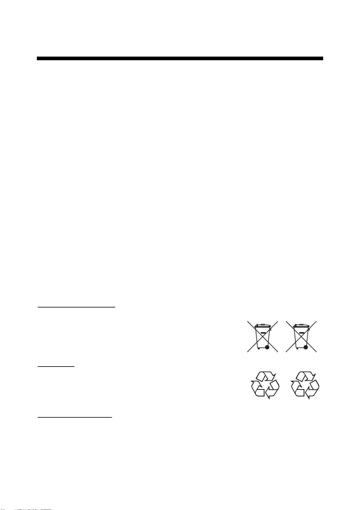
In the European Union
The crossed-out trash can symbol indicates that all types of
batteries must not be discarded in standard trash, or at a trash site.
Take the used batteries to a battery collection site according to your
national legislation and the Batteries Directive 2006/66/EU.
In the USA
The Mobius loop symbol (three chasing arrows) indicates that Ni-Cd
and lead-acid rechargeable batteries must be recycled. Take the used
batteries to a battery collection site according to local laws.
Ni-Cd Pb
In the other countries
There are no international standards for the battery recycle symbol. The number of symbols can
increase when the other countries make their own recycling symbols in the future.
i
SAFETY INSTRUCTIONS
WARNING
ELECTRICAL SHOCK HAZARD
Do not open the equipment.
Only qualified personnel
should work inside the
equipment.
Do not disassemble or modify the
equipment.
Fire, electrical shock or serious injury can
result.
Immediately turn off the power
(BATTERY, DC and AC switches in
that order) at the DCU and also turn off
off the power at the ship's mains
switchboard if water leaks into the
equipment or the equipment is emitting
smoke or fire.
Continued use can cause fatal damage to
the equipment.
WARNING
Do not disassemble the battery.
Battery fluid is harmful to the eyes and skin,
particularly the eyes. If the fluid contacts
skin or eyes, flush area with fresh water
and contact a physician immediately.
Do not dispose of the battery or acoustic
beacon in fire.
Those components may burst if disposed of
in fire. Further, dispose of the battery in
accordance with appropriate regulations.
Do not touch any electricaly conductive
parts.
Touching electrically conductive parts can
result in electrical shock. Use rubber gloves,
etc. when conducting inspection or
maintenance work.
Do not short battery terminals.
Only authorized personnel shall
disassemble the DRU.
Pressure may build up inside the unit when
it is subjected to fire or is retrieved from a
great depth.
Do not allow rain or water splash to
contact the equipment.
Fire or electrical shock can result.
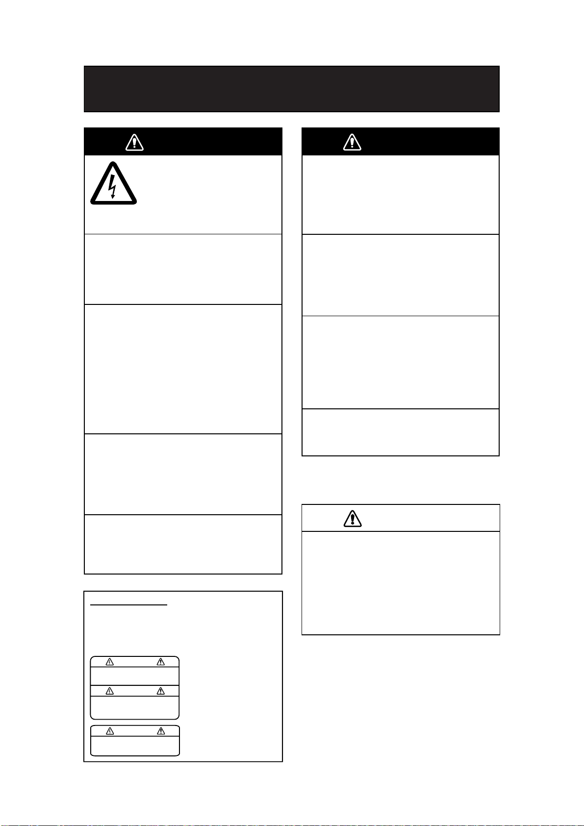
WARNING LABELS
Warning labels are attached to the DCU.
Do not remove the labels. If the label is missing or
damaged, contact a FURUNO agent or dealer
about replacement.
WARNING
To avoid electrical shock, do not
remove cover. No user-serviceable
parts inside.
Name: Warning Label 1
Type: 86-003-1011-2
Code No.: 100-236-232-10
Short can lead to bursting or fire.
CAUTION
Do not:
- use batteries of different capacities
- mix old batteries with new
- mix batteries of different makes
Batteries themselves may become
damaged or damage to electrical
parts may result.
WARNING
To avoid electrical shock, do not
remove cover. No user-serviceable
parts inside.
Name: Warning Label 2
Type: 03-129-1001-2
Code No.: 100-236-742-10
ii
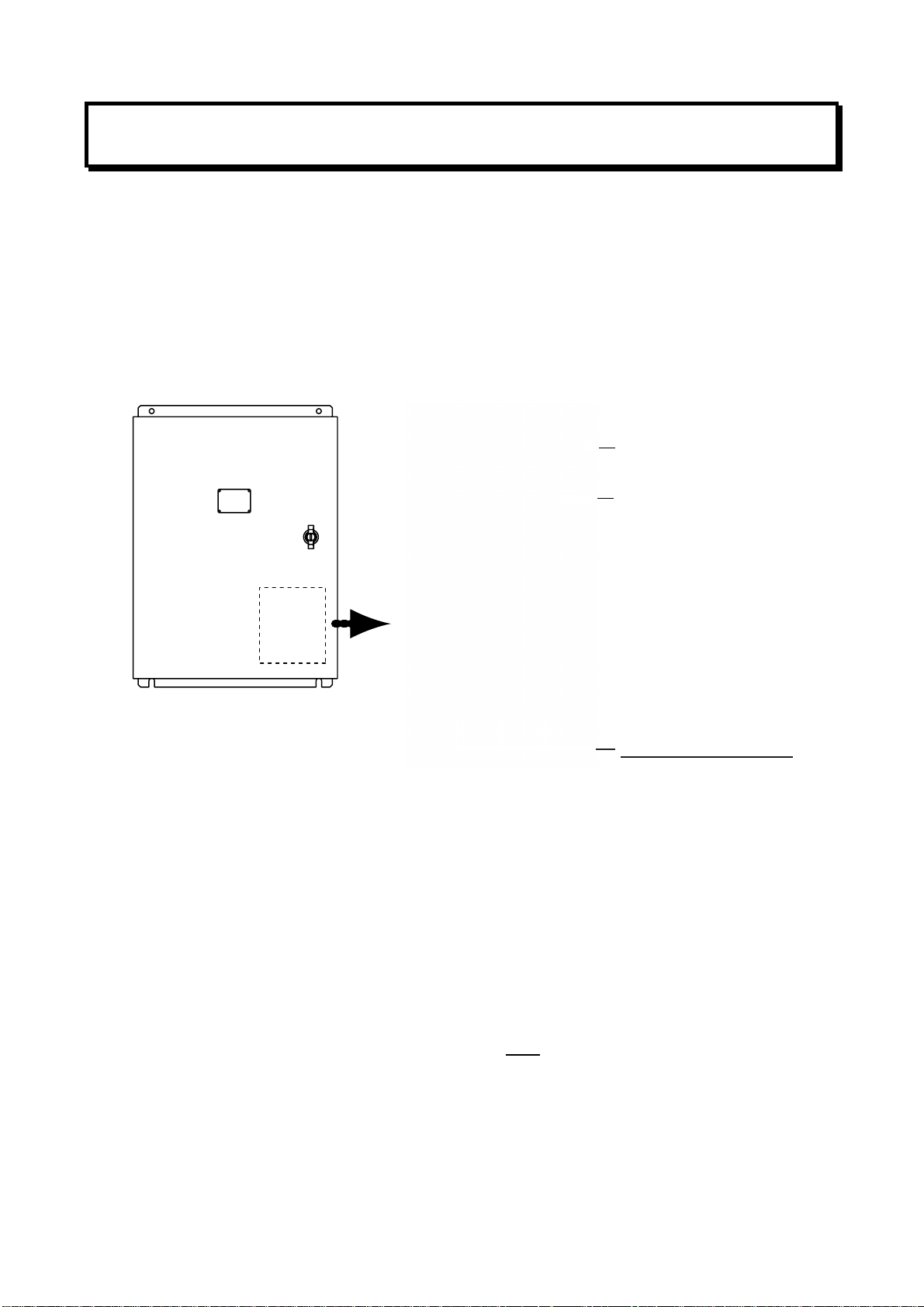
POWERING DATA COLLECTING UNIT
On the power control panel in the Data Collecting Unit (DCU), confirm that the status display
shows “- - -“ and the NORMAL LED is lit after the power has been on for two minutes. If not, see
Chapter 3.
Procedure for turning on power
1. Turn the AC breaker switch on.
2. Turn the DC breaker switch on if DC power is connected.
3. Turn the BATTERY BACKUP breaker switch on.
Status Display
NORMAL LED
Breaker switches (from left)
Battery Backup, DC, AC
Power control panel/status display inside the DCU
Error indication on Remote Alarm Panel (RAP)
If the ERROR LED (red) lights on the RAP, check the error number on its status display and refer
to the error code tables in Chapter 3.
ERROR LED
Remote Alarm Panel
iii

IF AN INCIDENT OCCURS
Press the SAVE button on the Remote Alarm Panel. Bring the HDD with you after an incident
occurs, if possible.
SAVE LED
(yellow)
SAVE button
• The SAVE LED (yellow) starts flashing and shortly thereafter lights. Then, recording to the
current memory area in the backup HDD in the Data Collecting Unit is stopped and recording
to another memory area starts. The memory in the backup HDD is divided into four areas.
If you press the SAVE button on the RAP, one recording area stops recording. If you press
the SAVE button four times, all four areas stop recording. If you pressed the SAVE button,
consult a FURUNO dealer to restore the HDD after an investigation of the incident is
completed by the authorities.
• Recording at the Data Recording Unit continues.
iv

TABLE OF CONTENTS
FOREWORD...............................................................................................vi
SYSTEM CONFIGURATION......................................................................vii
Record of PUB REV., PROG. No.............................................................viii
1. OPERATION............................................................................................ 1
1.1 Overview ...........................................................................................................................1
1.2 Operating Procedure.........................................................................................................6
1.2.1 Powering, recording........................................................................................................6
1.2.2 Stopping recording..........................................................................................................6
1.3 Operation on Remote Alarm Panel ...................................................................................7
1.4 Removing HDD at an Incident...........................................................................................8
1.5 How to Release DRU ........................................................................................................8
2. MAINTENANCE.......................................................................................9
2.1 Annual Recertification .......................................................................................................9
2.2 Cleaning ............................................................................................................................9
2.3 Software Maintenance ....................................................................................................10
2.3.1 Software list ..................................................................................................................10
2.3.2 Checking software version of system program .............................................................10
2.3.3 Checking software version of RAP ...............................................................................10
2.4 Replacing Batteries ......................................................................................................... 11
2.5 Replacing Acoustic Beacon.............................................................................................12
2.6 Replacing Backup HDD ..................................................................................................13
2.7 Replacing Fuses .............................................................................................................14
2.8 Replacing Parts...............................................................................................................14
2.9 Verifying Recording Function of the DRU.........................................................................15
2.10 Confirmation of Peripheral Devices ................................................................................16
3. TROUBLESHOOTING...........................................................................17
3.1 General Troubleshooting.................................................................................................17
3.2 Error Codes.....................................................................................................................18
3.3 Testing Display of Remote Alarm Panel..........................................................................20
4. LOCATION OF PARTS.......................................................................... 21
4.1 Parts Location .................................................................................................................21
4.1.1 Data Collecting Unit (VR-3010) ....................................................................................21
4.1.2 Data Recording Unit (VR-5020-9G or VR-5020-6G) ....................................................22
4.1.3 Junction Box (IF-8530) .................................................................................................23
4.1.4 Remote Alarm Panel (VR-3016)...................................................................................23
4.2 Parts List .........................................................................................................................24
5. INTERFACE (IEC 61162-1, IEC 61162-2)..............................................25
5.1 Data Sentences...............................................................................................................25
5.2 Interface Circuits .............................................................................................................38
5.2.1 IEC 61162-1..................................................................................................................38
5.2.2 IEC 61162-2..................................................................................................................39
APPENDIX: PLAYING BACK RECORDED DATA.................................... 40
SPECIFICATIONS.......................................................................................................SP-1
v

FOREWORD
A Word to the Owner of the VR-3000, VR-3000S
Thank you for purchasing the FURUNO Voyage Data Recorder (VDR) VR-3000, Simplified
Voyage Data Recorder (S-VDR) VR-3000S. We are confident you will discover why FURUNO
has become synonymous with quality and reliability.
What is a VDR, S-VDR?
A VDR records various data and events encountered aboard ship. The purpose of the VDR is to
help investigators locate the causes of marine incidents. There is no principle difference between
a VDR and an S-VDR. The difference is the amount of information required to be recorded. The
VDR is required to record more data than the S-VDR. Note that this manual refers to either the
VDR or S-VDR as VDR.
The revised SOLAS Chapter V requires the installation of VDRs on passenger ships of 150 GT
and above on all voyages and other ships of 3000 GT and above on international voyages and for
newly built ships on and after 1 July, 2002.
The basic VR-3000/VR-3000S consists of a Data Collecting Unit (DCU), a Data Recording Unit
(DRU), a Remote Alarm Panel (RAP) and microphones to record bridge audio. The VR-3000 is
also equipped with a Junction Box (JB), which is optional on the VR-3000S. The DCU contains
the Data Processor Unit, interface modules and backup batteries. It collects data from sensors as
required by the IMO and IEC standards. The DCU processes the incoming data and information
in the order of occurrence while old data is overwritten with new data for storage in the DRU for a
12 h period. The batteries supply power to the DCU to record bridge audio for 2 h in case of a
main ship’s power failure.
The flash memory in the DRU stores the data coming from the DCU. All essential navigation and
status data including bridge conversation, VHF communications, and radar images are recorded.
The data can be retrieved by using playback software for investigation after an incident. The DRU
components are embodied in the protective capsule. The capsule ensures survival and recovery
of the recorded data after an incident. An acoustical pinger helps locate the DRU underwater.
Features
• Reliable and fast data exchange between DCU and DRU via a single IEEE1394 cable.
• Easy commissioning and maintenance by PC downloading/uploading.
• 12-hour recording of normal sensor loading in standard memory.
• UTC time tagged for system synchronization and easy data retrieval.
• Choice of flash memory capacity in the Data Recording Unit.
• Backup hard disk (HDD) for storage and retrieval of data.
• Meets IMO A.861 (20), IEC 61996 and other relevant standards.
vi
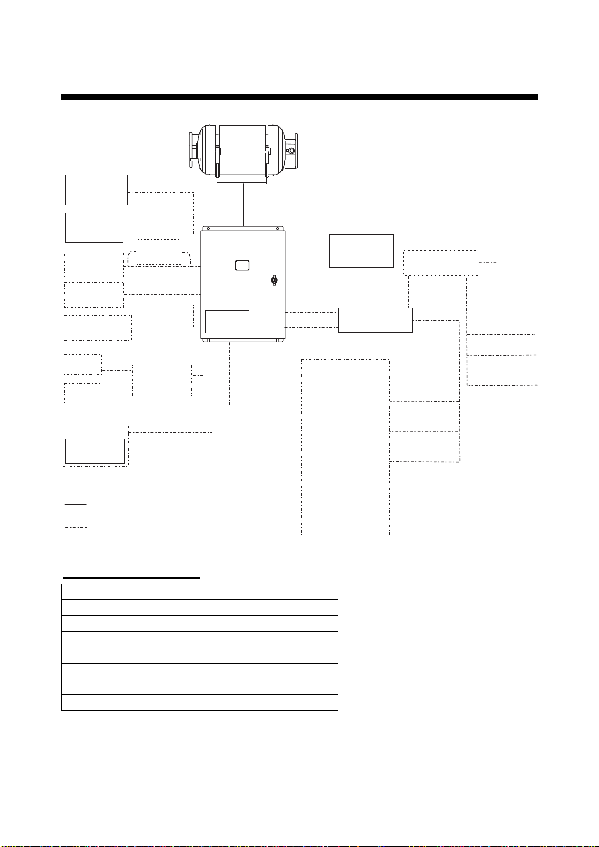
SYSTEM CONFIGURATION
Data Recording Unit (DRU)
VR-5020-6G/VR-5020-9G
Waterproof MIC
VR-3012W
Bridge MIC
VR-5011
VHF Audio
IEC 61162
serial data
Alarm Monitoring
System
No. 1
Radar
No. 2
Radar
PC
Live Player V4
VR-3020
: Standard supply equipment and cable
: Optional supply equipment and cable
: Local supply equipment and cable
* Optional with VR-3000S
Max. 6 ch
VHF I/F
IF-5200
Serial (Max. 8 ch)
Radar Video
SW Interface
IF-1000RVC
Max. 2 ch
Max.
2 ch
Data Collecting
Unit (DCU)
VR-3010
Radar I/F
RI-3010*
100-230 VAC
24 VDC
Remote Alarm
Panel (RAP)
VR-3016
Junction Box (JB)
IF-8530*
GPS
Speed log
Heading
Echosounder
Autopilot
Engine telegraph
Steering gear
M/E remote system
Main air compressor
Bow thruster
Shell door system
Watertight doors
Fire doors
Anemometer
Fire detection
Main alarms
Others
Junction Box (JB)
IF-8530 (max. 2)
Serial
(1ch)
Serial (Max. 8)
Analog
(Max. 16 ch)
Digital (Max. 64 ch)
24 VDC
Analog
(Max. 16 ch)
Digital (Max. 64 ch)
Serial (1 ch)
Environmental category
DCU Protected from weather
DRU Exposed to weather
RAP Protected from weather
Bridge MIC Protected from weather
Waterproof MIC Exposed to weather
VHF I/F unit Protected from weather
JB Protected from weather
Radar Video SW Interface Protected from weather
For the S-VDR, where it is impossible to obtain radar data, the AIS target data should be recorded
as a source of information from other ships. (Ref. IMO Res.MSC.163(78), section 5.4.7.)
vii
RECORD OF PUB REV., PROG. NO.
Revision No.,
Date of Revision
A
Apr. 19, 2006
A1
June 2, 2006
B
June 16, 2006
C
July 24, 2006
D
May 17, 2007
E
July 9, 2008
F
Dec 15, 2008
G
Jul. 20, 2010
Program No.
(software)
VR-3000 SYSTEM
2450031-01
RAP
2450026-01
Same as above
Same as above
Same as above
Same as above
VR-3000 SYSTEM
2450031-02
RAP
Same as above
Same as above
Same as above
Outline of Revision
st
1
printing.
Revised system configuration drawings to include
Waterproof MIC.
Changed error code no. as follows:
035→034 Storage failure
041→042 Grabber failure
048→046 DRU Index error
Revised specifications
All pages revised.
Added beacon cover.
Changed flush disk.
For new standard.
Miner program modification
Miner program modification
Revised the replacing parts.
Added error codes; 173, 174, 431 and 432.
Revised section 2.9.
viii
1. OPERATION
1.1 Overview
The VR-3000/VR-3000S consists of Data Collecting Unit (DCU), Data Recording Unit (DRU),
Remote Alarm Panel (RAP), Junction Box (JB, optional supply with VR-3000S) and bridge
microphone units. The VDR system continuously stores data from the past 12 hours onto the
Flash Memory in the capsule, erasing the oldest data stored as new data is recorded. The data to
be recorded includes the following:
Parameters to be recorded IEC 61162 formatter Notes
Date and time ZDA
Ship’s position and datum used GNS and DTM
Speed (water and/or ground) VBW
Heading (true) HDT
Heading (magnetic) HDG
AIS-VHF data-link message VDM
AIS-VHF data-link own-vessel message VDO
Depth (echo sounder) DPT
Alarms ALR
Rudder order/response manual RSA
Rudder order/response automatic HTC, HTD
Engine order/response RPM, XDR
Hull openings, watertight doors XDR
Accelerations and hull stress XDR, ALR
Wind speed and direction MWV
VDR alarm output $VRALR
Radar data
Bridge audio
VHF communication audio
No requirement for S-VDR to
send alarm messages
Power supply precaution
If ship’s mains power source (100-230 VAC) and emergency source fail, the VR-3000/VR-3000S
continues to record bridge audio for 2 h from backup batteries. When using the backup batteries,
suspend power to the IF-8530 Junction box..
1
Continuity of storing data
The VDR should be provided with power to store data for 12 h on a first-in, first-out basis.
Recording is terminated only under the following circumstances:
a) During essential maintenance while the vessel is in port.
b) When the vessel is laid-up.
c) In case of emergency, when the backup HDD is removed.
Data Collecting Unit
The DCU mainly consists of Data Processor Unit and Power Control Panel. The DCU includes
two 12 V backup batteries with a lifetime of approximately four years. The DCU collects the data
from various sensors and radar and records them in the DRU and backup HDD.
Recording interval of data and audio is as follows:
- Radar video signal: every 15 seconds
- Bridge and VHF audio: real time
- IEC sentences: when received
- Analog and digital data: every second
LEDs: Light (green) when respective power is applied.
Status Display
LEDs (from left)
SAVE (yellow):
When stopping the data
recording, this starts
blinking from OFF state,
then lights steadily.
If the HDD is disconnected,
this LED lights also.
NORMAL (Green):
On at normal operation.
ERROR (red):
Lights for error.
Breaker switches (from left)
Battery Backup, DC, AC
2
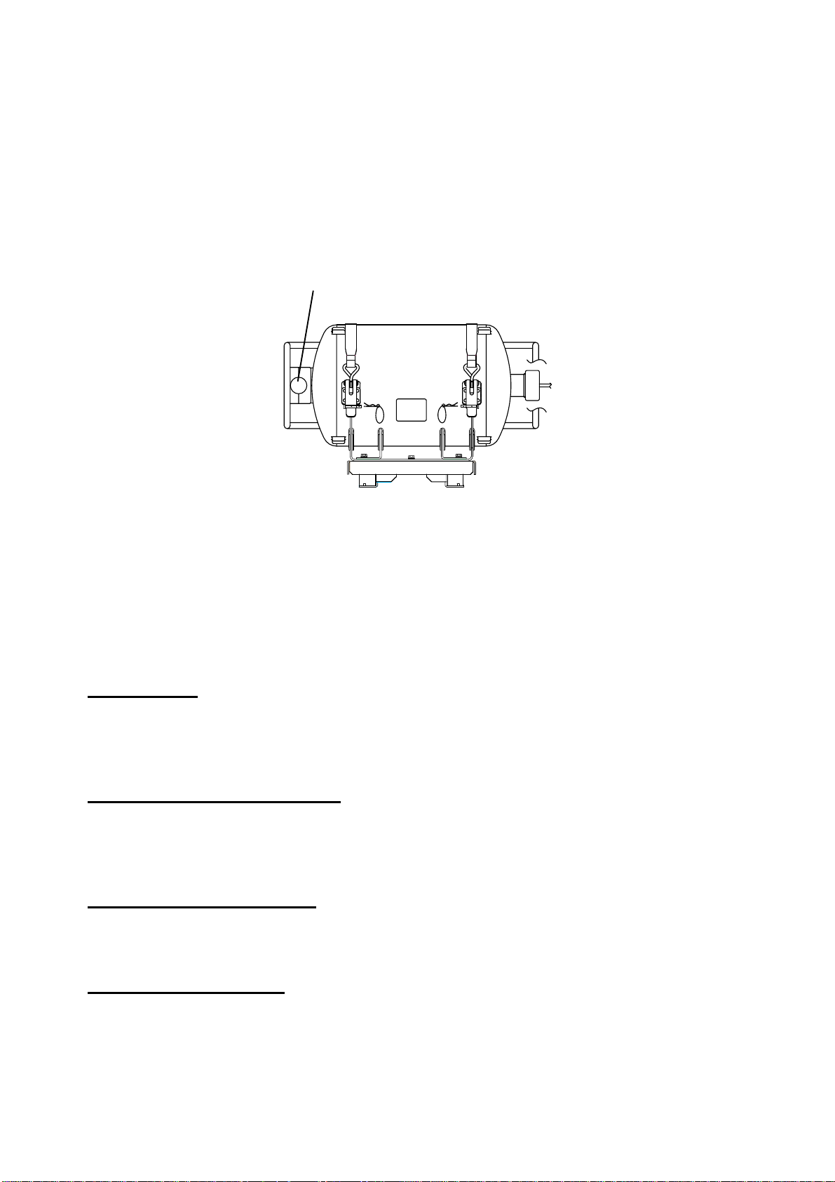
Data Recording Unit
The Data Recording Unit is housed in a highly visible protective capsule which can withstand a
fire of 1100°C for 1 hour and deep-sea pressure of 6000 m.
The underwater acoustic beacon (pinger) on the capsule automatically transmits 10 ms pulses at
37.5 kHz for at least 30 days when it is submerged in water. The expected life of the beacon is 6
years. The DRU is connected to the Data Collecting Unit (DCU) with a non-halogen FireWire
cable (IEEE1394).
Underwater Acoustic Beacon
Data Recording Unit
Integrity
The recording integrity is ensured by continuous monitoring of power supply, record function, bit
error rate, and microphone functionality. Visual alarm is generated for malfunction of any of these.
Alarm status is also indicated by relay contacts.
Data items to be recorded
Date and time
Date and time are obtained from an external GPS navigator referenced to UTC. Time information
is recorded at intervals of 1 s. Without date and time data, no data except audio signal is
recorded.
Ship’s position and datum used
Latitude, longitude and datum are obtained from a GPS navigator, Loran-C receiver or other
EPFS or INS available on standard digital interface. The source of data is identifiable on
playback.
Speed (water and/or ground)
Speed through the water (STW) or speed over the ground (SOG) is recorded at intervals of 1 s.
The resolution is 0.1 kt. Transverse speed is also indicated when available on board.
Heading (true, magnetic)
Heading is recorded at intervals of 1 s to a resolution of 0.1°. The data is labeled G
(gyrocompass), GPS, GLONASS, MAG. If heading information is not available in IEC 61162
format, an appropriate interface may be necessary.
3

AIS-VHF data-link message, AIS-VHF data-link own-vessel message
Where there is no commercial off-the-shelf interface available to obtain radar data then AIS target
data shall be recorded as a source of information regarding other ships, otherwise AIS
information may be recorded additionally as a beneficial secondary source of information on both
other and own ship.
The VDM message (UAIS VHF Data-link) shall be recorded in such a way that all target data
available from the onboard AIS are acquired. If the VDO message (UAIS VHF Data-link
Own-vessel report) is recorded, this shall be additional to the recording of individual sensor data.
Depth (echo sounder)
Depth under keel up to a resolution of 0.1 m as available on the ship is recorded.
Alarms
The status of all IMO mandatory alarms is recorded individually with ID number and time stamp.
Audible alarms from the alarm units are stored simultaneously by the bridge audio microphones.
Rudder order/response
Rudder order and response angles are recorded up to a resolution of 1° as available on the ship.
The rudder information is recorded. If more than one rudder is provided, the circuitry can be
duplicated.
Engine order/response
The DCU obtains the engine order and response from the engine telegraph or direct engine
control. The signal level is normally 0-10 V. The engine parameters with shaft revolution and
ahead/astern indicators are recorded to a resolution of 1 rpm.
All order and response from bow, stern, thruster, tunnel thrusters and controllable pitch propellers
shall be recorded. The S-VDR shall record this data if said serial data is available.
Hull openings, watertight doors
Inputs digital or RS-422 serial can be connected individually. The data is received at intervals of 1
s and stored with time stamps. Serial data sentence XDR is received at a data rate of 1,200-9,600
baud.
Accelerations and hull stresses
The DCU obtains signals from appropriate hull stress and response monitoring devices. The
inputs are recorded individually and stored with time stamps. Serial data sentence XDR is
received at a data rate of 1,200-9,600 baud.
Wind speed and direction
The DCU obtains the signal from appropriate wind speed and direction sensor. The inputs are
recorded individually and stored with time stamps. Serial data sentence XDR is received at a data
rate of 1,200-9,600 baud.
VDR alarm output
There is no requirement for the S-VDR to send alarm messages. If, as an option, such messages
are sent then the appropriate sentence format is ALR.
4

Radar data
Radar image including range rings, EBLs, VRMs, plotting symbols, radar maps, parts of SENC,
voyage plan, and other essential navigational indications, is recorded in the DRU via the interface
in the DCU which is connected to the buffered video output of the radar display unit. One
complete picture frame is captured at intervals of 15 s.
The radar display complying with IEC 60936-1 should have a buffered output (VESA DMTS
compatible) with resolutions between 640 x 480 and 1280 x 1024, and can be directly connected
with the VDR. Scanning may be interlaced or non-interlaced.
Bridge audio
Up to six microphones are supplied as standard to record conversation at conning station, radar
display and chart table. If possible, the microphones should be positioned to capture the audio
from the intercom, public address system, and audible alarms on the bridge. The microphones
are labeled Mic1, Mic2, etc. Microphone captures conversation in the bridge, audio signals from
equipment and sound from machinery. The microphone generates a test beep every 12 hours
which is also recorded. The microphone picks up audio signals ranging from 150 to 6000 Hz.
Communications audio
A maximum of two VHF communications are recorded for both transmitted and received audio
signals. The VHF radio connections are labeled VHF1 and VHF2.
5

1.2 Operating Procedure
The VDR comes with a key to lock the DCU to protect against any unauthorized access. The key
must be kept securely after installation.
1.2.1 Powering, recording
On the power control panel in the DCU, turn on the AC SUPPLY MAINS, DC SUPPLY MAINS and
BATTERY BACK-UP switches in this order. Confirm that the NORMAL LED on the power control
panel and RAP lights. The VDR records data automatically in the DRU and backup HDD.
NORMAL LED
REMOTE ALARM PANEL
Breaker switches (from left)
Battery Backup, DC, AC
POWER CONTROL PANEL
NORMAL LED
1.2.2 Stopping recording
Recording is terminated only under the following conditions:
- During essential maintenance purposes while the vessel is in port.
- When the vessel is laid-up.
To stop recording, turn off the BATTERY BACKUP, DC SUPPLY MAINS and AC SUPPLY MAINS
switches in this order. DO NOT turn off the system by the main breaker while the BATTERY
BACKUP switch is on. If this is done, the system operates on the batteries. The system stops
after running on batteries after 2 hours.
6

1.3 Operation on Remote Alarm Panel
No power switch is provided on the Remote Alarm Panel; it is turned on and off by the power
switch on the DCU. When the ERROR LED (red) on the Remote Alarm Panel is on, identify the
error by checking code number in the error code tables in Chapter 3. The buttons on the Remote
Alarm Panel work as described in the figure below.
Buzzer
DIMMER:
Adjust panel backlighting;
Setting range: 0 - 10
Default: 8 (Just after
power on)
At setting 0: ERROR
LED lights at level 1.
Other LEDs are off.
Display software version
no. (pressed together).
TEST: Tests LCD.
ACK: Silences buzzer.
SAVE: Stops recording onto current memory area in the backup
HDD and starts recording onto another menory area.
Status Display
--X: Indicates that X no. of recording
areas exist. (X: 4, 3, 2, 1)
---: Recording area is not yet known.
(at startup or when recognizing HDD)
LEDs (from left)
SAVE (yellow):
Starts blinking from OFF
state when recording is
stopped, then lights
steadily.
If the HDD is disconnected,
this LED lights also.
NORMAL (Green):
On at normal operation.
ERROR (red):
Lights for error.
Note: The buzzer sounds every time the radar connected to the VDR is turned off. Press the
ACK button to silence the alarm.
NOTICE
After pressing the SAVE button four times, data
will not be recorded. Replace the HDD with an
initialized one, or contact a FURUNO agent for
ecessary procedure.
SAVE button
If you press the SAVE button, the current memory area in the backup HDD stops recording and
another area starts recording. If an incident occurs, press this button immediately. If another
incident occurs, press the button again. The memory in the backup HDD is divided into four areas.
When you press the SAVE button, the number of recording area in the HDD is reduced by one.
After saving is completed, the buzzer sounds intermittently for 10 seconds. However, if an alarm
is violated during the saving, the alarm buzzer has priority. If you press the SAVE button four
times, all four areas stop recording. To remove the HDD, see paragraph 1.4.
If you pressed the SAVE button during an incident, consult a FURUNO dealer to restore the HDD
after the authorities complete an investigation of the incident.
7
 Loading...