

Page 1

A
Installation Manual
MULTI FUNCTION DISPLAY
Model TZTBBX
SAFETY INSTRUCTIONS ................................................................................................i
SYSTEM CONFIGURATION ...........................................................................................ii
EQUIPMENT LISTS........................................................................................................ iv
1. MOUNTING.................................................................................................................1
1.1 Mounting Considerations ......................................................................................................1
1.2 How to Install the Processor Unit..........................................................................................1
2. WIRING.......................................................................................................................3
2.1 Precautions for Tabletop Mounting.......................................................................................3
2.2 Interface Connections (rear of the unit) ................................................................................3
2.3 Power Cable .........................................................................................................................4
2.4 MULTI Cable.........................................................................................................................4
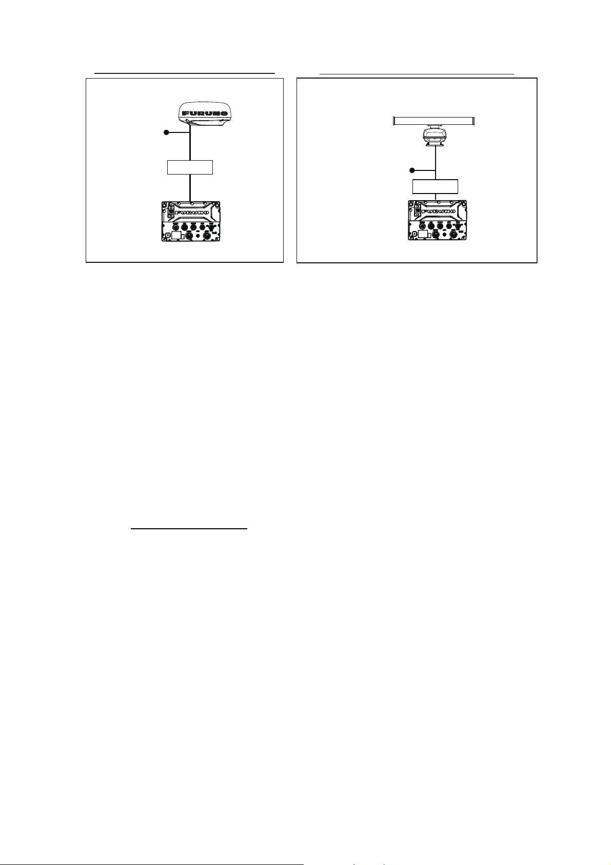
2.5 DRS Radar Sensor Connections ..........................................................................................5
2.6 Network Connection with Other TZT Series Units ................................................................6
2.7 NMEA 2000 Connector .........................................................................................................6
2.8 Example TZTBBX System Configuration............................................................................10
3. HOW TO SET UP THE EQUIPMENT....................................................................... 11
3.1 How to Set Time Zone, Time Format and Language..........................................................13
3.2 How to Set Units of Measurement ......................................................................................14
3.3 Initial Setup .........................................................................................................................15
3.4 How to Set Up the Radar (For the service technician only)................................................21
3.5 How to Set Up the Fish Finder............................................................................................23
3.6 Wireless LAN Setting ..........................................................................................................29
3.7 Ferry Mode..........................................................................................................................30
3.8 How to Manage Your Charts...............................................................................................30
3.9 IP Camera Setup ................................................................................................................35
APPX. 1 JIS CABLE GUIDE....................................................................................AP-1
PACKING LIST(S) ....................................................................................................... A-1
OUTLINE DRAWING(S) .............................................................................................. D-1
INTERCONNECTION DIAGRAM(S) ........................................................................... S-1
www.furuno.com
ll brand and product names are trademarks, registered trademarks or service marks of their respective holders.
Page 2
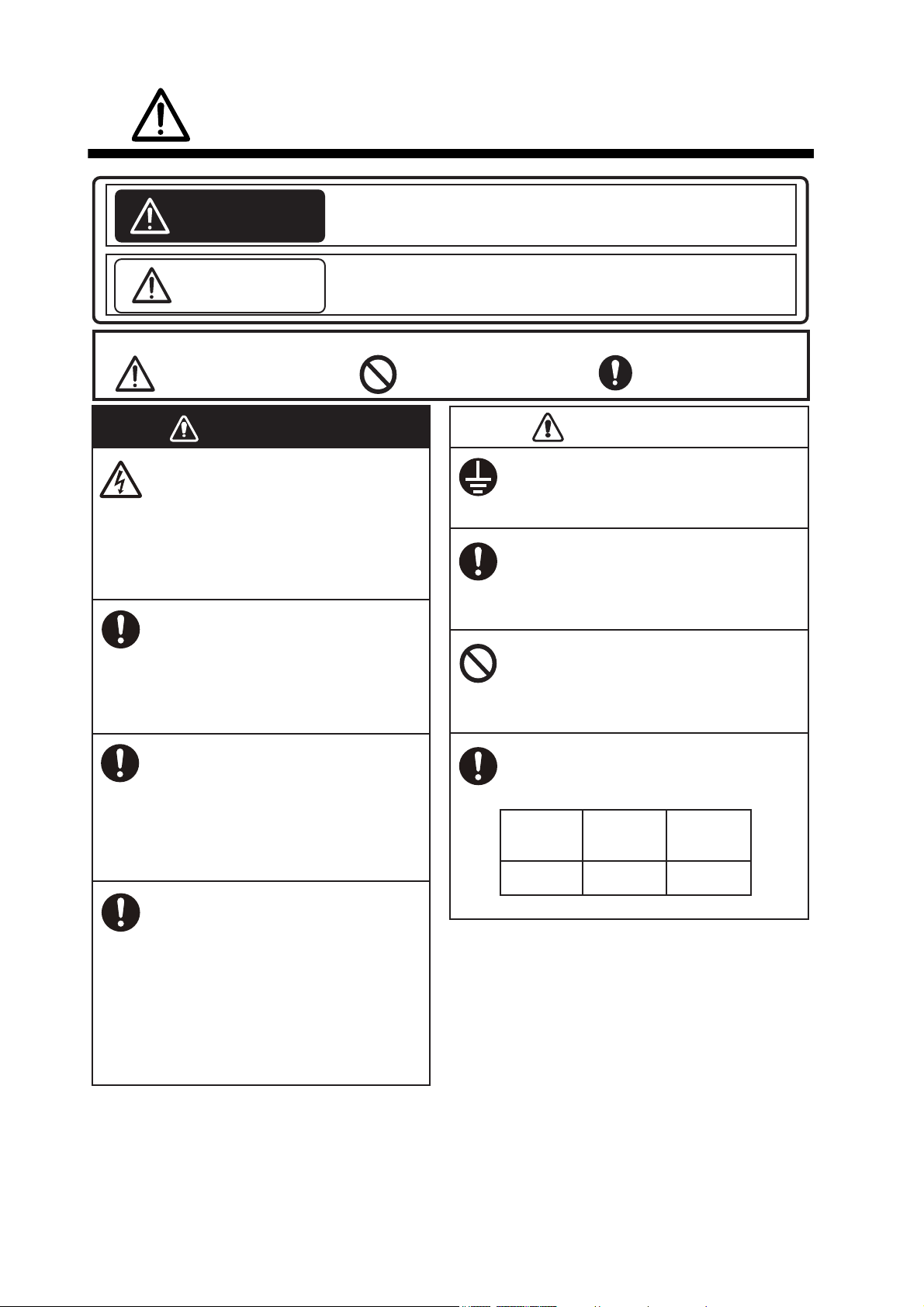
Indicates a potentially hazardous situation which, if not
avoided, could result in death or serious injury.
Indicates a potentially hazardous situation which, if not
avoided, may result in minor or moderate injury.
WARNING
CAUTION
Warning, Caution Prohibitive Action Mandatory Action
WARNING
ELECTRICAL SHOCK HAZARD
Do not open the equipment
unless totally familiar with
electrical circuits.
Only qualified personnel should
work inside the equipment.
Turn off the power at the
switchboard before beginning
the installation.
Fire or electrical shock can result
if the power is left on.
CAUTION
Be sure that the power supply is
compatible with the voltage
rating of the equipment.
Connection of an incorrect power
supply can cause fire or damage
the equipment.
Use the proper fuse.
Use of an incorrect fuse may
damage the equipment.
The front panel is made of glass.
Handle it with care.
Injury can result if the glass breaks.
Observe the following compass safe
distances to prevent interference to a
magnetic compass:
Standard
compass
Steering
compass
(Examples of symbols)
Model
Ground the equipment to prevent
electrical shock and mutual interference.
If your vessel is configured with
an autopilot system, install an
autopilot control unit (or emergency autopilot stop button) at
each helm station, to allow you
to disable the autopilot in an
emergency.
If the autopilot cannot be disabled,
accidents may result.
TZTBBX
0.35 m
0.30 m
SAFETY INSTRUCTIONS
i
Page 3
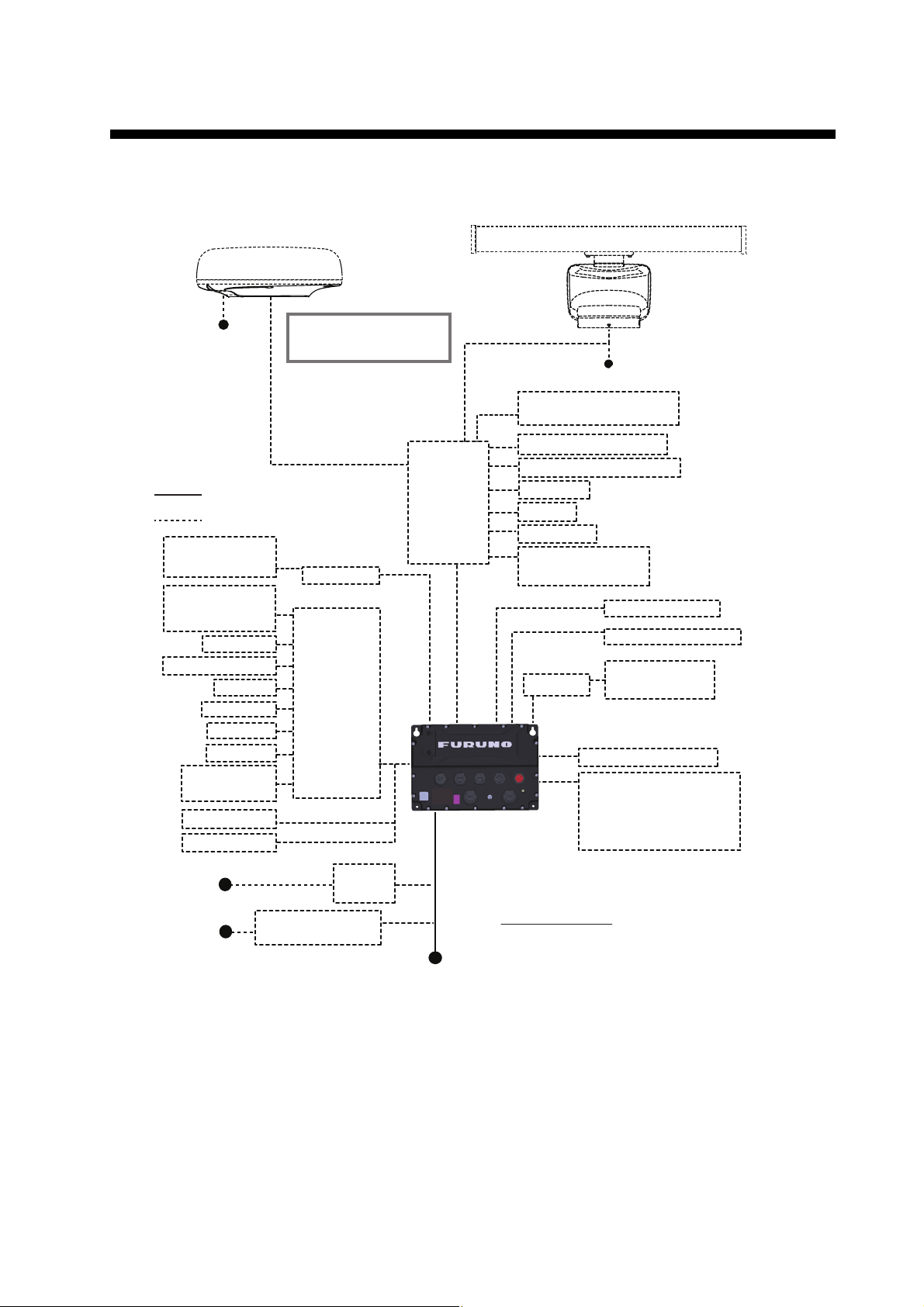
SYSTEM CONFIGURATION
Category of units
Antenna unit: Exposed to the weather.
Other units: Protected from the weather.
*1: A maximum of 3 units of HUB-101 can be connected.
*
2
: With the Ethernet HUB, up to six NavNet TZtouch series units can be connected (up to four units when
the TZT2BB is included).
NavNet TZtouch (TZT9/14/BB) and TZTL12F/15F of NavNet TZtouch2 cannot be
connected. For connection combinations, see page xxi.)
*3: Use a commercially available PoE hub. The NETGEAR GS108PE has tested as compatible.
The basic functions of the hub were verified, however the compatibility of all functions were not checked.
FURUNO cannot guarantee proper operation.
*4:
Available when FUSION-Link compatible equipment is connected via Ethernet.
*
5
: When connected to a USB host device using USB OTG (USB), this unit operates as a touch operation
output device.
*
6
: Only DRS6A-NXT supports 12 to 24 VDC
*
7
: DRS4D X-Class can only be used in Japan.
*
8
: DRS2D-NXT and DRS4D-NXT cannot be used in Japan.
100/110/115/220/
230 VAC
1
I
, 50/60 Hz
100-230 VAC
1I, 50/60Hz
Junction Box
FI-5002
GP-330B
FI-50/70
FA-40/60
IF-NMEA2K2
12 to 24 VDC
NAVpilot Series
Ethernet
Hub
*1, *2
HUB-101
BBDS1, DFF series
FAX-30
FUSION-Link
compatible equip.
*4
Event Switch
External Buzzer
External Power Switch
NMEA 0183 Output
Remote Control
Unit MCU-005
Radar Sensor (radome type)
DRS4DL+/DRS4D X-Class*7/
DRS2D-NXT
*8
/DRS4D-NXT
*8
12 to 24 VDC
: Standard supply
: Optional supply, local supply
Radar Sensor
(open type)
DRS6A X-Class/DRS12A X-Class/DRS25A X-Class
DRS6A-NXT/DRS12A-NXT/DRS25A-NXT
24 VDC
*6
Select an antenna type:
Radome or Open
Multi Beam Sonar DFF-3D
IP Camera
PoE Hub
*3
FAR-2xx7/2xx8 series
FAR-1518/1528
SCX-20
SC-30/33
IF-NMEAFI
NTSC/PAL Camera
Remote Control
Unit MCU-006/
MCU-006H
FA-30/50
FUSION-Linkcompat. equip.
Rectifier
PR-62
AC/DC Power
Supply Unit PR-241
USB Hub
HDMI Source
USB Host/Device
*5
Touch Monitor
(HDMI OUT)
Note: Update the software of
these radars to the following
version or later before using:
• DRS6A-NXT/DRS12A-NXT/
DRS25A-NXT: ver. 01.02
• DRS6A X-Class/DRS12A X-Class/
DRS25A X-Class: ver. 02.06
TZTBBX
ii
Page 4
SYSTEM CONFIGURATION
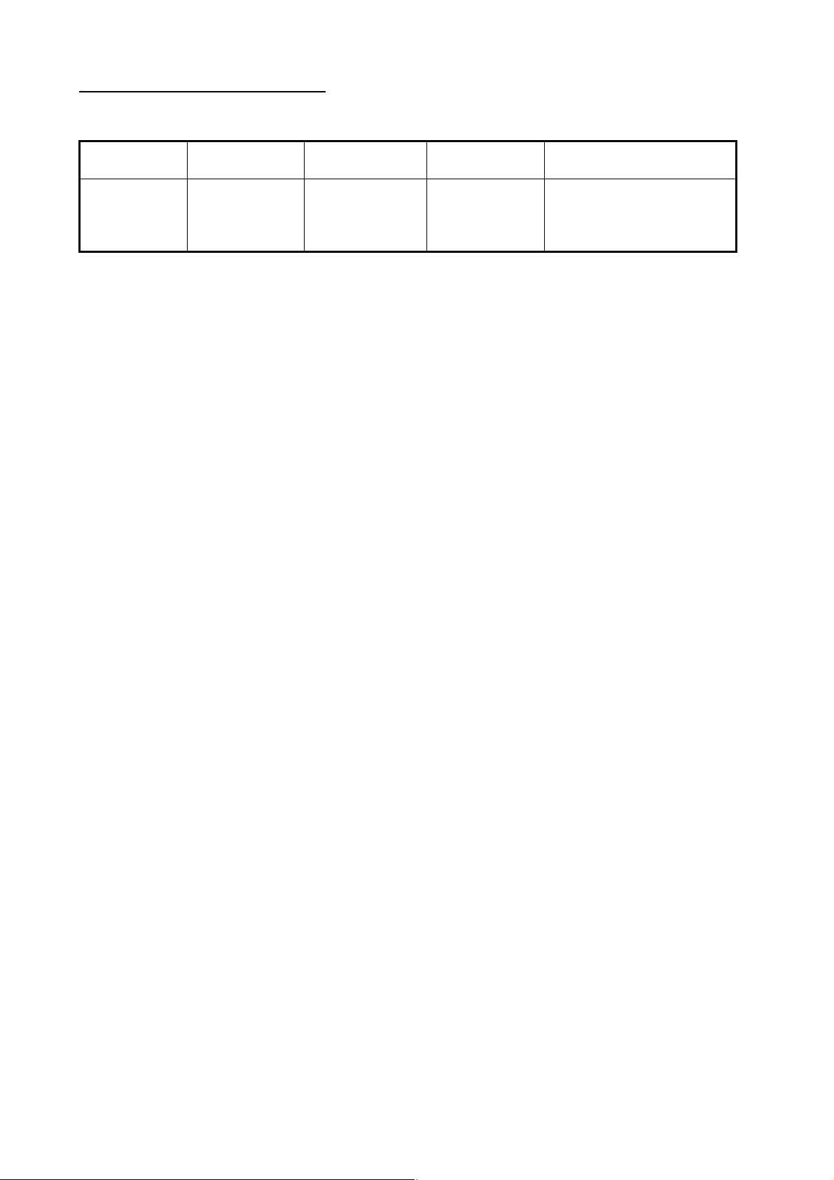
TZT series network connections
The TZT series can be connected on the same network in the following combinations.
TZtouchXL:
TZTBBX/10X/
13X/16X/22X/
24X
*1
: Version 9.70 or later
*2
: Version 3.70 or later
TZtouch:
TZT9/14/BB
TZtouch2:
TZTL12F/15F
TZtouch2:
TZT2BB
*1
TZT9F/12F/16F/19F
No No Yes Yes
TZtouch3:
*2
iii
Page 5
EQUIPMENT LISTS
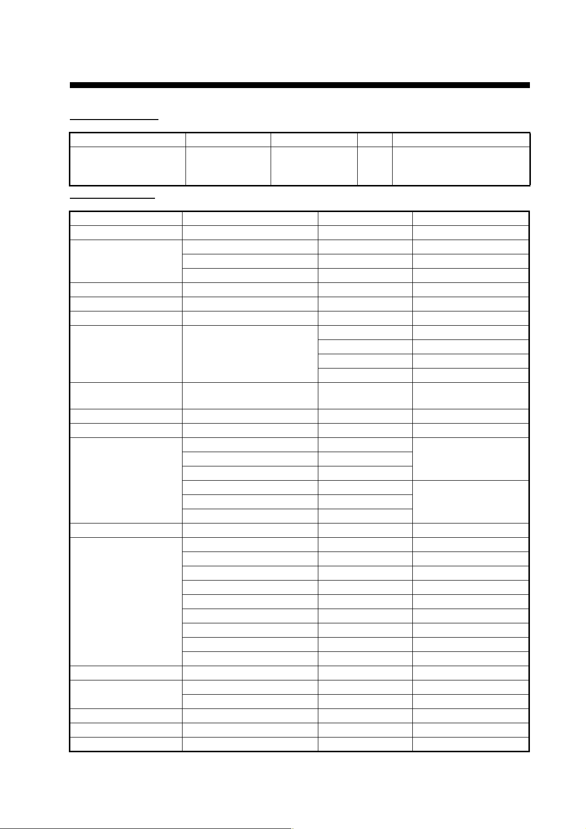
Standard supply
Name Type Code No. Qty Remarks
Multi Function Display TZTBBX -
Optional supply
Name Type Code No. Remarks
NMEA Data Converter IF-NMEA2K2 000-020-510
Remote Control Unit MCU-005 000-035-097
MCU-006 000-042-803
MCU-006H 000-042-804
Junction Box FI-5002 005-008-400
Ethernet HUB HUB-101 000-011-762
Joint Box TL-CAT-012 000-167-140 For LAN network
Rectifier PR-62 000-013-484 100 VAC
000-013-485 110 VAC
000-013-486 220 VAC
000-013-487 230 VAC
AC/DC Power Supply
Unit
Ferrite Core OP86-11 001-594-450 For PR-241
External Buzzer OP03-136 000-086-443 Buzzer: PKB5-3A40
Network (LAN) Cable FRU-RZWPNWP-002G 001-646-960 Single connector
MULTI Cable FRU-CCCAF14-R001G 001-647-020
NMEA Cable Assy. FRU-NMEA-PMMFF-010 001-533-060 1 m, two connectors
Cable Assy. FRU-HDDAP-005G 001-656-600 HDMI cable
USB Cable FRU-UPCAP300UB 001-647-040 USB-A/USB-B cable
USB OTG Cable FRU-MAEF05-MBJ0300G 001-646-940 Micro USB cable
User’s Guide E42-02210-* 000-200-313-1* For MCU-006
Operator’s Manual OME-45240-* 000-200-138-1*
PR-241 000-037-820
FRU-RZWPNWP-005G 001-646-980
FRU-RZWPNWP-010G 001-647-000
FRU-RZWPWP-002G 001-653-250 Dual connector
FRU-RZWPWP-005G 001-653-260
FRU-RZWPWP-010G 001-653-270
FRU-NMEA-PMMFF-020 001-533-070 2 m, two connectors
FRU-NMEA-PMMFF-060 001-533-080 6 m, two connectors
FRU-NMEA-PFF-010 001-507-010 1 m, single connector
FRU-NMEA-PFF-020 001-507-030 2 m, single connector
FRU-NMEA-PFF-060 001-507-040 6 m, single connector
FRU-MM1MF1MF1001 001-507-050 T connector
FRU-MM1000000001 001-507-070 Male, terminator
FRU-MF000000001 001-507-060 Female, terminator
FRU-UAP300UAJC-30G 001-646-920 USB-A/USB-A cable
Including installation materi-
1
als, accessories and spare
parts.
waterproofed
waterproofed
iv
Page 6

1. MOUNTING
1.1 Mounting Considerations
When selecting a mounting location, keep the following points in mind:
• Install the units indoors.
• Locate the units away from water splash.
• The operating temperature range of the processor unit is -15°C to 55°C (5°F to
131°F). Be sure the mounting location satisfies this requirement.
• Locate the units away from exhaust pipes and vents.
• The mounting locations should be well ventilated.
• Mount the units where shock and vibration are minimal.
• Keep the units away from electromagnetic field-generating equipment such as motors and generators.
• Referring to the outline drawings at the back of this manual, leave sufficient room
for service and maintenance. Also, leave slack in cables for maintenance and servicing ease.
• A magnetic compass may receive interference if it is placed too close to these units.
Observe the compass safe distances noted in the safety instructions to prevent interference to the magnetic compass.
• The processor unit is equipped with an internal LAN antenna and should be installed in a location where the signal is not interrupted or halted by obstructions.
If you cannot install the processor in an obstruction-free location, connect the
processor unit to a wireless LAN router via LAN cable to establish an ETHERNET
connection.
1.2 How to Install the Processor Unit
The Processor Unit (TZTBBX) must be installed on a flat surface (such as a floor
mount) or on a bulkhead.
1.2.1 Bulkhead installation
1. Referring to the outline drawing at the back of this manual, drill four holes for the
mounting screws (self-tapping 520, supplied as installation materials).
2. Fit two screws to the upper holes, leaving sufficient thread exposed to hang the
processor unit.
1
Page 7
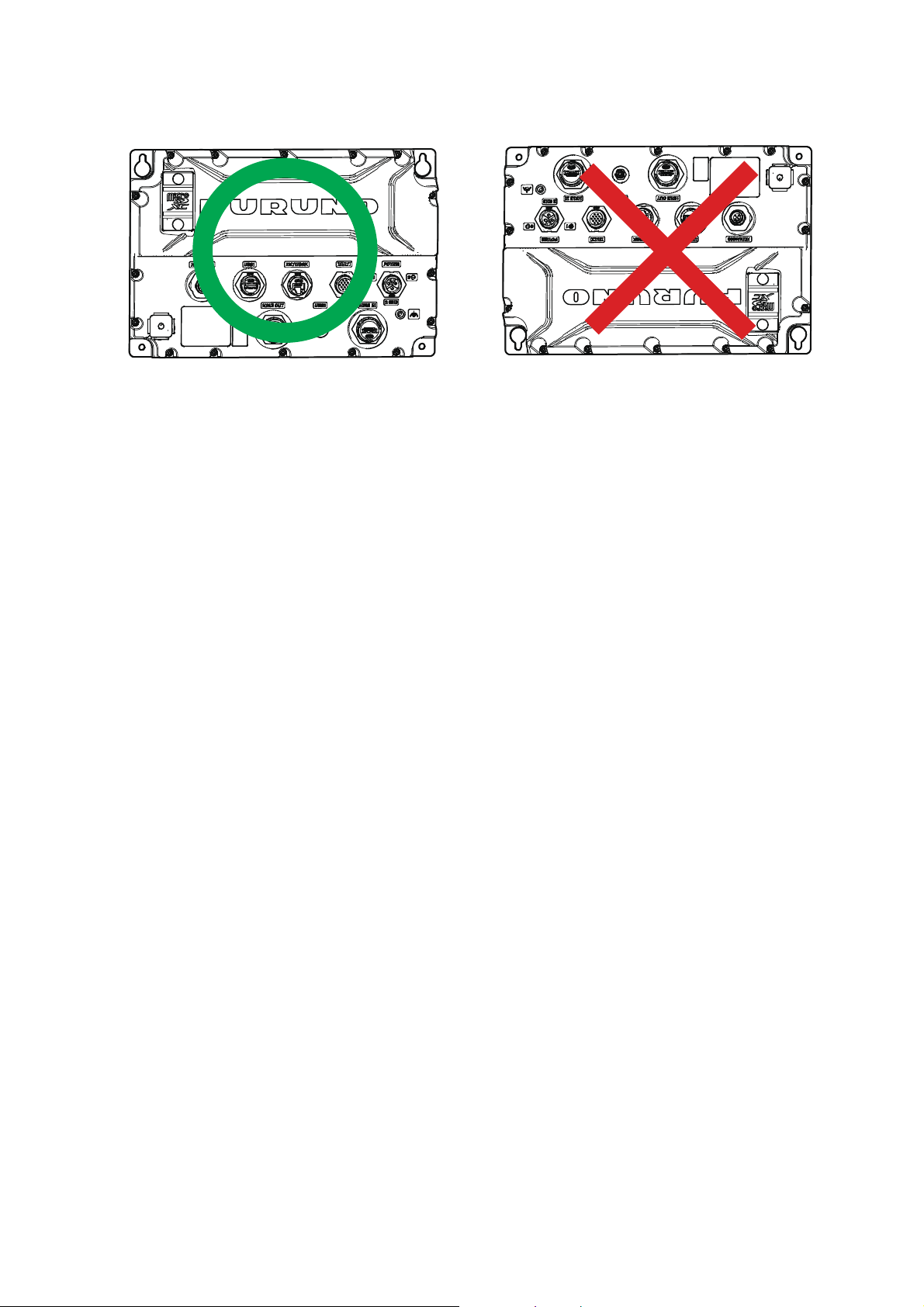
3. Hang the processor unit on the two fitted screws, taking care the that processor is
correctly oriented, with the cables and connectors facing downwards.
4. Loosely fasten two screws to the bottom two holes.
5. Fasten all four screws evenly, securing the processor unit to the installation location.
1.2.2 Flat surface (floor mount) installation
1. MOUNTING
1. Referring to the outline drawing at the back of this manual, drill four holes for the
mounting screws (self-tapping 520, supplied as installation materials).
2. Fit two screws to the upper holes, leaving sufficient thread exposed to fit the processor unit.
3. Slide the processor unit on the two fitted screws.
4. Loosely fasten two screws to the bottom two holes.
5. Fasten all four screws evenly, securing the processor unit to the installation location.
2
Page 8
2. WIRING
Processor
Unit
Connector
HDMI INHDMI INHDMI OUTHDMI OUT
USB1USB1 MULTIMULTI
NMEA2000NMEA2000 NETWORKNETWORK
POWERPOWER
USB2USB2 Grounding
wire
Grounding
wire
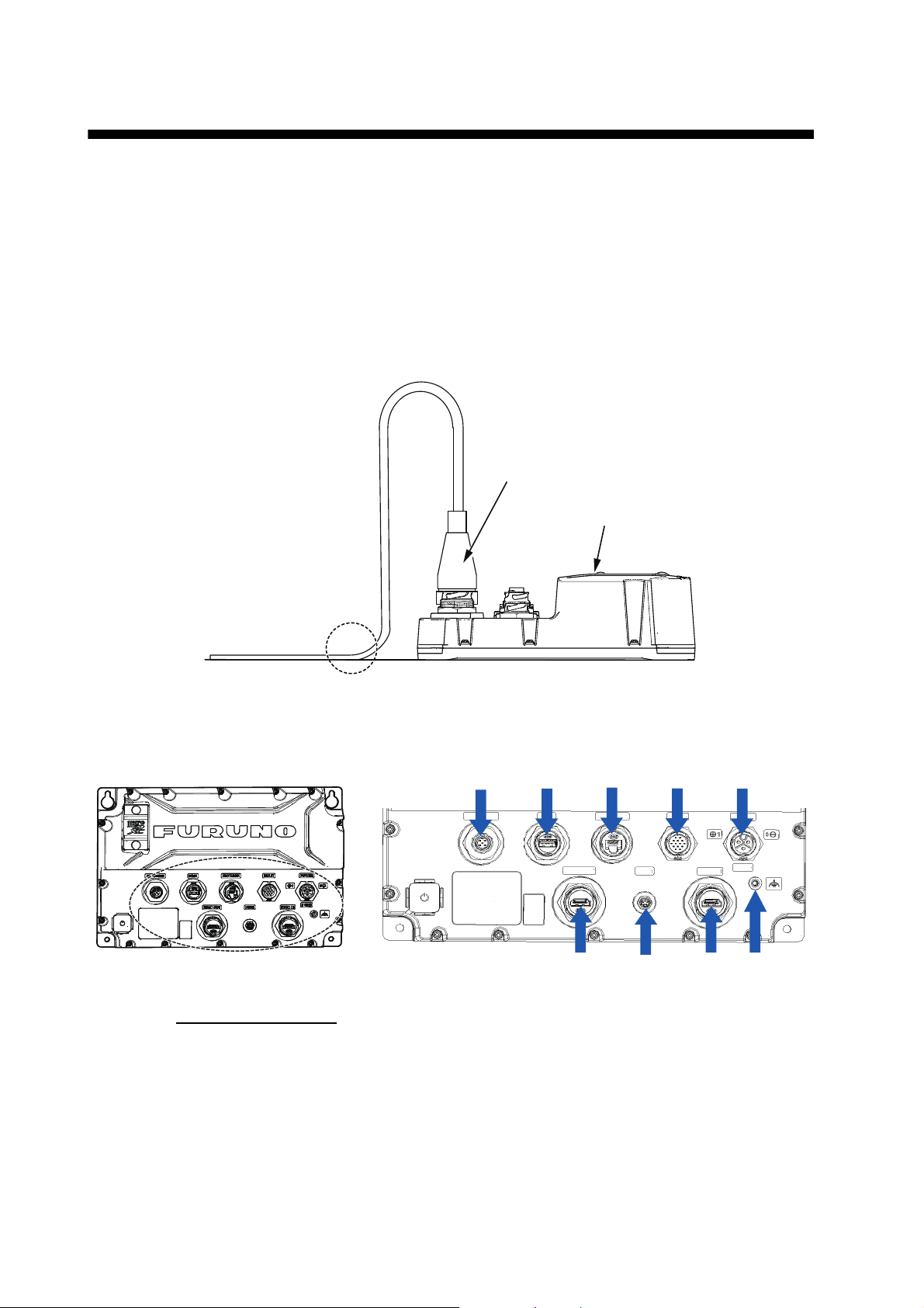
2.1 Precautions for Tabletop Mounting
When wiring on the tabletop mounting, be sure to secure the cable near the processor
unit so that there is no load on the connector due to vibration of the cable (see figure
below).
When connecting the power cable, be sure to also connect the grounding wire (see
section 2.2).
2.2 Interface Connections (rear of the unit)
Analog video input
The TZTBBX can use regular analog video inputs (PAL or NTSC) that
connect to the TZTBBX directly via the Video In connector on the optional MULTI cable (connected to the MULTI port). Analog video can be viewed only on the equipment
where the source is connected.
Additionally a single FLIR camera may be connected to the TZTBBX. Connect the Video Out cable from the camera to the Video In cable on the TZTBBX.
Note: Some camera models may require an adapter for connection.
3
Page 9
2. WIRING
Cameras may be set up using the appropriate menu item on the [Camera] menu,
accessed from the [Settings] menu. For details on camera setup, see the operator’s
manual (OME-45240-x)
Network
You can connect to an external network device using a LAN cable. Use HUB-101 or
HUB-102 (option) when connecting multiple devices. The MCU-005 can also be connected via a PoE hub.
Video out (external HDMI monitor)
The TZTBBX is compatible with wide-screen HDMI monitors which meet the following
minimum requirements:
Resolution Vert. Frequency Horiz. Frequency Pixel clock
1920 × 1080 60 Hz 67.5 kHz 148.5 MHz
1280 1024 64.0 kHz 108.0 MHz
1024 768 48.4 kHz 65.0 MHz
Video in (HDMI source devices)
Video data from HDMI source devices can be watched on TZTBBX by connecting the
device.
NMEA2000 (CAN bus) port
TZTBBX can be connected to multiple compatible NavNet TZT units using a micro
type NMEA 2000 connector. In that case, connect them all to the same network backbone cable (Refer to section 2.7 for details).
MULTI port
You can connect to external devices such as buzzers and event switches. Refer to
section 2.4 for details.
USB port
The TZTBBX has one USB Ver. 2.0 port ([USB 2] in figure on the page 3) and one
USB Ver. 3.0 ([USB 1] in figure on the page 3) port which can be used to connect a
remote control unit and/or to control a touch monitor.
2.3 Power Cable
Connect the power cable (FRU-PM03M-KCP01-RD, 2 m, supplied) to the connector.
When connecting the power supply, connect the positive and negative terminals correctly.
Note: Turn off the power at the switchboard before beginning the connection.
2.4 MULTI Cable
Use the optional MULTI cable to supply power to the NMEA 0183 instrument, the external buzzer, and the NMEA 2000. The connector has 14 wires and a connector
4
Page 10
2. WIRING
(SMP-11V). Use the table below for reference and connector (SMD-11V, local supply)
when connecting the MULTI cable.
Wire color Function Description
White NMEA-TD-B
Blue NMEA-TD-A
Gray BUZZER External buzzer ON/OFF
Red 12 V_OUT+ External buzzer power (12 V)
Orange EVENT_SW Event switch (MOB, etc.)
Black GND Grounding for +12V/EVENT_SW
Purple PWR_SW Power switch
Brown KPI 5-12 VDC, Positive
Red/White KPO 12 VDC, Positive
Black/White GND Grounding for KP
Brown/White GND Grounding for power switch
Braided (external) SHIELD FG
Signal Signal For video input (RCA Jack)
Braided (internal) GND For video signal
NMEA 0183 Output
2.4.1 How to set up NMEA 0183 data output
Note: To set up data input from NMEA 0183 equipment, see "NMEA 0183 equipment
data input" on page 2-7.
1. Tap the [FURUNO] icon ( ) to show the home screen.
2. Tap [Settings], then drag the menu to show [Initial Setup]. Tap [Initial Setup].
3. Tap [Data Sensors], then tap [NMEA0183 Output].
4. Tap [Baud Rate] to set the output baud rate. Available options are [4,800], [9,600]
and [38,400].
5. Tap the appropriate setting then tap the icon.
6. Tap [NMEA-0183 Version] to set the version. Available options are [1.5], [2.0] and
[3.0].
7. Tap the appropriate setting then tap the icon.
8. Select the sentences to output. Tap a sentence, then tap its flipswitch to set the
sentence to [ON].
9. Tap the [Close] icon at the top right of the screen to close the menus.
2.5 DRS Radar Sensor Connections
The figures below show connection examples with radar sensors which are compatible with the TZTBBX.
For details regarding connection and cables required for connection with the radar
sensor, see the radar sensor’s installation manual.
Note: DRS2D-NXT and DRS4D-NXT cannot be used in Japan.
DRS4D X-Class is for Japanese market only.
5
Page 11
2. WIRING
Connection examples for radome sensors
TZTBBX
To ship mains
(12 to 24 VDC)
HUB-101
Connection examples for open-array sensors
To ship mains
(12* to 24 VDC)
HUB-101
*: 12 VDC is only used
with DRS6A-NXT. All
other open array DRS
sensors require 24
VDC.
DRS6A X-Class/DRS12A X-Class/
DRS25A X-ClassDRS6A-NXT/
DRS12A-NXT/ DRS25A-NXT
DRS4D X-Class/DRS4DL+
DRS2D-NXT/DRS4D-NXT
TZTBBX
2.6 Network Connection with Other TZT Series Units
Your TZTBBX is equipped with a network connector (RJ45). Like previous NavNet series equipment, the TZTBBX is able to share Radar images and other information,
across an Ethernet connection. Up to six NavNet TZtouch units may be connected to
the same network at one time (see page iii for the details). However, for configurations
with one or more TZT2BB included, the maximum number of networked NavNet TZtouch units is four. For example, a configuration with one TZTBBX and one TZT12F
can have two TZT2BB units connected.
2.7 NMEA 2000 Connector
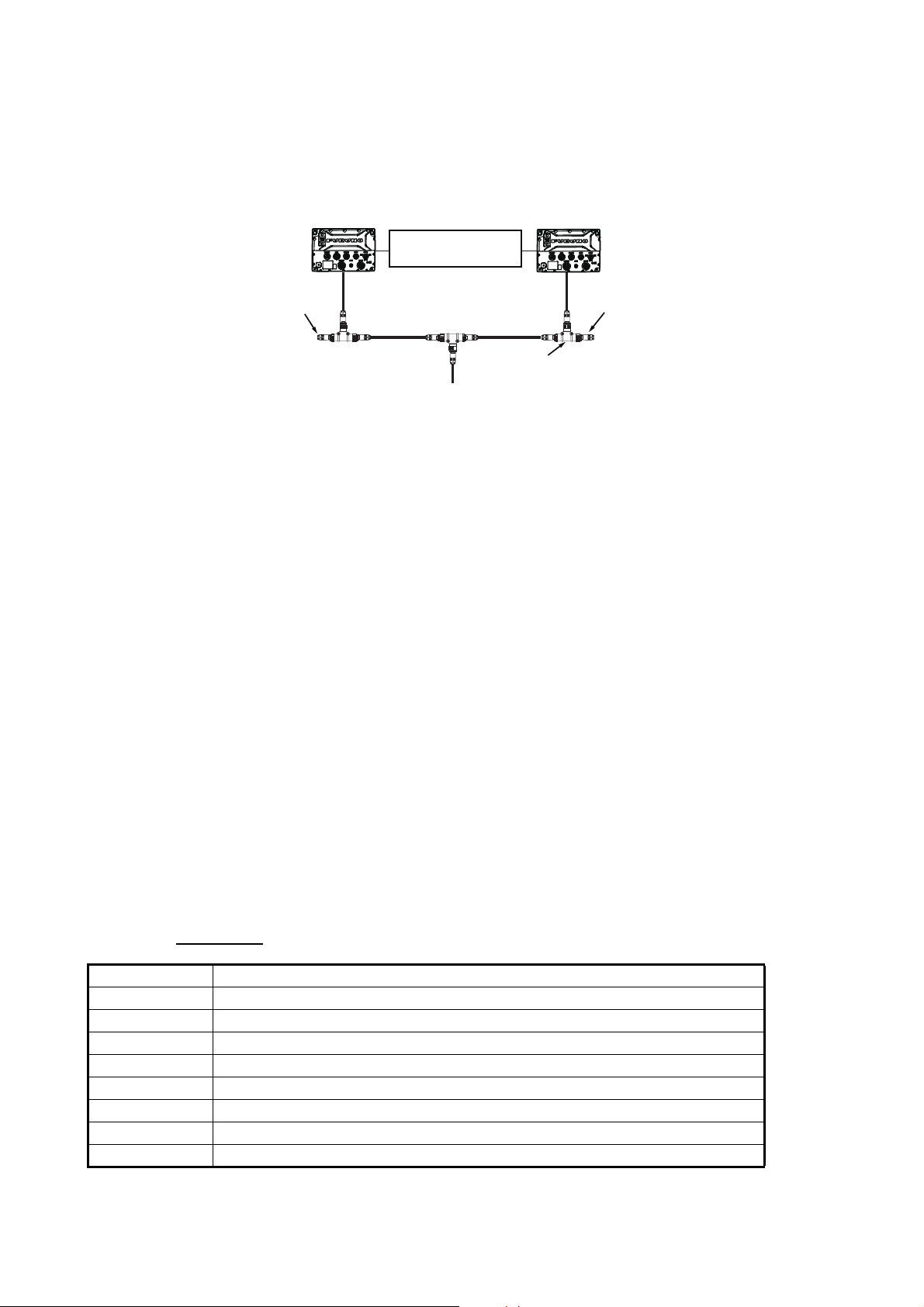
The TZTBBX has one NMEA 2000 connector (micro type connector). All TZTBBX
must be connected to the same NMEA 2000 backbone.
What is NMEA 2000?
NMEA 2000 (also knows as CAN bus) is a communication protocol that shares multiple data and signals through a single backbone cable. You can simply connect any
NMEA 2000 devices onto the backbone cable to expand your network on-board. With
NMEA 2000, IDs are assigned to all the devices in the network, and the status of each
sensor in the network can be detected. All the NMEA 2000 devices can be incorporated into the NMEA 2000 network. For detailed information about NMEA 2000 wiring,
see "FURUNO CAN bus Network Design Guide" (Type: TIE-00170).
6
Page 12
2. WIRING
NMEA2000 backbone
To ship-board power
T-connector
2.7.1 How to connect the NavNet TZtouchXL to NMEA 2000 equipment
Below is an example of two units, connected to NMEA 2000 sensors via the network.
NavNet
TZtouchXL
Ethernet connection
via HUB-101
Terminator
NMEA2000 backbone
T-connector
To ship-board power
Note 1: The NMEA 2000 network requires a dedicated NMEA 2000 power supply.
Turn the NMEA 2000 network power on before turning your connected equipment on.
Note 2: Terminators must be installed at both ends of the NMEA 2000 backbone cable. See the "EQUIPMENT LISTS" on page iv for available terminators.
2.7.2 NMEA 0183 equipment data input
Note: To output NMEA 0183 data, see section 2.4.1.
To connect NMEA 0183 equipment to TZTBBX, use the NMEA 2000 network via the
optional NMEA data converter IF-NMEA2K2 (or IF-NMEA2K1). This NMEA
connection can accept a baud rate of 4800 or 38400.
NavNet
TZtouchXL
Terminator
Heading input to TZTBBX allows functions such as Radar Overlay and course stabilization (North up, etc.) in the radar operating modes. The NMEA 0183 heading refresh
rate needs to be 100 ms in order for any radar function to work properly. NMEA 0183
heading can be accepted on any NMEA 2000 port at a baud rate up to 38400 bps.
Note 1: When using the ARPA function, set the heading refresh rate to 100 ms.
Note 2: For more information on connecting and wiring IF-NMEA2K2, refer to their re-
spective installation manuals.
2.7.3 NMEA 2000 input/output
Input PGN
PGN Description
059392 ISO Acknowledgment
059904 ISO Request
060160 ISO Transport Protocol, Data Transfer
060416 ISO Transport Protocol, Connection Management - BAM group function
060928 ISO Address Claim
061184 Self Test Group Function (Proprietary PGN)
065240 ISO Commanded Address
065280 Heave (Proprietary PGN)
7
Page 13

PGN Description
NMEA-Request Group Function
126208
126464 PGN List - Transmit PGN’s group function
126720 Memory Clear Group Function (Proprietary PGN)
126992 System Time
126996 Product Information
126998 Configuration Information
127237 Heading/Track Control
127245 Rudder
127250 Vessel Heading
127251 Rate of Turn
127252 Heave
127257 Attitude
127258 Magnetic Variation
127488 Engine Parameters, Rapid Update
127489 Engine Parameters, Dynamic
127493 Transmission Parameters, Dynamic
127498 Engine Parameters, Static
127503 AC Input Status
127505 Fluid Level
127506 DC Detailed Status
127508 Battery Status
128259 Speed
128267 Water Depth
129025 Position, Rapid Update
129026 COG &SOG, Rapid Update
129029 GNSS Position Data
129033 Local Time Offset
129038 AIS Class A Position Report
129039 AIS Class B Position Report
129040 AIS Class B Extended Position Report
129041 AIS Aids to Navigation (AtoN) Report
129291 Set &Drift, Rapid Update
129538 GNSS Control Status
129540 GNSS Satellites in View
129793 AIS UTC and Date Report
129794 AIS Class A Static and Voyage Related Data
129795 AIS Addressed Binary Message
129797 AIS Binary Broadcast Message
129798 AIS SAR Aircraft Position Report
129801 AIS Addressed Safety Related Message
129802 AIS Safety Related Broadcast Message
129808 DSC Call Information
129809 AIS Class B "CS" Static Data Report, Part A
129810 AIS Class B "CS" Static Data Report, Part B
130306 Wind Data
130310 Environmental Parameters
130311 Environmental Parameters
NMEA-Command Group Function
NMEA-Acknowledge Group Function
2. WIRING
8
Page 14
2. WIRING
PGN Description
130312 Temperature
130313 Humidity
130314 Actual Pressure
130316 Temperature, Extended Range
130576 Trim Tab Status
130577 Direction Data
130578 Vessel Speed Component
130817 Furuno GNSS Control Status (Proprietary PGN)
130818 Heading & Attitude Sensor Control Status (Proprietary PGN)
130820 Motion Sensor Status(Proprietary PGN)
130822 130822 Unit Division Code(Proprietary PGN)
130823 Browser Control Status(Proprietary PGN)
130826 Multi Sats In View (Proprietary PGN)
130827 NAVpilot General Message (Proprietary PGN)
130828 Mark Position Information(Proprietary PGN)
130845 Multi Sats in View Extended (Proprietary PGN)
130846 Motion Sensor Status Extended (Proprietary PGN)
130848 Water Current Layer (Proprietary PGN)
130880 Additional Weather Data(Proprietary PGN)
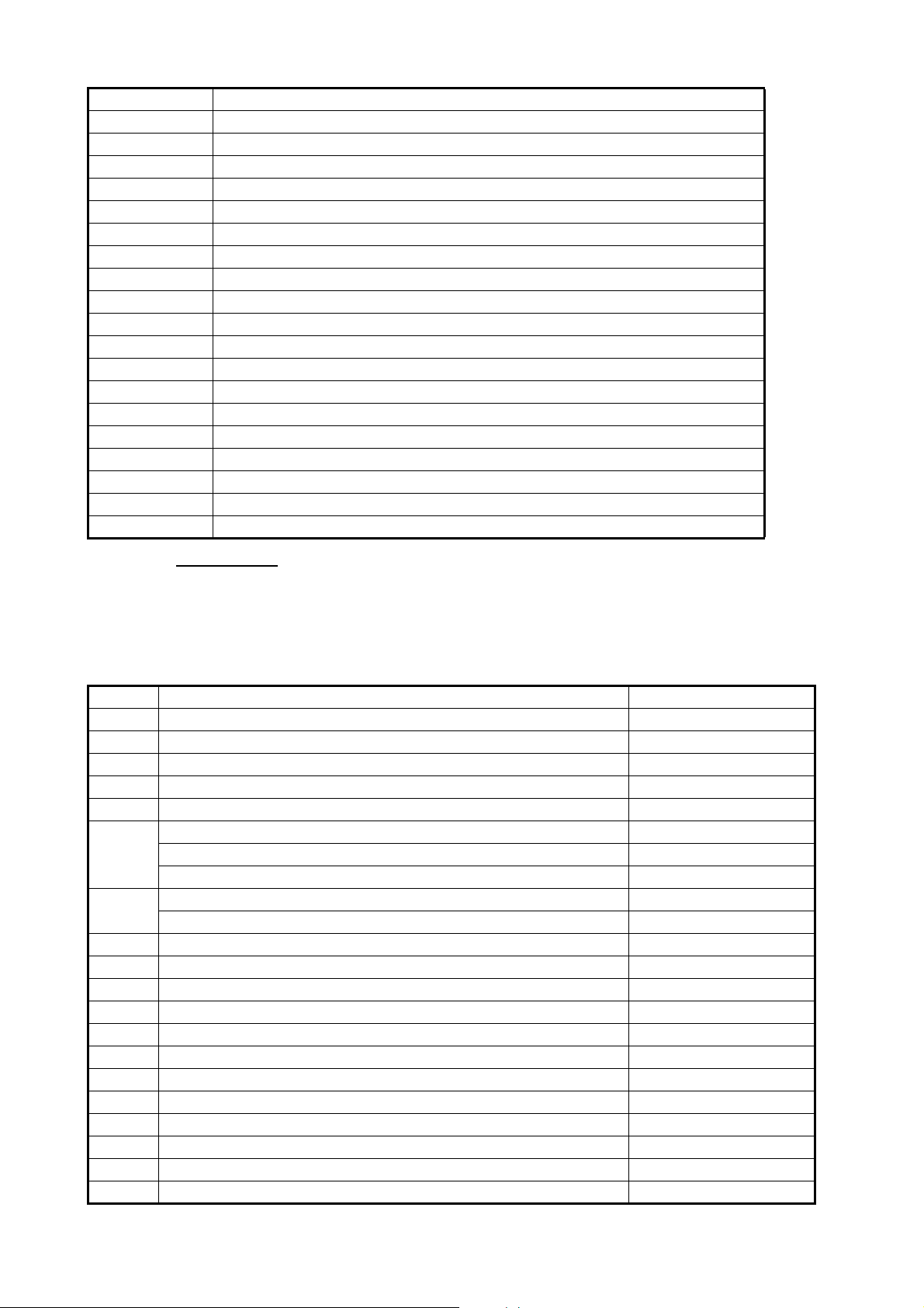
Output PGN
The NMEA 2000 output PGN setting (found under the [Initial Setup] menu) is global to
the network. Note that only one TZTBBX will output NMEA 2000 data on the network
at a time: the TZTBBX which is powered ON first. If that display is turned OFF, another
will take its place to output the data.
PGN Description Output cycle (msec)
059392 ISO Acknowledgement
059904 ISO Request
060928 ISO Address Claim
061184 Self Test Group Function (Proprietary PGN)
065287 HID Target Status (Proprietary PGN)
126208 NMEA-Request group function
NMEA-Command group function
NMEA-Acknowledge group function
126464 PGN List-Transmit PGN’s group function
PGN List-Received PGN’s group Function
126720 Memory Clear Group Function (Proprietary PGN)
126992 System Time 1000
126993 Heartbeat
126996 Product Information
126998 Configuration Information
127250 Vessel Heading 100
127251 Rate of Turn 100
127257 Attitude 1000
127258 Magnetic Variation 1000
128259 Speed 1000
128267 Water Depth 1000
128275 Distance Log 1000
9
Page 15
2. WIRING
GPS RECEIVER
GP-330B
*
2
12 to 24 VDC
12 to 24 VDC
12 to
24 VDC
12 to 24
VDC
*
1
: The HUB-101 is required when two or more
pieces of network equipment are connected
to the TZTBBX.
*
2
: Backup
HUB-101*
1
OR
NMEA 2000 backbone cable
NMEA 2000
drop cable
NMEA 2000
drop cable
Optional LAN cable
FRU-RZWPNWP,
2 m, 3 m, 5 m, 10 m
Cable Assy.
FRU-2P5S-FF
NMEA 2000
drop cable
12*3 to 24 VDC
*3: 12 VDC is only used with DRS6A-NXT.
All other open array DRS sensors require 24 VDC.
Radar Sensor
DRS6A X-Class/DRS12A X-Class/
DRS25A X-Class/
DRS6A-NXT/
DRS12A-NXT/DRS25A-NXT
Radar Sensor
DRS4D X-Class/DRS4DL+/
DRS2D-NXT/DRS4D-NXT
TZTBBX
TZTBBX
Cable Assy.
FRU-2P5S-FF
PGN Description Output cycle (msec)
129025 Position, Rapid Update 100
129026 COG & SOG, Rapid Update 250
129029 GNSS Position Data 1000
129033 Local Time Offset 1000
129283 Cross Track Error 1000
129284 Navigation Data 1000
129285 Navigation-Route/WP information
130306 Wind data 100
130310 Environmental Parameters 500
130312 Temperature 2000
130313 Humidity 2000
130314 Actual Pressure 2000
130316 Temp., Extended Range 2000
130821 NAV Source Select (Proprietary PGN)
130822 Unit Division Code (Proprietary PGN)
130823 Browser Control Status (Proprietary PGN)
130827 NAVpilot General Message (Proprietary PGN)
130841 N2K System Setup Information (Proprietary PGN)
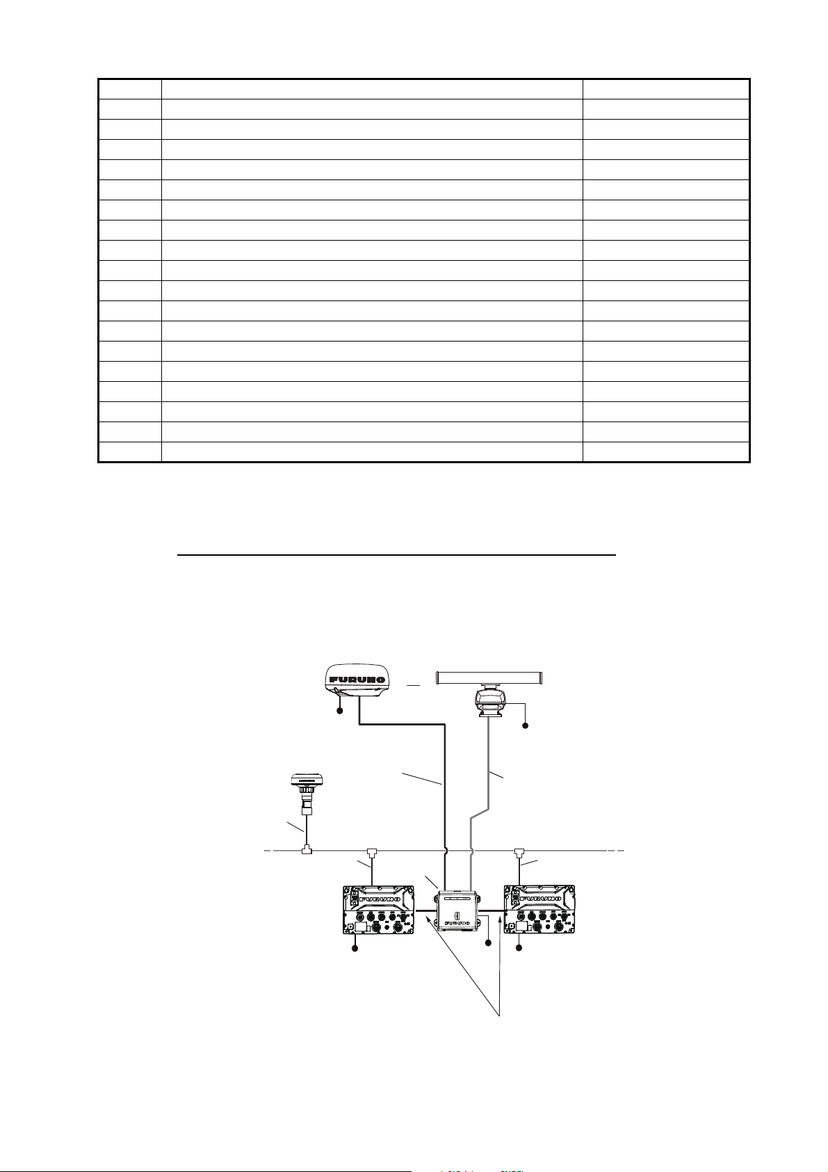
2.8 Example TZTBBX System Configuration
Mid/Large-size vessels (External GPS, Fish Finder, Radar)
This is a sample of the chart plotter/radar/fish finder installation. Refer to "SYSTEM
CONFIGURATION" on page ii for more details.
10
Page 16
3. HOW TO SET UP THE EQUIP-
Home menu
D
i
s
pl
a
y
Mo
de
Se
tt
i
ng
s
Display Mode SettingsDisplay Mode Settings
TZTBBX
MENT
This chapter shows you how to set up your system according to the equipment you
have connected.
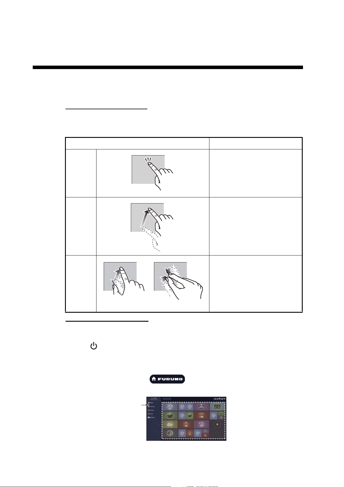
Touch control description
The touch control depends on the screen type. The basic operations to use during the
installation setup are in the following table.
Operating by a finger Function
Tap • Select a menu item.
• Select a setting option where
there are multiple options.
• Select an object.
• Display the pop-up menu
where available.
Drag • Scroll the menu.
Pinch Change the fish finder, plotter
and radar range.
Zoom in Zoom out
How to operate the menus
The following procedure shows how to use the menu system.
1. Tap (power switch) to turn the power on.
2. After the startup process completes, the last used display appears and a warning
message is displayed. Read the message, then tap [OK].
3. Tap the [FURUNO] icon ( ) to show the home screen and display
mode settings.
4. Tap [Settings] to open the [Settings] menu.
11
Page 17
3. HOW TO SET UP THE EQUIPMENT
Menu title
Close icon
Back icon
Menu
items
Menu
items
Preview screen
Changes made in the
menu can be
previewed here
Preview screen
Changes made in the
menu can be
previewed here
ON
OFF
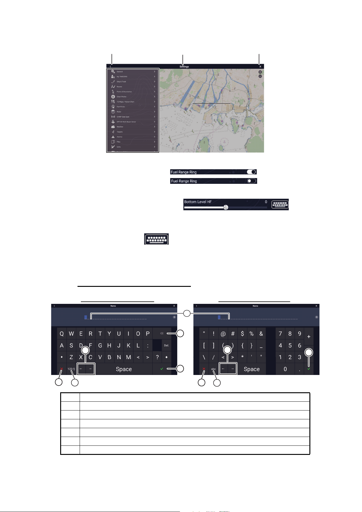
5. Drag the menu to show [Initial Setup], then tap [Initial Setup].
6. Depending on the menu item selected, the following operations are available:
• ON/OFF flipswitch.
Tap to switch between [ON] and [OFF] to activate or deactivate the function.
• Slidebar and keyboard icon.
Drag the slidebar to adjust the setting. Settings may also be adjusted using the
software keyboard for direct input.
• Keyboard icon.
Referring to the figure on the following page, use the software keyboard to input
alphabet or numeric characters.
7. Tap [Close] (Indicated as an "X") at the top right-hand side of the screen to exit.
How to use the software keyboard
Alphabet software keyboard Numeric software keyboard
1
2
4
3
5
6
5
4
6
3
No. Description
1 Cursor position is highlighted.
2 Backspace/Delete. Tap to erase one character at a time.
3 Enter button. Tap to complete character input and apply changes.
4 Cursor keys. Tap to move the cursor left/right.
5 Cancel button. Aborts character entry. No changes are applied.
6 Tap to switch between alphabet and numeric keyboards (where available).
12
Page 18
3. HOW TO SET UP THE EQUIPMENT
3.1 How to Set Time Zone, Time Format and Language
Before setting up your equipment, select the time zone, language and units to use on
your equipment as shown below.
1. Tap the [FURUNO] icon ( ) to show the home screen and display
mode settings.
2. Tap [Settings] to show the [Settings] menu.
3. Tap [General] to show the [General] menu.
4. Tap [Local Time Offset] to show the numerical keyboard.
5. Input the time difference (using 15-minute intervals) between local and UTC , then
tap [].
6. Drag the menu to show the [Time Format] menu item, then tap [Time Format] to
show the option window.
7. Select how to display time, in 12- or 24-hour format. [Auto] automatically inserts
AM, PM indication in 24 hour clock, when the language is English.
8. Tap the [<] at the top left of the screen to return to the [General] menu.
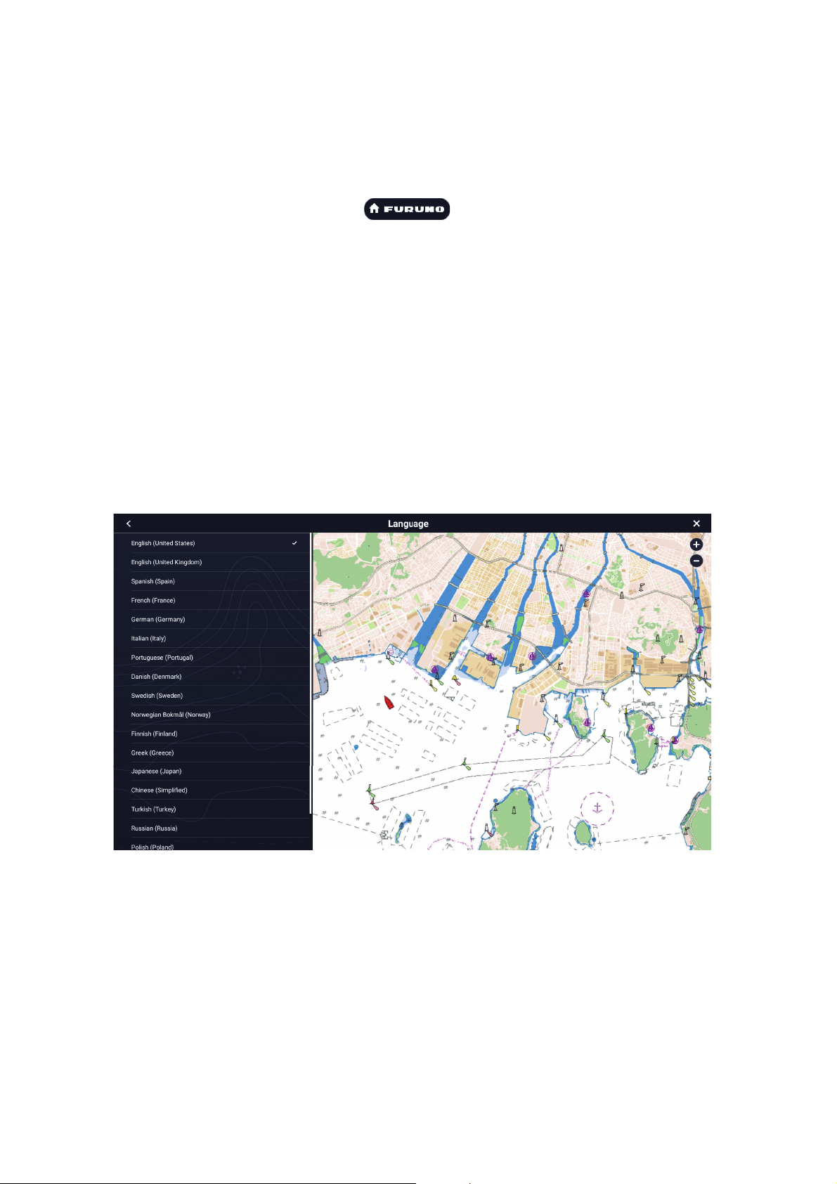
9. Tap [Language] to show the [Language] menu.
10. Tap the appropriate language to use. The unit will display a confirmation mes-
sage. Tap [OK] to restart the unit and apply the new language settings.This process takes approximately five minutes to optimize the system for the new
language setting. When the process is completed (five minutes later), the system
restarts automatically.
13
Page 19
3. HOW TO SET UP THE EQUIPMENT
3.2 How to Set Units of Measurement
1. Tap the [FURUNO] icon ( ) to show the home screen and display
mode settings.
2. Tap [Settings] to show the [Settings] menu.
3. Drag the main menu to display [Units], then tap [Units].
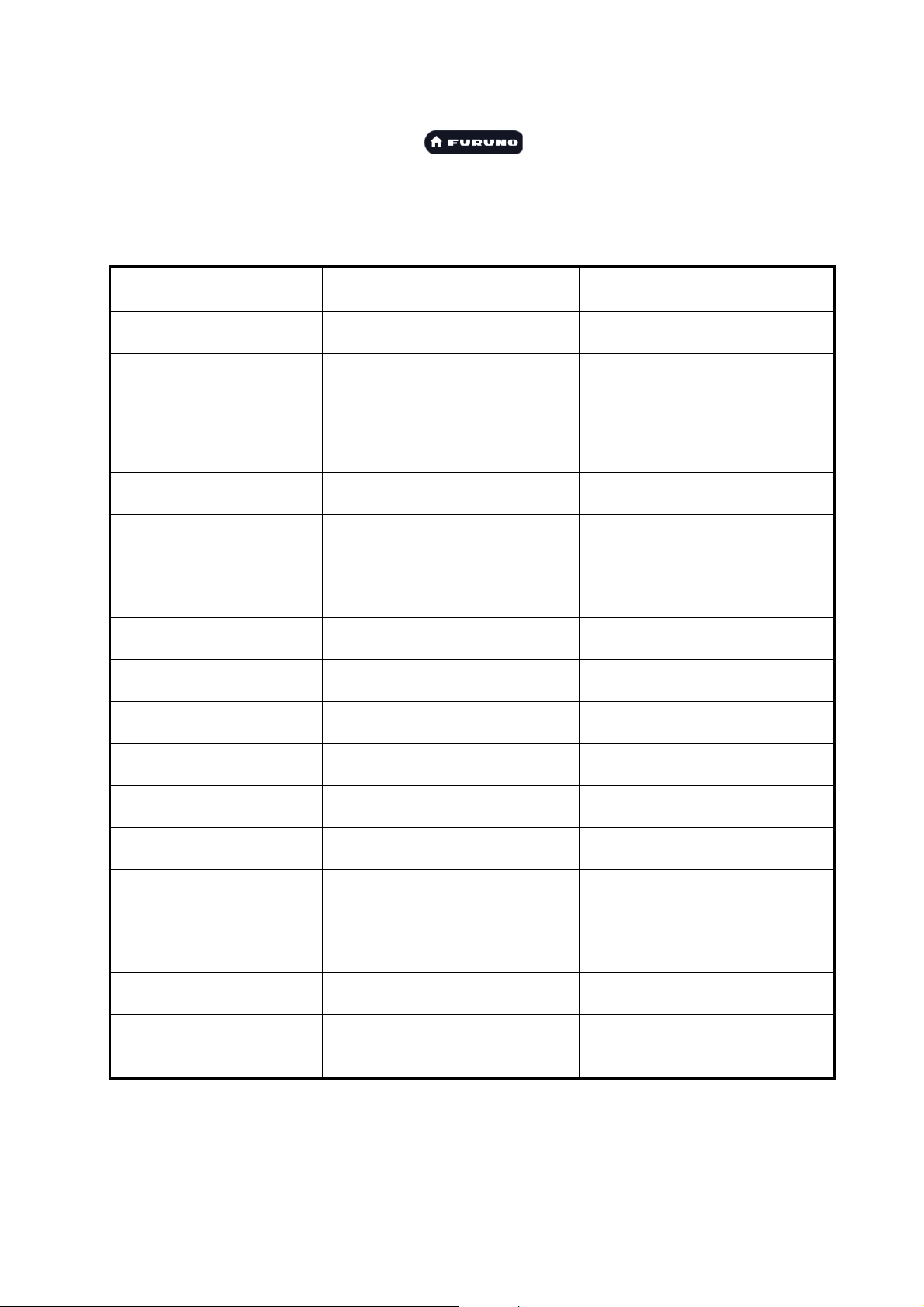
4. Referring to the table below, set the units to show on the display.
Menu item Description Options
[Bearing Display] Adjust the bearing display format. [Magnetic], [True]
[True Wind Calculation
Reference]
[Position Format] Set the display format for position
[Loran C Station &GRI] Available when [Position Format]
[Short/Long Change Over] Set the distance at which to
[Range (Long)] Set the unit of measurement for
[Range (Short)] Set the unit of measurement for
[Depth] Set the unit of measurement for
[Height/Length] Set the unit of measurement for
[Fish Size] Set the unit of measurement for
[Temperature] Set the unit of measurement for
[Boat Speed] Set the unit of measurement for
[Wind Speed] Set the unit of measurement for
[Atmospheric Pressure] Set the unit of measurement for
[Oil Pressure] Set the unit of measurement for
[Volume] Set the unit of measurement for
[Reset Default Settings] Restore default unit settings. [OK], [Cancel]
Set the reference for calculating
true wind speed/angle.
(Latitude/Longitude).
is selected to [Loran-C].
change between short and long
range.
long distances.
short distances.
depth.
height and length.
fish sizes.
temperature.
boat speed.
wind speed.
atmospheric pressure.
oil pressure.
tank volume.
[Ground], [Surface]
[DDD°MM.mmmm’],
[DDD°MM.mmm’],
[DDD°MM.mm’],
[DDD°MM’SS.ss"],
[DDD.dddddd°],
[Loran-C], [MGRS]
Set Loran C station and GRI combination.
[0.0] to [2.0] (NM)
[Nautical Mile], [Kilometer], [Mile]
[Foot], [Meter], [Yard]
[Foot], [Meter], [Fathom], [Passi
Braza]
[Foot], [Meter]
[Inch], [Centimeter]
[Fahrenheit Degree], [Celsius
Degree]
[Knot], [Kilometer per Hour], [Mile
per Hour], [Meter per Second]
[Knot], [Kilometer per Hour], [Mile
per Hour], [Meter per Second]
[HectoPascal], [Millibar],
[Millimeter of Mercury], [Inch of
Mercury]
[KiloPascal], [Bar], [Pound per
Square Inch]
[Gallon] (Gallon &Gallon/hour),
[Litre] (Litre &Litre/hour)
14
Page 20
3. HOW TO SET UP THE EQUIPMENT
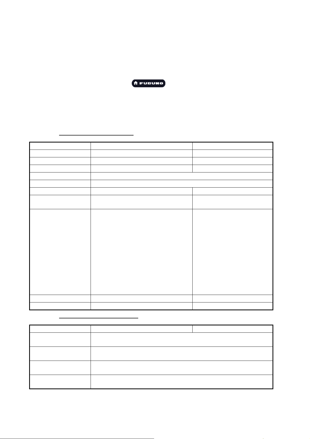
3.3 Initial Setup
This section shows you how to set your system according to the sensors you have
connected.
Note: Some units are set to metric in this section, actual setting ranges vary
depending on the unit of measurement set in the [Units] menu.
1. Tap the FURUNO icon ( ) to show the home screen and display
mode settings.
2. Tap [Settings] to show the [Settings] menu.
3. Drag the main menu, then tap [Initial Setup] to show the [Initial Setup] menu.
4. Referring to the tables on the following pages, set your equipment.
[Boat Information] section
Menu item Description Options (setting range)
[Boat Height] Set the height of your boat. 0 (m) to 999 (m)
[Boat Width] Set the width of your boat. 0 (m) to 999 (m)
[Boat Length] Set the length of your boat. 0 (m) to 999 (m)
[Boat MMSI] Set the MMSI for your boat (used for fleet tracking function only).
[Boat Name] Set the name for your boat (used for fleet tracking function only).
[Size of Own Ship Icon] Set the size of own ship icon. 50 to 150
[Depth Display] Select the start point for depth measure-
ment.
[External Transducer
Draft]
[Keel Draft] Set the keel draft. 0.0 (m) to 99.9 (m
[Engine Count] Set the number of engines. 0 to 6
Set the draft for external transducers
other than internal fish finder, networked
or multi-beam sonar.
For internal/network transducers, set
the draft from Home
screen→[Settings]→[Fish
Finder]→[Fish Finder Initial
Setup]→[Transducer Draft].
For multi-beam sonars, set the draft
from Home
screen→[Settings]→[Multibeam
Sonar]→[Initial Setup]→[Transducer
Draft].
[Under Keel],
[Under Sea Level]
0.0 (m) to 99.9 (m)
[Instruments Setup] section
Menu item Description Options (setting range)
[Engine &Tank Automatic Setup]
[Engine &Tank Manual
Setup]
[Graphic Instruments
Setup]
[Reset Default Page
Settings]
See "[Engine &Tank Automatic Setup] section" on page 3-20.
See "[Engine &Tank Manual Setup] section" on page 3-20.
See "[Graphic Instruments Setup] section" on page 3-19.
Resets [Instruments Setup] menu settings to default.
15
Page 21
3. HOW TO SET UP THE EQUIPMENT
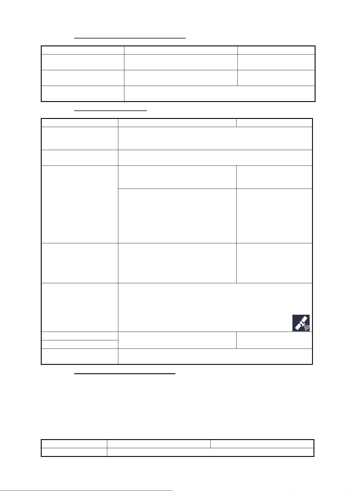
[Manual Fuel Management] section
Menu item Description Options (setting range)
[Total Fuel Capacity] Enter the total fuel capacity of your
tank(s).
[Manual Fuel Management] Set to [ON] for manual fuel manage-
ment. See the Operator’s Manual.
[Reset Default Page
Settings]
Resets [Manual Fuel Management] menu settings to default.
0 to 9,999(L).
Off, On
[Data Sensors] section
Menu Item Description Options (setting range)
[Data Sources] Select the source for each data to input to the system. If two or more
sources are connected for a data, select one using the pull-down dialog
box. The FURUNO products are shown at the upper part of the list.
[Sensor List] Show the information for sensors connected to your equipment. Also,
you can set "Nickname" for them here.
[NMEA0183 Output] • [Baud Rate]: Select the baud rate.
• [NMEA-0183 Version]: Select the version for NMEA 0183.
[Sentences]: Select the sentences to output.
Note: If the TTM sentence is received at
the same time as another sentence, the
constraints to communication bandwidth
may cause a decrease in the number of
TTM targets.
• [4,800], [9,600],
[38,400]
• [1.5], [2.0], [3.0]
Off, On
[NMEA2000 PGN Output] Turn On for the PGN's (Parameter Group
Number, NMEA 2000 message) to output
from the NMEA 2000 port.
Note: The default setting of some PGNs is
“On”.
[Sky View…] Show the condition of GPS and GEO (WAAS) satellites on the [GPSS-
kyView] display. The bearing and elevation angle of all GPS and GEOsatellites (if applicable) in view of your receiver appear. For the service
technician.
Note: The [GPS SkyView] display can also be shown by tappingthe GPS icon (shown right) on the Home page.
[GP330B WAAS Mode] Turn On to use the WAAS mode for the
[WS200 WAAS Mode]
[Reset Default Page
Settings]
corresponding GPS antenna.
Resets [Data Sensors] menu settings to default.
Off, On
Off, On
[Network Sensor Setup] section
The [NETWORK SENSOR SETUP] section allows you to set up compatible FURUNO
NMEA 2000 sensors. Calibrations and offsets applied in this menu are also applied to
the sensor itself.
Tap the sensor to access its menus and settings. For details regarding the menu structure and set up of each sensor, see the appropriate operator’s manual, supplied with
the sensor.
Menu item Description Option (setting range)
[FAX-30 Browser] Show the Facsimile Receiver FAX-30 display.
16
Page 22
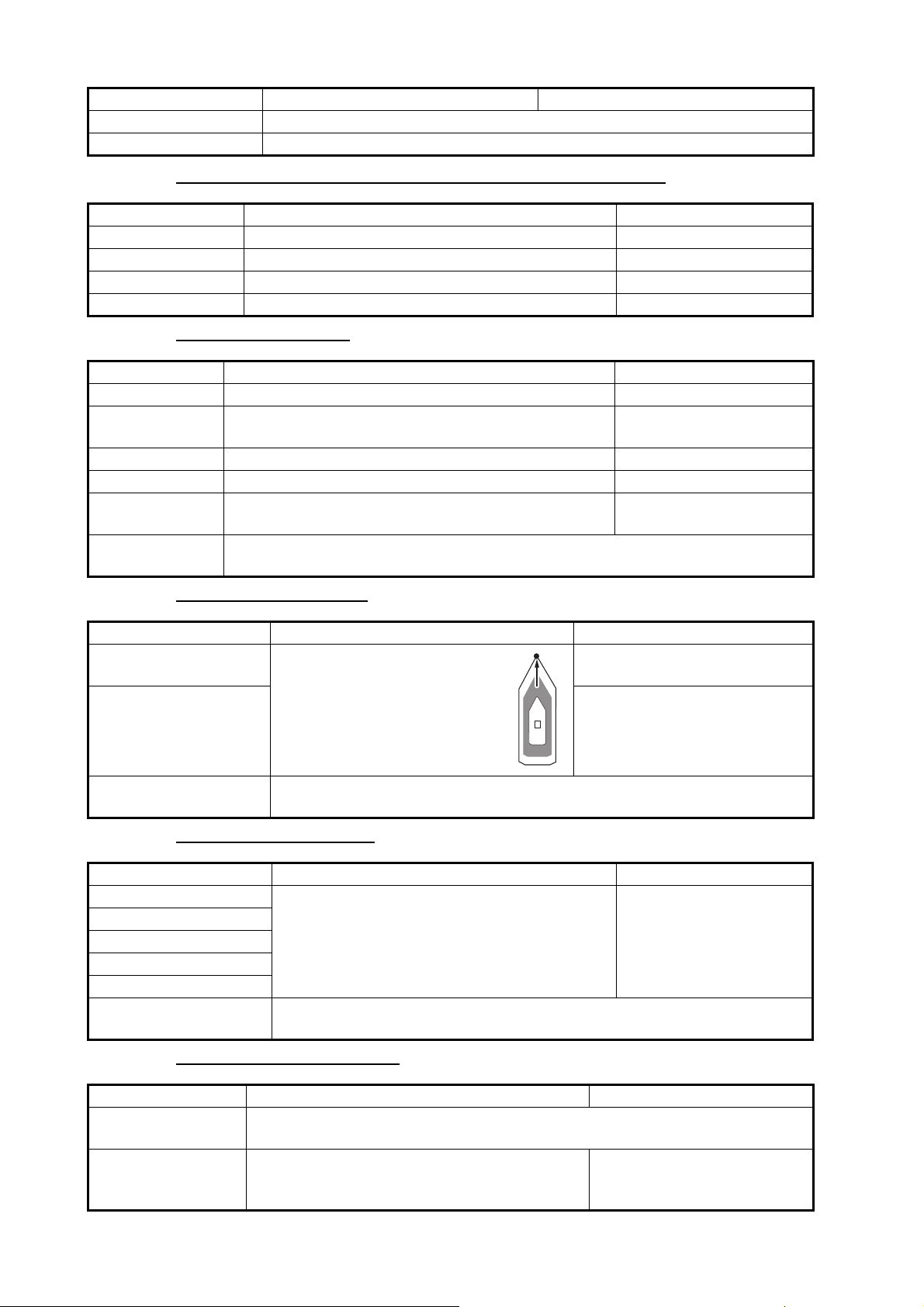
3. HOW TO SET UP THE EQUIPMENT
OriginOrigin
Menu item Description Option (setting range)
[FA-30 Browser] Show the AIS Receiver FA-30 display.
[FA-50 Browser] Show the AIS Receiver FA-50 display.
[SC-30 Setup] section (only when the SC-30 is connected)
Menu item Description Options (setting range)
[WAAS Mode] Turn On to use the WAAS mode. Off, On
[Heading Offset] Enter the offset value for heading. -180° to +180°
[Pitch Offset] Enter the offset value for pitching. -90° to +90°
[Roll Offset] Enter the offset value for rolling. -90° to +90°
[Data Offset] section
Menu item Description Options (setting range)
[Heading] Offset heading data. -180.0° to +180.0°
[Speed Through
Water]
[Wind Speed] Offset wind speed data. Enter amount in percentage. -50% to +50%
[Wind Angle] Offset wind angle data. -180° to +180°
[Sea Surface
Temperature]
[Reset Default
Page Settings]
Calibrate speed data. Enter amount in percentage. -50% to +50%
Offset sea surface temperature data. -10°C to +10°C
Resets [Data Offset] menu settings to default.
[GPS Position] section
Menu item Description Options (setting range)
[Longitudinal (from
bow]
[Lateral (-Port)] -99 (m) to +99 (m)
[Reset Default Page
Settings]
Referring to the figure on the
right, enter the GPS antenna
positioning bow-stern
(Longitudinal) and
port-starboard (Lateral)
position from the origin.
Resets [GPS Position] menu settings to default.
0 (m) to 999 (m)
Port-side is negative,
Starboard-side is positive.
[Data Damping] section
Menu item Description Options (setting range)
[COG & SOG] Set data damping time. The lower the setting
[Heading]
[Speed Through Water]
[Wind Speed & Angle]
[Rate of Turn]
[Reset Default Page
Settings]
the faster the response to change.
Resets [Data Damping] menu settings to default.
0 to 59 seconds
[IF-NMEAFI Setup] section
Menu item Description Options (setting range)
[Select IF] Select [IF-NMEAFI] to set the analog data that is input from the IF-NMEAFI.
The setting is made after restarting the IF-NMEAFI.
[Category] Select the use (category) for this sensor. [Wind], [ST800_850], [Fuel],
[FreshWater], [WasteWater],
[LiveWell], [Oil], [BlackWater]
17
Page 23
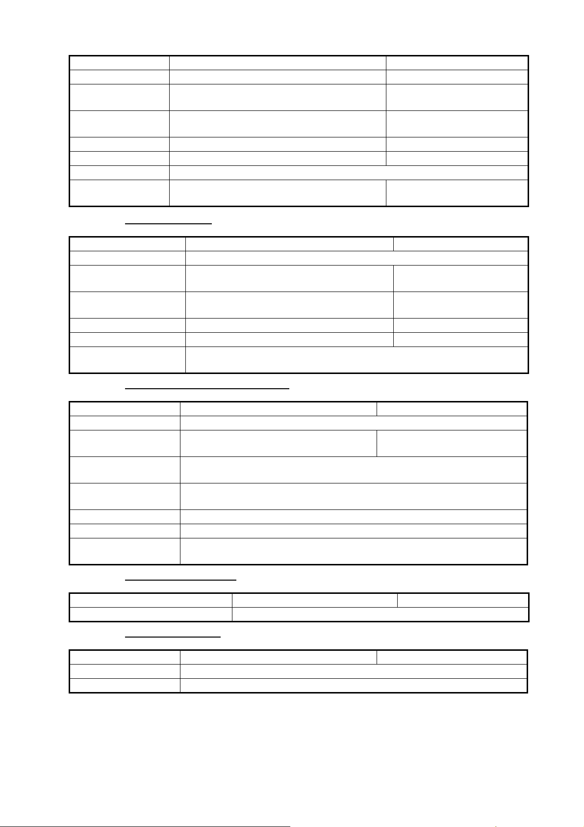
3. HOW TO SET UP THE EQUIPMENT
Menu item Description Options (setting range)
[Resistance Full] The resistance, in Ohms, when the tank is full. 0 (ohm) to 500 (ohm)
[Resistance Mid] The resistance, in Ohms, when the tank is half
full.
[Resistance Empty] The resistance, in Ohms, when the tank is
empty.
[Capacity] The capacity of the tank. 0 (G) to 2650 (G)
[Fluid Instance] Select the NMEA instance for the tank. 000 to 254
[Self test] Test results are displayed.
[Set Hardware to
Factory Default]
Resets the converter selected at
[Select IF] to factory default.
0 (ohm) to 500 (ohm)
0 (ohm) to 500 (ohm)
[OK], [Cancel]
[Fusion] section
Menu item Description Options (setting range)
[Connect to Fusion] Connects to your Fusion equipment.
[Fusion Auto Volume] Set to [On] to allow the TZTBBX unit to con-
trol the FUSION volume automatically.
[Minimum Speed] Set the minimum speed threshold. Exceed-
ing this speed activates volume auto control.
[Maximum Speed] Set the maximum speed threshold. 0.1 (kn) to 99.0 (kn)
[Volume Increase] Set the amount of extra volume to output . 10% to 50%
[Reset Default Page
Settings]
Resets [Fusion] menu settings to default.
Off, On
0.0 (kn) to 98.9 (kn)
[Service/Self Test/Log] section
Menu item Description Option (setting range)
[Synchronization Log] Shows synchronization with devices connected to the network.
[Enable NMEA2000
Log]
[NMEA2000 Log Stor-
age Location]
[Quick Self Test] Displays various details regarding the TZT10X/13X unit, radar and fish find-
[Certification Mark] Displays relevant certification for this equipment.
[Service] Requires login password. For the service technician.
[Reset Default Page
Settings]
Turn On when using NMEA 2000 log. Off, On
Show the location where to store the log.
er.
Resets [Service/Self Test/Log] menu settings to default.
[Home Page] section
Menu item Description Options (setting range)
[Factory Reset] Click [OK] to restore the [HOME] screen’s default settings.
Other menu items
Menu item Description Option (setting range)
[Chart Master Device] Turn On to use this unit as the master, Off to use this unit as a slave.
[System ID] The system ID for this device within the network.
18
Page 24
3. HOW TO SET UP THE EQUIPMENT
Menu item Description Option (setting range)
[Event Input
Configuration]
[Update Network
Equipments]
[Remote Controller
Configuration]
[Sirius Radio
Diagnostic]
[Sirius Weather
Diagnostic]
[Reset Default
Settings]
Set the function for the event switch.
• [Off]: Turns off the event switch function.
• [Event Mark]: Inputs an event mark at
the current position.
• [MOB]: Inputs the MOB at the current
position.
• [Ferry mode (bow azimuth reversal)]:
Turns ferry mode on or off.
For the service technician.
When there are multiple units in the NavNet network, the Remote Control
Unit MCU-004/-005/-006 can select the display to show on the unit with
MCU-004/-005/-006 connection. Further, the cycling order of displays can
be set. See the Operator’s Manual.
Check the satellite radio of the FURUNO BBWX SiriusXM weather receiver
for proper operation. See the Operator’s Manual.
Check the weather section of the FURUNO BBWX SiriusXM weather receiver for proper operation. See the Operator’s Manual.
Reset the system to default settings. [OK], [Cancel]
[OFF], [Event Mark], [MOB],
[Ferry]
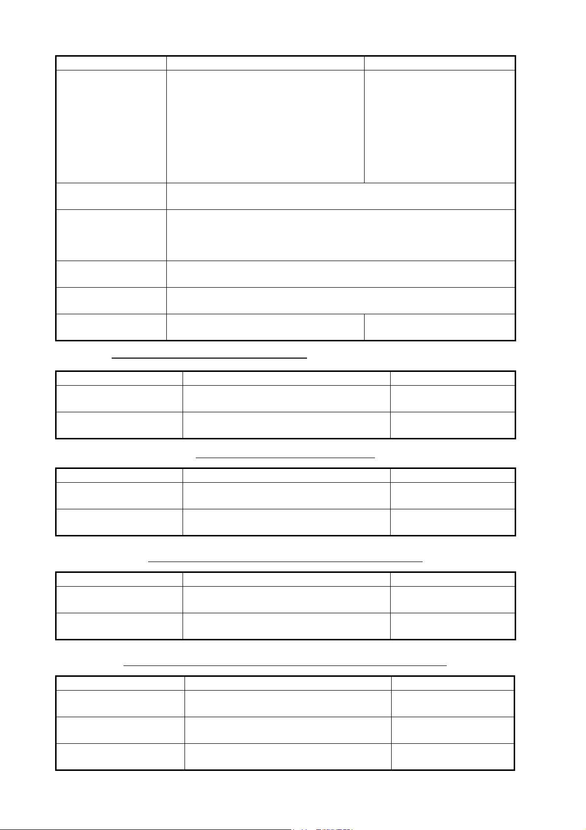
[Graphic Instruments Setup] section
Menu Item Description Options (setting range)
[Maximum Boat Speed] Set the transducer’s maximum detectable
speed.
[Maximum Wind Speed] Set the transducer’s maximum detectable
speed.
[Graphic Instruments Setup] - [Depth]
Menu Item Description Options (setting range)
[Minimum Depth] Set the transducer’s minimum detectable
depth.
[Maximum Depth] Set the transducer’s maximum detectable
depth.
[Graphic Instruments Setup] - [Sea Surface Temperature]
Menu Item Description Options (setting range)
[Minimum Sea Surface
Temperature]
[Maximum Sea Surface
Temperature]
Set the transducer’s minimum detectable
temperature.
Set the transducer’s maximum detectable
temperature.
1 (kn) to 99 (kn)
1 (kn) to 99 (kn)
1 (m) to 1999 (m)
1 (m) to 2000 (m)
0.00°C to 98.99°C
0.01°C to 99.99°C
[Graphic Instruments Setup] - [Propulsion Engine] or [Other Engine]
Menu Item Description Options (setting range)
[Max. RPM] Set the maximum rpm of your engine to
show on the RPM display.
[Red Zone Oil Pressure] Set the starting value for the red zone area
of the oil pressure meter.
[Max. Oil Pressure] Set the maximum oil pressure of your
engine.
19
1 (rpm) to 20,000 (rpm)
0 (psi) to 143 (psi)
1 (psi) to 144 (psi)
Page 25
3. HOW TO SET UP THE EQUIPMENT
Menu Item Description Options (setting range)
[Min. Temperature] Set the minimum temperature for your
engine.
[Red Zone Temperature] Set the starting value for the red zone area
of the engine temperature indicator.
[Graphic Instruments Setup]-[CZone Setup]
Menu item Description
[Add Default CZone
Pages]
[CZone DIP Switch
Settings]
[Reset Instrument
Pages]
[Reset Default Page
Settings]
Create, edit C-Zone pages.
Set this unit’s DIP switches. For the service technician. Do not change the
settings.
Resets all instrument pages to default. [OK], [Cancel]
Resets applicable settings to default. [OK], [Cancel]
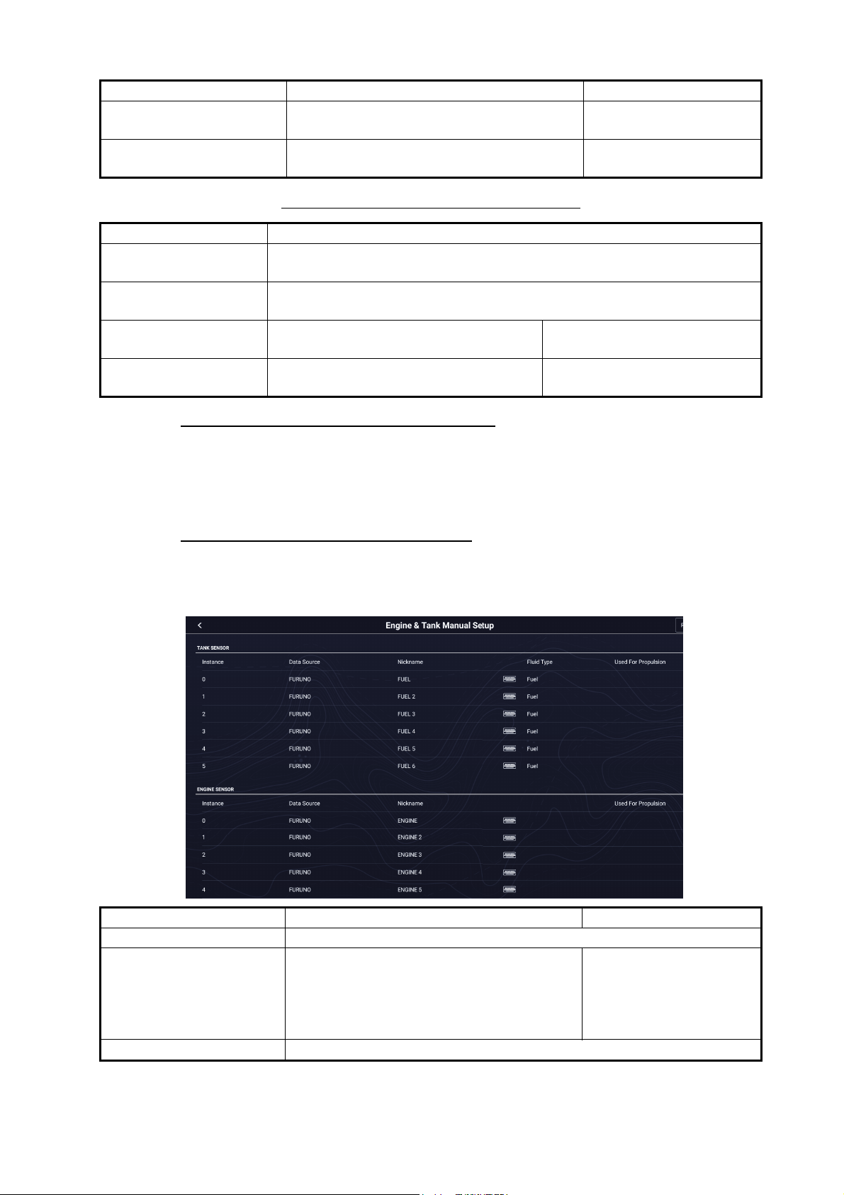
[Engine &Tank Automatic Setup] section
The TZTBBX will automatically detect engines and tanks connected to the same network.
0.00°C to 99.00°C
0.01°C to 999.00°C
This is the recommended method for setting up engines and tanks.
[Engine &Tank Manual Setup] section
The manual set up method should only be used if the automatic setup did not correctly
detect your engines or tanks.
Menu Item Description Options (setting range)
[Nickname] Change the nickname for the engine or tank.
[Used For Propulsion] Select which engine/tank is used to
calculate the distance which may be
traveled using the remaining fuel. [On] uses
the engine/tank for calculations, [Off]
ignores the engine/tank.
[Reset] Resets the engine/tank details to default.
20
Off, On
Page 26
3. HOW TO SET UP THE EQUIPMENT
User
RD253065-DRS_RADOME
User
OriginOrigin
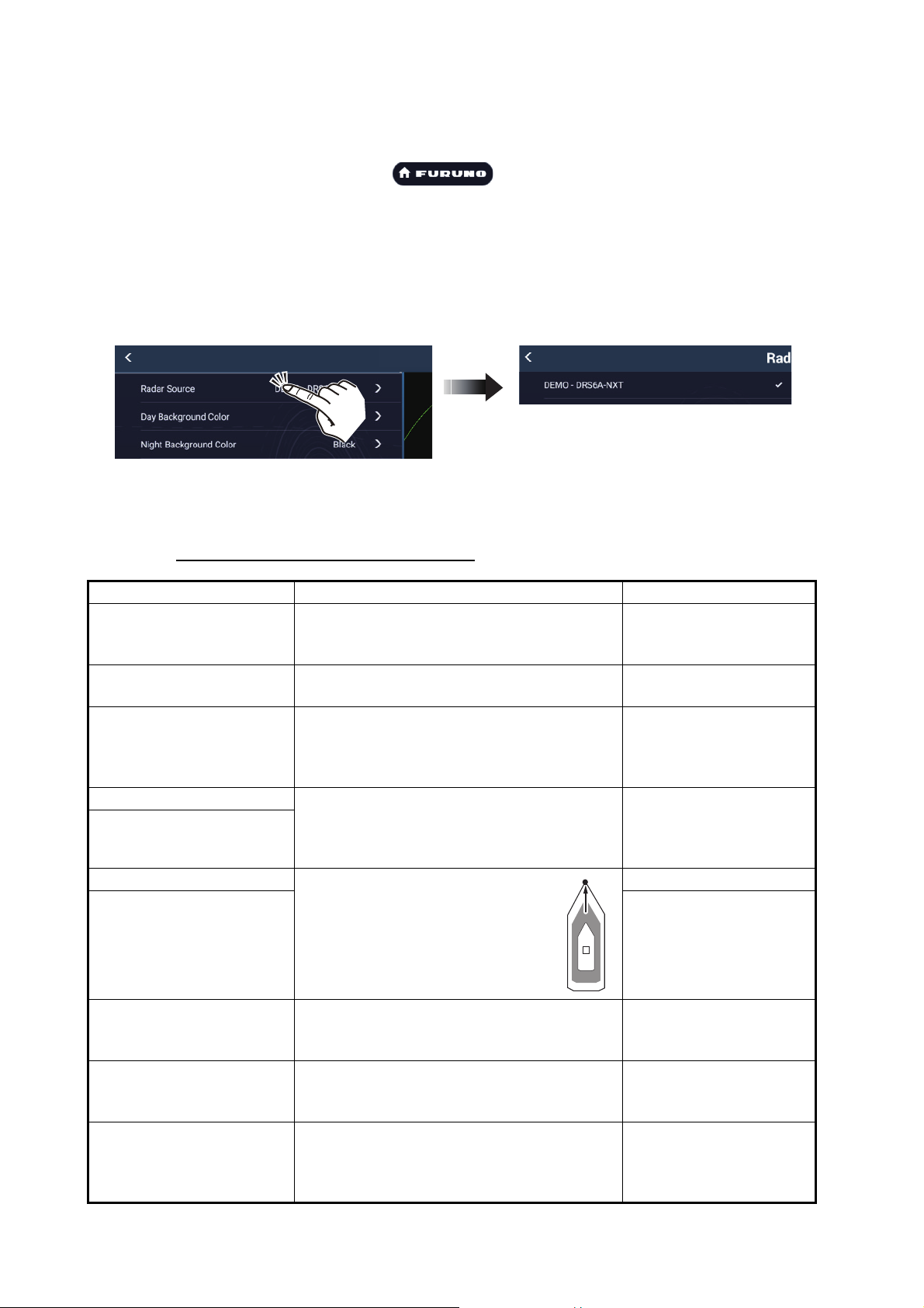
3.4 How to Set Up the Radar (For the service technician only)
1. Tap the FURUNO icon ( ) to show the home screen and display
mode settings.
2. Tap [Radar] from the [Settings] menu.
3. Tap [User Settings] [Radar Source], then select the appropriate radar sensor.
Note: If a DRS sensor is connected but does not appear in the [Radar Source] list,
close the list and open it again. The name of the DRS sensor should appear with
a check mark, as in the example below.
4. Scroll the [Radar] menu display to find the menu item [Radar Initial Setup], then
tap [Radar Initial Setup].
5. Referring to the tables which follow, set up the radar.
[Radar] menu - [Radar Initial Setup]
Menu item Description Options (setting range)
[Antenna Rotation] Select the speed of antenna rotation. Not
available (greyed out) with the radar sensor
DRS4DL+.
[Antenna Heading Align] See "How to align the antenna
heading" on page 3-22.
[Main Bang Suppression] If main bang appears at the screen center,
slide the circle icon so that the main bang
disappears, while watching the radar echo
at the left-hand side of the display.
[Enable Sector Blanking] Up to two sectors may be selected for
[Enable Sector 2 Blanking]
[Position from Bow] Referring to the figure on the right,
[Position from Port] -99 m to +99 m
blanking (no transmission). Select [ON] to
enable this feature. Set the start and end
angles (0° to 359°).
enter the radar antenna positioning
bow-stern (Longitudinal) and port-
starboard (Lateral) position from
the origin.
[Auto], [24 RPM]
-179.9° to +180.0°
0 to 100
On, Off
0 m to 999 m
Port-side is negative,
Starboard-side is positive.
[Height from Surface] Select the height of the antenna above the
waterline. Not available (greyed out) with
the radar sensor DRS4DL+.
[Auto Tuning] Enable/disable auto tuning for the connect-
ed radar. Not available (greyed out) with the
radar sensor DRS2D-NXT, DRS4D-NXT.
[Tuning Source] Select a display in the dual range display to
manually tune. Not available (greyed out)
with the radar sensor DRS2D-NXT,
DRS4D-NXT, DRS4DL+.
21
[Under 3m], [3m-10m],
[Over 10m]
Off, On
[Range1], [Range2]
Page 27
3. HOW TO SET UP THE EQUIPMENT
000
010
020
030
040
050
060
070
080
090
100
110
120
130
140
150
160
170
180
190
200
210
220
230
240
250
260
270
280
290
300
310
320
330
340
350
a
Target
Correct bearing
(relative to
heading)
Antenna mounted
error to port
(HDG SW advanced)
Picture appears
deviated
clockwise.
000
010
020
030
040
050
060
070
080
090
100
110
120
130
140
150
160
170
180
190
200
210
220
230
240
250
260
270
280
290
300
310
320
330
340
350
b
Target
Apparent position
of target
Correct bearing
(relative to
heading)
Correct bearing
(relative to
heading)
Apparent
position of
target
Apparent
position of
target
Antenna mounted
error to starboard
(HDG SW delayed)
Picture appears
deviated counterclockwise.
Front of antenna
Front of antenna
a
b
Menu item Description Options (setting range)
[Manual Tuning] Manually tune the radar. -50 to 50
[Radar Monitoring] Display various information regarding the connected radar.
[Radar Optimization] Automatically adjust magnetron output and tuning for the connected ra-
dar. Available when the [TX/STBY] setting is [ON]. Do not change these
settings. Not available (greyed out) with the radar sensor DRS2D-NXT,
DRS4D-NXT.
Note 1: For the service technician only.
Note 2: The service technician performs this whenever the magnetron
is replaced.
[ARPA Advanced
Settings]
For service technicians only. Do not change these settings.
This item is available when [TX/STBY] is [ON].
Not available (greyed out) with the radar sensor DRS4DL+, and FAR2xx8 series, FAR-2xx7 series and FAR-15x8 series radar antennas.
[TX Channel] Select [1], [2] or [3], the channel where the
interference is smallest. See the operator’s
manual for details. Available with the radar
sensor DRS2D-NXT, DRS4D-NXT.
[Target Analyzer Mode] You can emphasize rain clutter or target
echoes when the target analyzer is active.
Select [Rain] or [Target] as appropriate. See
the operator’s manual for details. Available
with the radar sensor DRS2D-NXT,
DRS4D-NXT, DRS6A-NXT and DRS12ANXT.
[Auto acquire by Doppler] When selecting [ON], approaching targets
(ships, rain clutter, etc.) within 3 NM from
own ship are automatically acquired by the
Doppler calculated from the radar echo.
See the operator’s manual for details. Available with the radar sensor DRS2D-NXT,
DRS4D-NXT, DRS6A-NXT and DRS12ANXT.
[Set Hardware to Factory
Default]
[Reset Default Page
Resets the radar selected at
[Radar Source] to factory default.
Resets [Radar] menu settings to default. [OK], [Cancel]
Settings]
[Auto], [1], [2], [3]
[Rain], [Target]
Off, On
[OK], [Cancel]
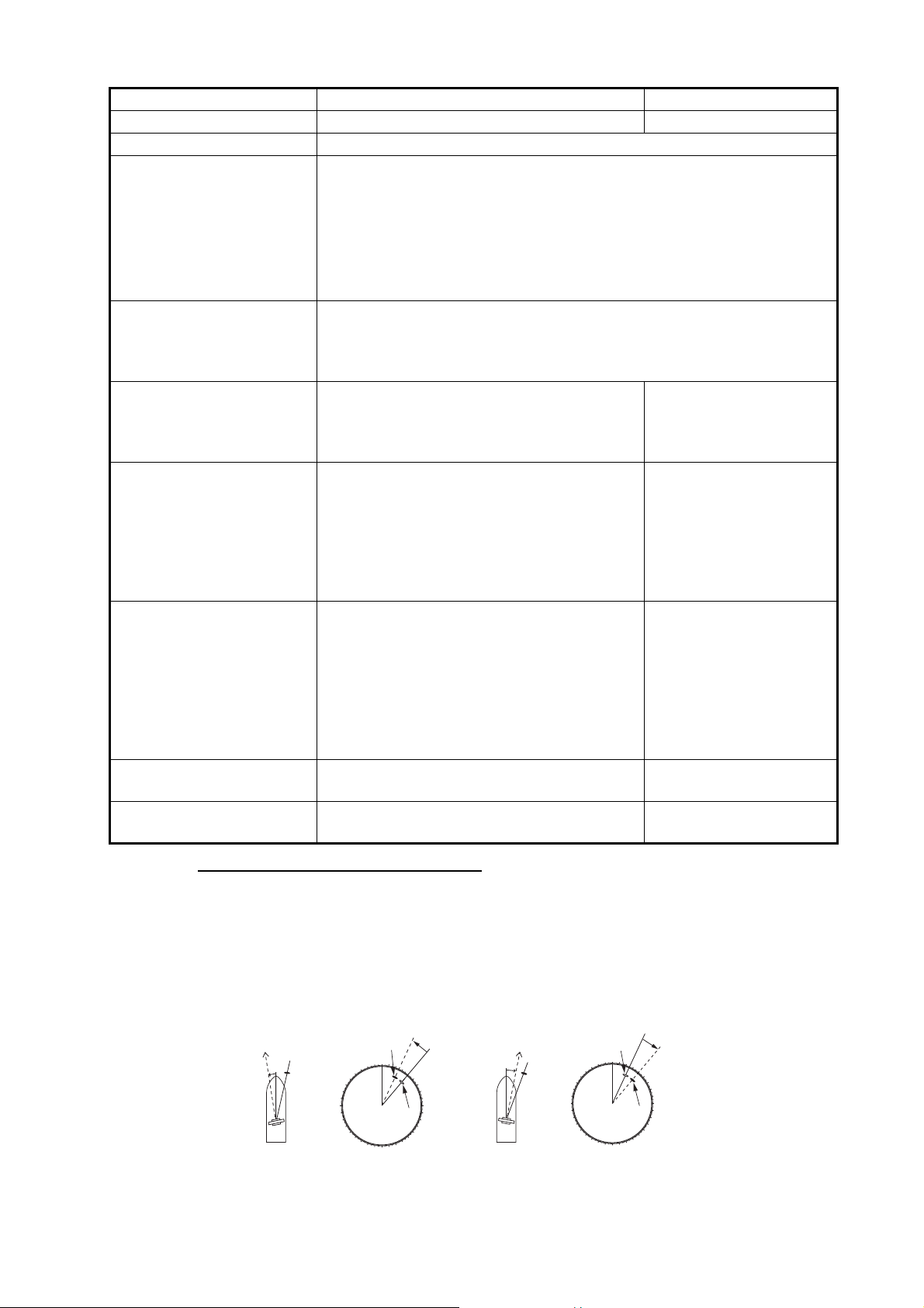
How to align the antenna heading
You have mounted the antenna unit facing straight ahead in the direction of the bow.
Therefore, a small but conspicuous target dead ahead visually should appear on the
heading line (zero degrees). In practice, you will probably observe some small bearing
error on the display because of the difficulty in achieving accurate initial positioning of
the antenna unit. The following adjustment will compensate for the error.
22
Page 28
3. HOW TO SET UP THE EQUIPMENT
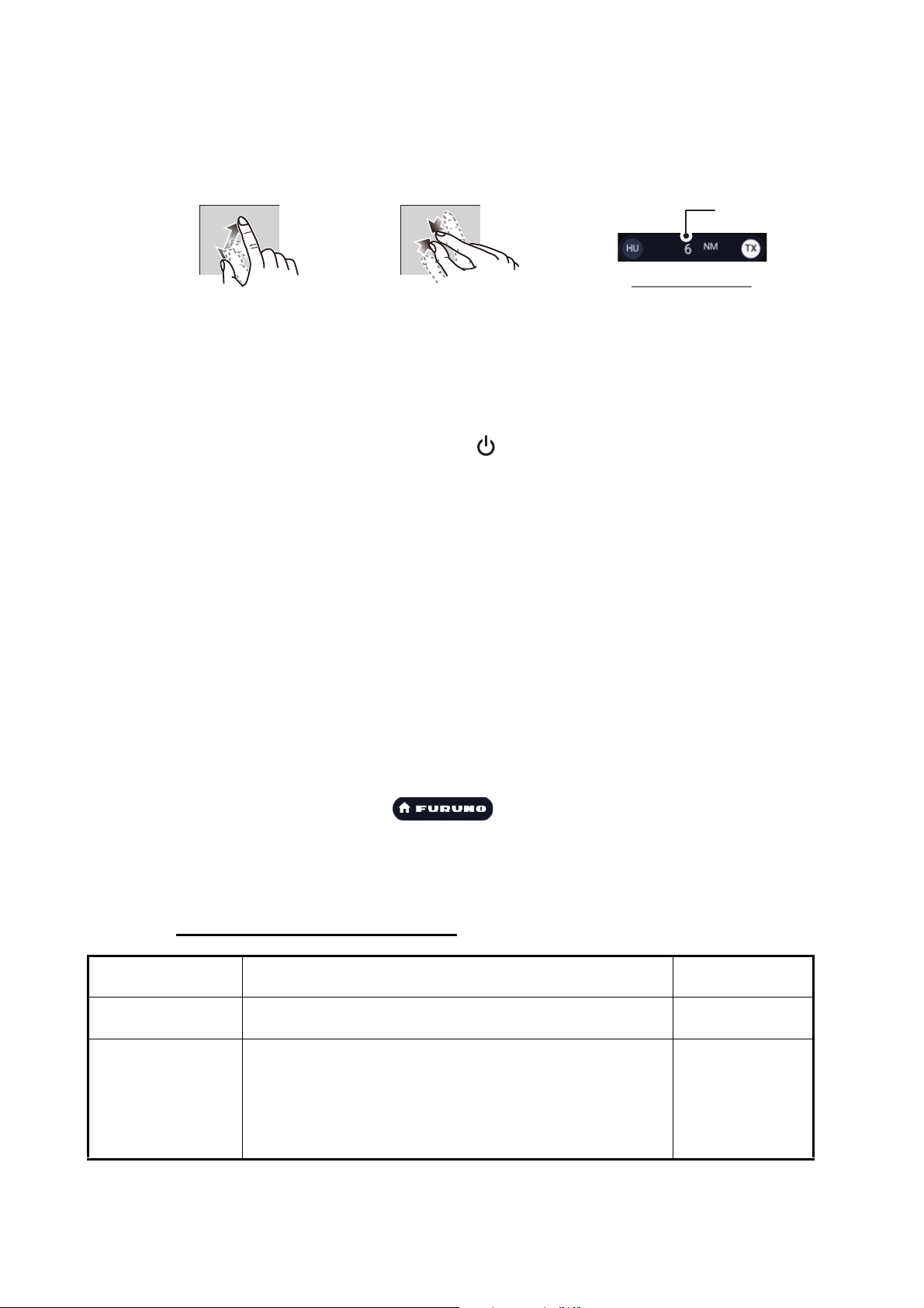
Zoom in
Zoom out
1. Set your radar with 0.125 and 0.25 nm range and the head up mode.
You can select a range by using the pinch action. The range appears at the bottom
right of the screen. Range may also be selected using the slide bar displayed on
the right-hand side of the radar display area. Drag the bar up to zoom in, or down
to zoom out.
Zoom in
Zoom out
2. Turn the vessel’s bow toward a target.
3. Tap the [Home] icon to show the home screen and display mode settings.
4. Tap [Radar] to show the [Radar] menu.
5. Tap [Radar Initial Setup] [Antenna Heading Align].
6. Key in an offset value (setting range: -179.9° to +180°) that puts the target at the
very top of the screen, then tap the icon.
+: rotate echo in clockwise direction
- : rotate echo in counterclockwise direction
7. Confirm that the target echo is displayed at correct bearing on the screen.
3.5 How to Set Up the Fish Finder
If you have an internal fish finder or BBDS1 or DFF series, set them up as shown in
this section. Set up each fish finder source individually. The fish finder source can be
selected with [Fish Finder Source], which is in the [Fish Finder] → [User Settings]
menu.
Range
Radar indications
Note 1: Some menu items are restricted to certain external depth sounders and some
menu items may not be available when using the internal depth sounder.
Note 2: For DFF-3D setup instructions, see the DFF-3D operator’s manual.
1. Tap the FURUNO icon ( ) to show the home screen and display
mode settings.
2. Tap [Settings], then tap [Fish Finder]
3. Refer to the table below to set up the fish finder.
[Fish Finder Initial Setup] section
Menu item Description
[Transducer Setup] Setup Transducer and Motion Sensor. See "[Transducer
Setup] section" on page 3-25.
[Preset Frequency
Setup]
Set to change the TX center frequency and CHIRP width.
Please refer to the instruction manual for details.
Note: This menu is available when DFF3-UHD or TZT9F/
12F/16F/19F is connected.
Options
(setting range)
[Preset Frequency 1 Setup],
[Preset Frequency 2 Setup],
[Preset Frequency 3 Setup]
23
Page 29
3. HOW TO SET UP THE EQUIPMENT
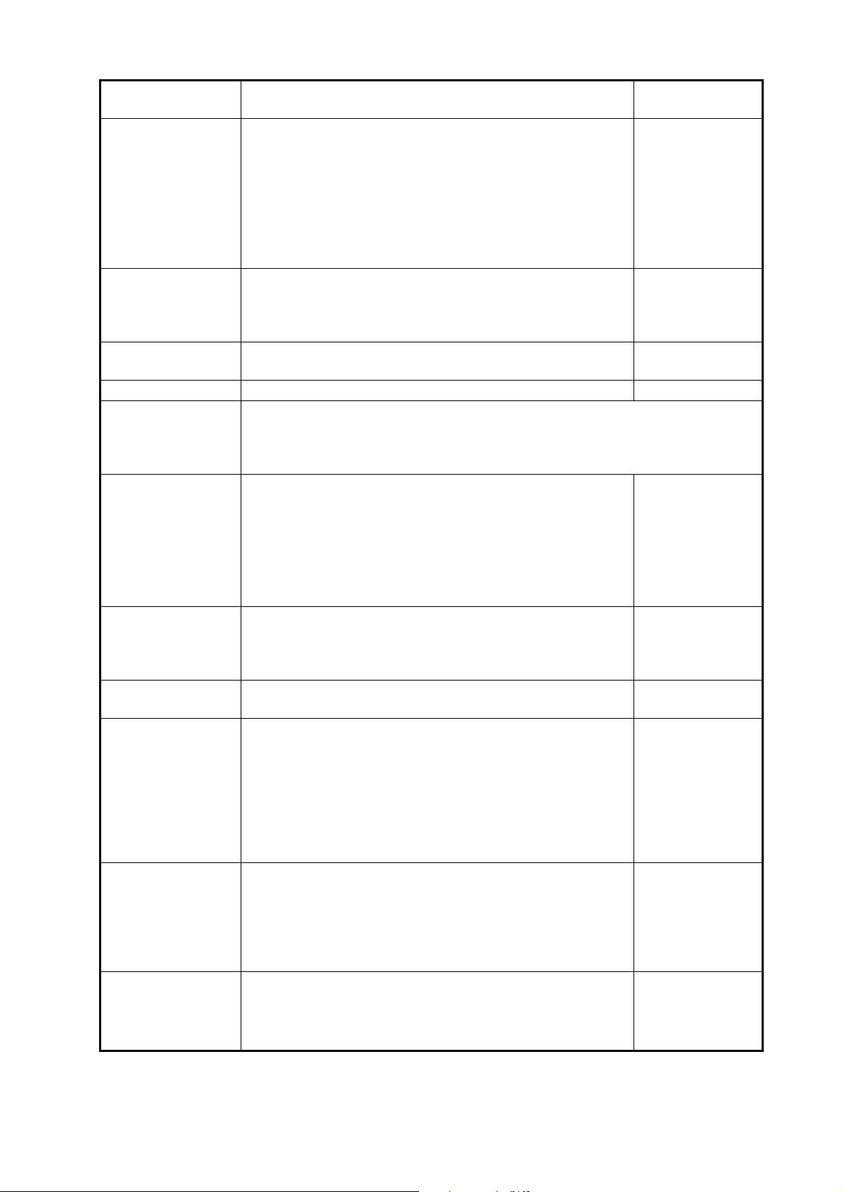
Menu item Description
[Zero Line
Rejection]
[Zero Line Range] You can set the zero line removal range by turning on
[Transducer Draft] Set the distance between the transducer and the draft line
[Salt Water] Select [ON] if you use this equipment in salt water. Off, On
[Fish Finder
Source]
[Transmission
Format]
When you turn the zero line (transmission line) rejection
on, the line is not shown, which allows you to see fish
echoes near the surface. The width of the line changes
with the transducer used and installation characteristics. If
the width of the line is 1.4 m or more, select [ON].
Note: If a DFF3 or DFF3-UHD is connected and this item
is set to [ON], set the range of rejection with [Zero Line
Range].
[Zero Line Rejection]. If the tail of the zero line is long, set
a large value. If the zero line still does not disappear, reduce the transmission power. The default setting is 2.0
to show the distance from the sea surface.
Set the fish finder to use. Select from a network fish finder (BBDS1,
DFF1,DFF3, DFF1-UHD, DFF3-UHD) or a built-in fish finder of this unit or
NavNet TZtouchXL series unit in the same network. Setting options for this
menu item depend on the equipment connected to this unit.
Select whether to transmit high and low frequencies simultaneously, or separately with a time delay. Normally, use
[Parallel], which transmits the frequencies simultaneously.
If you encounter interference near the bottom, select
[Sequential A] or [Sequential B] in order to suppress the interference.
Note: Shown with connection of DFF3-UHD.
Options
(setting range)
[OFF], [ON]
DFF3: 1.4 to 2.5
DFF3-UHD/Internal fishfinder: 1.4
to 3.8
0.0m to 99.9m
[Parallel],
[Sequential A],
[Sequential B]
[Transmission
Power Mode]
[External KP] Select on to synchronize with external sounder’s keying
[Bottom Level HF]
[Bottom Level MF]
[Bottom Level LF]
[Auto Gain Offset
HF]
[Auto Gain Offset
MF]
[Auto Gain Offset
LF]
[STC HF]
[STC MF]
[STC LF]
Set the TX power level. See the operator’s manual for details.
pulse.
The default bottom level setting (0) determines that two
strong echoes received in sequence are bottom echoes. If
the depth indication is not stable in the default setting,
adjust the bottom level here. If vertical lines appear from
the bottom echo in the bottom lock display, lower the
bottom level to erase the vertical lines.
If you can not identify the fish near the bottom from the
bottom echo, increase the bottom level.
If the auto gain offset is wrong, or there is a difference in
the gain between the low and high frequencies, set an
offset here to balance auto gain for the two frequencies.
Adjust the low (LF) or high (HF) STC frequency.
See the operator’s manual for details.
Note: Shown with connection of DFF3, DFF1-UHD or
DFF3-UHD.
DFF1-UHD: [Off],
[Min], [Auto]
DFF3-UHD: 0 to
10
Off, On
-40 to +40
-5 to +5
0 to +10
24
Page 30
3. HOW TO SET UP THE EQUIPMENT
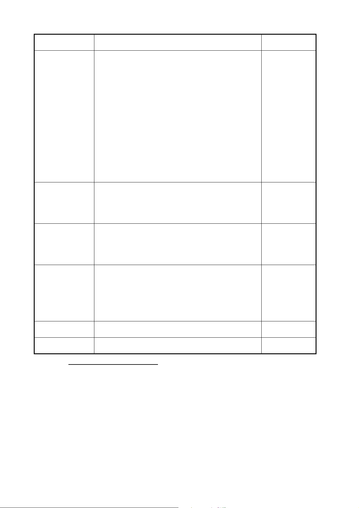
Menu item Description
[TX Pulse HF]
[TX Pulse MF]
[TX Pulse LF]
[RX Band HF]
[RX Band MF]
[RX Band LF]
The pulse length is automatically set according to range
and shift, however it can also be set manually. Use a short
pulse for better resolution and a long pulse when detection
range is important. To improve resolution on zoom displays, use [Short 1] or [Short 2].
• [Short 1] improves the detection resolution, but the detection range is shorter than with [Std] (pulse length is 1/
4 of [Std]).
• [Short 2] raises the detection resolution, however detection range is shorter (pulse length is about 1/2 of [Std])
than [Std].
• [Std] is the standard pulse length, and is suitable for
general use.
• [Long] increases the detection range but lowers the resolution (about 1/2 compared to the [Std] pulse length)
Note: Shown with connection of DFF3 or DFF3-UHD connected to a narrow band width transducer.
Set the bandwidth for low (LF) or high (HF) frequency. The
RX bandwidth is automatically set according to pulse
length. To decrease noise, select [Narrow]. For better
resolution, select [Wide].
Note: Shown with connection of DFF3, DFF3-UHD.
Options
(setting range)
[Short1],
[Short2],
[Standard],
[Long]
[Narrow],
[Standard],
[Wide]
[Temperature Port] Set the data source for water temperature.
• [MJ]: Use the temperature/speed sensor for data.
• [Low Frequency]: Use the LF sensor for data.
• [High Frequency]: Use the HF sensor for data.
Note: Shown with connection of DFF3, DFF1-UHD.
[Fish Finder Demo
Mode]
[Set Hardware to
Factory Default]
[Restore Default
Page Settings]
The demo mode provides simulated operation using data
stored in the internal memory.
• [Off]: Disable the demo mode.
• [Shallow]: Enable shallow water demo mode.
• [Deep]: Enable deep water demo mode.
Note: Shown with connection of BBDS1, DFF1, DFF3,
DFF1-UHD or DFF3-UHD.
Reset the external fish finder to its factory default settings. [OK], [Cancel]
Restore all menu settings to default. [OK], [Cancel]
[Transducer Setup] section
For motion sensor related settings, see "Motion sensor menu" on page 3-27.
From [High Frequency Min] to [Low Frequency Max] is shown only when DFF3-UHD
is connected.
[MJ],
[Low Frequency],
[High Frequency]
[Off], [Shallow],
[Deep]
Note: Make sure that the unit is set to stand-by when setting up the transducer.
25
Page 31
3. HOW TO SET UP THE EQUIPMENT
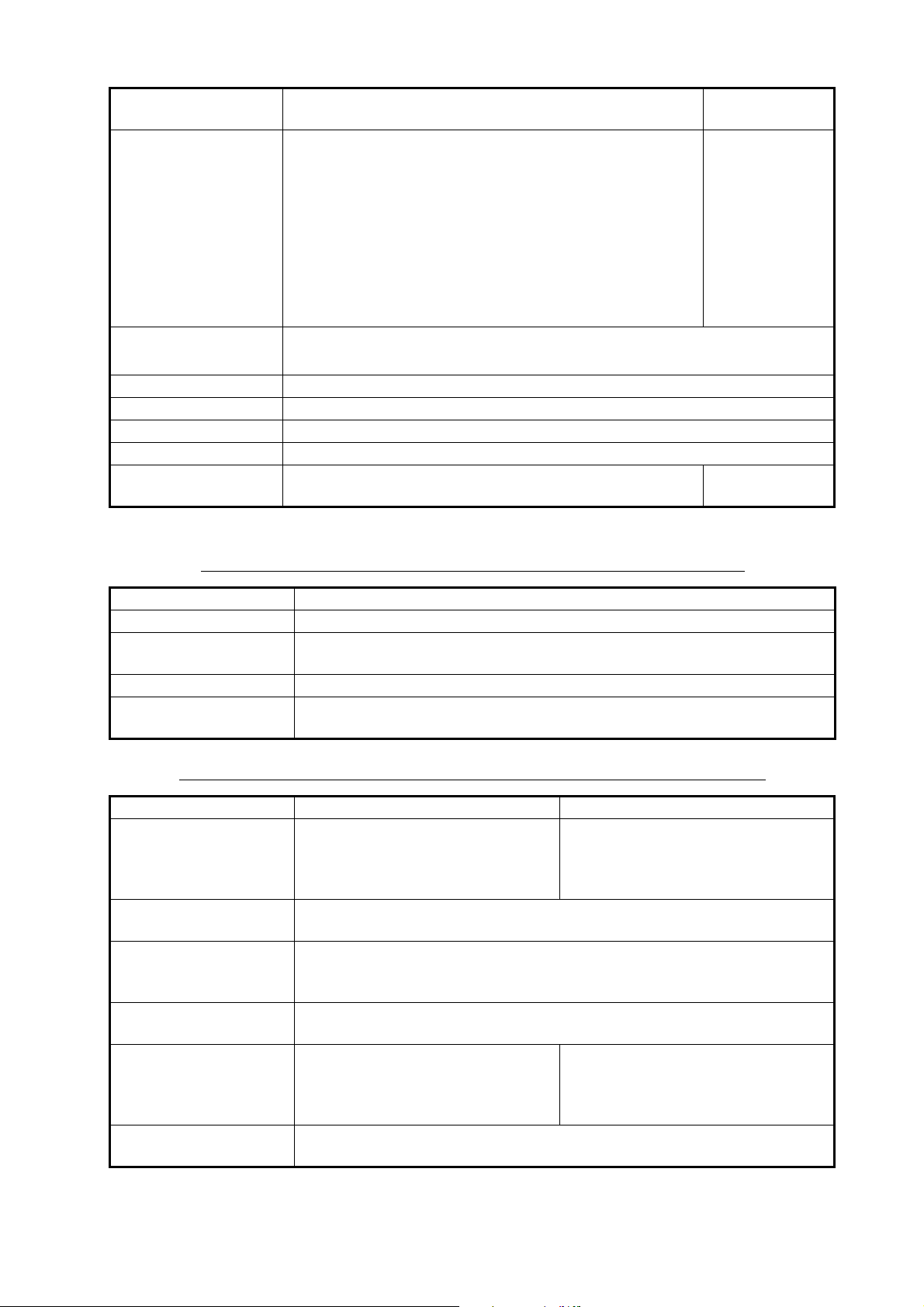
Menu item Description
[Transducer Setup
Type]
[Model Number] Select the appropriate model number from the list.
[High Frequency Min] Display the high frequency minimum.*
[High Frequency Max] Display the high frequency maximum.*
[Low Frequency Min] Display the low frequency minimum.*
[Low Frequency Max] Display the low frequency maximum.*
[Reset Default Page
Settings]
Select the type of transducer connected.
When the connected sounder is a DFF1-UHD and the
transducer has a compatible TDID, [TDID] is automatically selected.
Note: When the transducer model is changed or TDID is
detected, the frequency and bandwidth set on [Manual] is
to be reset.
• [Manual]: Manually set up the transducer.
• [Model]: Select the appropriate transducer model
(for FURUNO or AIRMAR transducers).
Note: Only available when [Transducer Setup Type] is set to [Model].
Reset the [Transducer Setup] menu settings to default. [OK], [Cancel]
*: Shown with connection of DFF3.
Options
(setting range)
[Manual],
[Model]
When [Transducer Setup Type] is set to [Model] and connected to DFF3
Menu item Description
[High Frequency] Set the frequency (kHz) of the connected high frequency transducer.
[Frequency Adjust HF] Fine-tune the high-frequency TX frequency to eliminate interference (set-
ting range: -50 to +50). Set to [0] where there is no interference.
[Low Frequency] Set the frequency (kHz) of the connected low frequency transducer.
[Frequency Adjust LF] Fine-tune the low frequency TX frequency to eliminate interference (set-
ting range: -50 to +50). Set to [0] where there is no interference.
When [Transducer Setup Type] is set to [Model] and connected to DFF3-UHD
Menu item Description Options (setting range)
[TX Mode HF] Band adjustment mode for center
frequency and CHIRP frequency of
the transducer connected to the
high frequency side.
[High Frequency] Set the high frequency (kHz) of the transducer connected to the high fre-
quency side.
[Frequency Adjust HF] If [FM (Manual CHIRP)] or [CW (Fixed Frequency)] is selected at [TX
Mode HF], fine-tune the high-frequency TX frequency to eliminate interfer-
ence (setting range: -50 to +50). Set to [0] where there is no interference.
[CHIRP Width HF] If [FM (Manual CHIRP)] is selected in [TX Mode HF], set the CHIRP fre-
quency band of the transducer connected to the high frequency side.
[TX Mode LF] Band adjustment mode for center
frequency and CHIRP frequency of
the transducer connected to the
low frequency side.
[Low Frequency] Set the low frequency (kHz) of the transducer connected to the low fre-
quency side.
[Auto CHIRP], [FM (Manual
CHIRP)], [CW (Fixed Frequency)]
[Auto CHIRP], [FM (Manual
CHIRP)], [CW (Fixed Frequency)]
26
Page 32
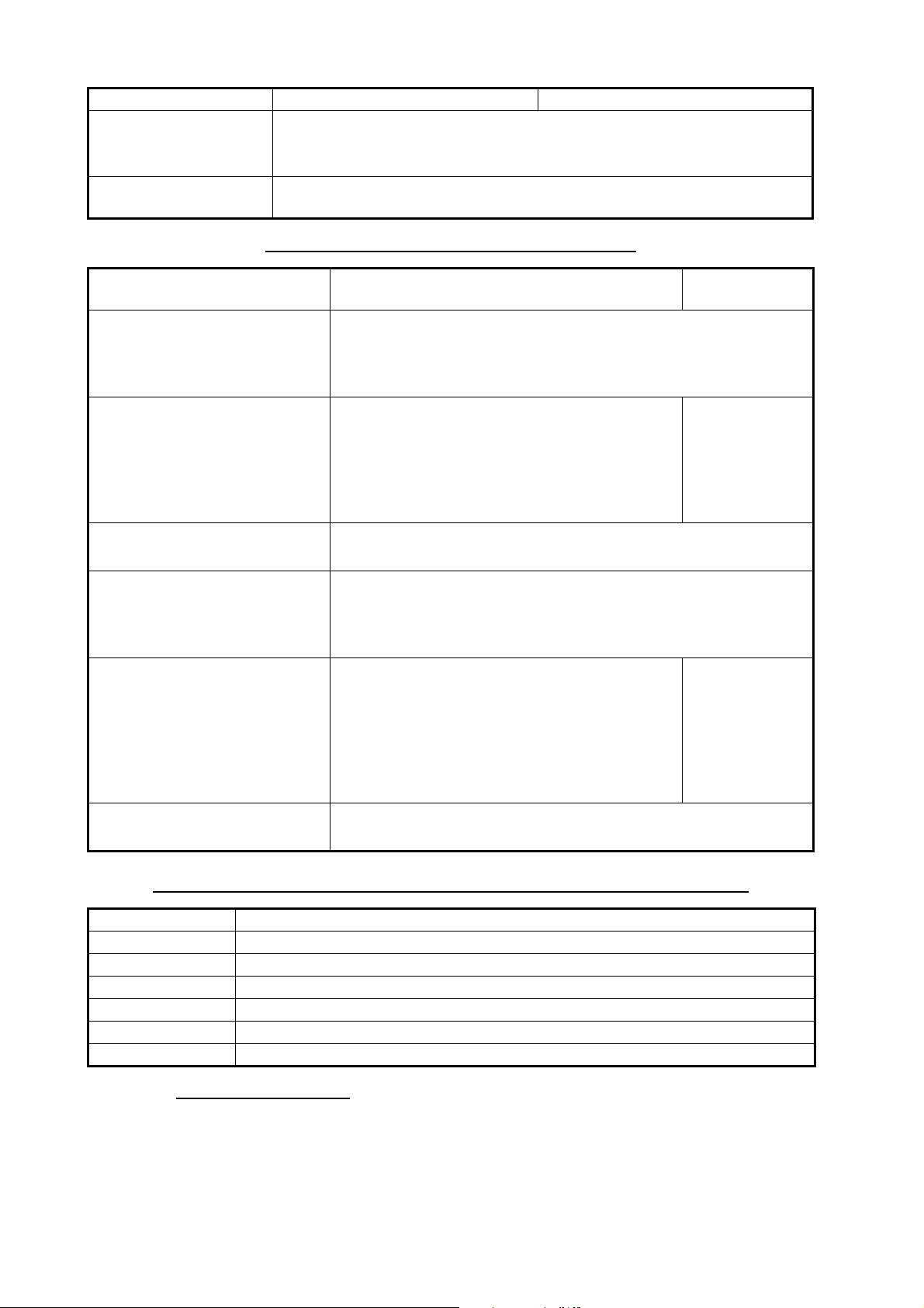
3. HOW TO SET UP THE EQUIPMENT
Menu item Description Options (setting range)
[Frequency Adjust LF]
[CHIRP Width LF] If [FM (Manual CHIRP)] is selected in [TX Mode LF], set the CHIRP fre-
If [FM (Manual CHIRP)]
Mode LF], fine-tune the low-frequency TX frequency to eliminate interference (setting range: -50 to +50). Set to [0] where there is no interference.
quency band of the transducer connected to the low frequency side.
or [CW (Fixed Frequency)] is selected at [TX
When [Transducer Setup Type] is set to [Manual]
Menu item Description
[High Frequency] Set the kHz frequency for high frequency. Setting ranges vary
depending on the transducer connected.
Note: Shown with connection of DFF1, BBDS1, DFF3, DFF1UHD.
[Transducer Power HF] Set the transmission power for high frequency.
Note 1: Shown with connection of DFF1,
BBDS1, DI-FFAMP or DFF3-UHD.
Note 2: For DFF1-UHD users, when the connected transducer TDID is not supported by the
DFF1-UHD, the setting is fixed as [1000].
[Band Width (HF)] Set the bandwidth for high frequency.
Note: Shown with connection of DFF3.
[Low Frequency] Set the kHz frequency for low frequency. Setting ranges vary
depending on the transducer connected.
Note: Shown with connection of DFF1, BBDS1, DFF3, DFF1UHD.
[Transducer Power LF] Set the transmission power for low frequency.
Note 1: Shown with connection of internal fish
finder, DFF1, BBDS1, DI-FFAMP and DFF3UHD.
Note 2: For DFF1-UHD users, when the connected transducer TDID is not supported by the
DFF1-UHD, the setting is fixed as [1000].
Options
(setting range)
[600], [1000]
[600], [1000]
[Band Width (LF)] Set the bandwidth for low frequency.
Note: Shown with connection of DFF3.
When [Transducer Setup Type] is set to [Manual] and connected to DFF3-UHD
Menu item Description
[TX Volt HF] Set the TX voltage (V) of the transducer connected to the high frequency side.
[TX Volt LF] Set the TX voltage (V) of the transducer connected to the low frequency side.
[High Frequency] Set the frequency (kHz) of the transducer connected to the high frequency side.
[Low Frequency] Set the frequency (kHz) of the transducer connected to the low frequency side.
[TX Power HF] Set the Power of the transducer connected to the high frequency side.
[TX Power LF] Set the Power of the transducer connected to the low frequency side.
Motion sensor menu
The [Motion Sensor] menu sets up the motion sensor, which provides for stable display of the seabed, schools of fish, etc. in moderate-to-rough seas.
Note 1: For connection of NMEA0183 equipment to the TZTBBX, ask your FURUNO
dealer to set up the equipment.
27
Page 33
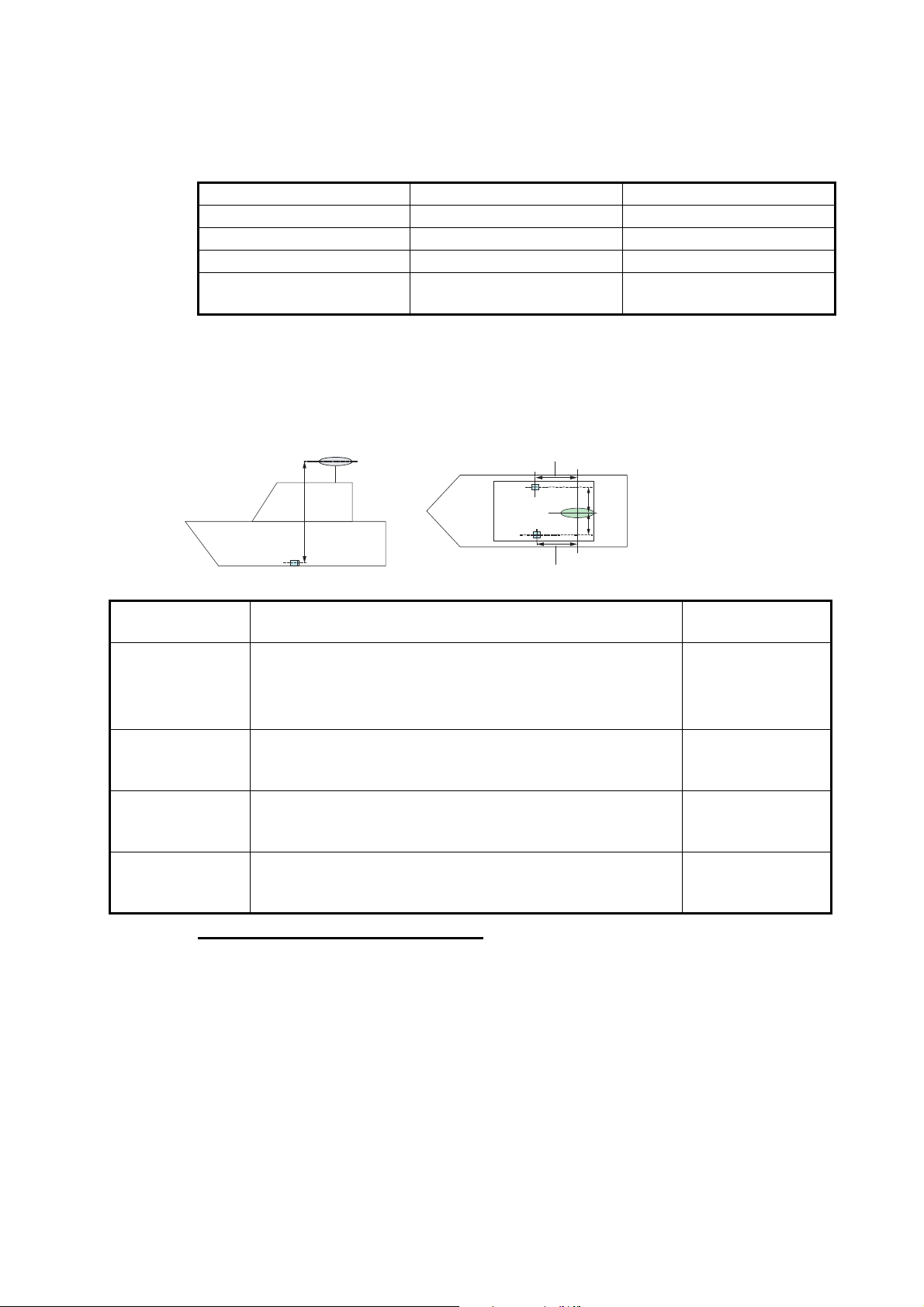
3. HOW TO SET UP THE EQUIPMENT
SC-30/33/50/70/110/130
Up/DownUp/Down
Bow/Stern for HFBow/Stern for HF
Bow/Stern for LFBow/Stern for LF
Port/Starboard for HFPort/Starboard for HF
Port/Starboard for LFPort/Starboard for LF
HF TransducerHF Transducer
LF TransducerLF Transducer
Note 2: To use the heaving function, the following settings are required at the satellite
compass. For the setting procedure, see the operator’s manual for your satellite compass. Settings for SC-30 are done from the [IF-NMEASC] menu, settings for SCX-20
is done from the [DATA OUT] menu.
NMEA 0183 NMEA 2000
Sentence ATT, HVE
Baud rate 38400BPS
Cycle 25ms
PGN Heave: 65280
Attitude: 127257
The [MOTION SENSOR] menu appears in the [Transducer Setup] menu when the
[Heaving Correction] is activated in the [Fish Finder] menu. If the satellite compass
SC-30 or SC50/110 is connected, set the distance between the antenna unit (or sensor) of the satellite compass and transducer (high and low if connected) here.
Menu item Description
[Motion Sensor
Type]
[Antenna Position Bow/Stern
HF (LF)]
[Antenna Position Up/Down HF
(LF)]
[Antenna Port/
Starboard HF
(LF)]
Select the sensor connected to your TZTBBX unit. For all
sensors other than SC-50 and SC-110, select [SC-30].
Note: This menu item is not available when [Fish Finder
Source] is set to [TZTBBX].
Set the distance from the antenna unit to the transducer in
the bow-stern direction. If the transducer is located on the
fore side, set a positive value.
Set the distance from the transducer to the antenna unit in
the vertical direction.If the transducer is located on the bow
side, set a positive value.
Set the distance from the antenna unit to the transducer in
the port-starboard direction. If the transducer is located on
the starboard side, set a positive value.
Transducer mis-mount correction
If the DFF-3D or a CHIRP side scan compatible transducer is installed 180° in reverse
(facing stern), turn on the following item:
• DFF-3D: [Settings]→[Multi Beam Sonar]→[Initial Setup]→[Transducer Setup]→[Transducer Mis-mount Correction]→[ON]
Options
(setting range)
[SC30],
[SC50_SC110]
-99.9 to +99.9
0.00 to +99.9
-99.9 to +99.9
• CHIRP Side Scan: [Settings]→[CHIRP Side Scan]→[Transducer Mis-mount Cor-
rection]→[ON]
28
Page 34
3. HOW TO SET UP THE EQUIPMENT
3.6 Wireless LAN Setting
3.6.1 How to join an existing wireless network
By connecting to an existing network, you may download software updates and
weather information from the Internet.
1. Tap the [FURUNO] icon ( ) to show the home screen and display
mode settings.
2. Tap [Settings], then [General].
3. Tap [Wireless LAN Settings].
4. Tap [Wireless Mode].
5. Tap [Connect to existing LAN], then tap the [<] icon at the top left of the
display.
6. Tap [Wireless] in the [ENABLE WIRELESS] menu.
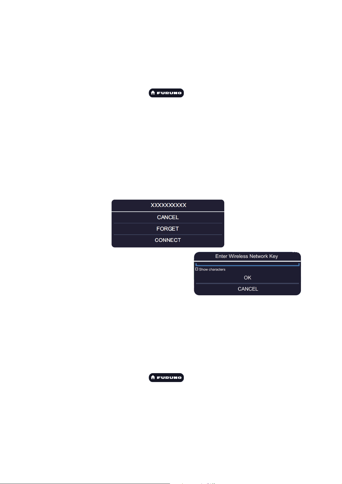
7. Tap [Scan] to scan the vicinity for accessible WLAN networks. Available networks
are listed. To delete all WLAN networks, select [Forget All Available Networks].
8. Tap the appropriate WLAN network to show the following display.
9. Tap [Connect], and the display shown in
the right figure appears.
10. Use the software keyboard to enter the
network key, then tap the [OK] button. To
see what you have input, check [Show
characters].
Note: If the network key is incorrect, an error message appears. Enter the correct
key and tap [OK] again.
11. Tap [X] on the title bar to close the menu.
3.6.2 How to create a wireless LAN network
Smart devices connected to this wireless network may also connect directly to the unit,
allowing use of the TZTBBX applications.
1. Tap the [FURUNO] icon ( ) to show the home screen and display
mode settings.
2. Tap [Settings] then [General], in that order.
3. Tap [Wireless LAN Settings].
4. Tap [Wireless Mode] in the [WIRELESS MODE] menu.
5. Tap [Create Local Network], then tap the [<] icon at the top left of the display.
6. Tap [Name] in the [LOCAL NETWORK SETTINGS] menu.
29
Page 35

7. Using the software keyboard, name the unit, then tap the .
8. Tap [Password] in the [LOCAL NETWORK SETTINGS] menu.
9. Using the software keyboard, set the password, then tap the .
10. Tap [Local Network] in the [ENABLE LOCAL NETWORK] menu to activate the
wireless network.
11. Your smart device may now be connected to the unit, through the network.
1) From the smart device, select the network set at step 7.
2) Input the password set at step 9.
12. Tap [] on the title bar to close the menu.
3.7 Ferry Mode
Note: Only the SC-30, SC-33, and SCX-20 support the Ferry Mode.
The Ferry mode allows the user to rotate the screen orientation by 180°. Note that all
the above heading sensors must support heading offset command from the TZTBBX.
Both the heading sensor and radar sensor must be powered when the TZTBBX sends
the heading offset command to them. If TZTBBX sends the command and one of the
sensors does not receive it, the heading data may be reversed. See "[Event Input
Configuration]" of "Other menu items" on page 3-18.
3. HOW TO SET UP THE EQUIPMENT
3.8 How to Manage Your Charts
A TZ MAPS world chart is provided standard. For all other TZ MAPS charts you will
need to purchase and load a chart license together with an unlock code. (The same
applies to MM3D charts.) To share the system ID and unlock code between NavNet
TZtouch series units connected within the same network, go the Home page on any
unit[Settings][Initial Setup]turn on [Chart Master].
Note: If two or more NavNet TZtouch series devices share an unlock code, it is necessary to obtain a new unlock code when changing the Chart Master settings. For example, one unit is set as "main" (Chart master setting: ON) and the other unit
as"secondary" (Chart master setting: OFF), you need to reacquire an unlock code.
3.8.1 How to update or add TZ MAPS charts
By connecting this device to the Internet and logging into My TIMEZERO™, you can
purchase and renew a TZ MAPS chart license (valid for one year) and download chart
data online. Downloaded chart data can be used even when offline by putting it on a
microSD card and inserting it into the card slot on the back of the device.
Note 1: Chart licenses are valid for one year, and during this period charts can be
downloaded and updated. After the license period expires, you can continue to use
the already downloaded charts. However, charts cannot be downloaded or updated.
After the one-year period, you can purchase a new chart license, which will be automatically renewed yearly. To cancel the automatic renewal, go to your My TIMEZE-
™
RO
account, using the link below. The automatic renewal cannot be canceled from
the device side.
https://extranet.mytimezero.com/
30
Page 36
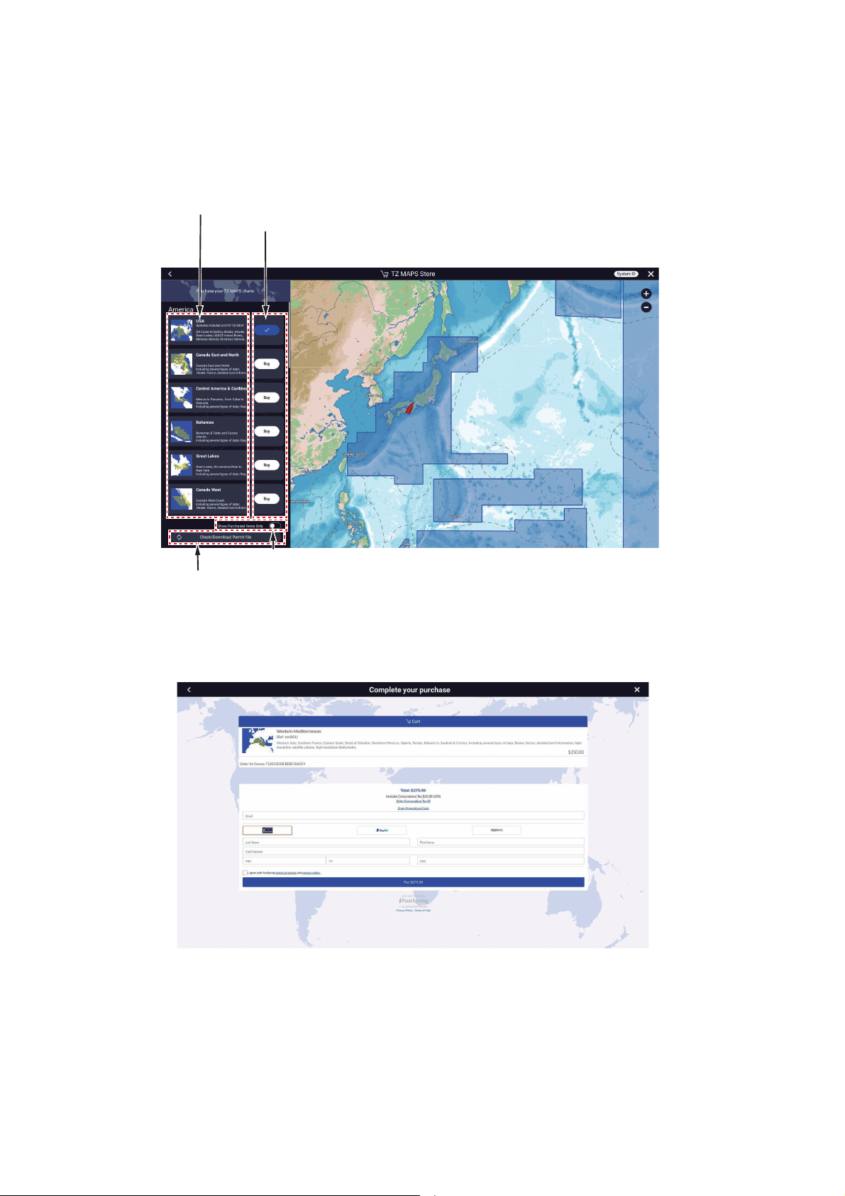
3. HOW TO SET UP THE EQUIPMENT
Tap here to highlight the selected area, on the right side of the screen
(White background: Not purchased, Blue background: Purchased).
[Buy]: Not purchased, [ 㾎]: Purchased
*: When the license expires (one year), the indication
changes to [Subscribe], and when you select and purchase
a subscription, the indication changes to [Subscribed].
Tap to check whether there is a license for the purchased chart. If there is,
the file will be downloaded. After downloading, the [Buy] button of the
purchased chart changes to a blue button, and you can then download
the chart data for the purchased area
㾎.
Turn ON to display only purchased charts.
Note 2: When purchasing a chart license directly from this equipment, make the following settings to avoid leaking input information.Home page[Settings][Gener-
al][This Display][Allow Remote Control][Off].
1. Home page[Charts][TZ MAPS Store].
2. Tap the [Buy] button corresponding to the area to purchase. The message
"Please wait, preparing your purchase" appears then the “buy screen” appears.
31
Page 37
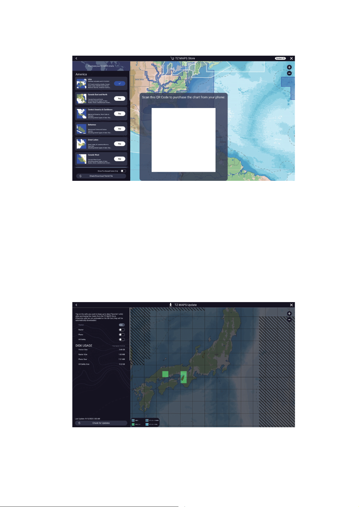
3. HOW TO SET UP THE EQUIPMENT
QR Code
If you are not connected to the Internet, a QR code appears. Use your smartphone/tablet to read it and display the “buy screen”.
3. Select how to buy the chart.
4. Enter the required information.
5. Read the conditions of purchase, check to agree, then tap [Payment].
6. If you purchase a license using a QR code, a ZUC file is sent to your registered
email address. Save the file to a USB flash memory, insert the memory into the
USB port of this equipment, and read the file.
3.8.2 How to update TZ MAPS charts
If there is a new version of a downloaded chart data, there are two ways to update the
chart, individually or all at once.
1. Home page[Charts][TZ MAPS Update].
2. Update chart data collectively: Tap [Check for Updates], at the bottom left corner
of the screen,
Update chart data individually: Tap the area you want to update.
32
Page 38
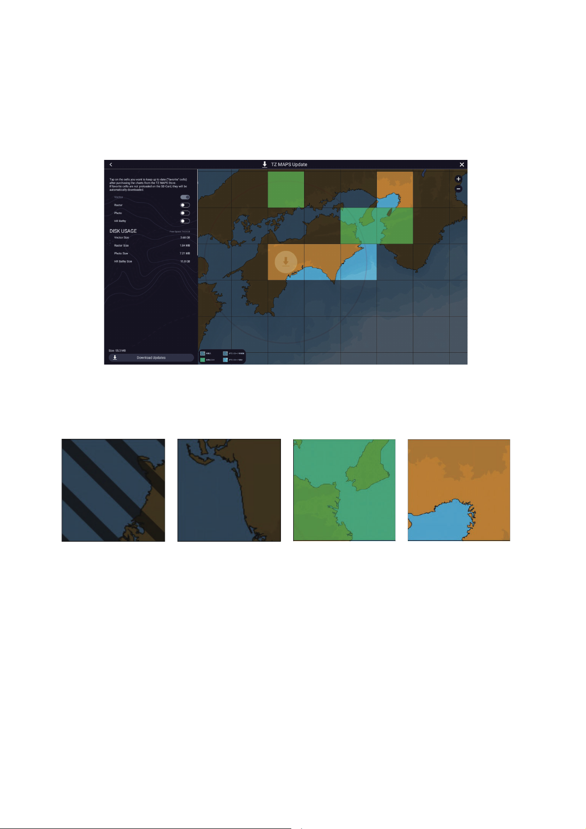
3. HOW TO SET UP THE EQUIPMENT
Not purchased Not downloaded Favorites
Download completed
The update begins and progress is indicated at the bottom left corner of the
screen. The [Check for Updates] button label changes to [Cancel], and when the
update is completed it changes to [Download Updates].
For individual download, the selected area is given [Favorites]* status, Tap [×] on
the title bar to close the [TZ MAPS Update] screen and complete the process.
For collective download, an icon appears in the areas that can be updated. You
can update multiple areas. The following screen appears.
*: Depending on the status of chart data, each area is classified and displayed into
the following four types. Areas set as [Favorites] are automatically updated if the
latest data is available. [Favorites] switches between [Favorites] and [Downloaded] each time you tap an area.
3. Tap [Download Updates] at the bottom left corner of the screen. The download begins and progress is indicated at the bottom left corner of the screen. The [Download Updates] button label changes to [Cancel] and then [Downloaded] once the
download is complete.
4. Tap [×] on the title bar to finish the download and close the [TZ MAPS Update]
screen.
33
Page 39
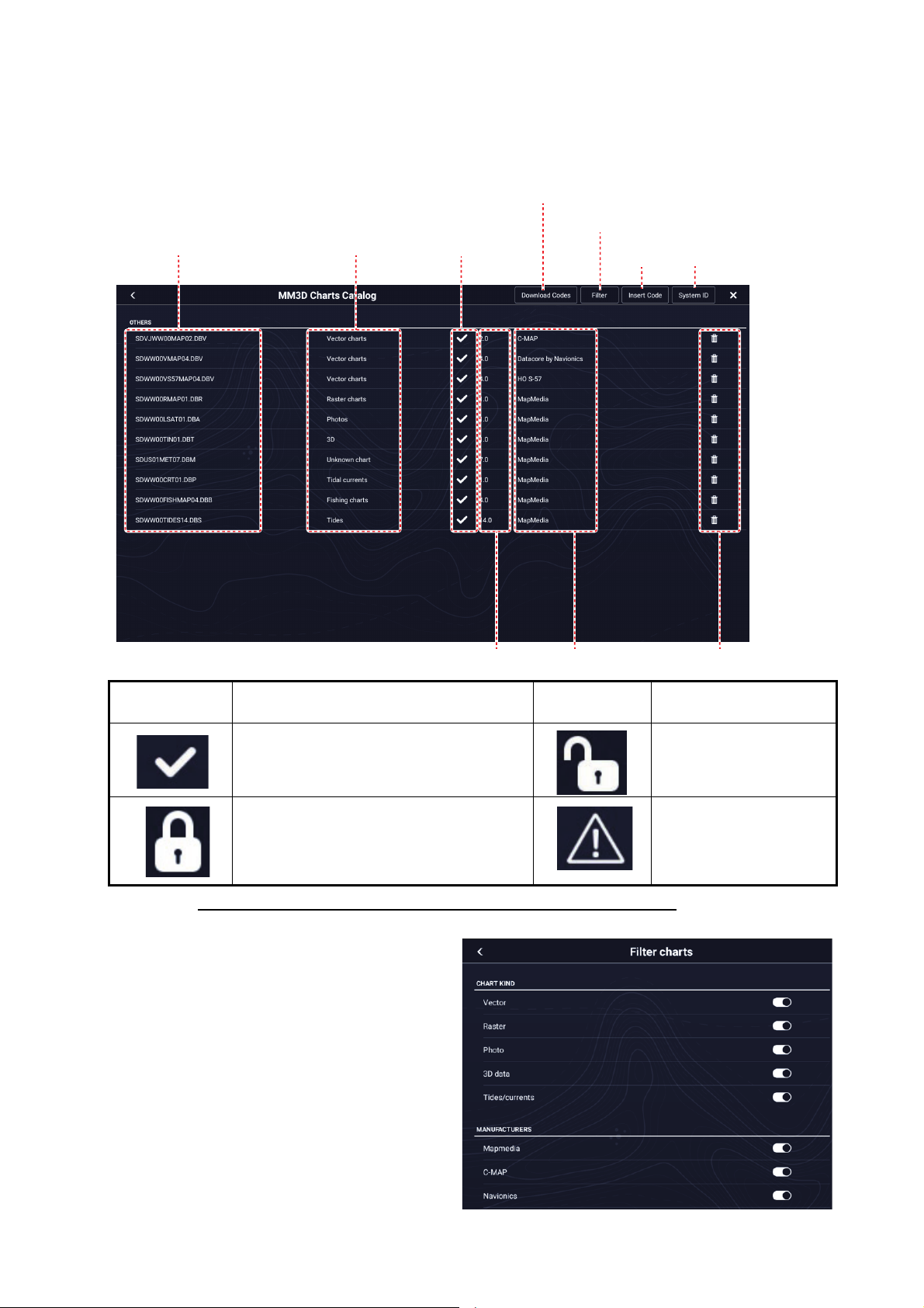
3. HOW TO SET UP THE EQUIPMENT
3.8.3 How to display the MM3D charts catalog
The charts catalog shows all the charts incorporated in your equipment. To show the
charts catalog, Home page→[Charts]→[MM3D Charts Catalog].
Tap to dowload chart
Chart file name
Chart file type
unlock codes.
See table
below.
Tap to show [FIlter charts] pop-up menu.
Tap to enter
unlock code
System ID
display
Chart status
icon
How to hide unnecessary charts on the chart catalog list
1. Tap [Filter] on the chart cata-
2. Turn off items to hide in
Chart version no.
Meaning
Free chart. An unlock code is not necessary.
Paid chart. Unlock code is necessary to
use the chart. Tap [Insert Code] at the
top of the [Charts Catalog] screen. Enter
the unlock code then tap [] to finish.
log list title bar to show the
[Filter charts] window.
[Chart Kind], and [Manufacturers] (Mapmedia, C-MAP,
Navionics, NOAA, IHO) To
restore all charts, tap [Reset
Filters].
Note: To restore all items to
default (all ON), tap [Reset
Filters].
Chart manufacturer
Chart status
icon
Trash icon
Meaning
Paid chart. Unlock code
entered.
Chart cannot be used
because it is corrupted.
34
Page 40

3. HOW TO SET UP THE EQUIPMENT
3. Tap < on the title bar to return to the chart catalog list. [Filter] on the title bar changes to [Change Filter].
4. Tap the close button to close the chart catalog list.
3.8.4 How to add MM3D charts
For information on how to obtain a chart and the unlock code, contact the point of purchase, or the nearest branch/sales office of our company. Copy the chart to a microSD
card and insert it into the card slot on the back of the equipment. If you have added a
paid chart, please enter the unlock code (see the section 3.8.3).
3.8.5 How to MM3D charts
To delete charts, go the Home page then tap [Charts]→[MM3D Chart Catalog]. Tap
the trash can icon (right edge of screen) corresponding to the chart to delete. You are
asked if you are sure to delete the chart. Tap [OK] to delete the chart.
3.9 IP Camera Setup
When connecting one or more IP camera (maximum 8), the following settings are required at the camera.
• IP Address: 172.31.xxx.xxx~172.31.xxx.xxx
• Subnet Mask: 255.255.0.0
35
Page 41
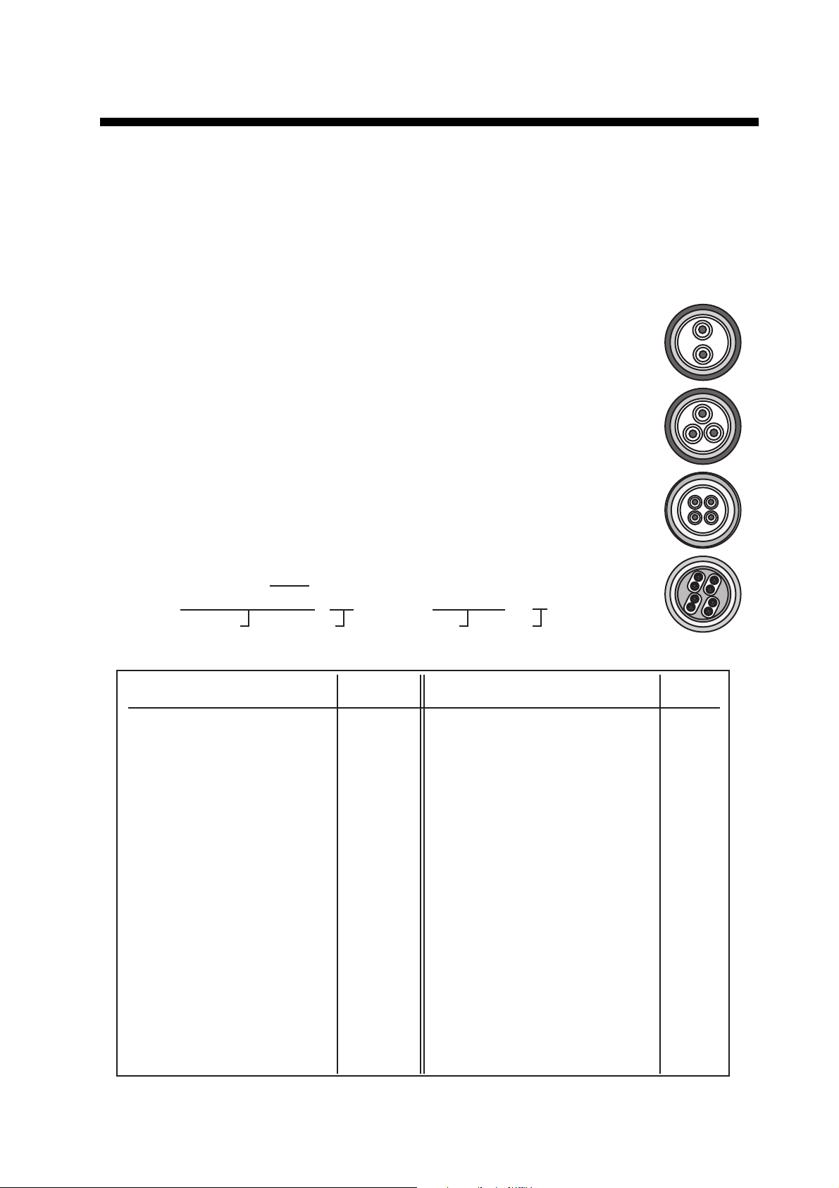
APPX. 1 JIS CABLE GUIDE
Core
Type Area Diameter
The following reference table lists gives the measurements of JIS cables commonly used with Furuno products:
TTYCSLA-4
MPYC-4
TPYCY
DPYCY
Cable
Diameter
DPYC-1.5 1.5mm
2
1.56mm 11.7mm
DPYC-2.5 2.5mm
2
2.01mm 12.8mm
DPYC-4 4.0mm
2
2.55mm 13.9mm
DPYC-6 6.0mm
2
3.12mm 15.2mm
DPYC-10 10.0mm
2
4.05mm 17.1mm
DPYCY-1.5 1.5mm
2
1.56mm 13.7mm
DPYCY-2.5 2.5mm
2
2.01mm 14.8mm
DPYCY-4 4.0mm
2
2.55mm 15.9mm
MPYC-2 1.0mm
2
1.29mm 10.0mm
MPYC-4 1.0mm
2
1.29mm 11.2mm
MPYC-7 1.0mm
2
1.29mm 13.2mm
MPYC-12 1.0mm
2
1.29mm 16.8mm
TPYC-1.5 1.5mm
2
1.56mm 12.5mm
TPYC-2.5 2.5mm
2
2.01mm 13.5mm
TPYC-4 4.0mm
2
2.55mm 14.7mm
TPYCY-1.5 1.5mm
2
1.56mm 14.5mm
TPYCY-2.5 2.5mm
2
2.01mm 15.5mm
TPYCY-4 4.0mm
2
2.55mm 16.9mm
TTYCSLA-1 0.75mm
2
1.11mm 9.4mm
TTYCSLA-1T 0.75mm
2
1.11mm 10.1mm
TTYCSLA-1Q 0.75mm
2
1.11mm 10.8mm
TTYCSLA-4 0.75mm
2
1.11mm 15.7mm
TTYCY-1 0.75mm
2
1.11mm 11.0mm
TTYCY-1T 0.75mm
2
1.11mm 11.7mm
TTYCY-1Q 0.75mm
2
1.11mm 12.6mm
TTYCY-4 0.75mm
2
1.11mm 17.7mm
TTYCY-4SLA 0.75mm
2
1.11mm 19.5mm
TTYCYSLA-1 0.75mm
2
1.11mm 11.2mm
TTYCYSLA-4 0.75mm
2
1.11mm 17.9mm
TTPYCSLA-1 0.75mm
2
1.11mm 9.2mm
TTPYCSLA-1T 0.75mm
2
1.11mm 9.8mm
TTPYCSLA-1Q 0.75mm
2
1.11mm 10.5mm
TTPYCSLA-4 0.75mm
2
1.11mm 15.3mm
EX: TTYCYSLA - 4 MPYC - 4
Designation type
# of twisted pairs
Designation type
# of cores
1 3 4 5 6 1 2 3 4
Cables listed in the manual are usually shown as Japanese Industrial Standard (JIS). Use the following guide to locate
an equivalent cable locally.
JIS cable names may have up to 6 alphabetical characters, followed by a dash and a numerical value (example:
DPYC-2.5).
For core types D and T, the numerical designation indicates the cross-sectional Area (mm
2
) of the core wire(s) in the
cable.
For core types M and TT, the numerical designation indicates the number of core wires in the cable.
1. Core Type
D:
Double core power line
T:
Triple core power line
M:
Multi core
TT:
Twisted pair communications
(1Q=quad cable)
2. Insulation Type
P:
Ethylene Propylene Rubber
3. Sheath Type
Y:
PVC (Vinyl)
4. Armor Type
C:
Steel
5. Sheath Type
Y:
Anticorrosive vinyl
sheath
6. Shielding Type
SLA:
All cores in one shield, plastic
tape w/aluminum tape
-SLA:
I
ndividually shielded cores,
plastic tape w/aluminum tape
Core
Type Area Diameter
Cable
Diameter
AP-1
Page 42
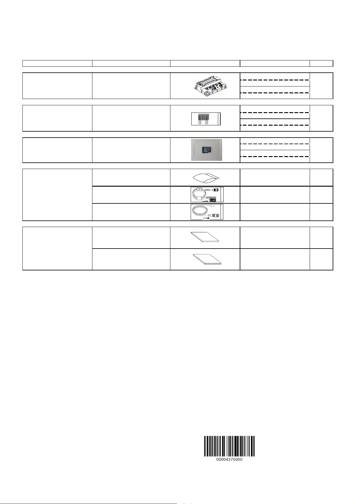
TZTBBX-E/-J
A-1
PACKING LIST
19BP-X-9854-0 1/1
N A M E O U T L I N E DESCRIPTION/CODE № Q'TY
ユニット UNIT
指示部
Multi Function Display UNIT
予備品 SPARE PARTS
予備品
SPARE PARTS
付属品 ACCESSORIES
工事材料 INSTALLATION MATERIALS
工事材料
INSTALLATION MATERIALS
図書 DOCUMENT
図書
DOCUMENT
PRODUCT NAME
SDカード(チャート)
MICRO SD CARD
ネジ袋詰め品
PACKAGED SCREW
電源ケーブル
POWER CABLE
ネットワークケーブル
NETWORK CABLE
装備要領書(和/英)
INSTALLATION MANUAL(JP/EN)
操作要領書(和/英)
OPERATOR'S GUIDE(JP/EN)
TZT10X/13X/16X/22X/24X/BBX
ヒューズ(5A)
FUSE (5A)
TZTBBX
310 x 210
TZTBBX-*
00166572000 **
FRU-60V-FU-5A
00019491310
JE07012-C170
99999980410
JE07012-B369
00020142810
FRU-3P-FF-A002M-003R
00020132110
FRU-RZWPNWP-005G
00020033910
IM*-45290-*
0002013741* **
OS*-45240-*
0002001451* **
1
1
1
1
1
1
1
1
*1 コード番号末尾の[**]は、選択品の代表コードを表します。
CODE NUMBER ENDING WITH "**" INDICATES THE CODE NUMBER OF REPRESENTATIVE MATERIAL.
(略図の寸法は、参考値です。 DIMENSIONS IN DRAWING FOR REFERENCE ONLY.)
JE07012-Y680
Page 43
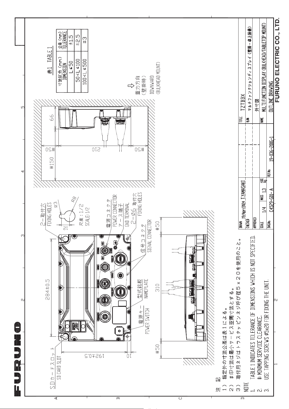
20/May/2024 A. Murao
$SSURYHG
D-1
20/May/2024 A. Murao
Page 44
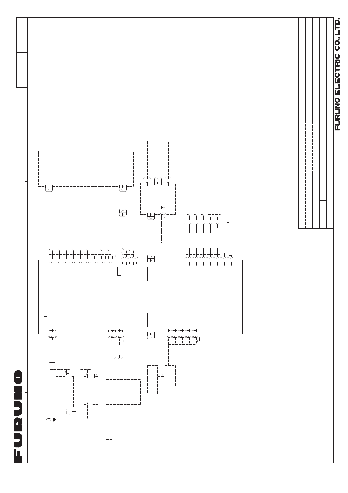
┦⤖⥺ᅗ
S-1
࣐ࣝࢳࣇࣥࢡࢩࣙࣥࢹࢫࣉࣞ
7=7%%;
ྡ⛠
7,7/(
$,6ཷಙᶵ
$,65(&(,9(5
ࢿࢵࢺ࣮࣡ࢡ㨶᥈
1(7:25.6281'(5
'))%%'6(7&
)$
5$'$56(1625
࣮ࣞࢲ࣮ࢭࣥࢧ࣮
,3࣓࢝ࣛ
,3&$0(5$
02'=Pȭ
02'=Pȭ
02'=Pȭ
5-
5-
+8%
(7+(51(7+8%
5-
)585=:3:35=:31:3
5--1(7:25.
5-
P
9+30996[&
P
9'&
/$1[
ࢼࣟࢢ࣓࢝ࣛ
5(':+7
%/.:+7
%51:+7
㺏㺔㺚㺹
㺖㺹㺚㺹
㺟㺊㺚㺹
*1'
*1'
.32
5&$
ࢻ࢘ࢪࢡ &2$;
xx/Apr/2024 A. Murao
6+,(/'
6LJQDO
$1$/2*&$0(5$
*1'
%8==(5
(9(176:,7&+
$8723,/27
6059
:+7
ࢩࣟ࢜ࣁ࢝ࢲࢡࣟࢳࣕ
)58&&&$)5*P
-
7'%
08/7,
32:(56:,7&+
%/8
*5<
5('
25*
%/.
33/
㺯㺵㺙㺕
*1'
%8==
7'$
3:5B6:
9B287
(9(17B6:
%51
.3,
7<$0$6$.,
$SU
'5$:1
20/May/2024 A. Murao
&+(&.('
ീฟຊᶵჾ࣍ࢫࢺ3&
+'0,6285&(+2673&
)58+''$3*P
-
+'0,,1
70'6B'$7$B3
70'6B'$7$B1
70'6B'$7$B6+,(/'
70'6B'$7$B3
70'6B'$7$B6+,(/'
70'6B'$7$B1
70'6B'$7$B3
70'6B'$7$B6+,(/'
70'6B'$7$B1
7'06B&/2&.B3
70'6B&/2&.B6+,(/'
70'6B&/2&.B1
1&
1&
''&B'$7$
''&B&/2&.
86%&$%/(
)580$()0%-*P
-86%
*1'
9B287
+27B3/8*B'(7(&7
8B'B1
8B9%$6
8B,'
8B'B3
࣮ࢧࢿࢵࢺࣁࣈ
*1'
1$0(
0$66
20/May/2024 A. Murao
6&$/(
$33529('
08/7,)81&7,21',63/$<
NJ
,17(5&211(&7,21',$*5$0
5()1R
&&$
':*1R
32:(5
*1'
08/7,)81&7,21',63/$<
ࢹࢫࣉࣞ
࣐ࣝࢳࣇࣥࢡࢩࣙࣥ
㺏㺓 %/8
$&'&㟁※㺳㺤㺍㺢
&21
73<&
9$&
&21
$&'&32:(5
6833/<81,7
+&*1'
ȭ+]
7=7%%;
35
ࡲࡓࡣ25
ᩚὶჾ
5(&7,),(5
'3<&
9$&
ȭ+]
-
5('
㺏㺔
$
)583))$05P
9'&
$
,9VT
35
10($
1(7B6
6+,(/'
-
5('㺏㺔
)5810($300))
)5810($3))
ࢪࣕࣥࢡࢩࣙࣥ
࣎ࢵࢡࢫ
0&8+
1(7B&
1(7B+
:+7
㺖㺹 %/.㺚㺹㺏㺓
P
),
-81&7,21%2;
*3%
1(7B/
%/8
1$9SLORW
6$7(//,7(&203$66
9'&
%
- +'0,287
)58+''$3*
P
ࢱࢵࢳࣔࢽࢱ࣮
728&+021,725
86%&$%/(
86%
-
9%$6
)5883&$38%
86%ࣁࣈ
P
'B1
86%+8%
'B3
*1'
665;B3
665;B1
*1'
667;B1
667;B3
6+,3<$5'6833/<
㐀⯪ᡤᡭ㓄ࠋ
࢜ࣉࢩࣙࣥࠋ
127(
ὀグ
㸨㸯㸧
&
'
237,21
㸨㸰㸧
Page 45

Page 46

Page 47

Page 48
9-52 Ashihara-cho,
A
JUN
2024
.
Pub. No.
(
)
Nishinomiya, 662-8580, JAPAN
・FURUNO Authorized Distributor/Dealer
All rights reserved.
TEHI
TZTBBX
Printed in Japan
IME-45290-A
0 0 0 2 0 1 3 7 4 1 1
 Loading...