

Page 1
Icon (home/displays), power switch operations
Operational Overview
How to select a display
MULTI FUNCTION DISPLAY
TZT22X/24X
Operator’s Guide
Model
This guide provides the basic operating procedures for this equipment. For detailed information, see the Operator’s
Manual, available on our homepage. Connection of sensors required.
iPhone, iPod and iPad are trademarks of Apple Inc. Android is a trademark of Google Inc. All brand and product
names are trademarks, registered trademarks or service marks of their respective holders.
The layout of the screen illustrations in this guide may differ depending on your system configuration and settings.
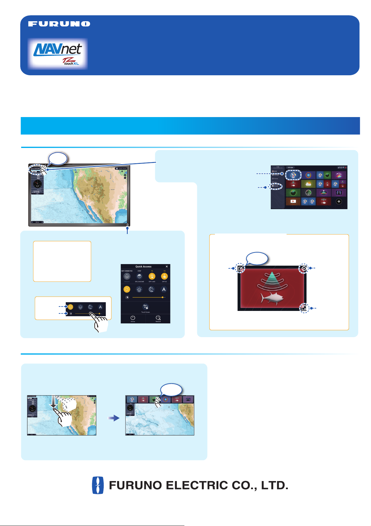
Displays the
home page.
Long tap a display icon to edit, delete, resize, or
change its location.
Display icon long tapped
Edit
Delete
Size
location
Tap
www.furuno.com
Swipe downward from
top of display.
- Tap a display icon on the home page (see illustration above).
- Tap a display icon on the Quick page.
- Tap a display icon on the home page (see illustration above).
- Tap a display icon on the Quick page.
- Turns on power.
- Shows [Quick Access] window.
Device: Powers off
this unit.
Network: Powers off all
NavNet TZtouch series
units in network.
Day
Hue:
Brilliance:
Display icons
(max. 16 on home page)
“eGuide” provides
an abbreviated
operator’s guide.
(large or small)
Tap
Tap
㼟
.
Page 2
Touchscreen operations
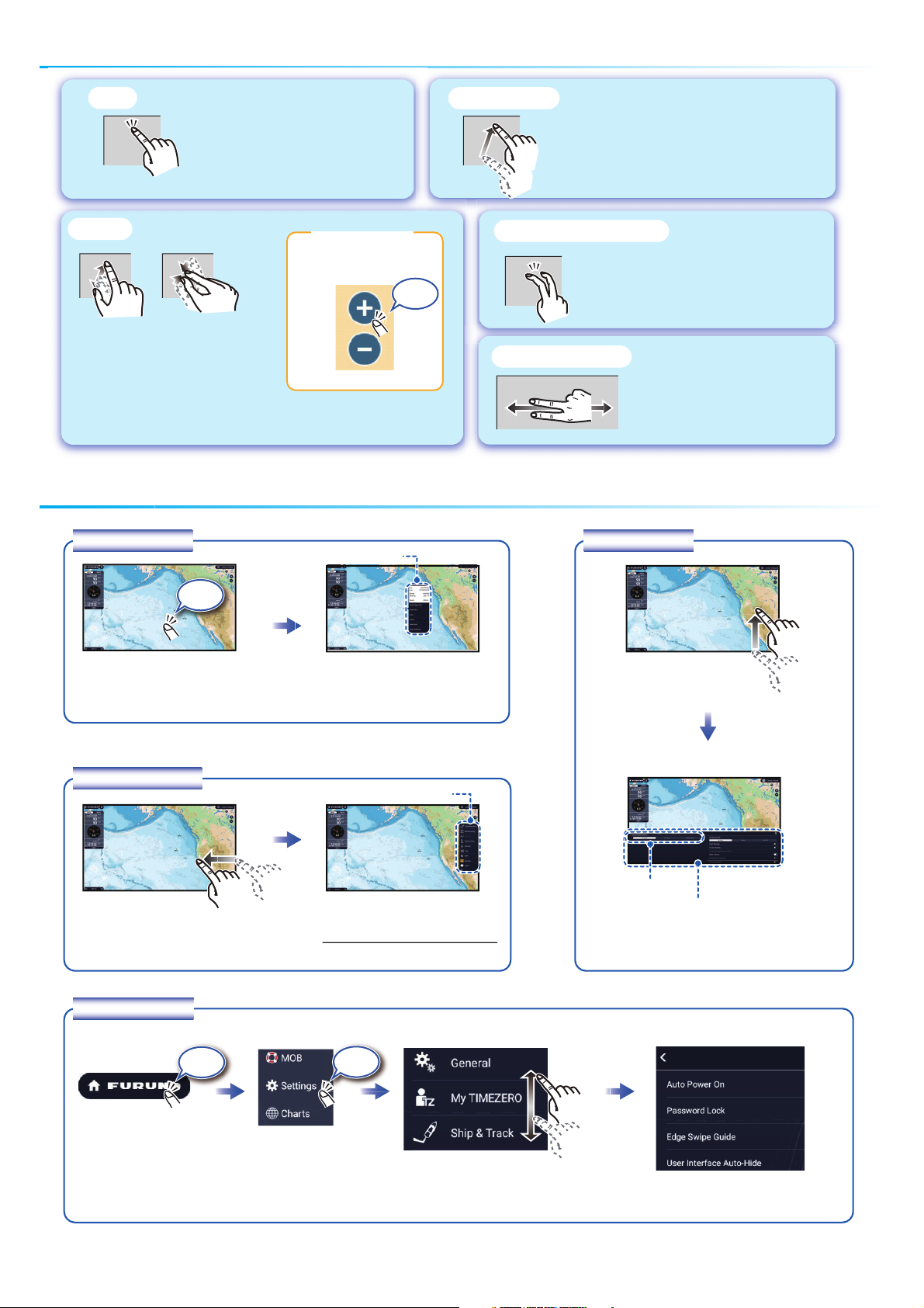
Ta p
- Select an item on a menu.
- Tap the display or an object to
show the corresponding pop-up
menu.
Pinch
Zoom in Zoom out
- Zoom in, zoom out the chart
plotter and weather displays.
- Change the range on the radar
and fish finder displays.
Menu operation
Pop-up menu
Range buttons
Zoom
Zoom
in
in
Zoom
Zoom
out
out
Pop-up menuPop-up menu
Tap
Drag, swipe
- Move the chart.
- Scroll the menu.
- Show Slide-out menu, Layers menu.
Two finger (long) tap
Do the function assigned to [Two
Finger (Long) Tap Function] in the
[Settings] - [General] menu.
Two finger drag
Change the viewpoint
position on the 3D display.
Layers menu
Ta p
Tap screen (applicable
point, object, etc.).
(”>” indicates additional options.)
Slide-out menu
Swipe leftward from the right edge.
Settings menu
Tap the required function.
Slide-out menuSlide-out menu
Tap the required function.
Icon color and function state
Yellow: ON, White: OFF
Swipe upward from
the bottom edge.
Layers menuLayers menu
Ta b
Tap the required function.
(To switch between menus,
swipe or tap applicable tab.)
Ta p
Tap the [FURUNO] icon.
Tap [Settings].
Ta p
Drag to find required
menu, then tap item.
2
Tap the required menu item.
Page 3
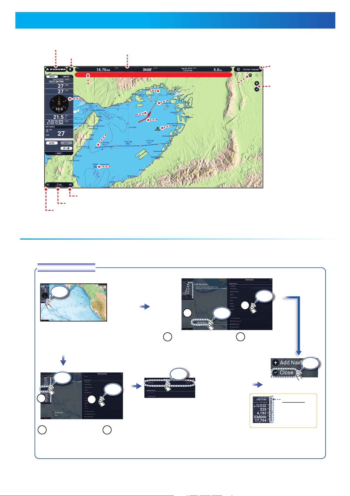
Chart Plotter
Tap the data box to
remove or change.
Remove a data box: Tap [Remove].
Change data: Tap data to display.
Swipe from the left edge of the screen rightward to show navigation data in the data area at the left edge of the screen.
To hide the data area, swipe the data area leftward or tap the [NavData] indication (yellow) in the Slide-out menu.
Data box settings
Tap [Edit] to show
[Edit NavData] display.
To remove a data box, or
change the displayed data:
Tap [Change Type]
to change the data
display method,
among Graphic
(analog), Numeric
(digital) and Graph.
Grip icon
Drag the grip
icon to move
the data box.
Ta p
Ta p
Ta p
Ta p
Ta p
Ta p
Ta p
Event icon
Range
buttons
Display orientation switch (NU/HU)
2D/3D switch
Scale bar
*: Arrival or departure position,
selectable on Layers menu.
Center
Vessel
[FURUNO] icon
Data
area
Speed Alarm
COG vector
(dashed line)
Inactive route
(expanded)
Navigation bar
Inactive route
(sleeping)*
Undo,
Redo
buttons
Page 4
Points/boundaries
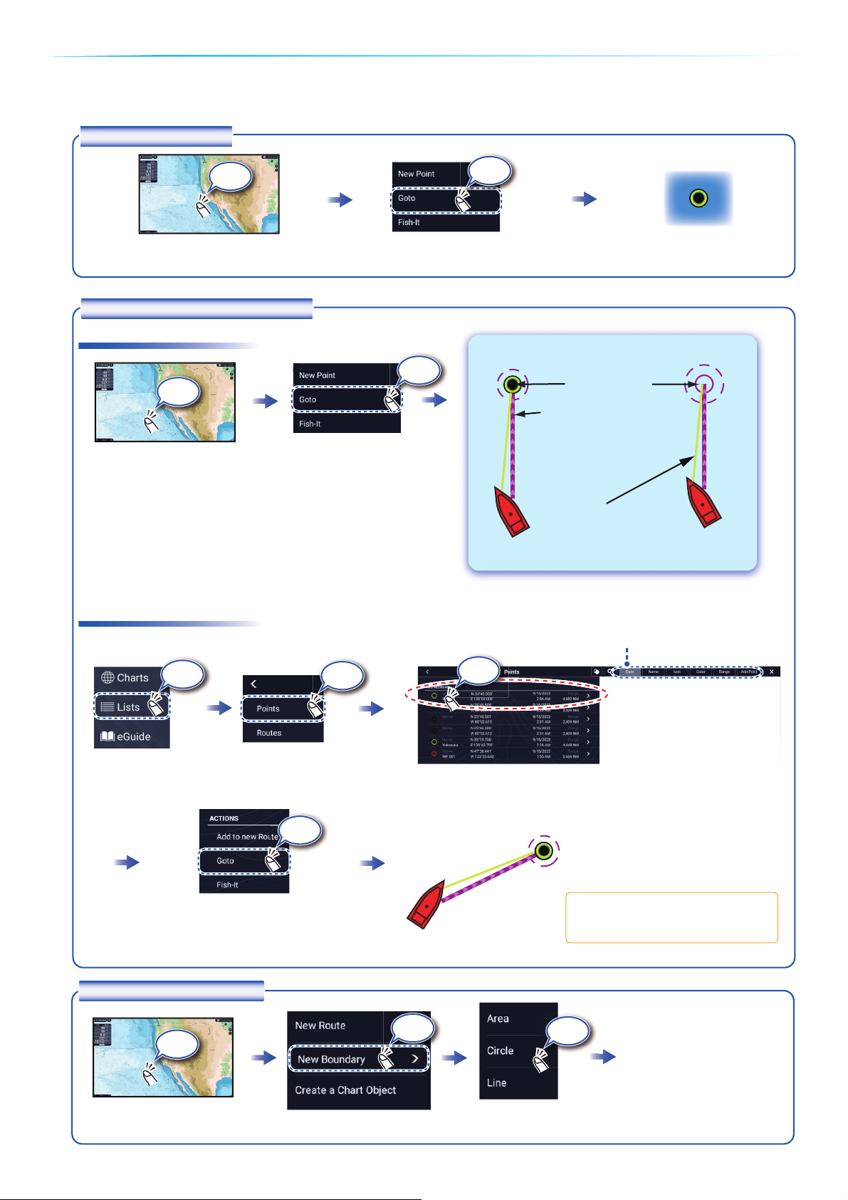
Points can be entered on the chart plotter display (radar, fish finder and weather displays also) to mark important
locations such as a good fishing spot. Point attributes (position, symbol type, color, etc.) are recorded to the Points
list. Also, boundaries can be set at the position desired (net position, area to avoid, etc.).
Tap where to enter a point.
The point is entered
on the screen.
Tap a point or the location
to set as destination.
On-screen point Selected location
How to enter a point
Yellow line:
Shortest course from own
ship to the destination.
Purple line (with arrow):
Indicates course to go to
the destination.
How to set a point as destination
Tap [Lists] on the
home page.
Destination point
Lists
If a point was tapped.
Note: [Find on Chart] puts the
selected point at the screen center.
Sort the list by date, name, icon, color, range.
How to set a boundary
Tap the position where to
set a boundary.
Tap the shape to use for
the boundary.
[Area]/[Line]: Tap necessary points to complete
the boundary, referring to
"Route" on the next page.
[Circle]: Drag icons to
adjust the size and
position, and then tap
[End Boundary].
Ta p
Ta p
Ta p
Ta p
Ta p
Ta p
㻙
Ta p
Ta p
Ta p
Ta p
Ta p
Page 5
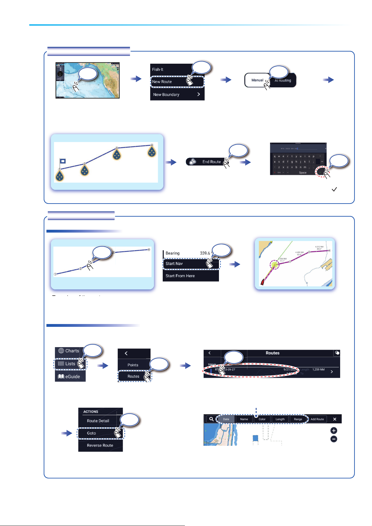
Routes
A route is comprised of a series of waypoints leading to a destination. Routes are saved to the routes list.
Tap the first point for the route.
At the last point
Select [Manual] or [AI Routing]*.
How to create a new route
How to follow a route
Tap a leg of the route.
Home page
Tap the route to use.
Enter a name for the route, then tap [ ].
(Top right corner)
Lists
1st point
(route start point)
Last
point
Ta p
Ta p
Ta p
Ta p
Ta p
Ta p
Ta p
Sort list by date, name, color, length, or range.
Ta p
Ta p
Ta p
Ta p
*: For AI Routing, tap only 2 points (1st and last).
The optimum route is automatically created.
Page 6
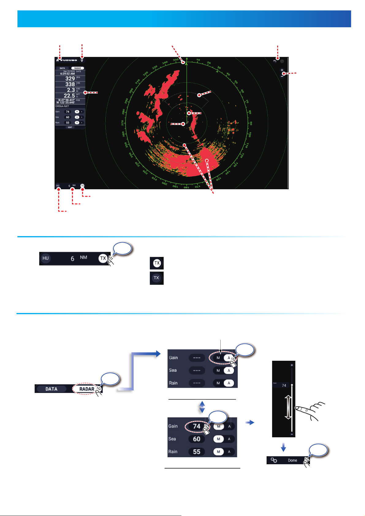
Radar
Switch
[FURUNO] icon
Event icon
Data
area
Own ship icon
TX/STBY switch
Radar range
Orientation mode switch
North mark
Redo, Undo buttons
Range
buttons
Guard
zone
Heading
line
Fixed range rings
How to switch between standby and TX
Ta p
: TX
(bottom left corner of the screen)
TX
: Standby
How to adjust the gain / sea clutter / rain clutter
“A” means automatic adjustment.
“M” means manual adjustment.
Switch
Ta p
(At top of data area)
Auto adjustment mode
Switch
Ta p
Tap to switch between
automatic and manual.
Drag or tap
the slider bar
to adjust.
Ta p
Manual adjustment mode
6
Ta p
(Top right corner)
Page 7
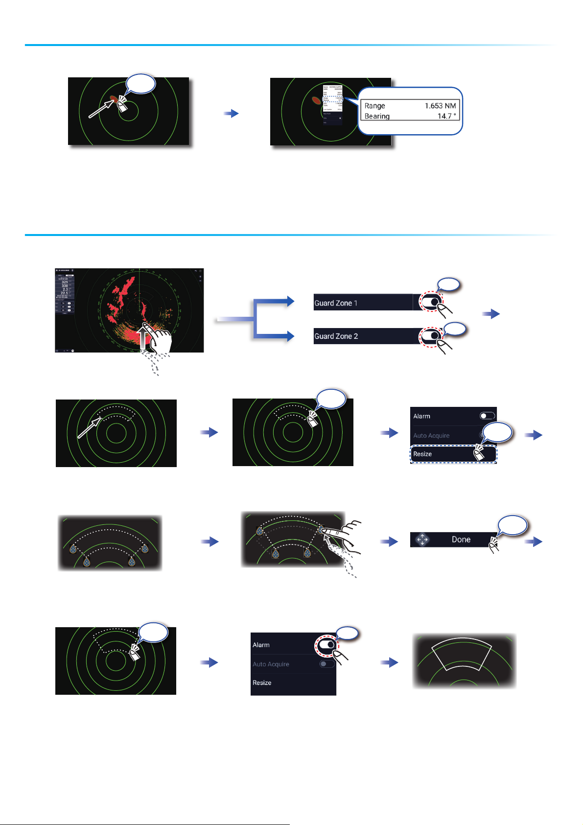
Tap a target to show its range
and bearing from own ship.
How to measure the range, bearing from own ship to a target
A guard zone alerts you (with aural and visual alarms) when a radar target enters the area you
specify.
The guard zone appears in dashed
lines.
An icon appears at each corner
of the guard zone.
The dashed lines change to
solid lines, indicating the
guard zone is active.
Drag the icons to set guard zone.
Tap dashed line on guard zone.
Tap the guard zone again.
(Top right corner)
Ta p
Ta p
Ta p
20
30
40
60
Open the Layers
menu, tap the
[Overlays] tab.
ON
ON
Ta p
Ta p
ON
Page 8
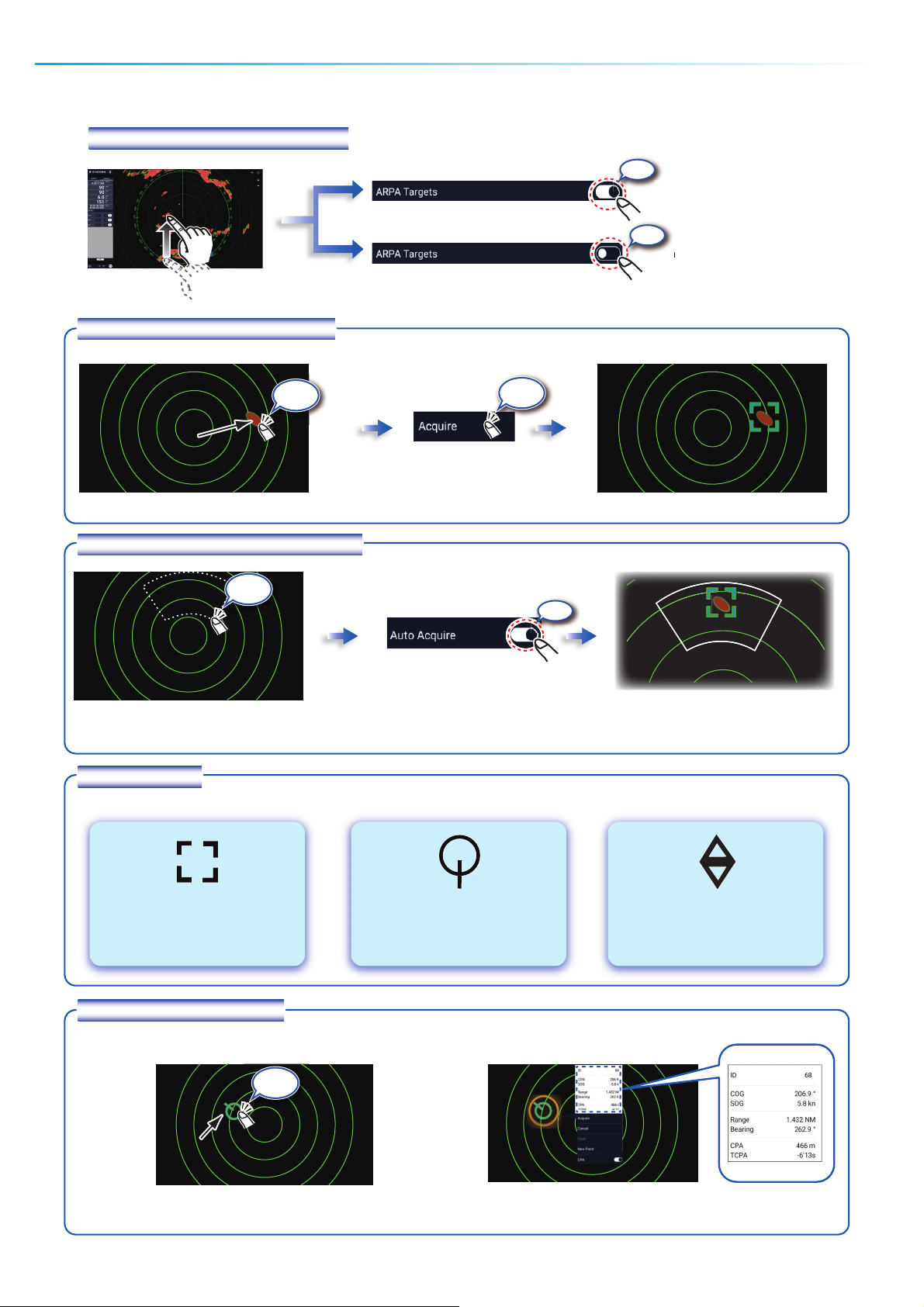
ARPA
Operation
ARPA is an anti-collision aid that tracks the movement of other ships to help prevent collision. ARPA not only tracks other ships
but also provides their navigation data. Targets can be acquired manually, automatically, or both automatically and manually.
How to show, hide ARPA symbols
How to manually acquire a target
Tap the target to acquire.
ARPA symbols
How to automatically acquire a target
At acquisition
Lost target
How to display target data
1
30 seconds
after acquisition
1
Set a guard zone, then tap the
guard zone.
Tap an ARPA target to show its data.
4
ON
1
The dashed lines change to solid lines,
indicating the guard zone is active.
4
Ta p
Ta p
Ta p
Ta p
Open the Layers menu,
tap the [Overlays] tab.
20
30
40
60
80
ARPA symbols ON
ARPA symbols OFF
ON
OFF
Page 9
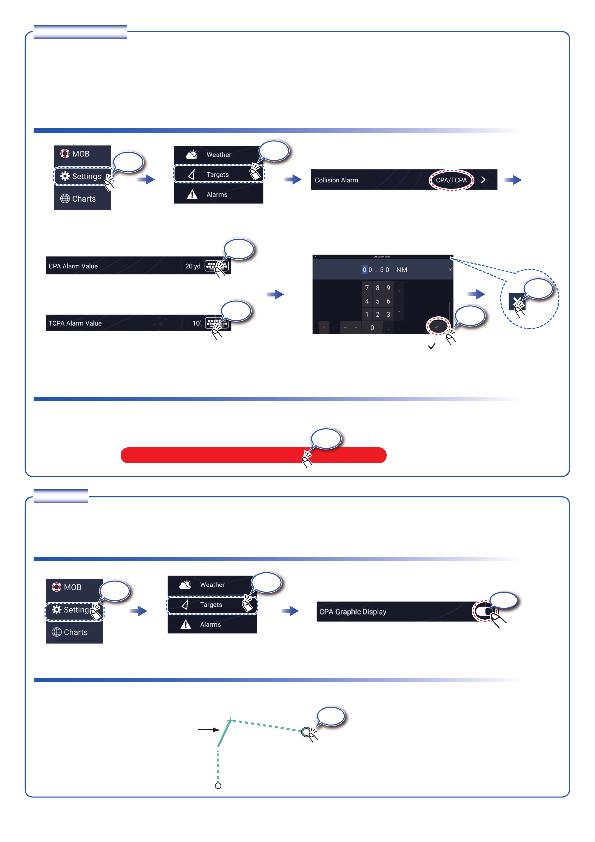
CPA/TCPA alarm
CPA/TCPA Alarm
he alarm
The CPA/TCPA alarm releases an aural alarm and a visual alarm (message in Status bar) when both the CPA
and TCPA of a tracked target are equal to or lower than the CPA/TCPA alarm setting.
CPA: Closest point of approach
TCPA: Time to closest point of approach
How to set the CPA/TCPA alarm
Ta p
Ta p
Home page
Select CPA/TCPA for Collision Alarm; tap “>”.
Ta p
OR
Ta p
Set the alarm value, then tap [ ].
How to acknowledge the CPA/TCPA alarm
Tap the alarm message (top of screen) to acknowledge the alarm and stop the aural alarm.
Ta p
Ta p
Ta p
CPA Line
The CPA Line feature gives you a visual line that depicts the closest point of approach to a selected ARPA target. To
use this feature, own ship position and heading data are required.
How to enable the CPA Line feature
Ta p
Home page
Ta p
㻻㻺
How to show the CPA Line
Tap an ARPA target (condition: target's CPA/TCPA must be a positive value) on the radar or chart plotter.
Ta p
CPA Line
ARPA target
Own ship
5
9
Page 10
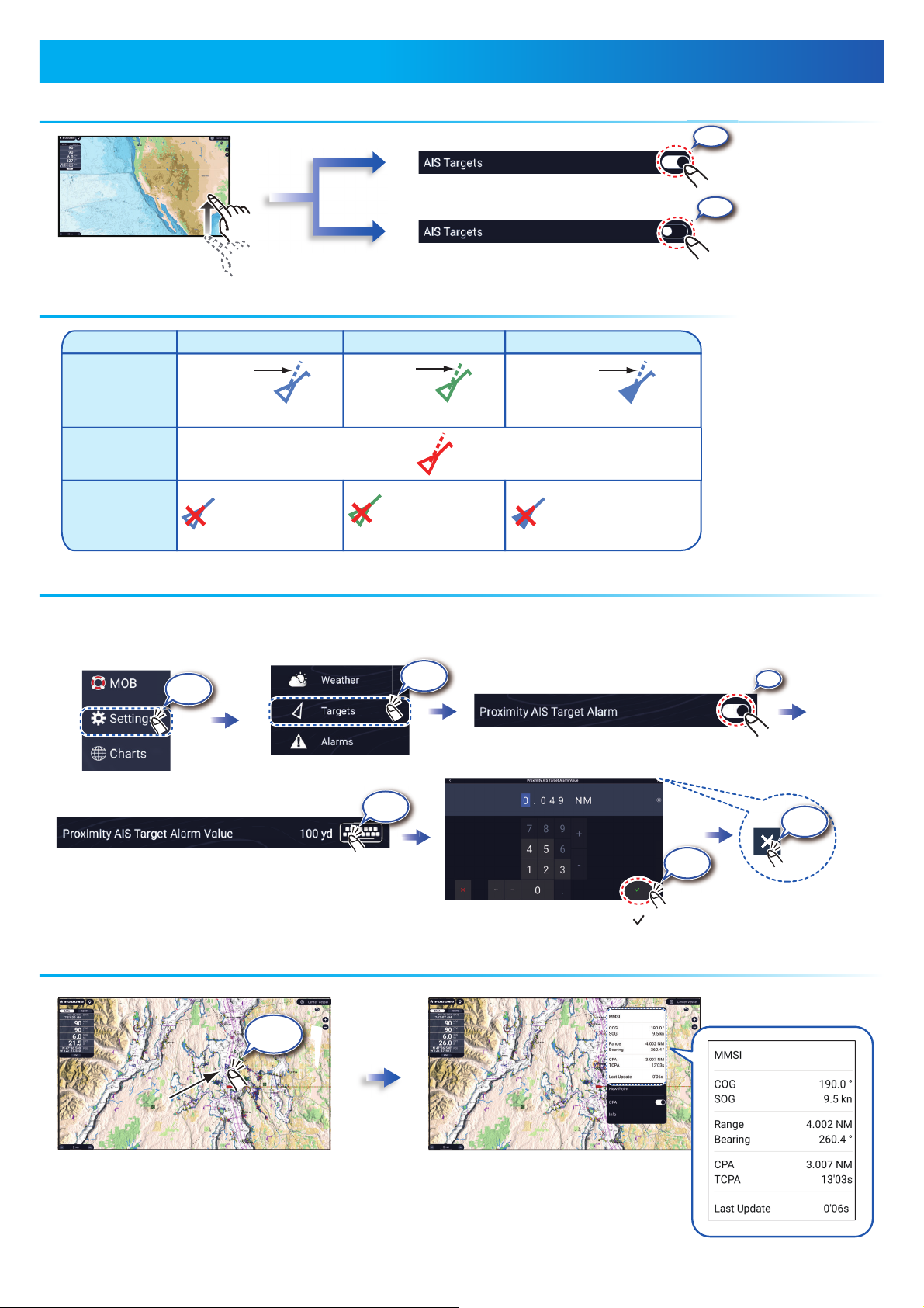
AIS symbols ON
AIS symbols OFF
AIS
target symbols
The proximity AIS target alarm releases aural and visual alarms when the distance between own ship and an AIS target is near
the alarm value.
AIS
(Automatic Identification System)
Set the alarm value, then tap [ ].
ON
Color: Blue
SOG and
COG vector
Color: Red
Color
- AIS target: Blue
- Cross: Red
Color
- AIS target: Green
- Cross: Red
Class A AIS
Activated
target
Dangerous
target
Lost
target
BFT* AIS
Class B AIS
Color: Green
SOG and
COG vector
SOG and
COG vector
Color: Blue (filled)
Color
- AIS target: Blue (filled)
- Cross: Red
*: Blue Force Tracking
Home page
Ta p
20
Open the Layers menu,
tap the [Overlays] tab.
Tap AIS symbol.
Ta p
Ta p
ON
Ta p
Ta p
OFF
Ta p
987654321
987654321
Page 11
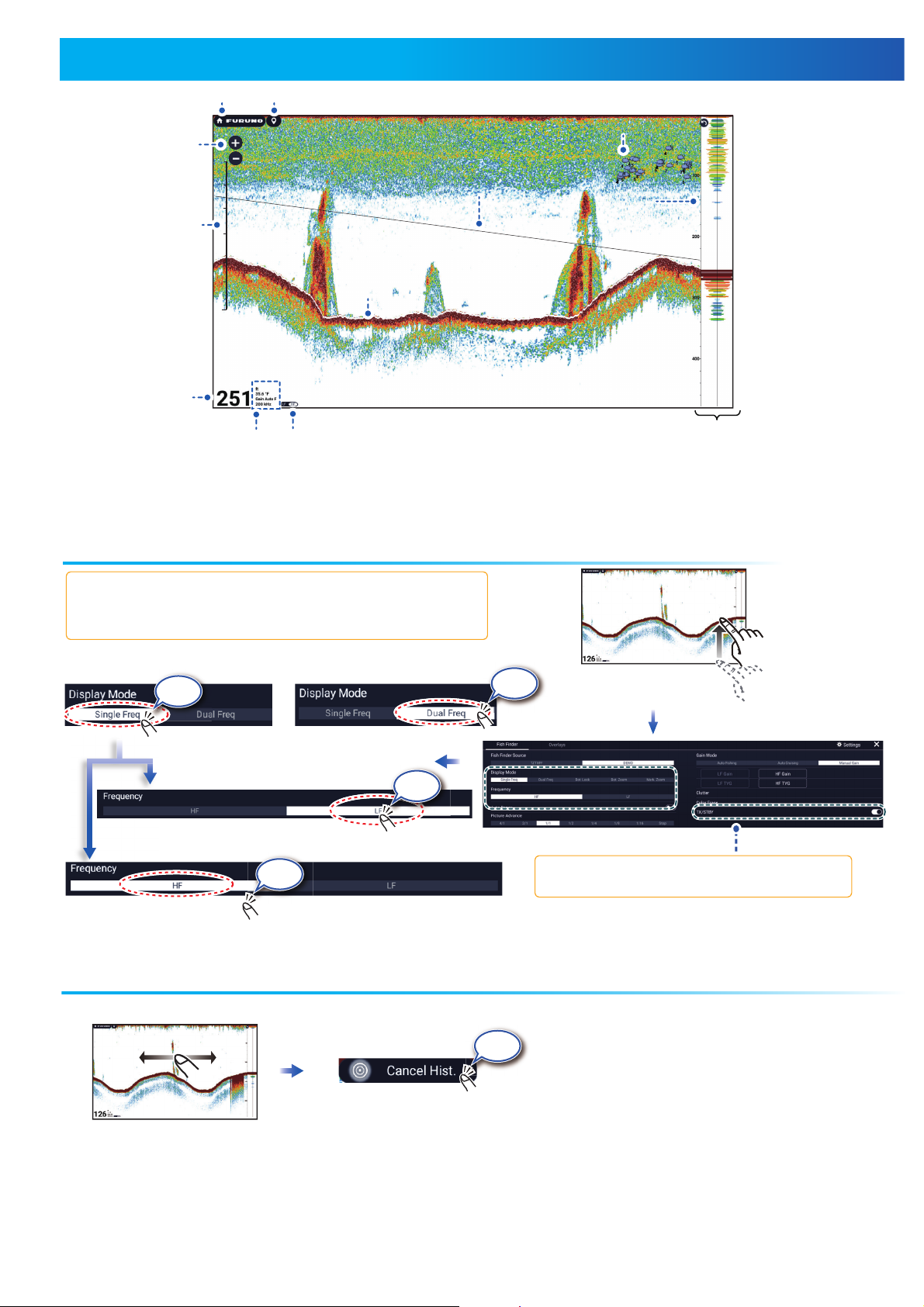
[TX/STBY] toggles between TX and standby.
Fish Finder
How to show past echoes (echo history)
Swipe leftward or rightward
to show past echoes.
Return to normal display.
*1 Requires ACCU-FISHTM compatible transducer on the network.
*
2
Required water temperature sensor on the network.
From top:
Unit, Temp.
Gain, Freq.
Home icon
Event icon
Depth
A-scope
Fish symbol *
1
Depth
scale
Water temp
graph*
2
(HF: High Freq.)
Single Freq.
Dual Freq.
Low frequency: For “normal” use.
High (Middle) frequency: For detailed observation of schools of fish.
Dual frequency: Show both the low and high frequency pictures.
Ta p
Ta p
Ta p
Open the Layers menu;
tap the [Fish Finder] tab.
(Top right corner)
Ta p
(LF: Low Freq.)
Ta p
30
34
38
40
Water
temp.
scale
*2
Range
buttons
Page 12
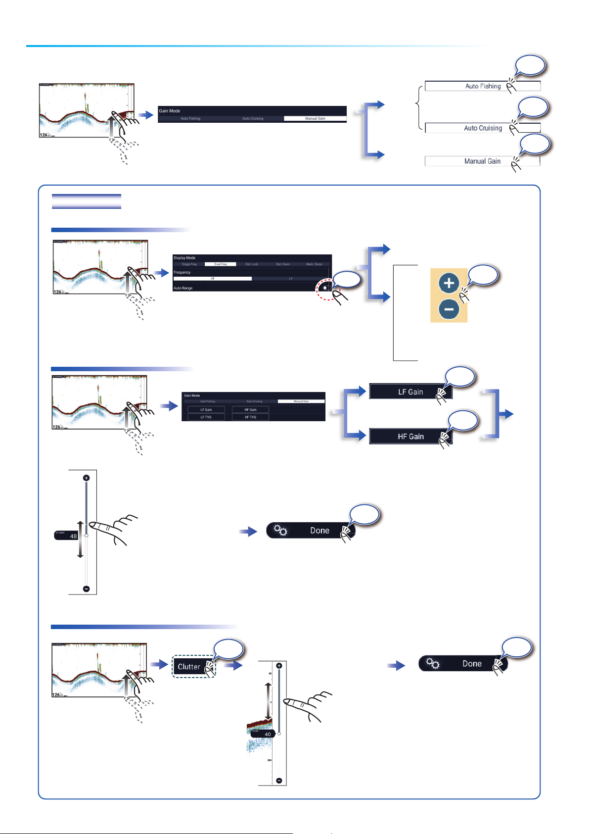
(Top right corner)
Manual mode
The fish finder is available in automatic and manual operation. For automatic operation, gain, clutter and
TVG are automatically adjusted.
Pinch screen.
Auto
mode
Manual
mode
OR
(Tap [+], [-] icon at left edge
of screen.)
Drag the slider bar
to set the gain.
(Gain can also be adjusted by
tapping the slider bar.)
For dual frequency transducer
Open the Layers
menu, tap the
[Fish Finder] tab.
Open the Layers
menu, tap the
[Fish Finder] tab.
Open the Layers
menu, tap the
[Fish Finder] tab.
Increase
range
Decrease
range
Ta p
OFF
Ta p
Ta p
Ta p
The larger the value, the more the clutter is reduced.
Open the Layers
menu, tap the
[Fish Finder] tab.
T
Ta p
Ta p
Ta p
Ta p
Drag the slider bar
to set the range.
(Range can also be adjusted
by tapping the slider bar.)
(Top right corner)
Ta p
Page 13
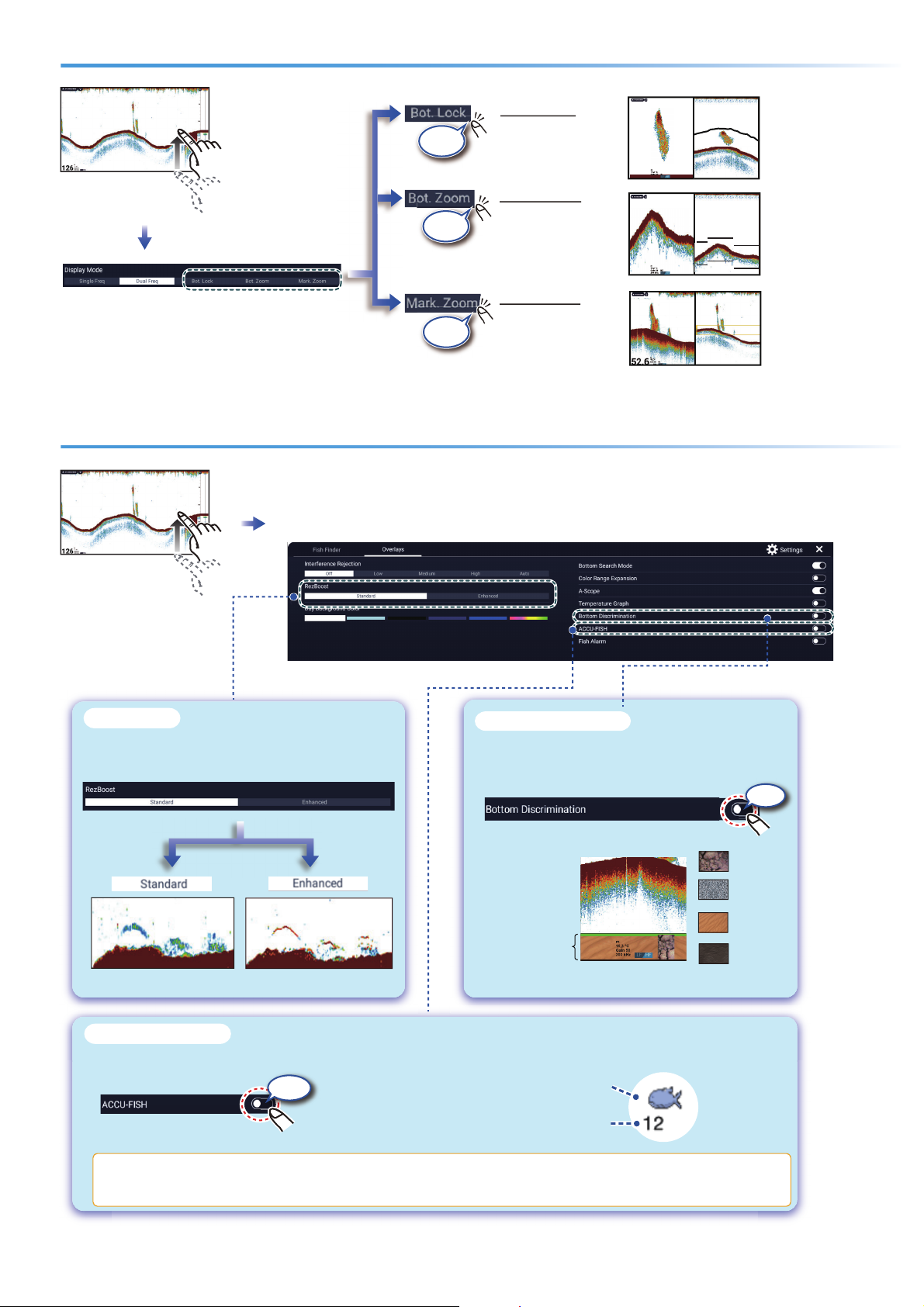
ACCU-FISHTM/Bottom Discrimination/RezBoost
TM
Zoom display
Bottom Zoom
Find bottom contour
and hardness.
Open the Layers
menu, tap the [Fish
Finder] tab.
Bottom Lock
Search for
bottom fish.
20.5
200 kHz
20.5
Marker Zoom
Help determine the
size of a school of
fish in the middle
layer.
- Short tail indicates
soft bottom.
- Long tail indicates
hard bottom.
Show the Layers
menu, tap the
[Overlays] tab.
Raise the echo resolution. (Requires RezBoost
TM
capable transducer on the network.)
RezBoost
TM
(Standard mode)
(High resolution mode)
Fish size or depth
Fish symbol
You can select fish symbol type, and fish size or depth indication from the menu - go to home page, [Settings], [Fish
Finder].
ACCU-FISH
TM
Detected fish can be marked with a fish symbol.
(Requires ACCU-FISHTM capable transducer on the network.)
Bottom
discrimination
display
The most probable bottom material.
Rock
Gravel
Sand
Mud
Show probable bottom hardness.
(Requires bottom discrimination capable transducer
on the network.)
Bottom Discrimination
200
Ta p
Ta p
Ta p
ON
ON
576
Page 14
53
53
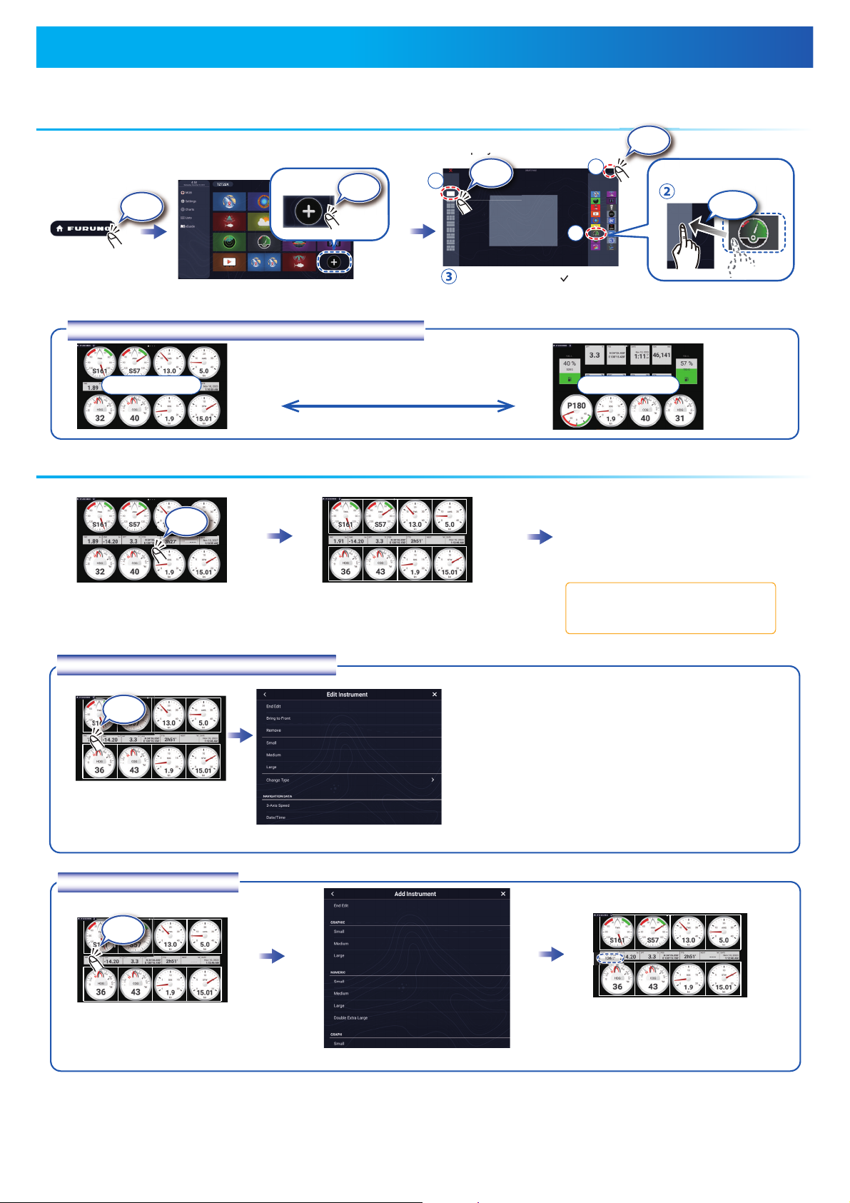
How to enable the instrument display
Add the instrument display icon to the home page to show the instrument display.
How to edit the instrument display
Tap the instrument display,
then tap [Edit Page] on the
pop-up menu.
A white line surrounds each
indication.
In the edit mode, you can remove,
change, add, rearrange indications.
Tap the screen, then tap [End Edit] on
the pop-up menu.
With connection of appropriate sensors, the instrument display shows various navigation data.
Instrument Display
Swipe rightward or leftward
to switch between displays.
How to switch instrument displays (ex. full display)
Sailing displaySailing display
Cruising displayCruising display
After setting, tap [ ].
(Incorporation in multiscreen is also possible.)
In the edit mode, tap the
indication to remove or change.
How to remove or change an indication
- Remove indication: Tap [Remove].
- Change size: Tap [Small], [Medium], [Large],
[Double Extra Large]*.
- Change type: Tap [Change Type], then tap
desired size.
- Change indication: Tap indication in [NAVIGATION DATA], [ROUTE INFORMATION], [WIND
AND WEATHER], and [ENGINE].
*: Numeric displays only
Ta p
TZT19F
In the edit mode, tap a location
not occupied by an instrument display.
How to add an indication
Tap a size in desired category.
Tap added instrument display to
change displayed data (see
above).
Ta p
p
y
Ta p
Ta p
1
2
3
Drag
53
53
53
Rudder
Ta p
Ta p
Ta p
Page 15
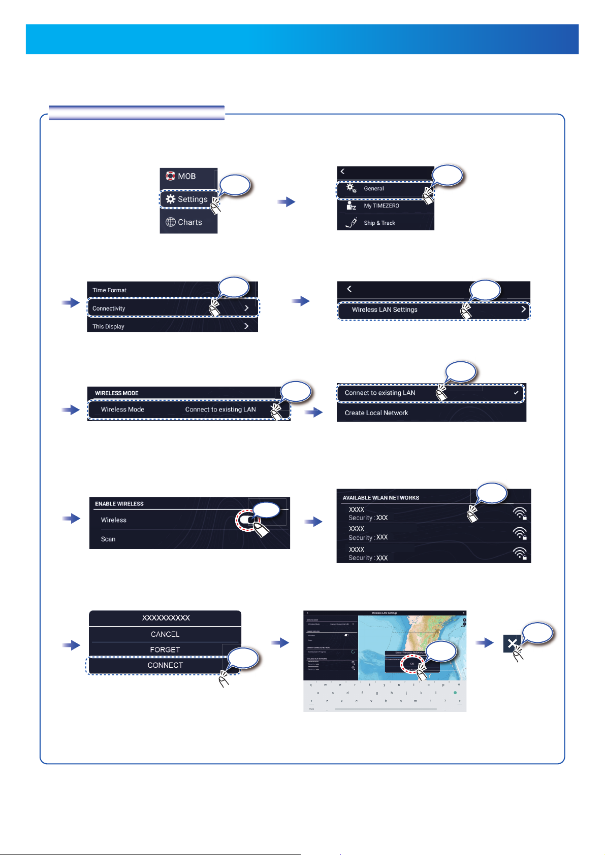
Wireless LAN Settings
You can connect to the internet with the wireless LAN signal to download weather information, update the software, and
connect to an iPhone, iPod, iPad, or Android
TM
device, to operate and monitor a NavNet TZtouch XL device.
How to connect to an existing LAN
Connect to the existing LAN to download weather data or update the software. For smartphone and tablet settings, refer
to appropriate manuals.
Ta p
Home page
Ta p
Ta p
Ta p
Select [Wireless Mode].
Ta p
Ta p
Ta p
Select [Connect to existing LAN].
Ta p
ON
Tap network required.
Ta p
Ta p
Enter the password, then tap [OK].
15
Page 16
TZT22X
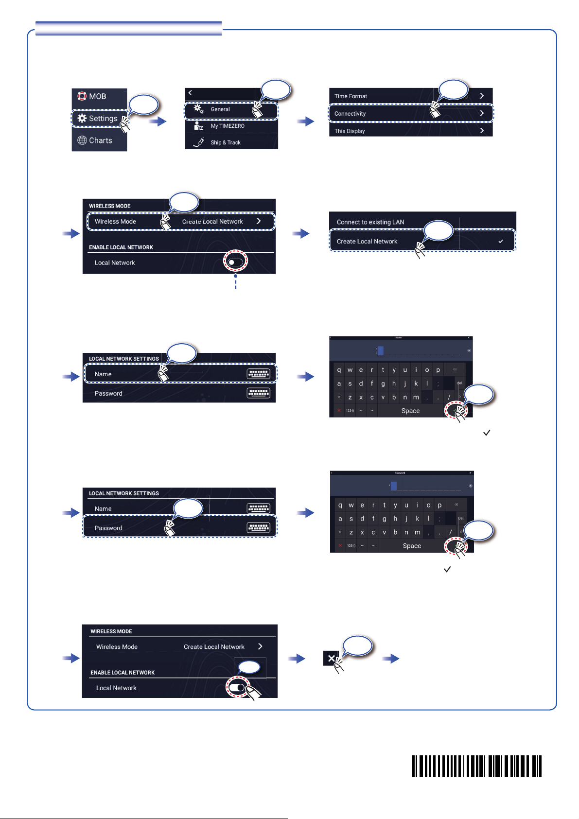
How to create a local wireless network
Create a local wireless network to enable operation, monitoring of the TZTtouch XL from a smartphone or tablet.
Check that [OFF] is selected.
Select [Create Local Network].
Enter the name of the network, then tap [ ].
Enter the password, then tap [ ].
ON
Connect to the NavNet TZtouch
XL from the smartphone or tablet.
Ta p
Ta p
Ta p
Ta p
Ta p
Ta p
Ta p
TZT22X
Home screen
Ta p
Ta p
Ta p
XXXXXXXX
XXXXXXXX
T Z T 2 2 X
X X X X X
00020014511
Pub. No. OSE-45240-B
(2401, CHYA) TZT22X/TZT24X
 Loading...